EP3969817B1 - Gargerät mit ausserhalb des garraums angeordneten sensoreinheiten - Google Patents
Gargerät mit ausserhalb des garraums angeordneten sensoreinheiten Download PDFInfo
- Publication number
- EP3969817B1 EP3969817B1 EP20726338.5A EP20726338A EP3969817B1 EP 3969817 B1 EP3969817 B1 EP 3969817B1 EP 20726338 A EP20726338 A EP 20726338A EP 3969817 B1 EP3969817 B1 EP 3969817B1
- Authority
- EP
- European Patent Office
- Prior art keywords
- cooking
- cooking appliance
- sensor units
- cooking chamber
- opening
- Prior art date
- Legal status (The legal status is an assumption and is not a legal conclusion. Google has not performed a legal analysis and makes no representation as to the accuracy of the status listed.)
- Active
Links
Images


Classifications
-
- H—ELECTRICITY
- H05—ELECTRIC TECHNIQUES NOT OTHERWISE PROVIDED FOR
- H05B—ELECTRIC HEATING; ELECTRIC LIGHT SOURCES NOT OTHERWISE PROVIDED FOR; CIRCUIT ARRANGEMENTS FOR ELECTRIC LIGHT SOURCES, IN GENERAL
- H05B6/00—Heating by electric, magnetic or electromagnetic fields
- H05B6/64—Heating using microwaves
- H05B6/6447—Method of operation or details of the microwave heating apparatus related to the use of detectors or sensors
- H05B6/645—Method of operation or details of the microwave heating apparatus related to the use of detectors or sensors using temperature sensors
- H05B6/6455—Method of operation or details of the microwave heating apparatus related to the use of detectors or sensors using temperature sensors the sensors being infrared detectors
-
- F—MECHANICAL ENGINEERING; LIGHTING; HEATING; WEAPONS; BLASTING
- F24—HEATING; RANGES; VENTILATING
- F24C—DOMESTIC STOVES OR RANGES ; DETAILS OF DOMESTIC STOVES OR RANGES, OF GENERAL APPLICATION
- F24C7/00—Stoves or ranges heated by electric energy
- F24C7/08—Arrangement or mounting of control or safety devices
- F24C7/082—Arrangement or mounting of control or safety devices on ranges, e.g. control panels, illumination
- F24C7/085—Arrangement or mounting of control or safety devices on ranges, e.g. control panels, illumination on baking ovens
-
- A—HUMAN NECESSITIES
- A47—FURNITURE; DOMESTIC ARTICLES OR APPLIANCES; COFFEE MILLS; SPICE MILLS; SUCTION CLEANERS IN GENERAL
- A47J—KITCHEN EQUIPMENT; COFFEE MILLS; SPICE MILLS; APPARATUS FOR MAKING BEVERAGES
- A47J37/00—Baking; Roasting; Grilling; Frying
- A47J37/06—Roasters; Grills; Sandwich grills
- A47J37/0623—Small-size cooking ovens, i.e. defining an at least partially closed cooking cavity
-
- A—HUMAN NECESSITIES
- A47—FURNITURE; DOMESTIC ARTICLES OR APPLIANCES; COFFEE MILLS; SPICE MILLS; SUCTION CLEANERS IN GENERAL
- A47J—KITCHEN EQUIPMENT; COFFEE MILLS; SPICE MILLS; APPARATUS FOR MAKING BEVERAGES
- A47J37/00—Baking; Roasting; Grilling; Frying
- A47J37/06—Roasters; Grills; Sandwich grills
- A47J37/0623—Small-size cooking ovens, i.e. defining an at least partially closed cooking cavity
- A47J37/0664—Accessories
-
- F—MECHANICAL ENGINEERING; LIGHTING; HEATING; WEAPONS; BLASTING
- F24—HEATING; RANGES; VENTILATING
- F24C—DOMESTIC STOVES OR RANGES ; DETAILS OF DOMESTIC STOVES OR RANGES, OF GENERAL APPLICATION
- F24C7/00—Stoves or ranges heated by electric energy
-
- F—MECHANICAL ENGINEERING; LIGHTING; HEATING; WEAPONS; BLASTING
- F24—HEATING; RANGES; VENTILATING
- F24C—DOMESTIC STOVES OR RANGES ; DETAILS OF DOMESTIC STOVES OR RANGES, OF GENERAL APPLICATION
- F24C7/00—Stoves or ranges heated by electric energy
- F24C7/08—Arrangement or mounting of control or safety devices
- F24C7/082—Arrangement or mounting of control or safety devices on ranges, e.g. control panels, illumination
-
- H—ELECTRICITY
- H05—ELECTRIC TECHNIQUES NOT OTHERWISE PROVIDED FOR
- H05B—ELECTRIC HEATING; ELECTRIC LIGHT SOURCES NOT OTHERWISE PROVIDED FOR; CIRCUIT ARRANGEMENTS FOR ELECTRIC LIGHT SOURCES, IN GENERAL
- H05B6/00—Heating by electric, magnetic or electromagnetic fields
- H05B6/64—Heating using microwaves
- H05B6/6408—Supports or covers specially adapted for use in microwave heating apparatus
- H05B6/6411—Supports or covers specially adapted for use in microwave heating apparatus the supports being rotated
-
- H—ELECTRICITY
- H05—ELECTRIC TECHNIQUES NOT OTHERWISE PROVIDED FOR
- H05B—ELECTRIC HEATING; ELECTRIC LIGHT SOURCES NOT OTHERWISE PROVIDED FOR; CIRCUIT ARRANGEMENTS FOR ELECTRIC LIGHT SOURCES, IN GENERAL
- H05B6/00—Heating by electric, magnetic or electromagnetic fields
- H05B6/64—Heating using microwaves
- H05B6/6447—Method of operation or details of the microwave heating apparatus related to the use of detectors or sensors
- H05B6/6458—Method of operation or details of the microwave heating apparatus related to the use of detectors or sensors using humidity or vapor sensors
-
- H—ELECTRICITY
- H05—ELECTRIC TECHNIQUES NOT OTHERWISE PROVIDED FOR
- H05B—ELECTRIC HEATING; ELECTRIC LIGHT SOURCES NOT OTHERWISE PROVIDED FOR; CIRCUIT ARRANGEMENTS FOR ELECTRIC LIGHT SOURCES, IN GENERAL
- H05B6/00—Heating by electric, magnetic or electromagnetic fields
- H05B6/64—Heating using microwaves
- H05B6/66—Circuits
- H05B6/68—Circuits for monitoring or control
- H05B6/687—Circuits for monitoring or control for cooking
Definitions
- the invention relates to a cooking appliance having a cooking space delimited by a cooking space wall, at least two sensor units arranged outside the cooking space and an opening in the cooking space wall, through which at least one property of the cooking space can be detected by means of one of the at least two sensor units.
- the invention can be applied particularly advantageously to household cooking appliances, in particular ovens and/or microwave ovens.
- WO 2015/141207 A1 discloses a cooking apparatus including an infrared sensor which is provided outside a cooking cavity and which uses a plurality of infrared sensor elements to detect the temperature of an object to be heated; and a direction setting motor that can change the direction of the infrared sensor.
- the cooking apparatus is configured such that the direction of the infrared sensor moves to a temperature detection position when temperature detection is performed, and the direction of the infrared sensor moves to a standby position when temperature detection is not performed.
- the direction of the infrared sensor moves to a temperature detection position when temperature detection is performed, and the direction of the infrared sensor moves to a standby position when temperature detection is not performed.
- EP 0 924 964 A2 discloses a microwave oven with an infrared sensor for sensing the temperature of food during cooking.
- the infrared sensor is directed diagonally downwards and backwards from the upper front edge of the cooking chamber.
- a shutter or shield protects the sensor when not needed to sense food temperature.
- This cooking appliance has the advantage that the wall opening can be used by different sensor units at different times. A particularly advantageous sensor position can thus be used for all of these sensor units.
- a further advantage in the event that at least two of the sensor units are imaging sensor units (e.g. an optical camera and an IR camera) is that the images from these sensors can be superimposed without further adjustment, since both the cooking chamber or the food to be cooked show from the same perspective. Only the sensor unit that is currently required is located at the wall opening, so that the sensor units that are not being used are protected from contamination (e.g. vapors, splashes of fat, etc.) and/or thermal radiation from the cooking chamber through the wall opening.
- Yet another advantage is that by providing only one wall opening for multiple sensor units, heat loss from a hot cooking space can be kept particularly low.
- the cooking appliance is advantageously a domestic cooking appliance.
- the cooking appliance is in particular an oven, a microwave oven or a combination thereof, for example an oven with a microwave function.
- the cooking appliance can also have a steam treatment function.
- the cooking chamber has a loading opening at the front has, which can be closed by a door.
- the appliance-internal cooking chamber wall (without a door) can also be referred to as a muffle.
- the sensor unit can have one or more individual sensor elements.
- the sensor unit is in particular a separately manufactured unit that is attached to the changing device.
- the wall opening is in particular a free or permeable opening, i.e. an opening that is not permanently covered by a pane (e.g. a transparent pane of glass) or the like.
- a pane e.g. a transparent pane of glass
- the wall opening can be permanently covered by a protective pane if this is metrologically permeable for all sensor units, ie allows a measurement of the associated at least one property of the cooking chamber for all sensor units.
- the sensor units include, for example, an optical camera and an IR camera, there can be a permanent protective pane in the form of a pane that is transparent, in particular transparent, for the optical and the relevant IR spectrum (e.g. NIR spectrum).
- the at least one property of the cooking space can be, for example, a physical variable such as a brightness and/or color distribution on the surface of the food to be cooked (e.g. to determine the degree of browning of the food), a temperature of the cooking space, a temperature distribution on one or more surfaces of the food to be cooked, humidity in the cooking space etc. and/or a chemical variable such as a proportion of one or more chemical substances in a cooking chamber atmosphere, e.g. a proportion of oxygen, etc.
- a property of the cooking space can thus include, for example, a property of the cooking space atmosphere and/or a property of the food to be cooked located in the cooking space.
- the changing device present outside of the cooking chamber is housed in particular within the cooking appliance, for example in an intermediate space between the cooking chamber wall and an outer housing of the cooking appliance. It is an advanced training that the changing device is arranged above the cooking chamber, because there is a lot of space to accommodate it.
- the changing device can be moved by motor, in particular by means of at least one drive motor such as an electric motor, in particular a stepper motor.
- each of the sensor units is assigned a specific position (also referred to below as "active position"), in which this sensor unit can detect at least one associated property of the cooking space through the wall opening.
- active position also referred to below as "active position”
- only one of the sensor units can be located in front of the wall opening in each time period.
- the other sensor units are arranged at a distance from the wall opening (which is also referred to below as the “standby position”) and cannot use it.
- the sensor units present thereon can be moved alternately individually in front of the wall opening in the cooking chamber wall.
- the motor is connected to a control device of the cooking appliance in order to bring the respective sensor unit in front of the wall opening automatically if necessary - e.g. program-controlled and/or depending on the situation, e.g. event-controlled.
- the changing device has a plurality of supports that can be moved by a motor, on each of which a sensor unit is arranged.
- This configuration has the advantage that it can be designed in a particularly diverse manner.
- the carriers can each assume two positions or positions permanently, namely the active position and the standby position. The carriers can be alternately brought into their active position. It is a development that the carrier can be folded between its active position and its standby position.
- the supports in particular foldable supports, are arranged in a ring around the wall opening.
- each of the carriers can be connected to an associated motor. Alternatively, all carriers can be moved by a single motor.
- the changing device has a motor-driven movable carrier on which the at least two sensor units are arranged.
- This carrier is therefore a common carrier for the at least two sensor units.
- this common carrier moves, all sensor units arranged on it are also moved.
- the optical sensor can be an optical camera, e.g. an imaging digital camera, in particular a color camera.
- the temperature sensor can be a temperature probe or an imaging thermal imaging (IR) camera.
- the substance sensor can be an oxygen sensor, e.g. a lambda sensor.
- the material sensor can be a spectrometer.
- the changing device is additionally equipped with at least one cover that can be moved or brought in front of the wall opening.
- the changing device can be adjusted in such a way that the cover can be brought in front of the wall opening instead of the sensor units.
- the cover can be arranged and moved analogously to a sensor unit.
- the changing device has a plurality of supports that can be moved by a motor
- the cover can be present on one of the supports instead of a sensor unit.
- the changing device is a motorized movable carrier has, on which the at least two sensor units are arranged, the cover can also be present on the carrier.
- the cover provided on the carrier can be a separately manufactured component or an integral part of the carrier.
- the changing device has, in addition or as an alternative to the above-described cover attached to a carrier, a further cover in the form of a protective pane that can be moved in front of the wall opening, with this protective pane (in contrast to a protective pane permanently attached in front of the wall opening) for at least one of the sensor units is metrologically permeable, ie allows a measurement of the associated at least one property of the cooking chamber, and is metrologically impermeable to at least one other of the sensor units.
- the movable protective pane can be a pane (e.g.
- the changing device can be set up or controlled in such a way that the protective screen covers the wall opening when a sensor unit is located in front of the wall opening, for which the protective screen is metrologically permeable, and releases the wall opening when a sensor unit is located in front of the wall opening, for which the protective pane is metrologically impermeable. It is therefore a further development that the protective pane only covers the wall opening when required or is only removed from the (then temporarily free) wall opening when required.
- the protective pane can also be moved by a motor.
- the cooking chamber wall in the region of the wall opening is shaped as a protuberance-in particular in the shape of a funnel or truncated cone--which widens in the direction of the cooking chamber.
- the protuberance can have been prefabricated as an independent component.
- the protective pane if present, can be moved in particular in front of the end face of the protuberance on the cooking chamber side.
- the wall opening can in particular correspond to the end face of the protuberance facing away from the cooking space.
- the travel position in which the wall opening is covered by the cover on the carrier is a "normal position” or “rest position” of the changing device and the other sensor units are only moved in front of the wall opening when required and then again the normal position is assumed.
- the sensor units are advantageously only brought up to the opening and are thus exposed to the hot and/or dirty cooking chamber (e.g. due to splashes of fat, liquid or vapors) when a measurement is required.
- the changing device is moved back into the rest position immediately after the measuring time of the sensor unit located in front of the opening has expired, and the sensor unit is thus brought back into a protected position. The exposure time for the sensor units is therefore short, as is the heat loss from the hot cooking chamber.
- the changing device is provided or equipped with at least one imaging digital camera and one imaging IR camera and, in particular, also has or provides a cover.
- the carrier can be rotated by a motor and its angular positions can be adjusted in such a way that by rotating the carrier one of the sensor units can be brought in front of the opening.
- This achieves the advantage that a particularly compact and robust arrangement can be provided.
- a cover on the carrier this can be arranged analogously to the sensor units.
- the carrier can be connected to a motor or to a drive shaft of the motor via a drive shaft, for example. By rotating the drive shaft, predetermined angular positions of the carrier can be adjusted about its axis of rotation.
- the carrier can be rotatable within a limited angular range, ie in an angular range of less than 360°, or alternatively can be circumferentially rotatable.
- the carrier can be connected to the motor or to a drive shaft of the motor via a drive shaft. By rotating the motor, specific predetermined angular positions of the carrier can be set about its axis of rotation. That by rotation of the carrier respectively one of the sensor units can be brought in front of the opening includes, in particular, that each of the sensor units is assigned a specific angular position in which this sensor unit can detect at least one associated property of the cooking chamber through the opening.
- the sensor units (and possibly the cover) are arranged in an arc around an axis of rotation of the carrier. In this way, it is advantageously achieved that they can be precisely positioned on the wall opening by simply rotating them.
- the arcuate arrangement can be a circular or annular sector-shaped arrangement.
- the sensor units (and possibly the cover) are aligned radially outwards in relation to the axis of rotation of the carrier.
- This configuration includes in particular that a measurement field or field of view of the sensor units is aligned radially with respect to the axis of rotation.
- an optical axis of a camera can be aligned radially outward with respect to the axis of rotation of the carrier.
- the axis of rotation of the carrier is aligned at least approximately parallel to a wall of the cooking chamber wall that has the wall opening. In other words, the axis of rotation of the carrier is aligned at least approximately perpendicular to a normal direction of the wall opening.
- the wall of the cooking chamber wall in which the wall opening is located can generally be a ceiling, a rear wall, a left side wall, a right side wall or a rear wall.
- the wall opening can also be located in a transition between such walls.
- the wall of the cooking chamber wall can also include the door closing the cooking chamber, since in the closed state this also represents an area or a side of the cooking chamber wall. It is therefore a development that the changing device, including the sensor units attached thereto, is accommodated in a door of the cooking appliance. This gives the advantage that a viewing angle from the closed door roughly corresponds to the viewing angle of a user when opening the door to look.
- the sensor units are aligned parallel to the axis of rotation of the carrier, for example in the manner of a turret.
- the axis of rotation of the carrier is then in particular offset at least approximately perpendicularly to a wall of the cooking chamber wall having the opening or offset at least approximately parallel to a normal direction of the wall opening.
- the carrier has a band-shaped carrier wall arranged around its axis of rotation in the shape of a sector of an arc, in particular in the shape of a ring sector, with at least two placement locations for sensor units being present on the carrier wall at an angular offset to one another.
- a particularly easy-to-manufacture and robust option is advantageously provided for attaching the sensor units to the carrier.
- a placement area can also be provided for this.
- a cover that is produced separately has the advantage that, compared to the material of the carrier (e.g. plastic), it can be produced in a particularly simple manner from a particularly heat-resistant material, e.g. from ceramic or mirrored metal.
- the cover can be integrated into the carrier, for which case no specially designed mounting location needs to be provided.
- the carrier can be motor-translatory, in particular linear, moveable or displaceable.
- this can then be designed, for example, as a flat band or plate and be movable, for example, parallel to the cooking chamber wall having the opening.
- the design as a flat plate can also be advantageous if the sensor units are aligned parallel to the axis of rotation of the rotatable carrier.
- the support wall can then be designed, for example, as a circular or sector-shaped plate.
- the sensor units can be easily attached to the carrier and can also be moved precisely in front of the opening in the cooking chamber wall without adjustment are.
- the fact that an outside of the support wall can be moved along in front of the opening in the cooking chamber wall includes, in particular, that the support wall (from the wearer's point of view) can rotate or move translationally along its longitudinal extent in front of the wall opening.
- the support wall remains in particular in front of the opening, but with a different section depending on the position. If the carrier is rotatable and the sensor units are aligned radially outwards with respect to the rotational axis of the carrier, the longitudinal extension of the carrier wall corresponds to its direction of movement, for example a circumferential direction of the rotational axis if rotatable.
- At least one of the placement locations has a window that can be brought into alignment with the wall opening in the cooking chamber wall. By bringing the window into overlap with the wall opening, the view into the cooking chamber can be made available for the respective sensor unit.
- the window can, for example, be an opening or a hole in the support wall.
- all placement locations provided for sensor units also referred to below as “sensor placement locations”) have such a window.
- the sensor units can be arranged on the support wall in basically any order.
- One configuration is that at least two placement locations or the associated sensor units are separated from one another by a cover, the cover being located in the direction of movement of the carrier, in particular the carrier wall, ie in particular between the at least two placement locations.
- the advantage is achieved that only a small amount of movement or movement is necessary in order to move placement locations or the sensor units present in them from the rest position in front of the wall opening.
- At least two placement locations or the associated sensor units are arranged next to one another on one end section of the support wall and the cover is arranged on the other end section.
- the sensor units are arranged in the cooking appliance so that they can be ventilated. As a result, they can advantageously be cooled during a cooking operation.
- the cooking appliance has at least one fan or ventilator, by means of which an appliance-internal (forced) flow of cooling air can be generated in the cooking appliance (typically between the cooking chamber wall and a housing of the cooking appliance).
- an appliance-internal (forced) flow of cooling air can be generated in the cooking appliance (typically between the cooking chamber wall and a housing of the cooking appliance).
- Such a flow of cooling air can be a flow of cooling air that is already being used or has been used to cool other areas, e.g. to cool electronics and/or to cool doors.
- such a cooling air flow can also be an independent, in particular also a separate cooling air flow, which leads from the outside to the changing device, in particular to its sensor units.
- Improved cooling of the sensor units generally results when cooling air is guided to the sensor units directly from the outside or from a cooler base area of the device.
- the sensor units can be arranged in the cooling air flow inside the device.
- the carrier is designed to be air-permeable for this purpose, for example by providing suitable openings, slots, etc.
- the carrier wall can be connected to the axis of rotation via a frame construction.
- an assembly station has a sleeve attached to the inside of a window in a support wall.
- a region of a sensor unit facing the cooking chamber can be inserted, in particular plugged, into this sleeve at the rear, or the sensor unit can be attached to the sleeve (but not introduced).
- a front open face of the sleeve may correspond to the window, while the rear or rear open face is provided as an attachment or insertion opening for the sensor unit. If the sensor unit is a camera, its lens, for example, can be attached to the back of the sleeve (eg placed on the sleeve) or inserted into the sleeve.
- the area of the sensor unit located on or in the sleeve is usually that area which is most exposed to the thermal radiation incident from the wall opening and also to contamination such as splashes of liquid or grease.
- the sleeve can therefore advantageously serve as a positioning aid and spacer for the associated sensor unit.
- the sleeve can be perforated laterally or on the casing side in order to allow the cooling air flow to cross the sleeve. If the sensor unit is inserted or attached in the sleeve, the air flow directed through the sleeve can cause cooling of the associated sensor unit.
- the sleeve thus advantageously makes it possible to easily position the associated sensor unit on the carrier and cool it in the active and standby positions.
- the sleeve is designed as an air flow collector or is connected to an air flow collector.
- the airflow plenum is located in the cooling airflow area of the cooking appliance and is shaped and oriented to selectively direct a portion of the cooling airflow into the sleeve.
- On the opposite side of the sleeve it can have an air outlet opening. Consequently, the air flow collector enables a particularly reliable flow of air across the sleeve.
- the air flow collector has a flow cross section that narrows in the direction of flow of the incoming air. This increases a flow speed of the cooling air in the sleeve, which enhances a cooling effect.
- the flow of cooling air can also be so strong that it now deflects grease and liquid splashes in front of the sensor unit.
- the air flow collector thus advantageously enables simple positioning of the associated sensor unit on the carrier, its cooling in the active and standby positions, and protection against contamination in the active position.
- the air flow collector can, for example, be funnel-shaped, with its wider opening directed against the direction of the cooling air flow and with its narrower opening opening laterally into the sleeve.
- the sleeve can have an air outlet opening.
- the cover covers the opening in the cooking chamber wall without a gap. So are all the sensor units in their standby position (which corresponds to a rest position of the wearer or the changing device) can by means of Cover the cooking chamber opening and the air duct are closed at the same time.
- the cover can protrude, for example, on the outside of a support wall, in particular with a height which corresponds or almost corresponds to the gap width.
- the changing device can also combine translatory movements and rotary movements and/or it can enable rotary movements of a sensor unit about a number of different rotary axes.
- a changing device can have a motor-rotatable base, for example circular disk-shaped, about a first--in particular vertical--rotational axis, on which a plurality of arms are rotatably or pivotably attached, with a sensor unit being attached to each of the arms.
- the axes of rotation of the cantilevers can each be aligned perpendicularly to the axis of rotation of the base, e.g. in the horizontal direction, and can be angularly offset or tilted with respect to one another, e.g.
- the object is also achieved by a method for operating a cooking appliance as described above.
- the method can be designed analogously to the cooking appliance and has the same advantages.
- One configuration is that during a cooking operation at least one of the sensor units is brought from a standby position into an active position by moving the changing device, a measurement is carried out by means of this sensor unit in the active position and this sensor unit after the measurement by moving the Changing device is immediately returned to the standby position.
- an exposure time of the sensor units to the cooking chamber is advantageously kept particularly short.
- one of the sensor units is an optical camera
- this can be used in a further development at the beginning of a cooking process in order to recognize, measure and/or display the food to be cooked in the cooking chamber.
- the optical camera is then only required at longer time intervals (eg from one to five minutes) for a short period of time to record an image in order to determine the cooking progress of the food. If the optical camera is only moved in front of the wall opening to take the picture and then brought back into the standby position immediately after the picture has been taken, the thermal load and the risk of contamination are high reduced.
- the optical camera can then advantageously be designed very inexpensively.
- An imaging IR camera may be moved to the active position at regular time intervals for a recording, especially in microwave mode (a fast mode that typically has a short cooking time) and then moved back to the standby position, in which it can be thermally cooled and protected from contamination.
- microwave mode a fast mode that typically has a short cooking time
- the cooking appliance can be an oven with microwave functionality, for example.
- the alternating or time-discrete use of different sensor units at a common location is utilized by means of the present cooking appliance.
- This is particularly advantageous for sensor units whose evaluation does not require a continuous or quasi-continuous data stream with as many measurements as possible per unit of time over a longer period of time.
- the evaluation of image information for measurement purposes e.g. an IR evaluation of temperature profiles or an optical recognition of food or light projection patterns
- the changing device does not conflict with the fact that at least one, in particular further, property of the cooking chamber can also be permanently detected by means of other sensors or sensor devices not arranged on the changing device.
- a temperature sensor for sensing a cooking chamber temperature can be arranged (for example in the cooking chamber) in such a way that it can measure the cooking chamber temperature continuously or quasi-continuously and the changing device has an optical camera and an IR camera.
- a humidity sensor and/or at least one chemical sensor can be provided permanently or on the changing device, depending on the technical specification.
- Fig.1 shows a sketch of a section of a cooking appliance 1 as a sectional side view, which has a cooking chamber 3 delimited by a cooking chamber wall 2 . Outside the cooking chamber 3 there is a motor-driven changing device 4 which is shown in its rest position.
- the changing device 4 has a change here an axis of rotation D motor-rotatable carrier 5, on which two sensor units are arranged, namely an optical camera 6 and an IR camera 7.
- the motor for rotating the carrier 5 is not shown, but can be a stepping motor, for example.
- the carrier 5 here has a band-shaped carrier wall 8 arranged around its axis of rotation D in the form of an arc sector, in particular in the form of a ring sector.
- An outer side 9 of the support wall 8 can be moved in front of a wall opening 10 in the cooking chamber wall 2, in particular it can be moved over it.
- the partial area of the cooking chamber wall 2 that has the wall opening 10 is a roof of the cooking chamber 2 here. They are directed through a respective window 13 in the support wall 8 and thus have a field of view that can be viewed through the respective window 13 .
- the cameras 6 and 7 are thus also arranged in an arc around the axis of rotation D of the carrier, and are also aligned radially outwards with respect to the axis of rotation D.
- a cover 14 which is arranged here along the support wall 8 or in the circumferential direction of the axis of rotation D between the optical camera 6 and the IR camera 7 or their placement locations 12 .
- the optical camera 6 and the IR camera 7 or their placement locations 12 are therefore separated from one another by the cover 14 in the direction of rotation.
- the optical camera 6, the IR camera 7 and the cover 14 are offset from one another in the circumferential or rotational direction, in particular equidistantly.
- the optical camera 6 , the IR camera 7 and the cover 14 can be brought alternately in front of the wall opening 10 by rotating the carrier 5 about the axis of rotation, for example by means of a control device (not shown).
- the axis of rotation D lies parallel to the cooking chamber wall 2. If, for example, an optical image or an IR image is to be recorded from the cooking chamber 3, the carrier 5 is rotated into an angular position in which the placement location 12 of the optical camera 6 or The window 13 associated with the IR camera 7 is aligned with the wall opening 10 .
- the cooking chamber 3 is visible to the optical camera 6 or the IR camera 7 through the respective window 13 and the wall opening 10 . In this “active position” the optical camera 6 or the IR camera 7 can take at least one picture from the cooking chamber 3 .
- the carrier 5 is rotated into its rest position, in which both cameras 6, 7 are in their “standby position”.
- the cover 14 now covers the wall opening 10, in particular tightly.
- the cover 14 can therefore be rotated in front of the wall opening 10 instead of the cameras 6 and 7 .
- the arrangement with the cover 14 between the two cameras 6 and 7 has the advantage that only a small rotation is required to bring the cameras 6 and 7 from their standby position in front of the wall opening 10 into their active position.
- Fig.2 shows in a too Fig.1
- Analogous representation shows a variant 1a of the cooking appliance 1 with a differently shaped development 2a of the cooking chamber wall 2.
- the cooking chamber wall 2, 2a in the region of the wall opening 10 has a protuberance 15 or recess directed out of the cooking chamber 3.
- the protuberance 15 is tubular, in particular in the shape of a truncated cone or funnel, and has the wall opening 10 on its inside end face.
- This variant has the general advantage that the cameras 6, 7 (and the sensor units in general) are positioned further away from the possibly hot cooking chamber wall 2 and are therefore installed in a cooler environment. This also enables easier cooling, since the greater distance from the remaining cooking chamber wall 2 or from the cooking chamber 3 results in a higher thermal resistance.
- the protuberance 15 can be produced by shaping (eg deep-drawing, embossing, etc.) the cooking chamber wall 2 .
- the protuberance 15 can be a component that is produced separately and then connected to the remaining wall 2 of the cooking space. This achieves the advantage that the protuberance 15 can be designed for a particularly effective reduction in heat conduction. For example, it can be made of poorly thermally conductive ceramics.
- the optional funnel or truncated cone shape of the protuberance 15 achieves the further advantage that the field of view of the cameras 6, 7 is not or not noticeably restricted.
- the protuberance 15 can be designed as a microwave barrier, since this prevents microwaves from passing through the wall opening 10 .
- the protuberance15 in the general case, a tube that is so narrow that waves cannot propagate through the tube.
- the funnel shape of the protuberance 15, which is optional here, increases its sealing effect, so that microwave tightness is achieved after a shorter distance.
- Fig.3 shows in a too Fig.1 analogous representation, a variant 1b of the cooking appliance 1 with a protuberance 15 and an additional protective disk 16.
- This cooking appliance 1, 1b is thus shown as a further development of the cooking appliance 1a, but the protective disk 16 can also be used in general, for example with the cooking appliance 1 without a protuberance 15.
- the protective pane 16 can be present as an alternative or in addition to the cover 14.
- the protective pane 16 consists here of inexpensive glass which is transparent to visible light but opaque to (N)IR radiation. For example, as shown, it can be moved by a motor parallel to the cooking chamber wall 2a and the wall opening 10 on the cooking chamber side.
- the protective pane 16 can represent part of the changing device 4 or can be controlled separately from it.
- the movement of the protective pane 16 can be controlled as follows, for example: when the carrier 5 is in the rest position, the protective pane 16 also covers the protuberance 15, namely its end face 17 on the cooking chamber side.
- the cover 14 and the protective pane 16 are then, for example, arranged at a distance of several millimeters to a few centimeters from one another and in particular aligned parallel to one another. This double protection against heat and dirt from the cooking chamber 3 is particularly advantageous during a pyrolysis operation.
- the protective pane 16 itself has a double effect: on the one hand it creates a barrier and thus prevents hot air from rising up to the sensor surface and prevents liquid and fat splashes from penetrating, on the other hand it can be made of poorly heat-conducting material (e.g Glass or glass ceramic poor heat conductivity compared to steel), which also increases the heat conduction of the cooking chamber wall 2a in the area of the protuberance 15. It is a further development of the protective pane 16 that, as indicated by dashed lines, it is designed to be significantly larger than the end face of the protuberance on the cooking chamber side, ie protrudes noticeably laterally beyond this end face. In this way, the thermal resistance of the cooking chamber wall 2a covered by it increases, so that less heat flows in the direction of the protuberance 15 and the cameras 6, 7.
- poorly heat-conducting material e.g Glass or glass ceramic poor heat conductivity compared to steel
- the protective screen 16 which is transparent for it, remains in front of the protuberance 15 and thereby protects the optical camera 6 from heat and dirt from the cooking chamber 3. If the IR camera 7 is in its active position, the protective screen is 16 moves away from the protuberance 15 and thus releases it.
- the protuberance 15 can be designed to be air-permeable, e.g. perforated or generally perforated, in order to further reduce the heat conduction thereby. This reduction in heat conduction can be particularly effective if the protuberance 15 is located in an area of a cooling air flow of the cooking appliance 1 .
- Fig.4 shows in a too Fig.1 analog representation, a cooking appliance 21 with a changing device 22 in the rest position.
- the cooking appliance 21 is designed similarly to the cooking appliance 1, 1a or 1b, but in the case of the changing device 22, the two mounting locations 12 or the two cameras 6, 7 are arranged next to one another in the circumferential or rotational direction on an end section of the support wall 23 and the Cover 14 is arranged at the other end portion of the support wall 23.
- Fig.5 shows a more detailed design example of the carrier 5 of the changing device 4 in an oblique view.
- the carrier 5 has a central tube 31 for plugging onto a drive shaft of the motor.
- the arcuate support wall 8 has two mounting locations 12, each with a sleeve 32 aligned radially with respect to the axis of rotation D.
- An outer open end face of the sleeves 32 corresponds to the respective window 13.
- a funnel-shaped air flow collector 33 which is directed into an area of an internal cooling air flow of the cooking appliance 1 opens laterally into the sleeves 32 .
- An air outlet opening 34 is present in the sleeve 32 on the opposite side.
- This arrangement makes it possible for an air flow to cross the respective sleeve 32 and thereby for fat and liquid splashes to escape from the cooking chamber 3, for example distracts and/or reduces a temperature on the cameras 6, 7 when the camera 6 or 7 is in its active position.
- the carrier 5 here has plate-shaped areas 35 on the sides of the placement locations 12, which extend from the tube 31 to the carrier wall 8 and are used for mechanical stabilization.
- the plate-shaped areas 35 each have ventilation slots 36 at the level of the cameras 6 and 7 for ventilation.
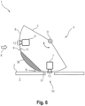
- Fig.6 shows a sectional view in side view of a variant of the cooking appliance 1 in the area of the support 5.
- a forced ventilation gap 37 between the outside 9 of the support wall 8 and the cooking chamber wall 2 in the area of the wall opening 10.
- the fact that the gap 37 can be forced aired can mean that a secondary air flow N of the internal cooling air flow K flows through it.
- the support wall 8 can be designed and/or arranged in such a way that it causes the secondary air flow N to branch off.
- the cover 38 can protrude slightly beyond the outer side 9, so that when the carrier 5 is in the position of rest and consequently the cover 38 is opposite the wall opening 10, the gap 37 is closed.
- Fig.6 can alternatively or in addition to the arrangement according to Fig.5 used and serves the same purpose.
- Fig.7 shows a sketch of a section of a cooking appliance 41 in the area of a changing device 42 as a sectional side view. on each of which a sensor unit is arranged, for example the optical camera 6 and the IR camera 7 here.
- the supports 43 and 44 can thus be rotated or pivoted between their folded-up, standby position and their folded-down, active position (in which the camera 6 or 7 is arranged on the wall opening 10).
- a further carrier can be present, which is designed as a cover or has a cover 4 . If this support is folded down, the cover closes the wall opening 10 and the changing device 42 is in its rest position. The more than two carriers are then advantageously arranged in a ring around the wall opening 10 .
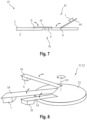
- Fig.8 shows a highly simplified sketch of a changing device 52 of a cooking appliance 51 in a view obliquely from above.
- the changing device 52 now has a circular disk-shaped base (“base disk”) 53 that can be rotated by motor about a first, here vertical axis of rotation D1.
- base disk On the base plate 53, three radially aligned, pivotable carriers (“arms”) 54 are attached at an angular offset about the axis of rotation D1.
- the cameras 6 and 7 and a cover 55 are arranged on the undersides of the free end sections of the cantilevers 54 .
- the cameras 6 and 7 are therefore aligned essentially parallel to the first axis of rotation D1.
- the base plate 53 positions the arms 54, which can then be flexibly raised and lowered according to the space available in the cooking appliance 51.
- This movement of the cantilevers 54 about a respective horizontal second axis of rotation can also be referred to as a pitching movement.
- the extension arms 54 Due to their individually adjustable pitching movement, the extension arms 54 can avoid obstacles while the base plate 53 is rotating (e.g. by temporarily lowering or lifting them during the rotation), in their active position they can be sufficiently lowered to the cooking chamber wall 2 and in their standby position they can be used for optimum cooling or be raised high to minimize the impact on functional spaces below (e.g. cooling air ducts).
- a numerical specification can also include exactly the specified number as well as a usual tolerance range, as long as this is not explicitly excluded.
Landscapes
- Engineering & Computer Science (AREA)
- Physics & Mathematics (AREA)
- Electromagnetism (AREA)
- Chemical & Material Sciences (AREA)
- Combustion & Propulsion (AREA)
- Mechanical Engineering (AREA)
- General Engineering & Computer Science (AREA)
- Food Science & Technology (AREA)
- Electric Ovens (AREA)
Description
- Die Erfindung betrifft ein Gargerät, aufweisend einen mittels einer Garraumwandung begrenzten Garraum, mindestens zwei außerhalb des Garraums angeordnete Sensoreinheiten und eine Öffnung in der Garraumwandung, durch welche mittels einer der mindestens zwei Sensoreinheiten mindestens eine Eigenschaft des Garraums detektierbar ist. Die Erfindung ist insbesondere vorteilhaft anwendbar auf Haushalts-Gargeräte, insbesondere Backöfen und/oder Mikrowellengeräte.
-
WO 2015/141207 A1 offenbart ein Gargerät, aufweisend einen Infrarotsensor, der außerhalb eines Garraums vorgesehen ist und der eine Vielzahl von Infrarotsensorelementen verwendet, um die Temperatur eines zu erhitzenden Objekts zu erfassen; und einen Richtungssetzmotor, der die Richtung des Infrarotsensors ändern kann. Das Gargerät ist dazu so konfiguriert, dass sich die Richtung des Infrarotsensors zu einer Temperaturerfassungsposition bewegt, wenn die Temperaturerfassung durchgeführt wird, und die Richtung des Infrarotsensors zu einer Bereitschaftsposition bewegt wird, wenn keine Temperaturerfassung durchgeführt wird. Infolgedessen ist es möglich, eine Trübung der Linse des Infrarotsensors und eine Temperaturerhöhung des Infrarotsensors selbst zu verhindern. So ist es beispielsweise möglich, den Infrarotsensor in einem Zustand zu halten, in dem es möglich ist, die Temperatur auch direkt nach einer Dampferhitzung zu erfassen. -
EP 0 924 964 A2 offenbart einen Mikrowellenherd mit einem Infrarotsensor zum Erfassen der Temperatur von Speisen während des Garens. Der Infrarotsensor ist von der oberen Vorderkante des Garraums schräg nach unten und nach hinten gerichtet. Ein Verschluss oder Blende schützt den Sensor, wenn er nicht zum Erfassen der Lebensmitteltemperatur benötigt wird. - Es ist die Aufgabe der vorliegenden Erfindung, die Nachteile des Standes der Technik zumindest teilweise zu überwinden und insbesondere eine verbesserte Möglichkeit bereitzustellen, Messwerte eines Garraums oder eines in dem Garraum befindlichen Garguts abzufühlen.
- Diese Aufgabe wird gemäß den Merkmalen der unabhängigen Ansprüche gelöst. Vorteilhafte Ausführungsformen sind Gegenstand der abhängigen Ansprüche, der Beschreibung und der Zeichnungen.
- Die Aufgabe wird gelöst durch ein Gargerät, aufweisend einen mittels einer Garraumwandung begrenzten Garraum, mindestens zwei außerhalb des Garraums angeordnete Sensoreinheiten und eine Öffnung in der Garraumwandung (im Folgenden auch als "Wandungsöffnung" bezeichnet), durch welche mittels einer der mindestens zwei Sensoreinheiten mindestens eine Eigenschaft des Garraums detektierbar ist, wobei
- außerhalb des Garraums eine motorisch bewegbare Vorrichtung ("Wechselvorrichtung") vorhanden ist,
- die Wechselvorrichtung mit mindestens zwei Sensoreinheiten zur Detektion mindestens einer Eigenschaft des Garraums ausgerüstet ist und
- die Wechselvorrichtung durch motorische Bewegung so einstellbar ist, dass jeweils eine der Sensoreinheiten vor die Öffnung verbringbar ist.
- Dieses Gargerät ergibt den Vorteil, dass die Wandungsöffnung zeitlich versetzt durch unterschiedliche Sensoreinheiten verwendet werden kann. So kann eine besonders vorteilhafte Sensorposition für alle diese Sensoreinheiten genutzt werden. Ein weiterer Vorteil für den Fall, dass mindestens zwei der Sensoreinheiten bildgebende Sensoreinheiten sind (z.B. eine optische Kamera und eine IR-Kamera), besteht darin, dass die Bilder dieser Sensoren ohne weitere Anpassung überlagert werden können, da beide den Garraum bzw. das Gargut aus der gleichen Perspektive abbilden. Es befindet sich jeweils nur die gerade benötigte Sensoreinheit an der Wandungsöffnung, so dass die nicht verwendeten Sensoreinheiten vor Verschmutzung (z.B. Wrasen, Fettspritzern usw.) und/oder Einstrahlung von Wärmestrahlen aus dem Garraum durch die Wandungsöffnung geschützt sind. Noch ein weiterer Vorteil besteht darin, dass durch das Vorsehen nur einer Wandungsöffnung für mehrere Sensoreinheiten ein Wärmeverlust aus einem heißen Garraum besonders gering gehalten werden kann.
- Das Gargerät ist vorteilhafterweise ein Haushalts-Gargerät. Das Gargerät ist insbesondere ein Backofen, ein Mikrowellengerät oder eine Kombination davon, z.B. ein Backofen mit Mikrowellenfunktion. Das Gargerät kann auch eine Dampfbehandlungsfunktion aufweisen. Es ist eine Weiterbildung, dass der Garraum eine vorderseitige Beschickungsöffnung aufweist, die mittels einer Tür verschließbar ist. Insbesondere bei Vorliegen eines Backofens kann die geräteinterne Garraumwandung (ohne Tür) auch als Muffel bezeichnet werden.
- Die Sensoreinheit kann ein oder mehrere einzelne Sensorelemente aufweisen. Die Sensoreinheit ist insbesondere eine separat hergestellte Einheit, die an der Wechselvorrichtung befestigt ist.
- Es ist eine Weiterbildung, dass die Wandungsöffnung insbesondere eine freie oder durchlässige Öffnung ist, d.h., eine Öffnung, die nicht permanent mittels einer Scheibe (z.B. einer transparenten Glasscheibe) o.ä. abgedeckt ist. Dies ermöglicht vorteilhafterweise eine hochgradig unbeeinflusste Detektion oder Messung der mindestens einen Eigenschaft des Garraums. Alternativ kann die Wandungsöffnung permanent von einer Schutzscheibe abgedeckt sein, wenn diese für alle Sensoreinheiten messtechnisch durchlässig ist, also eine Messung der zugehörigen mindestens einen Eigenschaft des Garraums für alle Sensoreinheiten zulässt. Umfassen die Sensoreinheiten beispielsweise ein optische Kamera und eine IR-Kamera, kann eine permanente Schutzscheibe in Form einer für das optische und das betreffende IR-Spektrum (z.B. NIR-Spektrum) durchsichtigen, insbesondere transparenten Scheibe vorhanden sein.
- Die mindestens eine Eigenschaft des Garraums kann beispielsweise eine physikalische Größe wie eine Helligkeits- und/oder Farbverteilung auf einer Gargutoberfläche (z.B. zur Bestimmung eines Bräunungsgrads von Gargut), eine Temperatur des Garraums, eine Temperaturverteilung auf einer oder mehreren Gargutoberflächen, eine Feuchtigkeit in dem Garraum usw. und/oder eine chemische Größe wie ein Anteil eines oder mehrerer chemischer Stoffe an einer Garraumatmosphäre, z.B. einen Sauerstoffanteil usw., umfassen. Eine Eigenschaft des Garraums kann somit beispielsweise eine Eigenschaft der Garraumatmosphäre und/oder eine Eigenschaft von in dem Garraum befindlichem Gargut umfassen.
- Die außerhalb des Garraums vorhandene Wechselvorrichtung ist insbesondere innerhalb des Gargeräts untergebracht, beispielsweise in einem Zwischenraum zwischen der Garraumwandung und einem äußeren Gehäuse des Gargeräts. Es ist eine Weiterbildung, dass die Wechselvorrichtung oberhalb des Garraums angeordnet ist, weil dort besonders viel Platz zu dessen Unterbringung vorhanden ist.
- Die Wechselvorrichtung ist insbesondere mittels mindestens eines Antriebsmotors wie eines Elektromotors, insbesondere Schrittmotors, motorisch verfahrbar.
- Dass durch Bewegen der Wechselvorrichtung (als Ganzes oder eines Teils davon) jeweils eine der Sensoreinheiten vor die Wandungsöffnung bewegbar oder verbringbar ist, umfasst insbesondere, dass jeder der Sensoreinheiten eine bestimmte Stellung (im Folgenden auch als "Aktivstellung" bezeichnet) zugeordnet ist, in welcher diese Sensoreinheit mindestens eine zugehörige Eigenschaft des Garraums durch die Wandungsöffnung detektieren kann. Dabei kann sich pro Zeitabschnitt nur jeweils eine der Sensoreinheiten vor der Wandungsöffnung befinden. Die anderen Sensoreinheiten sind dagegen von der Wandungsöffnung entfernt angeordnet (was im Folgenden auch als "Standby-Stellung" bezeichnet wird) und können diese nicht nutzen. Mittels der Wechselvorrichtung sind also die daran vorhandenen Sensoreinheiten wechselweise einzeln vor die Wandungsöffnung in der Garraumwandung bewegbar.
- Es ist eine Weiterbildung, dass der Motor mit einer Steuereinrichtung des Gargeräts verbunden ist, um die jeweilige Sensoreinheit bei Bedarf automatisch - z.B. programmgesteuert und/oder situationsabhängig, z.B. ereignisgesteuert - vor die Wandungsöffnung zu verbringen.
- Es ist eine Ausgestaltung, dass die Wechselvorrichtung mehrere motorisch verfahrbare Träger aufweist, an denen jeweils eine Sensoreinheit angeordnet ist. Diese Ausgestaltung weist den Vorteil auf, dass sie besonders vielgestaltig ausbildbar ist. Die Träger können insbesondere jeweils zwei Positionen oder Stellungen dauerhaft einnehmen, nämlich die Aktivstellung und die Standby-Stellung. Die Träger können wechselweise in ihre Aktivstellung verbracht werden. Es ist eine Weiterbildung, dass die Träger zwischen ihrer Aktivstellung und ihrer Standby-Stellung umgeklappt werden können. Es ist eine Weiterbildung, dass die Träger, insbesondere umklappbare Träger, ringförmig um die Wandungsöffnung angeordnet sind. Dabei kann in einer Weiterbildung jeder der Träger mit einem zugehörigen Motor verbunden sein. Alternativ können alle Träger mittels eines einzigen Motors bewegbar sein.
- Es ist eine Ausgestaltung, dass die Wechselvorrichtung einen motorisch verfahrbaren Träger aufweist, an dem die mindestens zwei Sensoreinheiten angeordnet sind. Dieser Träger ist also ein gemeinsamer Träger für die mindestens zwei Sensoreinheiten. Bei Bewegung dieses gemeinsamen Trägers werden alle daran angeordneten Sensoreinheiten mitbewegt. Diese Ausgestaltung lässt sich besonders einfach, robust und preiswert umsetzen.
- Es ist eine Ausgestaltung, dass mindestens eine der Sensoreinheiten
- einen optischen Sensor,
- einen Temperatursensor,
- einen Feuchtigkeitssensor und/oder
- einen Stoffsensor
- Der optische Sensor kann eine optische Kamera, z.B. eine bildgebende Digitalkamera sein, insbesondere eine Farbkamera. Der Temperatursensor kann ein Temperaturfühler oder eine bildgebende Wärmebild (IR)-Kamera sein. Der Stoffsensor kann ein Sauerstoffsensor sein, z.B. eine Lambdasonde. Der Stoffsensor kann ein Spektrometer sein.
- Es ist eine Ausgestaltung, dass die Wechselvorrichtung zusätzlich mit mindestens einer vor die Wandungsöffnung bewegbaren oder verbringbaren Abdeckung ausgerüstet ist. Dadurch wird der Vorteil erreicht, dass die Öffnung in der Garraumwandung verschließbar ist und die Sensoreinheiten vor Einflüssen aus dem Garraum wie Wärme (z.B. während eines Garvorgangs oder eines Pyrolysevorgangs) und/oder Verschmutzung geschützt sind und darüber hinaus ein Wärmeverlust aus einem heißen Garraum ganz besonders gering gehalten werden kann.
- Es ist eine Weiterbildung, dass die Wechselvorrichtung so einstellbar ist, dass die Abdeckung anstelle der Sensoreinheiten vor die Wandungsöffnung verbringbar ist. Insbesondere kann die Abdeckung analog zu einer Sensoreinheit angeordnet und bewegbar sein. So kann für den Fall, dass die Wechselvorrichtung mehrere motorisch verfahrbare Träger aufweist, an einem der Träger die Abdeckung anstelle einer Sensoreinheit vorhanden sein. Für den Fall, dass die Wechselvorrichtung einen motorisch verfahrbaren Träger aufweist, an dem die mindestens zwei Sensoreinheiten angeordnet sind, kann an dem Träger auch die Abdeckung vorhanden sein.
- Die an dem Träger vorgesehene Abdeckung kann ein separat hergestelltes Bauteil oder ein integraler Teilbereich des Trägers sein.
- Es ist eine Weiterbildung, dass die Wechselvorrichtung zusätzlich oder alternativ zu der oben beschriebenen, an einem Träger befestigten Abdeckung eine weitere vor die Wandungsöffnung bewegbare Abdeckung in Form einer Schutzscheibe aufweist, wobei diese Schutzscheibe (im Gegensatz zu einer permanent vor der Wandungsöffnung befestigten Schutzscheibe) für mindestens eine der Sensoreinheiten messtechnisch durchlässig ist, also eine Messung der zugehörigen mindestens einen Eigenschaft des Garraums zulässt, und für mindestens eine andere der Sensoreinheiten messtechnisch undurchlässig ist. Ist beispielsweise eine der Sensoreinheiten eine optische Kamera und eine andere der Sensoreinheiten eine IR-Kamera, kann die bewegbare Schutzscheibe eine im optischen Bereich durchlässige, aber im IR-Bereich nicht oder nicht ausreichend durchlässige Scheibe (z.B. eine Glasscheibe) sein. Die Wechselvorrichtung kann so eingerichtet sein oder angesteuert werden, dass die Schutzscheibe dann die Wandungsöffnung überdeckt, wenn sich eine Sensoreinheit vor der Wandungsöffnung befindet, für welche die Schutzscheibe messtechnisch durchlässig ist, und die Wandungsöffnung freigibt, wenn sich eine Sensoreinheit vor der Wandungsöffnung befindet, für welche die Schutzscheibe messtechnisch undurchlässig ist. Es ist also eine Weiterbildung, dass die Schutzscheibe die Wandungsöffnung nur bedarfsweise überdeckt oder nur bedarfsweise von der (dann zeitweise freien) Wandungsöffnung entfernt wird. Auch die Bewegung der Schutzscheibe kann motorisch erfolgen.
- Es ist eine Ausgestaltung, dass die Garraumwandung im Bereich der Wandungsöffnung als eine - insbesondere trichter- oder kegelstumpfförmige - Ausstülpung geformt ist, die sich in Richtung des Garraums aufweitet. Die Ausstülpung kann als eigenständiges Bauteil vorgefertigt worden sein. Die Schutzscheibe kann, falls vorhanden, insbesondere vor die garraumseitige Stirnfläche der Ausstülpung bewegt werden. Die Wandungsöffnung kann insbesondere der garraumabgewandten Stirnfläche der Ausstülpung entsprechen.
- Es ist eine Weiterbildung, dass diejenige Verfahrstellung, bei der die Wandungsöffnung durch die an dem Träger vorhandene Abdeckung überdeckt ist, eine "Normalstellung" oder "Ruhestellung" der Wechselvorrichtung ist und die anderen Sensoreinheiten nur bei Bedarf vor die Wandungsöffnung verfahren werden und folgend wieder die Normalstellung eingenommen wird. Dadurch werden die Sensoreinheiten vorteilhafterweise nur an die Öffnung herangebracht und damit dem heißen und/oder (z.B. durch Fettspritzer, Flüssigkeitsspritzer oder Wrasen) schmutzigen Garraum ausgesetzt, wenn eine Messung notwendig ist. In einer Weiterbildung wird die Wechselvorrichtung unmittelbar nach Ablauf der Messzeit der sich vor der Öffnung befindlichen Sensoreinheit wieder in die Ruhestellung zurückgefahren und die Sensoreinheit dadurch wieder in eine geschützte Position gebracht. Die Expositionszeit für die Sensoreinheiten ist dadurch gering, was auch für den Wärmeverlust aus dem heißen Garraum gilt.
- Es ist eine Weiterbildung, dass die Wechselvorrichtung zumindest mit einer bildgebenden Digitalkamera und einer bildgebenden IR-Kamera versehen oder bestückt ist und insbesondere auch eine Abdeckung aufweist oder bereitstellt.
- Es ist eine insbesondere für den Fall, dass die Wechselvorrichtung einen motorisch bewegbaren Träger aufweist, an dem die mindestens zwei Sensoreinheiten angeordnet sind, eine vorteilhafte Ausgestaltung, dass der Träger motorisch drehbar ist und dessen Winkelstellungen so einstellbar sind, dass durch Drehung des Trägers jeweils eine der Sensoreinheiten vor die Öffnung verbringbar ist. So wird der Vorteil erreicht, dass eine besonders kompakte und robuste Anordnung bereitgestellt werden kann. Für den Fall, dass an dem Träger auch eine Abdeckung vorhanden ist, kann diese analog zu den Sensoreinheiten angeordnet sein. Dabei kann der Träger z.B. über eine Antriebswelle mit einem Motor bzw. mit einer Antriebswelle des Motors verbunden sein. Durch Drehung der Antriebswelle lassen sich gezielt vorgegebene Winkelstellungen des Trägers um seine Drehachse einstellen.
- Der Träger kann innerhalb eines begrenzten Winkelbereichs, d.h., in einem Winkelbereich kleiner 360°, drehbar sein oder kann alternativ umlaufend drehbar sein. Der Träger kann über eine Antriebswelle mit dem Motor bzw. mit einer Antriebswelle des Motors verbunden sein. Durch Drehung des Motors lassen sich gezielt vorgegebene Winkelstellungen des Trägers um seine Drehachse einstellen. Dass durch Drehung des Trägers jeweils eine der Sensoreinheiten vor die Öffnung verbringbar ist, umfasst insbesondere, dass jeder der Sensoreinheiten eine bestimmte Winkelstellung zugeordnet ist, in welcher diese Sensoreinheit mindestens eine zugehörige Eigenschaft des Garraums durch die Öffnung detektieren kann.
- Es ist eine Ausgestaltung, dass die Sensoreinheiten (und ggf. die Abdeckung) bogenförmig um eine Drehachse des Trägers angeordnet sind. So wird vorteilhafterweise erreicht, dass sie durch einfache Drehung präzise an der Wandungsöffnung positionierbar sind. Die bogenförmige Anordnung kann eine kreis- oder ringsektorförmige Anordnung sein.
- Es ist eine Ausgestaltung, dass die Sensoreinheiten (und ggf. die Abdeckung) in Bezug auf die Drehachse des Trägers radial nach außen ausgerichtet sind. Dies ergibt den Vorteil einer besonders einfachen und kompakten Anordnung. Diese Ausgestaltung umfasst insbesondere, dass ein Mess- oder Sichtfeld der Sensoreinheiten radial zu der Drehachse ausgerichtet ist. Beispielweise kann eine optische Achse einer Kamera in Bezug auf die Drehachse des Trägers radial nach außen ausgerichtet sein.
- Es ist eine Weiterbildung davon, dass die Drehachse des Trägers zumindest annähernd parallel zu einer die Wandungsöffnung aufweisenden Wand der Garraumwandung ausgerichtet ist. In anderen Worten ist die Drehachse des Trägers zumindest annähernd senkrecht zu einer Normalenrichtung der Wandungsöffnung ausgerichtet.
- Die Wand der Garraumwandung, in der sich die Wandungsöffnung befindet, kann allgemein beispielsweise eine Decke, eine Rückwand, eine linke Seitenwand, eine rechte Seitenwand oder eine Rückwand sein. Die Wandungsöffnung kann sich auch in einem Übergang zwischen solchen Wänden befinden. Die Wand der Garraumwandung kann auch die den Garraum verschließende Tür umfassen, da diese im geschlossenen Zustand ebenfalls einen Bereich oder eine Seite der Garraumwandung darstellt. Es ist somit eine Weiterbildung, dass die Wechselvorrichtung einschließlich der daran angebrachten Sensoreinheiten in einer Tür des Gargeräts untergebracht ist. Dies ergibt den Vorteil, dass ein Betrachtungswinkel aus der geschlossenen Tür in etwa dem Betrachtungswinkel eines Nutzers entspricht, wenn er die Tür zum Nachschauen öffnet.
- Es ist eine alternative Ausgestaltung, dass die Sensoreinheiten parallel zu der Drehachse des Trägers ausgerichtet sind, beispielsweise nach Art eines Revolvers. Die Drehachse des Trägers liegt dann insbesondere zumindest ungefähr senkrecht versetzt zu einer die Öffnung aufweisenden Wand der Garraumwandung bzw. zumindest ungefähr parallelversetzt zu einer Normalenrichtung der Wandungsöffnung.
- Es ist eine Ausgestaltung, dass der Träger eine bogensektorförmig, insbesondere ringsektorförmig, um seine Drehachse angeordnete bandförmige Trägerwand aufweist, wobei an der Trägerwand zueinander winkelversetzt mindestens zwei Bestückplätze für Sensoreinheiten vorhanden sind. So wird vorteilhafterweise eine besonders einfach herstellbare und robuste Möglichkeit bereitgestellt, die Sensoreinheiten an dem Träger zu befestigen. Ist eine separat hergestellte Abdeckung vorhanden, kann für diese ebenfalls ein Bestückplatz vorgesehen sein. Eine separat hergestellte Abdeckung ergibt den Vorteil, dass sie im Vergleich zu dem Material des Trägers (z.B. Kunststoff) auf besonders einfache Weise aus besonders hitzebeständigem Material herstellbar ist, z.B. aus Keramik oder verspiegeltem Metall. Alternativ kann die Abdeckung in den Träger integriert sein, für welchen Fall kein speziell ausgestalteter Bestückplatz vorgesehen zu sein braucht.
- Alternativ zu einem motorisch drehbaren Träger kann der Träger motorisch translatorisch, insbesondere linear, verfahrbar oder verschiebbar sein. Anstelle einer bogenförmigen Trägerwand kann diese dann z.B. als ebenes Band oder Platte ausgebildet sein und z.B. parallel zu der die Öffnung aufweisenden Garraumwand bewegbar sein.
- Die Ausbildung als ebene Platte kann aber auch vorteilhaft sein, wenn die Sensoreinheiten parallel zu der Drehachse des drehbaren Trägers ausgerichtet sind. Die Trägerwand kann dann z.B. als kreisförmige oder kreissektorförmige Platte ausgebildet sein.
- Es ist eine Ausgestaltung, dass
- eine Außenseite der Trägerwand vor der Öffnung in der Garraumwandung entlang bewegbar ist und
- an einer Innenseite der Trägerwand zueinander versetzt mindestens zwei Bestückplätze für Sensoreinheiten vorhanden sind, die jeweils eine Befestigungsstruktur für eine zugehörige Sensoreinheit aufweisen.
- So wird der Vorteil erreicht, dass die Sensoreinheiten einfach an dem Träger befestigbar sind und auch ohne Justage präzise vor die Öffnung in der Garraumwandung bewegbar sind. Dass eine Außenseite der Trägerwand vor der Öffnung in der Garraumwandung entlang bewegbar ist, umfasst insbesondere, dass sich die Trägerwand (aus Sicht des Trägers) vor der Wandungsöffnung entlang ihrer Längserstreckung drehen oder translatorisch bewegen kann. Die Trägerwand verbleibt dabei insbesondere vor der Öffnung, jedoch je nach Stellung mit einem anderen Abschnitt. Die Längserstreckung der Trägerwand entspricht für den Fall, dass der Träger drehbar ist und die Sensoreinheiten in Bezug auf die Drehachse des Trägers radial nach außen ausgerichtet sind, ihrer Bewegungsrichtung, beispielsweise bei Drehbarkeit einer Umfangsrichtung der Drehachse.
- Es ist eine Ausgestaltung, dass zumindest einer der Bestückplätze ein mit der Wandungsöffnung in der Garraumwandung in Deckung bringbares Fenster aufweist. Durch das in Überdeckung Bringen des Fensters mit der Wandungsöffnung kann für die jeweilige Sensoreinheit die Einsicht in den Garraum bereitgestellt werden. Das Fenster kann z.B. ein Durchbruch oder Loch in der Trägerwand sein. Es ist eine Weiterbildung, dass alle für Sensoreinheiten vorgesehene Bestückplätze (im Folgenden auch als "Sensor-Bestückplätze" bezeichnet) ein solches Fenster aufweisen.
- Die Sensoreinheiten können in grundsätzlich beliebiger Reihenfolge an der Trägerwand angeordnet sein.
- Es ist eine Ausgestaltung, dass mindestens zwei Bestückplätze bzw. die zugehörigen Sensoreinheiten durch eine Abdeckung voneinander getrennt sind, sich die Abdeckung in Bewegungsrichtung des Trägers, insbesondere der Trägerwand, also insbesondere zwischen den mindestens zwei Bestückplätzen befindet. So wird der Vorteil erreicht, dass eine nur geringe Bewegung oder Verfahrung nötig ist, um Bestückplätze bzw. die in diesen vorhandenen Sensoreinheiten aus der Ruhestellung vor die Wandungsöffnung zu bringen.
- Es ist eine Ausgestaltung, dass mindestens zwei Bestückplätze bzw. die zugehörigen Sensoreinheiten nebeneinander an einem Endabschnitt der Trägerwand angeordnet sind und die Abdeckung an dem anderen Endabschnitt angeordnet ist. Dadurch wird der Vorteil erreicht, dass die Bestückplätze bzw. die zugehörigen Sensoreinheiten in der Ruhestellung des Trägers, bei der die Wandungsöffnung durch die Abdeckung abgedeckt ist, vergleichsweise weit von der Garraumwandung entfernt positioniert sind und folglich besonders geringen Temperaturen ausgesetzt sind.
- Es ist eine Ausgestaltung, dass die Sensoreinheiten in dem Gargerät belüftbar angeordnet sind. Dadurch können sie vorteilhafterweise während eines Garbetriebs gekühlt werden. Es ist eine Weiterbildung, dass das Gargerät mindestens einen Lüfter oder Ventilator aufweist, mittels dessen in dem Gargerät (typischerweise zwischen der Garraumwandung und einem Gehäuse des Gargeräts) ein geräteinterner Kühlluftstrom (forciert) erzeugbar ist. Ein solcher Kühlluftstrom kann ein Kühlluftstrom sein, der bereits zur Kühlung anderer Bereiche genutzt wird oder worden ist, z.B. zur Kühlung einer Elektronik und/oder zur Türkühlung. Ein solcher Kühlluftstrom kann aber auch ein eigenständiger, insbesondere auch separater Kühlluftstrom sein, der von außen zu der Wechselvorrichtung, insbesondere zu deren Sensoreinheiten, führt. Eine verbesserte Kühlung der Sensoreinheiten ergibt sich allgemein dann, wenn Kühlluft direkt von außen oder von einem kühleren Bodenbereich des Geräts zu den Sensoreinheiten geführt wird. Insbesondere können die Sensoreinheiten in dem geräteinternen Kühlluftstrom angeordnet sein. Es ist eine Weiterbildung, dass der Träger dazu luftdurchlässig ausgebildet ist, beispielweise durch Vorsehen geeigneter Durchbrüche, Schlitze usw. Alternativ kann die Trägerwand mit der Drehachse über eine Rahmenkonstruktion verbunden sein.
- Es ist eine Weiterbildung, dass ein Bestückplatz eine an einem Fenster in einer Trägerwand innenseitig ansetzende Hülse aufweist, In diese Hülse kann rückwärtig ein dem Garraum zugewandter Bereich einer Sensoreinheit eingesetzt, insbesondere eingesteckt, werden, oder die Sensoreinheit kann an die Hülse angesetzt (aber nicht eingeführt) werden. Eine vordere offene Stirnfläche der Hülse kann dem Fenster entsprechen, während die hintere oder rückwärtige offene Stirnfläche als Ansatz- oder Einsetzöffnung für die Sensoreinheit vorgesehen ist. Ist die Sensoreinheit eine Kamera, kann z.B. deren Objektiv rückseitig an die Hülse angesetzt (z.B. auf die Hülse aufgesetzt) werden oder in die Hülse eingesetzt werden. Der an oder in der Hülse befindliche Bereich der Sensoreinheit ist in der Regel derjenige Bereich, der am stärksten der aus der Wandungsöffnung einfallenden Wärmestrahlung und zudem Verschmutzungen wie Flüssigkeits- oder Fettspritzern ausgesetzt ist. Die Hülse kann daher vorteilhafterweise als Positionierungshilfe und Abstandshalter für die zugehörige Sensoreinheit dienen. Die Hülse kann seitlich oder mantelseitig durchbrochen sein, um eine Querung der Hülse durch den Kühlluftstrom zu ermöglichen. Ist die Sensoreinheit in die Hülse eingesetzt oder angesetzt, kann der durch die Hülse geleitete Luftstrom eine Kühlung der zugehörigen Sensoreinheit bewirken. Die Hülse ermöglicht somit vorteilhafterweise eine einfache Positionierung der zugehörigen Sensoreinheit an dem Träger und deren Kühlung in Aktiv- und Standby-Stellung.
- Um die Sensoreinheit besonders effektiv zu schützen, ist es eine Weiterbildung, dass die Hülse als Luftstromsammler ausgebildet ist oder mit einem Luftstromsammler verbunden ist. Der Luftstromsammler befindet sich in dem Kühlluftstrombereich des Gargeräts und ist so geformt und ausgerichtet, dass er einen Teil des Kühlluftstroms gezielt in die Hülse leitet. Auf der entgegengesetzten Seite der Hülse kann sie eine Luftauslassöffnung aufweisen. Folglich ermöglicht der Luftstromsammler einen besonders zuverlässigen, die Hülse querenden Luftstrom.
- Es ist eine Weiterbildung, dass der Luftstromsammler einen sich in Strömungsrichtung der eintretenden Luft verengenden Strömungsquerschnitt aufweist. Dadurch wird eine Strömungsgeschwindigkeit der Kühlluft in der Hülse erhöht, was eine Kühlwirkung verstärkt. Auch kann der Kühlluftstrom so stark sein, dass er nun eintretende Fett- und Flüssigkeitsspritzer vor der Sensoreinheit ablenkt. Der Luftstromsammler ermöglicht somit vorteilhafterweise eine einfache Positionierung der zugehörigen Sensoreinheit an dem Träger, deren Kühlung in Aktiv- und Standby-Stellung und einen Verschmutzungsschutz in Aktivstellung. Der Luftstromsammler kann beispielsweise trichterförmig sein, mit seiner breiteren Öffnung gegen die Richtung des Kühlluftstroms gerichtet sein und mit seiner schmaleren Öffnung seitlich in die Hülse münden. Auf der entgegengesetzten Seite kann die Hülse eine Luftauslassöffnung aufweisen.
- Es ist eine Ausgestaltung, dass zwischen der Trägerwand im Bereich der Fenster und der Garraumwandung im Bereich der Öffnung ein insbesondere forciert belüftbarer Spalt vorhanden ist, durch den ein Luftstrom geführt werden kann. So wird ebenfalls der Vorteil erreicht, dass eine sich in ihrer Aktivstellung befindliche Sensoreinheit vor Verschmutzung aus dem Garraum geschützt wird und gekühlt wird.
- Es ist eine Weiterbildung, dass die Abdeckung die Öffnung in der Garraumwandung spaltfrei überdeckt. Befinden sich also alle Sensoreinheiten in ihrer Standby-Position (was einer Ruhestellung des Trägers bzw. der Wechselvorrichtung entspricht) können mittels der Abdeckung zeitgleich die Garraumöffnung und der Luftkanal abgeschlossen werden. Dazu kann die Abdeckung z.B. außenseitig an einer Trägerwand überstehen, insbesondere mit einer Höhe, welche der Spaltbreite entspricht oder fast entspricht.
- Grundsätzlich kann die Wechselvorrichtung auch translatorische Bewegungen und Drehbewegungen kombinieren und/oder sie kann Drehbewegungen einer Sensoreinheit um mehrere unterschiedliche Drehachsen ermöglichen. Beispielsweise kann eine Wechselvorrichtung eine um eine erste - insbesondere vertikale - Drehachse motorisch drehbare - beispielsweise kreisscheibenförmige - Basis aufweisen, an der mehrere Ausleger drehbar oder verschwenkbar angebracht sind, wobei an jedem der Ausleger eine Sensoreinheit angebracht ist. Die Drehachsen der Ausleger können jeweils zu der Drehachse der Basis senkrecht ausgerichtet sein, z.B. in horizontaler Richtung, und zueinander winkelversetzt oder verkippt sein, z.B. in Umfangsrichtung der ersten Drehachse.
- Die Aufgabe wird auch gelöst durch ein Verfahren zum Betreiben eines Gargeräts wie oben beschrieben. Das Verfahren kann analog zu dem Gargerät ausgebildet werden und weist die gleichen Vorteile auf.
- So ist es eine Ausgestaltung, dass während eines Garbetriebs zumindest eine der Sensoreinheiten bei Bedarf durch Bewegung der Wechselvorrichtung aus einer Standby-Stellung in eine Aktivstellung gebracht wird, mittels dieser Sensoreinheit in der Aktivstellung eine Messung durchgeführt wird und diese Sensoreinheit nach der Messung durch Bewegung der Wechselvorrichtung unmittelbar wieder in die Standby-Stellung verbracht wird. Dadurch wird vorteilhafterweise eine Expositionszeit der Sensoreinheiten gegenüber dem Garraum besonders gering gehalten.
- Ist eine der Sensoreinheiten eine optische Kamera, kann diese in einer Weiterbildung zu Beginn eines Garvorgangs eingesetzt werden, um in dem Garraum befindliches Gargut zu erkennen, zu vermessen und/oder bildlich darzustellen. In noch einer Weiterbildung wird die optische Kamera anschließend nur noch in größeren Zeitabständen (z.B. von einer bis fünf Minuten) für eine kurze Zeitdauer zur Aufnahme eines Bilds benötigt, um einen Garfortschritt des Garguts festzustellen. Wird die optische Kamera nur zur Bildaufnahme vor die Wandungsöffnung bewegt und nach Bildaufnahme unmittelbar wieder in die Standby-Stellung verbracht, sind die thermische Belastung und die Verschmutzungsgefahr stark verringert. Die optische Kamera kann dann vorteilhafterweise sehr preisgünstig ausgeführt sein.
- Eine bildgebende IR-Kamera mag insbesondere bei einem Mikrowellenbetrieb (einer schnellen Betriebsart, die typischerweise eine kurze Gardauer aufweist) in regelmäßigen Zeitabständen für eine Aufnahme in die Aktivposition verfahren und dann wieder in die Standby-Stellung gefahren werden, in der sie thermisch gekühlt werden kann und vor Verschmutzung geschützt ist.
- Allgemein können während eines Garvorgangs wechselweise mehrere (unterschiedliche) Sensoreinheiten mittels der Wechselvorrichtung in die Aktivstellung bewegt werden. In einer Weiterbildung wird während eines Garvorgangs nur eine der Sensoreinheiten mittels der Wechselvorrichtung in die Aktivstellung bewegt, z.B. eine optische Kamera während eines Garbetriebs unter Verwendung von IR-Strahlungskörpern wie Widerstandsheizkörpern und eine IR-Kamera während eines Mikrowellenbetriebs. Dazu kann das Gargerät beispielsweise ein Backofen mit Mikrowellenfunktionalität sein.
- Allgemein wird mittels des vorliegenden Gargeräts die wechselweise oder zeitdiskrete Nutzung verschiedener Sensoreinheiten an einem gemeinsamen Ort ausgenutzt. Das ist insbesondere für Sensoreinheiten vorteilhaft, deren Auswertung keinen kontinuierlichen oder quasi-kontinuierlichen Datenstrom mit möglichst vielen Messungen pro Zeiteinheit über einen längeren Zeitraum voraussetzt. So benötigt die Auswertung von Bildinformationen für Messzwecke (z.B. eine IR-Auswertung von Temperaturverläufen oder eine optische Erkennung von Gargut oder Lichtprojektionsmustern) keinen kontinuierlichen Datenstrom mit möglichst vielen Bildern pro Zeiteinheit über einen längeren Zeitraum, wie dies typischerweise bei Bildübertragung bewegter Sequenzen (Film) notwendig wäre.
- Dem Vorsehen der Wechselvorrichtung steht nicht entgegen, dass mittels anderer, nicht an der Wechselvorrichtung angeordneter Sensoren oder Sensoreinrichtungen ebenfalls mindestens eine, insbesondere weitere Eigenschaft des Garraums permanent detektierbar ist. Beispielsweise kann ein Temperatursensor zum Abfühlen einer Garraumtemperatur so angeordnet sein (beispielsweise in dem Garraum), dass er die Garraumtemperatur kontinuierlich oder quasi-kontinuierlich messen kann und die Wechselvorrichtung eine optische Kamera und eine IR-Kamera aufweist. Auch kann ein Feuchtigkeitssensor und/oder mindestens ein chemischer Sensor je nach technischer Vorgabe permanent oder an der Wechselvorrichtung vorgesehen sein.
- Die oben beschriebenen Eigenschaften, Merkmale und Vorteile dieser Erfindung sowie die Art und Weise, wie diese erreicht werden, werden klarer und deutlicher verständlich im Zusammenhang mit der folgenden schematischen Beschreibung eines Ausführungsbeispiels, das im Zusammenhang mit den Zeichnungen näher erläutert wird.
- Fig.1
- zeigt als Schnittdarstellung in Seitenansicht skizzenhaft einen Ausschnitt aus einem Gargerät gemäß einem ersten Ausführungsbeispiel im Bereich einer Wechselvorrichtung, die sich in einer Ruhestellung befindet;
- Fig.2
- zeigt in einer zu
Fig.1 analogen Darstellung eine Variante des Gargeräts gemäß dem ersten Ausführungsbeispiel mit einer unterschiedlich geformten Garraumwandung; - Fig.3
- zeigt in einer zu
Fig.1 analogen Darstellung noch eine Variante des Gargeräts gemäß dem ersten Ausführungsbeispiel mit einer zusätzlichen Schutzscheibe; - Fig.4
- zeigt in einer zu
Fig.1 analogen Darstellung das Gargerät gemäß einem zweiten Ausführungsbeispiel mit einer weiteren Wechselvorrichtung in der Ruhestellung; - Fig.5
- zeigt in Schrägansicht ein Konstruktionsbeispiel eines Trägers der Wechselvorrichtung des Gargeräts gemäß dem ersten Ausführungsbeispiel;
- Fig.6
- zeigt als Schnittdarstellung in Seitenansicht skizzenhaft einen Ausschnitt aus einer Variante des Gargeräts gemäß dem ersten Ausführungsbeispiel im Bereich der Wechselvorrichtung;
- Fig.7
- zeigt als Schnittdarstellung in Seitenansicht skizzenhaft einen Ausschnitt aus einem Gargerät gemäß einem dritten Ausführungsbeispiel im Bereich einer Wechselvorrichtung; und
- Fig.8
- zeigt in einer Ansicht von schräg oben eine Wechselvorrichtung eines Gargeräts gemäß einem vierten Ausführungsbeispiel.
-
Fig.1 zeigt als Schnittdarstellung in Seitenansicht skizzenhaft einen Ausschnitt aus einem Gargerät 1, das einen mittels einer Garraumwandung 2 begrenzten Garraum 3 aufweist. Außerhalb des Garraums 3 ist eine motorisch bewegbare Wechselvorrichtung 4 vorhanden, die in ihrer Ruhestellung gezeigt ist. Die Wechselvorrichtung 4 weist hier einen um eine Drehachse D motorisch drehbaren Träger 5 auf, an dem zwei Sensoreinheiten angeordnet sind, nämlich eine optische Kamera 6 und eine IR-Kamera 7. Der Motor zur Drehung des Trägers 5 ist nicht eingezeichnet, kann aber z.B. ein Schrittmotor sein. - Der Träger 5 weist hier eine bogensektorförmig, insbesondere ringsektorförmig, um seine Drehachse D angeordnete bandförmige Trägerwand 8 auf. Eine Außenseite 9 der Trägerwand 8 ist vor einer Wandungsöffnung 10 in der Garraumwandung 2 bewegbar, insbesondere darüber hinwegbewegbar. Der die Wandungsöffnung 10 aufweisende Teilbereich der Garraumwandung 2 ist hier eine Decke des Garraums 2. Die optische Kamera 6 und die IR-Kamera 7 sind an der Innenseite 11 der Trägerwand 8 an entsprechenden Bestückplätzen 12 befestigt. Sie sind durch ein jeweiliges Fenster 13 in der Trägerwand 8 gerichtet und weisen also ein durch das jeweilige Fenster 13 betrachtbares Sichtfeld auf. Die Kameras 6 und 7 sind also ebenfalls bogenförmig um die Drehachse D des Trägers angeordnet, und zudem in Bezug auf die Drehachse D radial nach außen ausgerichtet.
- An der Trägerwand 8 ist ferner eine Abdeckung 14 vorhanden, die hier entlang der Trägerwand 8 bzw. in Umfangsrichtung der Drehachse D zwischen der optischen Kamera 6 und der IR-Kamera 7 bzw. deren Bestückplätzen 12 angeordnet ist. Die optische Kamera 6 und die IR-Kamera 7 bzw. deren Bestückplätze 12 sind also in Drehrichtung durch die Abdeckung 14 voneinander getrennt. Die optische Kamera 6, die IR-Kamera 7 und die Abdeckung 14 sind in Umfangs- oder Drehrichtung zueinander versetzt angeordnet, insbesondere äquidistant.
- Durch Drehung des Trägers 5 um die Drehachse, z.B. mittels einer nicht dargestellten Steuereinrichtung, können die optische Kamera 6, die IR-Kamera 7 und die Abdeckung 14 wechselweise vor die Wandungsöffnung 10 verbracht werden. Die Drehachse D liegt in diesem Ausführungsbeispiel parallel zu der Garraumwandung 2. Soll z.B. ein optisches Bild oder ein IR-Bild aus dem Garraum 3 aufgenommen werden, wird der Träger 5 in eine Winkelstellung gedreht, bei der das dem Bestückplatz 12 der optischen Kamera 6 bzw. der IR-Kamera 7 zugehörige Fenster 13 mit der Wandungsöffnung 10 in Deckung gebracht ist. Der Garraum 3 ist für die optische Kamera 6 oder die IR-Kamera 7 also durch das jeweilige Fenster 13 und die Wandungsöffnung 10 einsichtig. In dieser "AktivStellung" der optischen Kamera 6 bzw. der IR-Kamera 7 kann diese mindestens ein Bild aus dem Garraum 3 aufnehmen.
- Werden die optische Kamera 6 und die IR-Kamera 7 nicht gebraucht, wird der Träger 5 in seine Ruhestellung gedreht, in der sich beide Kameras 6, 7 in ihrer "Standby-Stellung" befinden. Nun überdeckt die Abdeckung 14 die Wandungsöffnung 10, insbesondere dicht. Die Abdeckung 14 ist also anstelle der Kameras 6 und 7 vor die Wandungsöffnung 10 drehbar. Die Anordnung mit der Abdeckung 14 zwischen den beiden Kameras 6 und 7 ergibt den Vorteil, dass eine nur geringe Drehung nötig ist, um die Kameras 6 und 7 aus ihrer Standby-Stellung vor die Wandungsöffnung 10 in ihre Aktivstellung zu bringen.
-
Fig.2 zeigt in einer zuFig.1 analogen Darstellung eine Variante 1a des Gargeräts 1 mit einer unterschiedlich geformten Weiterbildung 2a der Garraumwandung 2. Und zwar weist die Garraumwand 2, 2a im Bereich der Wandungsöffnung 10 eine aus dem Garraum 3 gerichtete Ausstülpung 15 oder Rücksprung auf. Die Ausstülpung 15 ist rohrförmig, insbesondere kegelstumpf- oder trichterförmig ausgebildet und weist die Wandungsöffnung 10 an ihrer innenseitigen Stirnfläche auf. Diese Variante weist den allgemeinen Vorteil auf, dass die Kameras 6, 7 (und allgemein die Sensoreinheiten) weiter weg von der ggf. heißen Garraumwand 2 positioniert sind und also in kühlerer Umgebung eingebaut sind. Auch wird so eine leichtere Kühlung ermöglicht, da sich durch den größeren Abstand zu der restlichen Garraumwandung 2 bzw. zu dem Garraum 3 ein höherer Wärmeleitwiderstand ergibt. Die Ausstülpung 15 kann durch Formung (z.B. Tiefziehen, Prägen usw.) der Garraumwandung 2 hergestellt werden. Alternativ kann die Ausstülpung 15 ein separat hergestelltes und dann mit der restlichen Garraumwandung 2 verbundenes Bauteil sein. Dadurch wird der Vorteil erreicht, dass die Ausstülpung 15 auf eine besonders effektive Reduzierung der Wärmeleitung hin ausgebildet werden kann. So kann sie z.B. aus schlecht wärmeleitender Keramik hergestellt sein. - Durch die optionale Trichter- oder Kegelstumpfform der Ausstülpung 15 wird der weitere Vorteil erreicht, dass das Sichtfeld der Kameras 6, 7 nicht oder nicht merklich eingeschränkt wird.
- Ein weiterer, für Mikrowellengeräte (z.B. eigenständige Mikrowellengeräte oder Backöfen mit zusätzlicher Mikrowellenfunktion) wichtiger Vorteil besteht darin, dass die Ausstülpung 15 als Mikrowellen-Barriere ausgebildet werden kann, da so ein Durchtritt von Mikrowellen durch die Wandungsöffnung 10 verhindert werden kann. Dazu ist die Ausstülpung15 im allgemeinen Fall ein Rohr, das so eng ist, dass keine Wellenausbreitung durch das Rohr mehr möglich ist. Die hier optionale Trichterform der Ausstülpung 15 verstärkt ihre Dichtwirkung, so dass die Mikrowellendichtigkeit bereits nach kürzerer Strecke erreicht wird.
-
Fig.3 zeigt in einer zuFig.1 analogen Darstellung noch eine Variante 1b des Gargeräts 1 mit Ausstülpung 15 und zusätzlich einer Schutzscheibe 16. Dieses Gargerät 1, 1b ist damit als eine Weiterbildung des Gargeräts 1a gezeigt, jedoch kann die Schutzscheibe 16 auch allgemein verwendet werden, z.B. mit dem Gargerät 1 ohne Ausstülpung 15. Grundsätzlich kann die Schutzscheibe 16 alternativ oder zusätzlich zu der Abdeckung 14 vorhanden sein. Die Schutzscheibe 16 besteht hier aus preiswertem, für sichtbares Licht transparentem, aber für (N)IR-Strahlung undurchlässigem Glas. Sie ist z.B. wie gezeigt garraumseitig parallel zu der Garraumwandung 2a und der Wandungsöffnung 10 motorisch bewegbar. Die Schutzscheibe 16 kann einen Teil der Wechselvorrichtung 4 darstellen oder getrennt davon ansteuerbar sein. - Die Bewegung der Schutzscheibe 16 kann beispielsweise folgendermaßen angesteuert werden: in der Ruhestellung des Trägers 5 überdeckt auch die Schutzscheibe 16 die Ausstülpung 15, nämlich deren garraumseitige Stirnfläche 17. Die Abdeckung 14 und die Schutzscheibe 16 sind dann z.B. mehrere Millimeter bis wenige Zentimeter voneinander entfernt angeordnet und insbesondere parallel zueinander ausgerichtet. Dieser doppelte Schutz vor Wärme und Verschmutzungen aus dem Garraum 3 ist insbesondere während eines Pyrolysebetriebs vorteilhaft.
- Die Schutzscheibe 16 selbst hat dabei einen doppelten Effekt: zum einen schafft sie eine Abschottung und hindert dadurch heiße Luft am Aufsteigen bis zur Sensorfläche als auch ein Eindringen von Flüssigkeits- und Fettspritzern, zum anderen kann sie aus schlecht wärmeleitendem Material ausgeführt sein (so ist z.B. Glas oder Glaskeramik im Vergleich zu Stahl schlecht wärmeleitend), womit sich ebenfalls die Wärmeleitung der Garraumwand 2a im Bereich der Ausstülpung 15 erhöht. Es ist eine Weiterbildung der Schutzscheibe 16, dass sie, wie gestrichelt angedeutet, deutlich größer ausgeführt ist, als die garraumseitige Stirnseite der Ausstülpung, also seitlich merklich über diese Stirnseite herausragt. Auf diese Weise erhöht sich der Wärmewiderstand der davon bedeckten Garraumwandung 2a, so dass weniger Wärme in Richtung der Ausstülpung 15 und der Kameras 6, 7 fließt.
- Befindet sich die optische Kamera 6 in ihrer Aktivstellung, verbleibt die dafür transparente Schutzscheibe 16 vor der Ausstülpung 15 und schützt dadurch die optische Kamera 6 vor Wärme und Verschmutzungen aus dem Garraum 3. Befindet sich die IR-Kamera 7 in ihrer Aktivstellung, ist die Schutzscheibe 16 von Ausstülpung 15 wegbewegt und gibt diese somit frei.
- Die Ausstülpung 15 kann luftdurchlässig ausgebildet sein, z.B. gelocht oder allgemein perforiert sein, um die Wärmeleitung dadurch weiter zu reduzieren. Diese Reduzierung der Wärmeleitung kann besonders effektiv sein, wenn sich die Ausstülpung 15 in einem Bereich eines Kühlluftstroms des Gargeräts 1 befindet.
-
Fig.4 zeigt in einer zuFig.1 analogen Darstellung ein Gargerät 21 mit einer Wechselvorrichtung 22 in der Ruhestellung. Das Gargerät 21 ist ähnlich zu dem Gargerät 1, 1a oder 1b ausgestaltet, jedoch sind bei der Wechselvorrichtung 22 die beiden zwei Bestückplätze 12 bzw. die beiden Kameras 6, 7 in Umfangs- oder Drehrichtung nebeneinander an einem Endabschnitt der Trägerwand 23 angeordnet sind und die Abdeckung 14 an dem anderen Endabschnitt der Trägerwand 23 angeordnet. Dadurch wird der Vorteil erreicht, dass die Kameras 6 und 7 in der Ruhestellung der Wechselvorrichtung 22 vergleichsweise weit von der Garraumwandung 2 und der Wandungsöffnung 10 entfernt positioniert sind und folglich vergleichsweise geringen Temperaturen ausgesetzt sind. -
Fig.5 zeigt in Schrägansicht ein detaillierteres Konstruktionsbeispiel des Trägers 5 der Wechselvorrichtung 4. Der Träger 5 weist ein zentrales Rohr 31 zum Aufstecken auf eine Antriebswelle des Motors auf. Die bogenförmige Trägerwand 8 weist zwei Bestückplätze 12 mit jeweils einer radial zu der Drehachse D ausgerichteten Hülse 32 auf. Eine äußere offene Stirnseite der Hülsen 32 entspricht dem jeweiligen Fenster 13. An der anderen, innenseitigen Stirnseite in die jeweilige Kamera 6 bzw. 7 ansetzbar, insbesondere deren jeweiliges Objektiv. Seitlich mündet in die Hülsen 32 jeweils ein trichterförmiger Luftstromsammler 33, der in einen Bereich eines internen Kühlluftstroms des Gargeräts 1 gerichtet ist. Auf der gegenüberliegenden Seite ist in der Hülse 32 eine Luftaustrittsöffnung 34 vorhanden. Diese Anordnung ermöglicht es, dass ein Luftstrom die jeweilige Hülse 32 quert und dadurch z.B. aus dem Garraum 3 entweichende Fett- und Flüssigkeitsspritzer ablenkt und/oder eine Temperatur an den Kameras 6, 7 reduziert, wenn sich die Kamera 6 bzw. 7 in ihrer Aktivstellung befindet. - Der Träger 5 weist hier seitlich zu den Bestückplätzen 12 jeweils plattenförmige Bereiche 35 auf, die von dem Rohr 31 zu der Trägerwand 8 reichen und der mechanischen Stabilisierung dienen. Um die Kameras 6 und 7 besonders effektiv durch den internen Kühlluftstrom kühlen zu können, weisen die plattenförmige Bereiche 35 auf Höhe der Kameras 6 und 7 jeweils Lüftungsschlitze 36 zu deren Belüftung auf.
-
Fig.6 zeigt als Schnittdarstellung in Seitenansicht skizzenhaft einen Ausschnitt aus einer Variante des Gargeräts 1 im Bereich des Trägers 5. In dieser ist zwischen der Außenseite 9 der Trägerwand 8 und der Garraumwandung 2 im Bereich der Wandungsöffnung 10 ein forciert belüftbarer Spalt 37 vorhanden. Dass der Spalt 37 forciert belüftbar ist, kann bedeuten, dass durch ihn ein Luftnebenstrom N des internen Kühlluftstroms K strömt. Dazu kann die Trägerwand 8 so ausbildet und/oder angeordnet sein, dass sie die Abzweigung des Luftnebenstroms N bewirkt. - Die Abdeckung 38 kann wie gezeigt leicht über die Außenseite 9 vorstehen, so dass dann, wenn sich der Träger 5 in der Ruherstellung befindet und folglich die Abdeckung 38 der Wandungsöffnung 10 gegenüberliegt, der Spalt 37 verschlossen ist.
- Die Anordnung nach
Fig.6 kann alternativ oder zusätzlich zu der Anordnung nachFig.5 eingesetzt werden und erfüllt den gleichen Zweck. -
Fig.7 zeigt als Schnittdarstellung in Seitenansicht skizzenhaft einen Ausschnitt aus einem Gargerät 41 im Bereich einer Wechselvorrichtung 42. Das Gargerät 41 kann einen ähnlichen Grundaufbau aufweisen wie das Gargerät 1, 1a oder 1b, jedoch weist die Wechselvorrichtung 42 nun mehrere motorisch bewegbare Träger 43 und 44 auf, an denen jeweils eine Sensoreinheit angeordnet ist, hier z.B. die optische Kamera 6 und die IR-Kamera 7. Die Träger 43 und 44 sind individuell verschwenkbar im Bereich einer Außenseite der Garraumwandung 2 angeordnet und hier symmetrisch zu der Wandungsöffnung 10 angeordnet. Wechselweise können die Träger 43 und 44 so zwischen ihrer hochgeklappten Standby-Stellung und ihrer heruntergeklappten Aktivstellung (in welcher die Kamera 6 oder 7 an der Wandungsöffnung 10 angeordnet ist) gedreht oder verschwenkt werden. - In einer nicht gezeigten Variante kann ein weiterer Träger vorhanden sein, der als Abdeckung ausgebildet ist oder eine Abdeckung 4 aufweist. Ist dieser Träger heruntergeklappt, verschließt die Abdeckung die Wandungsöffnung 10, und die Wechselvorrichtung 42 befindet sich in ihrer Ruhestellung. Die mehr als zwei Träger sind dann vorteilhafterweise ringförmig um die Wandungsöffnung 10 herum angeordnet.
-
Fig.8 zeigt in einer Ansicht von schräg oben eine stark vereinfachte Skizze einer Wechselvorrichtung 52 eines Gargeräts 51. Die Wechselvorrichtung 52 weist nun eine um eine erste, hier vertikale Drehachse D1 motorisch drehbare, hier kreisscheibenförmige Basis ("Grundscheibe") 53 auf. An der Grundscheibe 53 sind drei radial ausgerichtete verschwenkbare Träger ("Ausleger") 54 winkelversetzt um die Drehachse D1 angebracht. An den Unterseiten der freien Endabschnitte der Ausleger 54 sind die Kameras 6 und 7 sowie eine Abdeckung 55 angeordnet. Die Kameras 6 und 7 sind also im Wesentlichen parallel zu der ersten Drehachse D1 ausgerichtet. - Die Grundscheibe 53 positioniert die Ausleger 54, welche dann entsprechend dem in dem Gargerät 51 zur Verfügung stehenden Bauraum flexibel gehoben und gesenkt werden können. Diese Bewegung der Ausleger 54 um eine jeweilige horizontale zweite Drehachse (o. Abb.) kann auch als Nickbewegung bezeichnet werden. Aufgrund ihrer insbesondere individuell einstellbaren Nickbewegung können die Ausleger 54 während der Drehung der Grundscheibe 53 Hindernissen ausweichen (z.B. durch temporäres Absenken oder Anheben während der Drehung), in ihrer Aktivstellung ausreichend tief abgesenkt zur Garraumwand 2 stehen und in ihrer Standby-Stellung für optimale Kühlung oder für eine geringe Beeinflussung darunter angeordneter Funktionsräume (z.B. von Kühlluftführungen) hoch angehoben sein.
- Ausgestaltungen der obigen Ausführungsbeispiele können auch in anderen Ausführungsbeispielen umgesetzt sein, falls möglich. Beispielsweise können die Ausgestaltungen gemäß
Fig.2 ,Fig.3 ,Fig.5 undFig.6 analog auf das Gargerät 21 angewandt werden. - Allgemein kann unter "ein", "eine" usw. eine Einzahl oder eine Mehrzahl verstanden werden, insbesondere im Sinne von "mindestens ein" oder "ein oder mehrere" usw., solange dies nicht explizit ausgeschlossen ist, z.B. durch den Ausdruck "genau ein" usw.
- Auch kann eine Zahlenangabe genau die angegebene Zahl als auch einen üblichen Toleranzbereich umfassen, solange dies nicht explizit ausgeschlossen ist.
-
- 1
- Gargerät
- 1a
- Gargerät
- 1b
- Gargerät
- 2
- Garraumwandung
- 2a
- Garraumwandung
- 3
- Garraum
- 4
- Wechselvorrichtung
- 5
- Drehbarer Träger
- 6
- Optische Kamera
- 7
- IR-Kamera
- 8
- Trägerwand
- 9
- Außenseite der Trägerwand
- 10
- Wandungsöffnung
- 11
- Innenseite der Trägerwand
- 12
- Bestückplatz
- 13
- Fenster
- 14
- Abdeckung
- 15
- Ausstülpung aus Garraumwand
- 16
- Schutzscheibe
- 17
- Garraumseitige Stirnfläche
- 21
- Gargerät
- 22
- Wechselvorrichtung
- 23
- Trägerwand
- 31
- Rohr
- 32
- Hülse
- 33
- Luftstromsammler
- 34
- Luftaustrittsöffnung
- 35
- Plattenförmiger Bereich
- 36
- Lüftungsschlitz
- 37
- Spalt
- 38
- Abdeckung
- 41
- Gargerät
- 42
- Wechselvorrichtung
- 43
- Träger
- 44
- Träger
- 51
- Gargerät
- 52
- Wechselvorrichtung
- 53
- Grundscheibe
- 54
- Ausleger
- 55
- Abdeckung
- D
- Drehachse
- D1
- Erste Drehachse
- K
- Kühlluftstrom
- N
- Luftnebenstrom
Claims (17)
- Gargerät (1; 1a; 1b; 21; 41; 51), aufweisend einen mittels einer Garraumwandung (2; 2a) begrenzten Garraum (3), mindestens zwei außerhalb des Garraums (3) angeordneten Sensoreinheiten (6, 7) und eine Öffnung (10) in der Garraumwandung (2), durch welche mittels einer der mindestens zwei Sensoreinheiten (6, 7) mindestens eine Eigenschaft des Garraums (3) detektierbar ist, dadurch gekennzeichnet, dass- außerhalb des Garraums (3) eine motorisch bewegbare Wechselvorrichtung (4; 22; 42; 52) vorhanden ist,- die Wechselvorrichtung (4; 22; 42; 52) mit mindestens zwei Sensoreinheiten (6, 7) zur Detektion mindestens einer Eigenschaft des Garraums (3) ausgerüstet ist und- die Wechselvorrichtung (4; 22; 42; 52) durch motorische Bewegung so einstellbar ist, dass jeweils eine der Sensoreinheiten (6, 7) vor die Öffnung (10) verbringbar ist.
- Gargerät (1; 1a; 1b; 21; 41; 51) nach Anspruch 1, wobei mindestens eine der Sensoreinheiten- eine optische Kamera (6),- einen Temperatursensor, insbesondere eine IR-Kamera (7),- einen Stoffsensor,- einen Feuchtigkeitssensor,aufweist.
- Gargerät (41) nach einem der vorhergehenden Ansprüche, wobei die Wechselvorrichtung (42) mehrere motorisch bewegbare Träger (43, 44) aufweist, an denen jeweils eine Sensoreinheit (6, 7) angeordnet ist.
- Gargerät (1; 1a; 1b; 21; 51) nach einem der Ansprüche 1 oder 2, wobei die Wechselvorrichtung (4; 22; 52) einen motorisch bewegbaren Träger (5; 53, 54) aufweist, an dem die mindestens zwei Sensoreinheiten (6, 7) angeordnet sind.
- Gargerät (1; 1a; 1b; 21; 51) nach Anspruch 4, wobei der Träger (5; 53, 54) motorisch drehbar ist und dessen Winkelstellungen so einstellbar sind, dass durch Drehung des Trägers (5; 53, 54) jeweils eine der Sensoreinheit (6, 7) vor die Öffnung (10) verbringbar ist.
- Gargerät (1; 1a; 1b; 21; 51) nach einem der vorhergehenden Ansprüche, wobei die Sensoreinheiten (6, 9) bogenförmig um eine Drehachse (D, D1) des Trägers (5; 53, 54) angeordnet sind.
- Gargerät (1; 1a; 1b; 21) nach Anspruch 6, wobei die Sensoreinheiten (6, 7) in Bezug auf die Drehachse (D) des Trägers (5) radial nach außen ausgerichtet sind.
- Gargerät (51) nach Anspruch 6, dadurch gekennzeichnet, dass die Sensoreinheiten (6, 7) parallel zu einer Drehachse (D1) des Trägers (53, 54) ausgerichtet sind.
- Gargerät (1; 1a; 1b; 21) nach Anspruch 7, wobei- der Träger (5) eine bogensektorförmig um seine Drehachse (D) angeordnete bandförmige Trägerwand (8; 23) aufweist,- eine Außenseite (9) der Trägerwand (8; 23) vor der Öffnung (10) in der Garraumwandung (2) bewegbar ist und- an einer Innenseite (11) der Trägerwand (8; 23) zueinander versetzt mindestens zwei Bestückplätze (12) für Sensoreinheiten (6, 7) vorhanden sind, die jeweils eine Befestigungsstruktur (32) für eine zugehörige Sensoreinheit (6, 7) und ein mit der Öffnung (10) in der Garraumwandung (2) in Deckung bringbares Fenster (13) aufweisen.
- Gargerät (1; 1a; 1b; 21; 41; 51) nach einem der vorhergehenden Ansprüche, wobei die Wechselvorrichtung (4; 22; 42; 52) zusätzlich mit mindestens einer Abdeckung (14; 38; 55) ausgerüstet ist und so einstellbar ist, dass die Abdeckung (14; 38; 55) anstelle der Funktionseinheiten (6, 7) vor die Öffnung (10) verbringbar ist.
- Gargerät (1; 1a; 1b) nach den Ansprüchen 9 und 10, wobei mindestens zwei Bestückplätze (12) durch die Abdeckung (14) voneinander getrennt sind.
- Gargerät (21) nach den Ansprüchen 9 und 10, wobei mindestens zwei Bestückplätze (12) nebeneinander an einem Endabschnitt der Trägerwand (23) angeordnet sind und die Abdeckung (14) an dem anderen Endabschnitt angeordnet ist.
- Gargerät (1; 1a; 1b; 21; 41; 51) nach einem der vorhergehenden Ansprüche, wobei die Sensoreinheiten (6, 7) in dem Gargerät (1; 21; 41; 51) belüftbar angeordnet sind.
- Gargerät (1; 1a; 1b) nach einem der Ansprüche 6 bis 13, wobei zwischen dem Träger (5) und der Garraumwandung (2) im Bereich der Öffnung (10) ein forciert belüftbarer Spalt (37) vorhanden ist.
- Gargerät (1a; 1b) nach einem der vorhergehenden Ansprüche, wobei die Garraumwandung (2a) im Bereich der Öffnung (10) als eine Ausstülpung (15) geformt ist.
- Gargerät (1a; 1b) nach einem der vorhergehenden Ansprüche, ferner aufweisend eine motorisch vor die Öffnung (10) bewegbare Schutzscheibe (16), die für zumindest eine der Sensoreinheiten (6, 7) messtechnisch durchlässig und für zumindest eine der Sensoreinheiten (6, 7) messtechnisch undurchlässig ist.
- Verfahren zum Betreiben eines Gargeräts (1; 1a; 1b; 21; 41; 51) nach einem der vorhergehenden Ansprüche, wobei während eines Garbetriebs zumindest eine der Sensoreinheiten (6, 7) bei Bedarf durch Bewegung der Wechselvorrichtung (4; 22; 42; 52) aus einer Standby-Stellung in eine Aktivstellung gebracht wird, mittels dieser Sensoreinheit (6, 7) in der Aktivstellung eine Messung durchgeführt wird und diese Sensoreinheit (6, 7) unmittelbar nach der Messung durch Bewegung der Wechselvorrichtung (4; 22; 42; 52) wieder in die Standby-Stellung verbracht wird.
Applications Claiming Priority (2)
| Application Number | Priority Date | Filing Date | Title |
|---|---|---|---|
| DE102019206892.8A DE102019206892A1 (de) | 2019-05-13 | 2019-05-13 | Gargerät mit außerhalb des Garraums angeordneten Sensoreinheiten |
| PCT/EP2020/063156 WO2020229452A1 (de) | 2019-05-13 | 2020-05-12 | Gargerät mit ausserhalb des garraums angeordneten sensoreinheiten |
Publications (2)
| Publication Number | Publication Date |
|---|---|
| EP3969817A1 EP3969817A1 (de) | 2022-03-23 |
| EP3969817B1 true EP3969817B1 (de) | 2023-07-12 |
Family
ID=70740593
Family Applications (1)
| Application Number | Title | Priority Date | Filing Date |
|---|---|---|---|
| EP20726338.5A Active EP3969817B1 (de) | 2019-05-13 | 2020-05-12 | Gargerät mit ausserhalb des garraums angeordneten sensoreinheiten |
Country Status (6)
| Country | Link |
|---|---|
| US (1) | US12207377B2 (de) |
| EP (1) | EP3969817B1 (de) |
| CN (1) | CN113795182B (de) |
| DE (1) | DE102019206892A1 (de) |
| PL (1) | PL3969817T3 (de) |
| WO (1) | WO2020229452A1 (de) |
Families Citing this family (8)
| Publication number | Priority date | Publication date | Assignee | Title |
|---|---|---|---|---|
| DE102021200669A1 (de) * | 2021-01-26 | 2022-07-28 | BSH Hausgeräte GmbH | Haushalts-Gargerät mit motorisch längsverschieblichem Sensor |
| DE102021105003A1 (de) | 2021-03-02 | 2022-09-08 | Rational Aktiengesellschaft | Gargerät |
| US12628981B2 (en) * | 2021-07-15 | 2026-05-19 | Whirlpool Corporation | Real-time automated cooking cycles system using computer vision and deep learning |
| US20230375182A1 (en) * | 2022-05-20 | 2023-11-23 | Whirlpool Corporation | System and method for moisture and ambient humidity level prediction for food doneness |
| DE102022210784A1 (de) * | 2022-10-13 | 2024-04-18 | BSH Hausgeräte GmbH | Gargerät mit einem Dom zur Beabstandung einer Sensoreinrichtung von einer Muffel |
| EP4461173A1 (de) * | 2023-05-08 | 2024-11-13 | Versuni Holding B.V. | Kochgerät mit sichtfenster und bildsensor zur bilderfassung durch das sichtfenster |
| DE102023206658A1 (de) | 2023-07-13 | 2025-01-16 | BSH Hausgeräte GmbH | System aus einer Isolationsvorrichtung und einem Gargerät und Isolationsvorrichtung für ein Gargerät |
| WO2026052204A1 (en) * | 2024-09-03 | 2026-03-12 | Gorenje, d.o.o. | Sensor device for measuring air humidity inside a cooking compartment of a cooking appliance, cooking appliance and method for measuring of air humidity inside a cooking compartment of a cooking appliance |
Family Cites Families (18)
| Publication number | Priority date | Publication date | Assignee | Title |
|---|---|---|---|---|
| US5693248A (en) * | 1995-07-07 | 1997-12-02 | Lg Electronics Inc. | Sensor malfunction prevention apparatus for microwave oven |
| KR19990062452A (ko) | 1997-12-22 | 1999-07-26 | 윤종용 | 전자렌지 |
| JP3588333B2 (ja) * | 2001-04-03 | 2004-11-10 | 三洋電機株式会社 | 加熱調理装置 |
| JP2001349550A (ja) * | 2001-04-16 | 2001-12-21 | Sanyo Electric Co Ltd | 加熱調理装置 |
| KR100500984B1 (ko) * | 2002-12-02 | 2005-07-14 | 삼성전자주식회사 | 전자레인지 및 그 제어방법 |
| CN100541004C (zh) * | 2003-12-12 | 2009-09-16 | 乐金电子(天津)电器有限公司 | 微波炉 |
| EP1921384B1 (de) * | 2006-11-02 | 2009-05-27 | Electrolux Home Products Corporation N.V. | Vorrichtung und Verfahren zum Bestimmen der Temperatur im Inneren eines Garguts |
| CN202057066U (zh) * | 2011-03-25 | 2011-11-30 | 北京联合大学生物化学工程学院 | 自动调整太阳灶 |
| JP6446673B2 (ja) | 2014-03-18 | 2019-01-09 | パナソニックIpマネジメント株式会社 | 加熱調理器 |
| JP6579301B2 (ja) * | 2014-10-10 | 2019-09-25 | パナソニックIpマネジメント株式会社 | 加熱調理器 |
| KR101644711B1 (ko) * | 2014-12-08 | 2016-08-01 | 엘지전자 주식회사 | 전자레인지 및 전자레인지의 제어 방법 |
| WO2016131109A1 (en) * | 2015-02-20 | 2016-08-25 | Paul Eaton Willett | System to monitor foodstuff cooking |
| US9615007B2 (en) * | 2015-06-12 | 2017-04-04 | Haier Us Appliance Solutions, Inc. | Oven camera assembly |
| JP2017053533A (ja) * | 2015-09-09 | 2017-03-16 | 日立アプライアンス株式会社 | 加熱調理器 |
| DE102016215550A1 (de) * | 2016-08-18 | 2018-02-22 | BSH Hausgeräte GmbH | Feststellen eines Bräunungsgrads von Gargut |
| CN206565743U (zh) * | 2016-08-30 | 2017-10-20 | 浙江苏泊尔家电制造有限公司 | 烹饪器具 |
| DE102017209399A1 (de) | 2017-06-02 | 2018-12-06 | Convotherm-Elektrogeräte Gmbh | Gargerät |
| EP3948089B1 (de) * | 2019-04-05 | 2025-01-29 | BSH Hausgeräte GmbH | Haushalts-gargerät mit garraumkamera und verfahren zum betreiben |
-
2019
- 2019-05-13 DE DE102019206892.8A patent/DE102019206892A1/de not_active Withdrawn
-
2020
- 2020-05-12 WO PCT/EP2020/063156 patent/WO2020229452A1/de not_active Ceased
- 2020-05-12 US US17/441,307 patent/US12207377B2/en active Active
- 2020-05-12 CN CN202080035562.3A patent/CN113795182B/zh active Active
- 2020-05-12 EP EP20726338.5A patent/EP3969817B1/de active Active
- 2020-05-12 PL PL20726338.5T patent/PL3969817T3/pl unknown
Also Published As
| Publication number | Publication date |
|---|---|
| US20220167473A1 (en) | 2022-05-26 |
| PL3969817T3 (pl) | 2023-11-27 |
| CN113795182B (zh) | 2023-12-12 |
| WO2020229452A1 (de) | 2020-11-19 |
| CN113795182A (zh) | 2021-12-14 |
| US12207377B2 (en) | 2025-01-21 |
| EP3969817A1 (de) | 2022-03-23 |
| DE102019206892A1 (de) | 2020-11-19 |
Similar Documents
| Publication | Publication Date | Title |
|---|---|---|
| DE102019206892A1 (de) | Gargerät mit außerhalb des Garraums angeordneten Sensoreinheiten | |
| EP3586063B1 (de) | Gargerät mit einer aufnahme für ein entnehmbar ausgebildetes sensormodul | |
| DE60114916T2 (de) | Drainagelochstruktur bei einem Ofen mit erzwungener Konvektionsausführung | |
| EP3948089B1 (de) | Haushalts-gargerät mit garraumkamera und verfahren zum betreiben | |
| WO2019101529A1 (de) | Backofen mit sensoreinrichtung und lüfter | |
| EP3864347A1 (de) | Gargerät mit kamera und verfahren zum betreiben eines gargeräts | |
| WO2014135337A1 (de) | Gefahrenmelder mit einem kontaktlos arbeitenden wärmestrahlungssensor sowohl zur detektion von offenem feuer als auch zur ermittlung einer umgebungstemperatur | |
| EP3714209A1 (de) | Gargerät mit bildaufnahmeeinrichtung | |
| EP4026401B1 (de) | Haushalts-mikrowellengerät mit mikrowellendom | |
| EP4602299A1 (de) | Gargerät mit einem dom zur beabstandung einer sensoreinrichtung von einer muffel | |
| DE4135086A1 (de) | Raumtemperaturregler | |
| DE102020108572A1 (de) | Gargerät mit Optik | |
| EP4285055B1 (de) | Haushalts-gargerät mit motorisch längsverschieblichem ir-sensor | |
| DE102009025651A1 (de) | Vorrichtung zum Frostschutz einer rekuperativen Luftaustauschvorrichtung und Verfahren zum Betrieb der Vorrichtung | |
| DE102017220887A1 (de) | Backofen mit Sensoreinrichtung | |
| DE3419001A1 (de) | Belueftungseinrichtung mit luftvorwaermung | |
| DE4309114A1 (de) | Gerät zum Lüften von Räumen | |
| DE3409129C2 (de) | Meßeinrichtung für Sonnenstrahlung | |
| BE1030929B1 (de) | Verfahren zum Kalibrieren eines verschmutzten Infrarotsensors, Verfahren zum Messen einer Temperatur mit einem verschmutzten Infrarotsensor sowie Küchengerät | |
| EP3959492B1 (de) | Verfahren, anordnung und die verwendung der anordnung um meteorologische temperaturmessungen bezüglich des einflusses der sonnen- und wärmestrahlung zu korrigieren | |
| DE102023212158A1 (de) | Wärmeschublade, Haushalts-Wärmebehandlungsgerät und Satz damit | |
| DE202004015636U1 (de) | Klimafenster | |
| DE102023127583A1 (de) | Verfahren zum Betreiben eines Gargeräts | |
| DE3604669A1 (de) | Ofentuer | |
| WO2021094060A1 (de) | Strahlungsgrill mit rösttrommel |
Legal Events
| Date | Code | Title | Description |
|---|---|---|---|
| STAA | Information on the status of an ep patent application or granted ep patent |
Free format text: STATUS: UNKNOWN |
|
| STAA | Information on the status of an ep patent application or granted ep patent |
Free format text: STATUS: THE INTERNATIONAL PUBLICATION HAS BEEN MADE |
|
| PUAI | Public reference made under article 153(3) epc to a published international application that has entered the european phase |
Free format text: ORIGINAL CODE: 0009012 |
|
| STAA | Information on the status of an ep patent application or granted ep patent |
Free format text: STATUS: REQUEST FOR EXAMINATION WAS MADE |
|
| 17P | Request for examination filed |
Effective date: 20211213 |
|
| AK | Designated contracting states |
Kind code of ref document: A1 Designated state(s): AL AT BE BG CH CY CZ DE DK EE ES FI FR GB GR HR HU IE IS IT LI LT LU LV MC MK MT NL NO PL PT RO RS SE SI SK SM TR |
|
| DAV | Request for validation of the european patent (deleted) | ||
| DAX | Request for extension of the european patent (deleted) | ||
| GRAP | Despatch of communication of intention to grant a patent |
Free format text: ORIGINAL CODE: EPIDOSNIGR1 |
|
| STAA | Information on the status of an ep patent application or granted ep patent |
Free format text: STATUS: GRANT OF PATENT IS INTENDED |
|
| INTG | Intention to grant announced |
Effective date: 20230110 |
|
| GRAS | Grant fee paid |
Free format text: ORIGINAL CODE: EPIDOSNIGR3 |
|
| GRAA | (expected) grant |
Free format text: ORIGINAL CODE: 0009210 |
|
| STAA | Information on the status of an ep patent application or granted ep patent |
Free format text: STATUS: THE PATENT HAS BEEN GRANTED |
|
| AK | Designated contracting states |
Kind code of ref document: B1 Designated state(s): AL AT BE BG CH CY CZ DE DK EE ES FI FR GB GR HR HU IE IS IT LI LT LU LV MC MK MT NL NO PL PT RO RS SE SI SK SM TR |
|
| REG | Reference to a national code |
Ref country code: CH Ref legal event code: EP |
|
| REG | Reference to a national code |
Ref country code: DE Ref legal event code: R096 Ref document number: 502020004161 Country of ref document: DE |
|
| REG | Reference to a national code |
Ref country code: IE Ref legal event code: FG4D Free format text: LANGUAGE OF EP DOCUMENT: GERMAN |
|
| REG | Reference to a national code |
Ref country code: NL Ref legal event code: FP |
|
| REG | Reference to a national code |
Ref country code: LT Ref legal event code: MG9D |
|
| PG25 | Lapsed in a contracting state [announced via postgrant information from national office to epo] |
Ref country code: GR Free format text: LAPSE BECAUSE OF FAILURE TO SUBMIT A TRANSLATION OF THE DESCRIPTION OR TO PAY THE FEE WITHIN THE PRESCRIBED TIME-LIMIT Effective date: 20231013 |
|
| PG25 | Lapsed in a contracting state [announced via postgrant information from national office to epo] |
Ref country code: ES Free format text: LAPSE BECAUSE OF FAILURE TO SUBMIT A TRANSLATION OF THE DESCRIPTION OR TO PAY THE FEE WITHIN THE PRESCRIBED TIME-LIMIT Effective date: 20230712 |
|
| PG25 | Lapsed in a contracting state [announced via postgrant information from national office to epo] |
Ref country code: IS Free format text: LAPSE BECAUSE OF FAILURE TO SUBMIT A TRANSLATION OF THE DESCRIPTION OR TO PAY THE FEE WITHIN THE PRESCRIBED TIME-LIMIT Effective date: 20231112 |
|
| PG25 | Lapsed in a contracting state [announced via postgrant information from national office to epo] |
Ref country code: SE Free format text: LAPSE BECAUSE OF FAILURE TO SUBMIT A TRANSLATION OF THE DESCRIPTION OR TO PAY THE FEE WITHIN THE PRESCRIBED TIME-LIMIT Effective date: 20230712 Ref country code: RS Free format text: LAPSE BECAUSE OF FAILURE TO SUBMIT A TRANSLATION OF THE DESCRIPTION OR TO PAY THE FEE WITHIN THE PRESCRIBED TIME-LIMIT Effective date: 20230712 Ref country code: PT Free format text: LAPSE BECAUSE OF FAILURE TO SUBMIT A TRANSLATION OF THE DESCRIPTION OR TO PAY THE FEE WITHIN THE PRESCRIBED TIME-LIMIT Effective date: 20231113 Ref country code: NO Free format text: LAPSE BECAUSE OF FAILURE TO SUBMIT A TRANSLATION OF THE DESCRIPTION OR TO PAY THE FEE WITHIN THE PRESCRIBED TIME-LIMIT Effective date: 20231012 Ref country code: LV Free format text: LAPSE BECAUSE OF FAILURE TO SUBMIT A TRANSLATION OF THE DESCRIPTION OR TO PAY THE FEE WITHIN THE PRESCRIBED TIME-LIMIT Effective date: 20230712 Ref country code: LT Free format text: LAPSE BECAUSE OF FAILURE TO SUBMIT A TRANSLATION OF THE DESCRIPTION OR TO PAY THE FEE WITHIN THE PRESCRIBED TIME-LIMIT Effective date: 20230712 Ref country code: IS Free format text: LAPSE BECAUSE OF FAILURE TO SUBMIT A TRANSLATION OF THE DESCRIPTION OR TO PAY THE FEE WITHIN THE PRESCRIBED TIME-LIMIT Effective date: 20231112 Ref country code: HR Free format text: LAPSE BECAUSE OF FAILURE TO SUBMIT A TRANSLATION OF THE DESCRIPTION OR TO PAY THE FEE WITHIN THE PRESCRIBED TIME-LIMIT Effective date: 20230712 Ref country code: GR Free format text: LAPSE BECAUSE OF FAILURE TO SUBMIT A TRANSLATION OF THE DESCRIPTION OR TO PAY THE FEE WITHIN THE PRESCRIBED TIME-LIMIT Effective date: 20231013 Ref country code: FI Free format text: LAPSE BECAUSE OF FAILURE TO SUBMIT A TRANSLATION OF THE DESCRIPTION OR TO PAY THE FEE WITHIN THE PRESCRIBED TIME-LIMIT Effective date: 20230712 Ref country code: ES Free format text: LAPSE BECAUSE OF FAILURE TO SUBMIT A TRANSLATION OF THE DESCRIPTION OR TO PAY THE FEE WITHIN THE PRESCRIBED TIME-LIMIT Effective date: 20230712 |
|
| REG | Reference to a national code |
Ref country code: DE Ref legal event code: R097 Ref document number: 502020004161 Country of ref document: DE |
|
| PG25 | Lapsed in a contracting state [announced via postgrant information from national office to epo] |
Ref country code: SM Free format text: LAPSE BECAUSE OF FAILURE TO SUBMIT A TRANSLATION OF THE DESCRIPTION OR TO PAY THE FEE WITHIN THE PRESCRIBED TIME-LIMIT Effective date: 20230712 Ref country code: RO Free format text: LAPSE BECAUSE OF FAILURE TO SUBMIT A TRANSLATION OF THE DESCRIPTION OR TO PAY THE FEE WITHIN THE PRESCRIBED TIME-LIMIT Effective date: 20230712 Ref country code: EE Free format text: LAPSE BECAUSE OF FAILURE TO SUBMIT A TRANSLATION OF THE DESCRIPTION OR TO PAY THE FEE WITHIN THE PRESCRIBED TIME-LIMIT Effective date: 20230712 Ref country code: DK Free format text: LAPSE BECAUSE OF FAILURE TO SUBMIT A TRANSLATION OF THE DESCRIPTION OR TO PAY THE FEE WITHIN THE PRESCRIBED TIME-LIMIT Effective date: 20230712 Ref country code: CZ Free format text: LAPSE BECAUSE OF FAILURE TO SUBMIT A TRANSLATION OF THE DESCRIPTION OR TO PAY THE FEE WITHIN THE PRESCRIBED TIME-LIMIT Effective date: 20230712 Ref country code: SK Free format text: LAPSE BECAUSE OF FAILURE TO SUBMIT A TRANSLATION OF THE DESCRIPTION OR TO PAY THE FEE WITHIN THE PRESCRIBED TIME-LIMIT Effective date: 20230712 |
|
| PLBE | No opposition filed within time limit |
Free format text: ORIGINAL CODE: 0009261 |
|
| STAA | Information on the status of an ep patent application or granted ep patent |
Free format text: STATUS: NO OPPOSITION FILED WITHIN TIME LIMIT |
|
| PG25 | Lapsed in a contracting state [announced via postgrant information from national office to epo] |
Ref country code: IT Free format text: LAPSE BECAUSE OF FAILURE TO SUBMIT A TRANSLATION OF THE DESCRIPTION OR TO PAY THE FEE WITHIN THE PRESCRIBED TIME-LIMIT Effective date: 20230712 |
|
| 26N | No opposition filed |
Effective date: 20240415 |
|
| PG25 | Lapsed in a contracting state [announced via postgrant information from national office to epo] |
Ref country code: SI Free format text: LAPSE BECAUSE OF FAILURE TO SUBMIT A TRANSLATION OF THE DESCRIPTION OR TO PAY THE FEE WITHIN THE PRESCRIBED TIME-LIMIT Effective date: 20230712 |
|
| PG25 | Lapsed in a contracting state [announced via postgrant information from national office to epo] |
Ref country code: BG Free format text: LAPSE BECAUSE OF FAILURE TO SUBMIT A TRANSLATION OF THE DESCRIPTION OR TO PAY THE FEE WITHIN THE PRESCRIBED TIME-LIMIT Effective date: 20230712 |
|
| PG25 | Lapsed in a contracting state [announced via postgrant information from national office to epo] |
Ref country code: BG Free format text: LAPSE BECAUSE OF FAILURE TO SUBMIT A TRANSLATION OF THE DESCRIPTION OR TO PAY THE FEE WITHIN THE PRESCRIBED TIME-LIMIT Effective date: 20230712 |
|
| REG | Reference to a national code |
Ref country code: CH Ref legal event code: PL |
|
| PG25 | Lapsed in a contracting state [announced via postgrant information from national office to epo] |
Ref country code: MC Free format text: LAPSE BECAUSE OF FAILURE TO SUBMIT A TRANSLATION OF THE DESCRIPTION OR TO PAY THE FEE WITHIN THE PRESCRIBED TIME-LIMIT Effective date: 20230712 |
|
| PG25 | Lapsed in a contracting state [announced via postgrant information from national office to epo] |
Ref country code: LU Free format text: LAPSE BECAUSE OF NON-PAYMENT OF DUE FEES Effective date: 20240512 |
|
| PG25 | Lapsed in a contracting state [announced via postgrant information from national office to epo] |
Ref country code: MC Free format text: LAPSE BECAUSE OF FAILURE TO SUBMIT A TRANSLATION OF THE DESCRIPTION OR TO PAY THE FEE WITHIN THE PRESCRIBED TIME-LIMIT Effective date: 20230712 Ref country code: LU Free format text: LAPSE BECAUSE OF NON-PAYMENT OF DUE FEES Effective date: 20240512 Ref country code: CH Free format text: LAPSE BECAUSE OF NON-PAYMENT OF DUE FEES Effective date: 20240531 |
|
| REG | Reference to a national code |
Ref country code: BE Ref legal event code: MM Effective date: 20240531 |
|
| PG25 | Lapsed in a contracting state [announced via postgrant information from national office to epo] |
Ref country code: IE Free format text: LAPSE BECAUSE OF NON-PAYMENT OF DUE FEES Effective date: 20240512 |
|
| PG25 | Lapsed in a contracting state [announced via postgrant information from national office to epo] |
Ref country code: BE Free format text: LAPSE BECAUSE OF NON-PAYMENT OF DUE FEES Effective date: 20240531 |
|
| PG25 | Lapsed in a contracting state [announced via postgrant information from national office to epo] |
Ref country code: FR Free format text: LAPSE BECAUSE OF NON-PAYMENT OF DUE FEES Effective date: 20240531 |
|
| PGFP | Annual fee paid to national office [announced via postgrant information from national office to epo] |
Ref country code: AT Payment date: 20250721 Year of fee payment: 5 |
|
| PG25 | Lapsed in a contracting state [announced via postgrant information from national office to epo] |
Ref country code: CY Free format text: LAPSE BECAUSE OF FAILURE TO SUBMIT A TRANSLATION OF THE DESCRIPTION OR TO PAY THE FEE WITHIN THE PRESCRIBED TIME-LIMIT; INVALID AB INITIO Effective date: 20200512 |
|
| PG25 | Lapsed in a contracting state [announced via postgrant information from national office to epo] |
Ref country code: HU Free format text: LAPSE BECAUSE OF FAILURE TO SUBMIT A TRANSLATION OF THE DESCRIPTION OR TO PAY THE FEE WITHIN THE PRESCRIBED TIME-LIMIT; INVALID AB INITIO Effective date: 20200512 |
|
| PGFP | Annual fee paid to national office [announced via postgrant information from national office to epo] |
Ref country code: NL Payment date: 20260526 Year of fee payment: 7 |
|
| PGFP | Annual fee paid to national office [announced via postgrant information from national office to epo] |
Ref country code: GB Payment date: 20260521 Year of fee payment: 7 Ref country code: PL Payment date: 20260429 Year of fee payment: 7 |
|
| PGFP | Annual fee paid to national office [announced via postgrant information from national office to epo] |
Ref country code: DE Payment date: 20260531 Year of fee payment: 7 |
|
| PG25 | Lapsed in a contracting state [announced via postgrant information from national office to epo] |
Ref country code: AT Free format text: LAPSE BECAUSE OF NON-PAYMENT OF DUE FEES Effective date: 20250512 |
|
| REG | Reference to a national code |
Ref country code: AT Ref legal event code: MM01 Ref document number: 1587550 Country of ref document: AT Kind code of ref document: T Effective date: 20250512 |
|
| PGFP | Annual fee paid to national office [announced via postgrant information from national office to epo] |
Ref country code: TR Payment date: 20260507 Year of fee payment: 7 |