EP0924964A2 - Microwave oven with infrared sensor - Google Patents
Microwave oven with infrared sensor Download PDFInfo
- Publication number
- EP0924964A2 EP0924964A2 EP98309204A EP98309204A EP0924964A2 EP 0924964 A2 EP0924964 A2 EP 0924964A2 EP 98309204 A EP98309204 A EP 98309204A EP 98309204 A EP98309204 A EP 98309204A EP 0924964 A2 EP0924964 A2 EP 0924964A2
- Authority
- EP
- European Patent Office
- Prior art keywords
- sensor
- microwave oven
- cooking chamber
- hole
- infrared sensor
- Prior art date
- Legal status (The legal status is an assumption and is not a legal conclusion. Google has not performed a legal analysis and makes no representation as to the accuracy of the status listed.)
- Withdrawn
Links
Images




Classifications
-
- H—ELECTRICITY
- H05—ELECTRIC TECHNIQUES NOT OTHERWISE PROVIDED FOR
- H05B—ELECTRIC HEATING; ELECTRIC LIGHT SOURCES NOT OTHERWISE PROVIDED FOR; CIRCUIT ARRANGEMENTS FOR ELECTRIC LIGHT SOURCES, IN GENERAL
- H05B6/00—Heating by electric, magnetic or electromagnetic fields
- H05B6/64—Heating using microwaves
- H05B6/6408—Supports or covers specially adapted for use in microwave heating apparatus
- H05B6/6411—Supports or covers specially adapted for use in microwave heating apparatus the supports being rotated
-
- H—ELECTRICITY
- H05—ELECTRIC TECHNIQUES NOT OTHERWISE PROVIDED FOR
- H05B—ELECTRIC HEATING; ELECTRIC LIGHT SOURCES NOT OTHERWISE PROVIDED FOR; CIRCUIT ARRANGEMENTS FOR ELECTRIC LIGHT SOURCES, IN GENERAL
- H05B6/00—Heating by electric, magnetic or electromagnetic fields
- H05B6/64—Heating using microwaves
- H05B6/6447—Method of operation or details of the microwave heating apparatus related to the use of detectors or sensors
- H05B6/645—Method of operation or details of the microwave heating apparatus related to the use of detectors or sensors using temperature sensors
- H05B6/6455—Method of operation or details of the microwave heating apparatus related to the use of detectors or sensors using temperature sensors the sensors being infrared detectors
Definitions
- the present invention relates to a microwave oven including a cooking chamber and an infrared sensor for sensing the temperature of food during cooking.
- a microwave oven cooks food by irradiating it with microwaves.
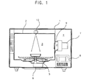
- a known microwave oven is shown in Figures 1 and 2.
- a microwave oven comprises a case 1 which is internally divided into a cooking chamber 3 and an electrical component chamber 4 by walls 2.
- a rotatable tray 5 for supporting food during cooking is located at the bottom of the cooking chamber 3.
- the rotatable tray 5 is rotated by a driving motor 6 installed at the lower side of the cabinet 2.
- the electrical component chamber 4 houses a plurality of electric devices including a magnetron 7 and a high voltage transformer 8.
- Microwaves generated by the magnetron 7 are guided by a waveguide 9 into the cooking chamber 3.
- the waveguide 9 opens into the cooking chamber 3.
- a door (not shown) is provided for providing access to the cooking chamber 3 and a controlling section for controlling the microwave oven are installed at the front of the case 1.
- An infrared sensor assembly 10 is installed centrally at the top of the cooking chamber 3 and is used to detect the temperature of food during cooking.
- the infrared sensor assembly 10 includes an infrared sensor 11, a printed circuit board 12, on which are mounted a plurality of electronic components (not shown) for producing an electrical signal in dependence on the food temperature sensed by the sensor 11, a cylindrical sensor cover 13, and a casing 14 housing the foregoing elements.
- the sensor cover 13 encases the infrared sensor 11 and has a hole 13a in its lower end.
- the sensor cover 13 projects toward the middle of the cooking chamber 3 through a hole defined in the upper wall 2 of the cooking chamber 3.
- the infrared sensor assembly 10 is positioned centrally at the top of the cooking chamber 3. This means that the field of view of the infrared sensor 11 is limited to the central portion of the rotatable tray 5. Accordingly, if the food to be cooked is placed outside of this limited field of view, the temperature of the food can not be precisely sensed. Also, although the infrared sensor 11 is covered by the sensor cover 13, the infrared sensor 11 is exposed to the humid atmosphere in the cooking chamber 13a through the hole 13a. Accordingly, the operation of the infrared sensor 11 becomes unstable and its temperature measurements unreliable.
- a microwave oven according to a first aspect of the present invention is characterised in that the sensor is directed obliquely towards a food receiving region of the cooking chamber from a position substantially at the top of the cooking chamber.
- the senor is located substantially at the front of the cooking chamber and is directed downward and rearwards. Preferably, the sensor is centrally located substantially at the from the cooking chamber.
- the senor is located outside the cooking chamber and senses food temperature via a hole in a wall of the cooking chamber.
- the hole is dimensioned such that the sensor has a field of view in the range 4° to 6°. More preferably, the hole is circular and has a diameter in the range 14mm to 25mm.
- a microwave oven according to a second aspect of the present invention is characterised by a shutter for protecting the sensor.
- the shutter comprises a substantially planar base having an aperture aligned with the sensor, first and second slidable plates lying plane parallel to the base and having respective apertures therein and drive means for sliding the first and second slidable plates in opposite directions between a closed configuration in which the slidable plates block each others apertures and the aperture of the base, and an open configuration in which all of the apertures are aligned with the sensor.
- the two aspects of the present invention will be combined in a single microwave oven.
- a microwave oven comprises a case 50 which is internally divided into a cooking chamber 54 and an electrical component chamber 56 by internal walls 52.
- a rotatable tray 58 is installed at bottom of the cooking chamber 54.
- the rotatable tray 58 is rotated by a driving motor 60 installed below the rotatable tray 58.
- the electrical component chamber 56 houses a plurality of electrical devices induding a magnetron 62, a waveguide 64 and a high voltage transformer.
- an infrared sensor assembly 100 for detecting the temperature of food during cooking comprises an infrared sensor 110, a printed circuit board 120, a sensor cover 130, a sensor protecting shutter 150 and a casing 140.
- the printed circuit board 120 supports a plurality of electronic components (not shown) for converting the sensed temperature of the food into an electrical signal and transmitting the signal to a control section.
- the sensor cover 130 is mounted to the printed circuit board 120 so as to encase the infrared sensor 110 and has a first hole 131 at its lower end.
- the sensor-protecting shutter 150 selectively opens and closes the first hole in the sensor cover 130.
- the casing 140 has a second hole 141 aligned with the first hole 131 of the sensor cover 130.
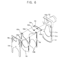
- the sensor-protecting shutter 150 comprises a base 151, first and second shutter plates 154, 155, an lever 153, a driving motor 152 and a shutter cover 156.
- the base 151 has a third hole 151a aligned with the first hole 131.
- the first and second shutter plates 154, 155 overlap each other in front of the base 151.
- the lever 153 reciprocally moves the first and the second shutter plates 154, 155 in opposite directions.
- the driving motor 152 drives the lever 153.
- the driving motor 152 is installed behind the upper part of the base 151 and has a rotary shaft 152a which passes through the base 151 and projects from the front surface of the base 151.
- the lever 153 is mounted to the rotary shaft 152a.
- the lever 153 is elastically supported by a torsion spring 153b which tends to rotate it clockwise as viewed in Figure 6.
- the first and second shutter plates 154, 155 have slits 154a, 155a and guide holes 154b, 155b.
- Support shafts 153a projecting from respective ends of the lever 153 are inserted into the slits 154a, 155a, and guide protrusions 151b formed on either side of the base 151 are inserted into the guide holes 154b, 155b.
- the first and second shutter plates 154, 155 are attached with to shutter cover 156 at the front of the assembly.
- the shutter cover 156 has arc-shape holes into which the free ends of the support shafts 153a are inserted.
- the infrared sensor assembly 100 is installed centrally in a front, upper portion of the cabinet 52.
- An observation hole 53 is formed in a wall 52 of the cooking chamber 54 in alignment with the second hole 141 of the casing 140.
- the infrared sensor assembly 100 is obliquely installed such that an extension of the centerline of the infrared sensor 110 and the observation hole 53 will pass through the middle of the rotatable tray 58.
- the observation hole 53 has such a diameter that the infrared sensor 110 has a field of view (a) of 4° ⁇ 6°, and more preferably 5°.
- the diameter of the observation hole 53 ranges from 14mm to 25mm.
- the infrared sensor 110 detects the temperature of the food positioned within the above field of view through the observation hole 53 during cooking. Even when the food is not centrally on the rotatable tray 58, its temperature can be accurately determined.
- the sensor-protecting shutter 150 opens the first hole 131 of the sensor cover 130 only when it is required to detect the temperature of the food.
- the sensor-protecting shutter 150 does not operate without power from the driving motor 152. Accordingly, the first and second shutter plates 154, 155 co-operate with each other so as to close the third hole 151a of the base 151.
- the driving motor 152 When electric power is applied to the driving motor 152, the rotary shaft 152a of the driving motor 152 rotates, rotating the lever 153 anticlockwise. Consequently, the first and second shutter plates 154 and 155 are moved by the support shafts 153a of the lever 153 in opposite directions.
- the first and second shutter plates 154, 155 move longitudinally along the base 151, guided by the guide protrusions 151b.
- the third hole 151a is opened and, accordingly, the first hole 131 of the sensor cover 130 is opened. Consequently, the infrared sensor 110 detects the temperature of the food in the cooking chamber 54 through the third hole 151a of the base 151 and the observation hole 53.
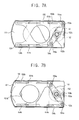
- Figure 7B shows the third hole 151a in its open state.
- the lever 153 When the electric power is cut-off, the lever 153 is rotated clockwise by the restoring force of the torsion spring 153b which was tensioned by the rotation of the lever 153. By the rotation of the lever 153, the first and second shutter plates 154, 155 move in opposite directions so as to close the third hole 151a of the base 151, as shown in Figure 7A. Accordingly, the first hole 131 of the sensor cover 130 is closed.
- the sensor-protecting shutter 150 opens the first hole 131 of the sensor cover 130 only when the infrared sensor 110 needs to detect the temperature of food, the negative factors of the cooking chamber such as humidity, microwaves etc. affect the infrared sensor 110 less.
- a microwave oven embodying all aspects of the present invention has the advantages of accurate temperature detection even when food not centrally placed on the rotating tray and protection of the sensor by means of the shutter. It should be noted that the aspects of the present invention need not both be embodied in a microwave oven.
Landscapes
- Physics & Mathematics (AREA)
- Electromagnetism (AREA)
- Electric Ovens (AREA)
- Radiation Pyrometers (AREA)
Abstract
Description
Claims (14)
- A microwave oven including a cooking chamber (54) and an infrared sensor (110) for sensing the temperature of food during cooking, characterised in that the sensor (110) is directed obliquely towards a food receiving region of the cooking chamber (54) from a position substantially at the top of the cooking chamber (54).
- A microwave oven according to claim 1, wherein the sensor (110) is located substantially at the front of the cooking chamber (54) and is directed downward and rearwards.
- A microwave oven according to claim 2, whereing the sensor (110) is centrally located substantially at the from the cooking chamber (54).
- A microwave oven according to claim 1, 2 or 3, wherein the sensor (110) is located outside the cooking chamber (54) and senses food temperature via a hole (53) in a wall (52) of the cooking chamber (54).
- A microwave oven according to to claim 4, wherein the hole (53) is dimensioned such that the sensor has a field of view (a) in the range 4° to 6°.
- A microwave oven according to claim 5, wherein the hole (53) is circular and has a diameter in the range 14mm to 25mm.
- A microwave oven induding a cooking chamber (54) and an infrared sensor (110) for sensing the temperature of food during cooking, characterised by a shutter (150)for protecting the sensor (110).
- A microwave oven according to claim 7, wherein the shutter (150) comprises a substantially planar base (151) having an aperture (151a) aligned with the sensor (110), first and second slidable plates (154, 155) lying plane parallel to the base (151) and having respective apertures therein and drive means (152, 152a, 153) for sliding the first and second slidable plates (154, 155) in opposite directions between a dosed configuration in which the slidable plates (154, 155) block each others apertures and the aperture (151a) of the base, and an open configuration in which all of the apertures are aligned with the sensor (110).
- A microwave oven according to any one of claims 1 to 6 and any one of claims 7 to 8.
- A microwave oven comprising:a case whose interior space is divided by a cabinet into a cooking chamber for receiving a food to be cooked and a device chamber for generating and supplying a microwave to the cooking chamber; andan infrared sensor assembly for detecting temperature of the food cooked by the microwave in the cooking chamber; the infrared sensor assembly being installed at a upper portion of the cabinet so as to face toward a central portion of a rotating dish from a front and upper middle portion of the cooking chamber;wherein the cabinet is defined with an observation hole corresponding to the infrared sensor assembly so as to interconnect the infrared sensor assembly with the cooking chamber.
- The microwave oven as claimed in claim 10, wherein the observation hole has a diameter that an infrared ray radiated from the food is detected by the infrared sensor assembly within a range from four to six degrees.
- The microwave oven as claimed in claim 11, wherein the diameter of the observation hole is in a range from fourteen millimeter to twenty five millimeter.
- The microwave oven as claimed in claim 11, wherein the infrared sensor assembly comprises:an infrared sensor for detecting the temperature of the food;a printed circuit board installed with a plurality of electric elements for converting the temperature of the food into an electric signal;a sensor cover encasing the infrared sensor, and having a first hole through which the infrared sensor detects the infrared ray of the food in the cooking chamber; a sensor protecting shutter for opening/closing the first hole of the sensor cover; anda casing for receiving the printed circuit board, the sensor cover, and the sensor protecting shutter, and having a second hole corresponding to the observation hole of the cabinet.
- The microwave oven as claimed in claim 13, wherein the sensor protecting shutter for infrared sensor comprises:a base having a third hole corresponding to the first hole of the sensor cover;an arm lever rotatably installed at a front and upper side of the base;a driving motor for rotating the arm lever;a first shutter plate moved in a longitudinal direction of the base by the arm lever;a second shutter plate, moved by the arm lever toward an opposite direction of the first shutter plate, for dosing/opening the third hole by incorporated with the first shutter plate; anda shutter cover, fixed to the base and formed with an opening corresponding to the third hole, for covering the arm lever, the first shutter plate, and the second shutter.
Applications Claiming Priority (2)
| Application Number | Priority Date | Filing Date | Title |
|---|---|---|---|
| KR9771944 | 1997-12-22 | ||
| KR19970071944 | 1997-12-22 |
Publications (2)
| Publication Number | Publication Date |
|---|---|
| EP0924964A2 true EP0924964A2 (en) | 1999-06-23 |
| EP0924964A3 EP0924964A3 (en) | 2000-04-12 |
Family
ID=19528170
Family Applications (1)
| Application Number | Title | Priority Date | Filing Date |
|---|---|---|---|
| EP98309204A Withdrawn EP0924964A3 (en) | 1997-12-22 | 1998-11-10 | Microwave oven with infrared sensor |
Country Status (4)
| Country | Link |
|---|---|
| EP (1) | EP0924964A3 (en) |
| JP (1) | JPH11193930A (en) |
| KR (1) | KR19990062452A (en) |
| CN (1) | CN1221093A (en) |
Cited By (4)
| Publication number | Priority date | Publication date | Assignee | Title |
|---|---|---|---|---|
| WO2011080223A3 (en) * | 2009-12-31 | 2011-10-06 | Arcelik Anonim Sirketi | A cooking device |
| CN107397444A (en) * | 2016-05-18 | 2017-11-28 | 佛山市顺德区美的电热电器制造有限公司 | Pot lid and cooking pot tool |
| WO2020229452A1 (en) | 2019-05-13 | 2020-11-19 | BSH Hausgeräte GmbH | Cooking appliance having sensor units arranged outside the cooking chamber |
| DE102021200669A1 (en) | 2021-01-26 | 2022-07-28 | BSH Hausgeräte GmbH | Household cooking appliance with a motorized sensor that can be moved lengthwise |
Families Citing this family (11)
| Publication number | Priority date | Publication date | Assignee | Title |
|---|---|---|---|---|
| JP2009168462A (en) * | 2008-01-10 | 2009-07-30 | Toyota Central R&D Labs Inc | Temperature distribution measuring device for microwave heating and temperature distribution measuring method for microwave heating |
| JP2009236888A (en) * | 2008-03-28 | 2009-10-15 | Toyota Central R&D Labs Inc | Temperature distribution measuring device for microwave heating and temperature distribution measurement method for microwave heating |
| CN102028414B (en) * | 2009-09-28 | 2014-07-30 | 深圳市繁兴科技有限公司 | Space isolation device and cooking equipment applying same |
| US10079982B2 (en) | 2011-06-10 | 2018-09-18 | Flir Systems, Inc. | Determination of an absolute radiometric value using blocked infrared sensors |
| CN103907342B (en) * | 2011-10-07 | 2018-10-23 | 菲力尔系统公司 | The method and apparatus for determining absolute radiation value using barrier infrared sensor |
| CN108731036B (en) * | 2017-04-20 | 2019-09-03 | 珠海格力电器股份有限公司 | Electric appliance for kitchen |
| CN108826380A (en) * | 2018-05-09 | 2018-11-16 | 海尔优家智能科技(北京)有限公司 | A kind of micro-wave oven temperature measuring equipment, method and micro-wave oven |
| CN111102615A (en) * | 2018-10-26 | 2020-05-05 | 博西华电器(江苏)有限公司 | Control method for range hood and range hood control system |
| DE102019213485A1 (en) * | 2019-09-05 | 2021-03-11 | BSH Hausgeräte GmbH | Household microwave oven with microwave dome |
| CN112874499A (en) * | 2021-01-15 | 2021-06-01 | 合肥青冠机电科技有限公司 | Brake monitoring system |
| CN114167758B (en) * | 2021-11-22 | 2024-02-23 | 珠海格力电器股份有限公司 | Cooking apparatus, cooking apparatus control method, and storage medium |
Family Cites Families (8)
| Publication number | Priority date | Publication date | Assignee | Title |
|---|---|---|---|---|
| JPS5261848A (en) * | 1975-11-17 | 1977-05-21 | Matsushita Electric Ind Co Ltd | High frequency heater |
| JPS5813816B2 (en) * | 1977-07-15 | 1983-03-16 | 松下電器産業株式会社 | High frequency heating device |
| JPS5759850Y2 (en) * | 1978-07-13 | 1982-12-21 | ||
| DE3069395D1 (en) * | 1979-03-02 | 1984-11-15 | Matsushita Electric Industrial Co Ltd | Heat-cooking apparatus incorporating infrared detecting system |
| US4360723A (en) * | 1979-10-31 | 1982-11-23 | Tokyo Shibaura Denki Kabushiki Kaisha | Microwave oven |
| JPS58220385A (en) * | 1982-06-16 | 1983-12-21 | 三洋電機株式会社 | Electronic control type cooking device |
| US5693248A (en) * | 1995-07-07 | 1997-12-02 | Lg Electronics Inc. | Sensor malfunction prevention apparatus for microwave oven |
| SE505555C2 (en) * | 1995-12-21 | 1997-09-15 | Whirlpool Europ | Method for controlling a heating process in a microwave oven and microwave oven |
-
1998
- 1998-07-14 KR KR1019980028338A patent/KR19990062452A/en not_active Ceased
- 1998-08-20 CN CN98118485A patent/CN1221093A/en active Pending
- 1998-09-03 JP JP10250183A patent/JPH11193930A/en active Pending
- 1998-11-10 EP EP98309204A patent/EP0924964A3/en not_active Withdrawn
Cited By (8)
| Publication number | Priority date | Publication date | Assignee | Title |
|---|---|---|---|---|
| WO2011080223A3 (en) * | 2009-12-31 | 2011-10-06 | Arcelik Anonim Sirketi | A cooking device |
| CN107397444A (en) * | 2016-05-18 | 2017-11-28 | 佛山市顺德区美的电热电器制造有限公司 | Pot lid and cooking pot tool |
| CN107397444B (en) * | 2016-05-18 | 2023-09-01 | 佛山市顺德区美的电热电器制造有限公司 | Pot cover and cooking pot |
| WO2020229452A1 (en) | 2019-05-13 | 2020-11-19 | BSH Hausgeräte GmbH | Cooking appliance having sensor units arranged outside the cooking chamber |
| US12207377B2 (en) | 2019-05-13 | 2025-01-21 | BSH Hausgeräte GmbH | Cooking appliance having sensor units arranged outside the cooking chamber |
| DE102021200669A1 (en) | 2021-01-26 | 2022-07-28 | BSH Hausgeräte GmbH | Household cooking appliance with a motorized sensor that can be moved lengthwise |
| WO2022161777A1 (en) | 2021-01-26 | 2022-08-04 | BSH Hausgeräte GmbH | Domestic cooking appliance having a sensor that is longitudinally movable by motor power |
| EP4380313A2 (en) | 2021-01-26 | 2024-06-05 | BSH Hausgeräte GmbH | Domestic cooking appliance having a sensor that is longitudinally movable by motor power |
Also Published As
| Publication number | Publication date |
|---|---|
| CN1221093A (en) | 1999-06-30 |
| KR19990062452A (en) | 1999-07-26 |
| JPH11193930A (en) | 1999-07-21 |
| EP0924964A3 (en) | 2000-04-12 |
Similar Documents
| Publication | Publication Date | Title |
|---|---|---|
| JPH11193930A (en) | microwave | |
| KR101887054B1 (en) | Infrared ray detecting device and heating cooker including the same | |
| EP3435736B1 (en) | Microwave heating apparatus | |
| EP2451246B1 (en) | Heating cooker with an infrared ray detection device and method of measuring the temperature of a cooking chamber of the heating cooker | |
| US4747712A (en) | Device for rotating and supporting a temperature probe | |
| US20120111204A1 (en) | Heating cooker | |
| CN1283955C (en) | Cooking device equipped with a weight measuring unit | |
| JP2001227748A (en) | microwave | |
| US6051824A (en) | Wet prevention apparatus for sensor of microwave oven | |
| US12256481B2 (en) | Household microwave appliance having mode variation apparatus | |
| CA1228648A (en) | Device for rotating and supporting a temperature probe | |
| JP2007024829A (en) | Temperature detector and high frequency heater | |
| KR20000051360A (en) | Microwave oven | |
| KR880001087B1 (en) | Microwave oven | |
| KR20100063197A (en) | Door opening/closing device and cooker comprising the same | |
| EP1283661B1 (en) | Humidity sensor and microwave oven including a humidity sensor | |
| KR100233441B1 (en) | Apparatus for protecting the temperature sensor of a microwave oven | |
| JP7718178B2 (en) | Electronic balance | |
| JP4262519B2 (en) | Cooker | |
| CA1201487A (en) | Microwave oven with outwardly inclining control panel | |
| KR960004386Y1 (en) | Microwave Weight Sensor | |
| JPH05118554A (en) | Cooker weight sensor | |
| KR20000026433A (en) | Device for sensing weight for microwave oven | |
| JPH07113682A (en) | Heating cooker | |
| KR100277963B1 (en) | Microwave Weight Sensor Assembly |
Legal Events
| Date | Code | Title | Description |
|---|---|---|---|
| PUAI | Public reference made under article 153(3) epc to a published international application that has entered the european phase |
Free format text: ORIGINAL CODE: 0009012 |
|
| AK | Designated contracting states |
Kind code of ref document: A2 Designated state(s): AT BE CH CY DE DK ES FI FR GB GR IE IT LI LU MC NL PT SE |
|
| AX | Request for extension of the european patent |
Free format text: AL;LT;LV;MK;RO;SI |
|
| PUAL | Search report despatched |
Free format text: ORIGINAL CODE: 0009013 |
|
| AK | Designated contracting states |
Kind code of ref document: A3 Designated state(s): AT BE CH CY DE DK ES FI FR GB GR IE IT LI LU MC NL PT SE |
|
| AX | Request for extension of the european patent |
Free format text: AL;LT;LV;MK;RO;SI |
|
| AKX | Designation fees paid | ||
| REG | Reference to a national code |
Ref country code: DE Ref legal event code: 8566 |
|
| STAA | Information on the status of an ep patent application or granted ep patent |
Free format text: STATUS: THE APPLICATION IS DEEMED TO BE WITHDRAWN |
|
| 18D | Application deemed to be withdrawn |
Effective date: 20001013 |