EP3968485A1 - Appareil électronique et procédé - Google Patents
Appareil électronique et procédé Download PDFInfo
- Publication number
- EP3968485A1 EP3968485A1 EP21158933.8A EP21158933A EP3968485A1 EP 3968485 A1 EP3968485 A1 EP 3968485A1 EP 21158933 A EP21158933 A EP 21158933A EP 3968485 A1 EP3968485 A1 EP 3968485A1
- Authority
- EP
- European Patent Office
- Prior art keywords
- power
- power system
- islanding
- electronic apparatus
- partial
- Prior art date
- Legal status (The legal status is an assumption and is not a legal conclusion. Google has not performed a legal analysis and makes no representation as to the accuracy of the status listed.)
- Pending
Links
Images


Classifications
-
- H—ELECTRICITY
- H02—GENERATION; CONVERSION OR DISTRIBUTION OF ELECTRIC POWER
- H02J—CIRCUIT ARRANGEMENTS OR SYSTEMS FOR SUPPLYING OR DISTRIBUTING ELECTRIC POWER; SYSTEMS FOR STORING ELECTRIC ENERGY
- H02J3/00—Circuit arrangements for ac mains or ac distribution networks
- H02J3/001—Methods to deal with contingencies, e.g. abnormalities, faults or failures
- H02J3/0012—Contingency detection
-
- H—ELECTRICITY
- H02—GENERATION; CONVERSION OR DISTRIBUTION OF ELECTRIC POWER
- H02H—EMERGENCY PROTECTIVE CIRCUIT ARRANGEMENTS
- H02H7/00—Emergency protective circuit arrangements specially adapted for specific types of electric machines or apparatus or for sectionalised protection of cable or line systems, and effecting automatic switching in the event of an undesired change from normal working conditions
- H02H7/26—Sectionalised protection of cable or line systems, e.g. for disconnecting a section on which a short-circuit, earth fault, or arc discharge has occured
-
- H—ELECTRICITY
- H02—GENERATION; CONVERSION OR DISTRIBUTION OF ELECTRIC POWER
- H02J—CIRCUIT ARRANGEMENTS OR SYSTEMS FOR SUPPLYING OR DISTRIBUTING ELECTRIC POWER; SYSTEMS FOR STORING ELECTRIC ENERGY
- H02J3/00—Circuit arrangements for ac mains or ac distribution networks
- H02J3/38—Arrangements for parallely feeding a single network by two or more generators, converters or transformers
- H02J3/388—Islanding, i.e. disconnection of local power supply from the network
-
- H—ELECTRICITY
- H02—GENERATION; CONVERSION OR DISTRIBUTION OF ELECTRIC POWER
- H02J—CIRCUIT ARRANGEMENTS OR SYSTEMS FOR SUPPLYING OR DISTRIBUTING ELECTRIC POWER; SYSTEMS FOR STORING ELECTRIC ENERGY
- H02J3/00—Circuit arrangements for ac mains or ac distribution networks
- H02J3/38—Arrangements for parallely feeding a single network by two or more generators, converters or transformers
- H02J3/46—Controlling of the sharing of output between the generators, converters, or transformers
-
- H—ELECTRICITY
- H02—GENERATION; CONVERSION OR DISTRIBUTION OF ELECTRIC POWER
- H02J—CIRCUIT ARRANGEMENTS OR SYSTEMS FOR SUPPLYING OR DISTRIBUTING ELECTRIC POWER; SYSTEMS FOR STORING ELECTRIC ENERGY
- H02J2300/00—Systems for supplying or distributing electric power characterised by decentralized, dispersed, or local generation
- H02J2300/20—The dispersed energy generation being of renewable origin
- H02J2300/22—The renewable source being solar energy
- H02J2300/24—The renewable source being solar energy of photovoltaic origin
-
- H—ELECTRICITY
- H02—GENERATION; CONVERSION OR DISTRIBUTION OF ELECTRIC POWER
- H02J—CIRCUIT ARRANGEMENTS OR SYSTEMS FOR SUPPLYING OR DISTRIBUTING ELECTRIC POWER; SYSTEMS FOR STORING ELECTRIC ENERGY
- H02J2300/00—Systems for supplying or distributing electric power characterised by decentralized, dispersed, or local generation
- H02J2300/20—The dispersed energy generation being of renewable origin
- H02J2300/28—The renewable source being wind energy
-
- Y—GENERAL TAGGING OF NEW TECHNOLOGICAL DEVELOPMENTS; GENERAL TAGGING OF CROSS-SECTIONAL TECHNOLOGIES SPANNING OVER SEVERAL SECTIONS OF THE IPC; TECHNICAL SUBJECTS COVERED BY FORMER USPC CROSS-REFERENCE ART COLLECTIONS [XRACs] AND DIGESTS
- Y02—TECHNOLOGIES OR APPLICATIONS FOR MITIGATION OR ADAPTATION AGAINST CLIMATE CHANGE
- Y02E—REDUCTION OF GREENHOUSE GAS [GHG] EMISSIONS, RELATED TO ENERGY GENERATION, TRANSMISSION OR DISTRIBUTION
- Y02E10/00—Energy generation through renewable energy sources
- Y02E10/50—Photovoltaic [PV] energy
- Y02E10/56—Power conversion systems, e.g. maximum power point trackers
Definitions
- frequency feedback scheme with step injection As one of islanding detection schemes, there is an active scheme called "frequency feedback scheme with step injection.” This scheme detects islanding of a power source device by abruptly injecting reactive power so as to further promote a frequency change of a power system from a frequency change rate of the power system and examining the frequency change.
- each power source device is desired to operate independently (islanding) while the device remains disconnected from the power system in the microgrid.
- operation of each power source device cannot be started due to an islanding detection function of the power source device. For this reason, it is not possible to supply power in the microgrid.
- an electronic apparatus connectable to a partial power system which is a part of a power system and comprises a first power source apparatus, power supply of the first power source apparatus stopped in response to detecting an islanding of the partial power system includes: controlling circuitry configured to output to the partial power system a first signal to disable detecting the islanding of the partial power system by the first power source apparatus during at least part of a period during which the partial power system is electrically separated from the power system.
- FIG. 1 is a diagram illustrating an overall configuration of a power system according to the present approach.
- Power source devices power source apparatuses
- 31A, 31B, 32A and 32B, a demander device 3 and a synchronous power generation device 4 are connected to a power system 1 via a circuit breaker 2.
- the power source devices 31A, 31B, 32A and 32B are provided with PCSs (power conditioning systems) 11A, 11B, 12A and 12B, which are power conversion devices, and power supply devices 21A, 21B, 22A and 22B, which are connected to the PCSs.
- PCSs power conditioning systems
- the power supply device 21A is a photovoltaic power generation device
- the power supply device 21B is a power storage device, which is a chargeable/dischargeable secondary battery
- the power supply device 22A is a wind power generation device
- the power supply device 22B is a photovoltaic power generation device.
- a partial power system of the power system 1 to which the power source devices 31A, 31B, 32A and 32B, the demander device 3 and the synchronous power generation device 4 are connected is a microgrid 1M.
- the microgrid 1M is a part of the power system 1.
- the PCSs 11A, 11B, 12A and 12B are each an electronic apparatus configured to generate power to be used by the demander device 3 by converting power supplied from the photovoltaic power generation device 21A, the power storage device 21B, the wind power generation device 22A, and the photovoltaic power generation device 22B to AC respectively.
- the PCSs are also called inverters (power conversion devices).
- the PCSs 11A and 11B are PCSs according to the present approach (electronic apparatuses according to the present approach) and the PCSs 12A and 12B are general PCSs (existing PCSs).
- the demander device 3 is a load device that consumes power in a household, school, factory, business operator or the like or a power storage device that stores surplus power in the power system 1. Although only one demander device 3 is illustrated in FIG. 1 , there can be a plurality of demander devices 3.
- the circuit breaker 2 In the event of an abnormality such as an accident occurring in the power system 1, or in case of emergency during work or emergency such as fire, the circuit breaker 2 is opened. In the event of a power outage or when the circuit breaker 2 is opened, the microgrid 1M is electrically separated (disconnected) from the power system 1 and in a state of no power supply. At this time, the microgrid 1M functions as a distributed power supply system configured to be operable independently using renewable energy from the power generation device and the power storage device.
- the synchronous power generation device 4 is an AC power generator configured to generate AC power and provide the AC power to the power system 1 or the microgrid 1M.
- the synchronous power generation device 4 includes an emergency power generator, a normal power generator or both.
- the emergency power generator is, for example, an emergency diesel power generator.
- the emergency diesel power generator is not operated at a normal time, and when an abnormality or the like occurs in the power system 1, and the emergency diesel power generator is disconnected from the power system 1, the emergency diesel power generator starts operating under an instruction from an operator.
- the instruction from the operator may be given by a switch such as a button provided in the synchronous power generation device 4.
- the instruction from the operator may be given by transmitting a command signal wirelessly or by wire from a terminal available to the operator or from a terminal available to the supervisor of the control center.
- the terminal operable by the operator is, for example, a maintenance tablet terminal.
- the terminal operable by the supervisor is, for example, a server or the like that supervises the microgrid 1M on line or off line.
- a configuration not provided with any synchronous power generation device 4 is also possible.
- a governor of the power generator may be used by switching between one with an isochronous characteristic and the other with a droop characteristic.
- the governor with the isochronous characteristic performs control such that the rotational speed of the power generator becomes constant regardless of the magnitude of a load connected.
- the governor with the droop characteristic performs control such that the rotational speed of the power generator varies depending on the magnitude of the load connected to share the load with the other synchronous power generators for load fluctuation or the like.
- the governor may be switched to the one with the droop characteristic at a normal time when the system works in tandem, and the governor may be switched to the other with the isochronous characteristic when used off-grid in case of an emergency or the like.
- the circuit breaker 2 is closed.
- the circuit breaker 2 When the circuit breaker 2 is closed, power is supplied from the photovoltaic power generation device 21A, the power storage device 21B, the wind power generation device 22A and the photovoltaic power generation device 22B to the power system 1 via the PCSs 11A, 11B, 12A and 12B connected respectively.
- the supplied power is supplied to the demander device 3.
- Power supplied from at least one of the photovoltaic power generation device 21A, the wind power generation device 22A and the photovoltaic power generation device 22B may be supplied to the power storage device 21B and stored.
- the circuit breaker 2 When an abnormality such as an accident occurs in the power system 1, or the like, the circuit breaker 2 is opened and the PCSs 11A, 11B, 12A and 12B or the like are connected to the microgrid 1M disconnected from the power system 1.
- the PCSs 11A, 11B, 12A and 12B are each provided with a mechanism for detecting whether or not each own device is performing islanding.
- the islanding refers to each PCS (or power source device) operating without being disconnected from the power system 1 with no power supply from the power system 1.
- the PCSs 11A, 11B, 12A and 12B are provided with a function of inspecting at all times whether or not the own device is performing islanding and disconnecting the own device from the power system 1 when islanding is detected.
- a process of detecting whether or not islanding is being performed is called an "islanding detection process.”
- the active scheme is a scheme that gives a fluctuation at all times to a voltage or frequency using a resistor or the like added to a PCS control system or PCS exterior, and detects a fluctuation which becomes significant at the time of transition to islanding.
- the active scheme includes a conventional active scheme and a new active scheme. Examples of the conventional active scheme include a frequency shift scheme, a slip mode frequency shift scheme, an active power fluctuation scheme, reactive power fluctuation scheme, and a load fluctuation scheme.
- the new active scheme is a scheme obtained by increasing a detection speed of the islanding detection function of the conventional active scheme, and a frequency feedback scheme with step injection or the like is known.
- the frequency feedback scheme with step injection is a scheme for detecting PCS islanding by abruptly injecting reactive power (islanding detection signal) so as to further promote a frequency change of the power system 1 from a frequency change rate of the power system 1 and examining the frequency change.
- the islanding detection signal corresponds to a second signal for each PCS to promote a frequency change or a voltage change in the power system 1.
- the PCSs 11A and 11B are PCSs according to the present approach, and the PCSs 12A and 12B are existing PCSs.
- the islanding detection functions of the PCSs 12A and 12B are always in on state, whereas the islanding detection functions of the PCSs 11A and 11B are configured to be switchable between on and off states.
- the islanding detection functions of the PCSs 11A and 11B are set in on-state during normal operation when the circuit breaker 2 is closed.
- the PCSs 11A and 11B are provided with a function of disabling the islanding detection functions of the PCSs 12A and 12B (existing-PCS-islanding disabling functions).
- the existing-PCS-islanding disabling function is a function (first function) of outputting a signal for canceling at least part of a change in frequency or voltage in the microgrid 1M for reactive power (islanding detection signal) outputted by the PCSs 12A and 12B for islanding detection.
- the existing-PCS-islanding disabling functions of the PCSs 11A and 11B are set to "disabled," and no process of disabling the islanding detection functions of the PCSs 12A and 12B is performed.
- the PCSs 11A, 11B, 12A and 12B detect islandings of the respective own devices using the islanding detection functions, the PCSs disconnect the own devices from the power system 1 and stop the respective operations. That is, AC power supply to the power system 1 or the microgrid 1M is stopped.
- FIG. 2 illustrates an example where the PCSs 11A, 11B, 12A and 12B output reactive power (islanding detection signals) to the microgrid 1M.
- the PCSs 11A, 11B, 12A and 12B detect islanding of the own devices according to output of reactive power, which are islanding detection signals.
- the PCSs 11A, 11B, 12A and 12B from which islanding have been detected disconnect the own devices from the microgrid 1M. This causes the power in the microgrid 1M to go out. After that, for example, the circuit breaker 2 is opened and the microgrid 1M is disconnected from the power system 1.
- FIG. 3 illustrates an operation example of each PCS and the synchronous power generation device 4 when power supply is started in the microgrid 1M disconnected from the power system 1.
- the synchronous power generation device 4 here, the emergency power generator
- the PCSs 11A, 11B, 12A and 12B receive an instruction for restarting operation from the operator and restart the operation.
- the instruction from the operator may be given using a switch such as a button provided on each PCS.
- the instruction from the operator may also be given by transmitting a command signal wirelessly or by wire to the respective PCSs from a terminal available to the operator, or from a terminal available to the supervisor of the control center.
- the islanding detection functions of the own devices are set to "off" according to an instruction from the operator, and the existing-PCS-islanding disabling functions are set to "enabled.”
- the PCSs 12A and 12B supply power to the microgrid 1M in the same way as before the disconnection, whereas the PCSs 12A and 12B output the islanding detection signals (reactive power) to the microgrid 1M.
- the existing-PCS-islanding disabling functions provided for the PCSs 11A and 11B according to the present approach are enabled. This causes a disabling signal (reactive power or active power or reactive power and active power) that at least partially cancels a frequency change promoted by islanding detection signals (reactive power) outputted to the microgrid 1M by the PCSs 12A and 12B to be outputted from the PCSs 11A and 11B to the microgrid 1M.
- the canceling signal corresponds to a first signal for disabling an islanding detection process by the PCSs 12A and 12B.
- An example of the disabling signal is reactive power or active power. This causes the PCSs 12A and 12B not to detect a frequency change necessary to detect islanding in the microgrid 1M and not to detect islanding of the own devices. This disables the islanding detection process in the PCSs 12A and 12B. Thus, the PCSs 12A and 12B are not disconnected from the microgrid 1M and can supply power. Since the present approach uses the frequency feedback scheme with step injection, a signal for canceling a frequency change is outputted, but it is only necessary to generate an appropriate signal according to the detection scheme used as appropriate. In the case of a scheme for detecting a voltage change, a signal for canceling a voltage change may be outputted as the disabling signal.
- the PCSs 11A and 11B output the above-described disabling signals while supplying power to the microgrid 1M. Since the islanding detection functions of the PCSs 11A and 11B are set to "off,” operation for detecting islanding of the own device is not performed and it is thereby possible to supply power to the microgrid 1M.
- the synchronous power generation device 4 (here, emergency power generator) is operated first and operations of the PCSs 11A, 11B, 12A and 12B are then restarted, but a configuration of not allowing the synchronous power generation device 4 to operate is also possible.
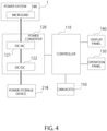
- FIG. 4 is a block diagram of the PCS 11A according to the present approach.
- FIG. 5 is a block diagram of the PCS 11B according to the present approach.
- the PCS 11A in FIG. 4 is provided with a controller 110 (controlling circuitry), a power converter 120 and a communicator 150.
- the controller 110 is connected to an operation panel 130 and a display panel 140.
- the power converter 120 is provided with a DC/AC 121 and a DC/DC 122.
- the controller 110, the power converter 120 and the communicator 150 are configured of an analog circuit, a digital circuit or both circuits. Part or all of the controller 110 and the power converter 120 may also be implemented by causing a processor such as a CPU or a microcomputer to execute a computer program stored in a memory.
- a DC/DC 122 of the power converter 120 performs a DC-DC conversion of a DC voltage of power supplied from the power storage device 21B.
- the DC/AC 121 converts the DC-DC converted power of DC voltage to AC power available to the demander device 3.
- the power converter 120 outputs the converted AC power to the microgrid 1M or the power system 1.
- the power converter 120 is configured to be able to output reactive power or active power or reactive power and active power as an islanding detection signal of the own device.
- the power converter 120 is configured to be able to output reactive power or active power or reactive power and active power as a disabling signal to disable an islanding detection function of the existing PCS.
- the communicator 150 communicates with a terminal operable by the operator or a terminal operable by the supervisor of the control center. Communication may be wireless communication such as wireless LAN, mobile network communication or Bluetooth, or wired communication such as Ethernet or serial communication. The communicator 150 may also communicate with at least one of the other PCSs 11B, 12A and 12B, the demander device 3 and the synchronous power generation device 4.
- the display panel 140 displays an enabled or disabled state of the existing-PCS-islanding detection function and displays an on or off state of the islanding detection function of the own device.
- the display panel 140 is provided, for example, in an external housing of the PCS 11A and can be visually checked by the operator.
- FIG. 6 illustrates an example of appearance of the PCS 11A.
- the display panel 140 is provided on the external housing of the PCS 11A. The operator pinches a handle 145 to open the door and can thereby enter inside the housing. Devices such as the power converter 120 are disposed in the housing.
- Light emitters 141 and 142 are provided on the display panel 140 outside the housing.
- the light emitter 141 emits light of a color representing an enabled or disabled state of the existing-PCS-islanding disabling function.
- the light emitter 142 emits light of a color representing an on or off state of the islanding detection function of the own device.
- the light emitter 141 includes multi-color light-emitting diodes (LEDs) or lamps and causes different LEDs to emit light according to an enabled or disabled state of the existing-PCS-islanding disabling function.
- the light emitter 141 includes multi-color light-emitting diodes and causes different LEDs to emit light according to an on or off state of the islanding detection function of the own device. This allows the operator to easily confirm a state of each function from outside the PCS housing.
- Display devices such as a liquid crystal display device or organic EL display device may be used instead of the light emitters 141 and 142.
- information indicating a state may be displayed using text or image or the like.
- the controller 110 is provided with an output device that outputs an enabled or disabled state of the existing-PCS-islanding disabling function or an on or off state of the islanding detection function to the display panel 140.
- An enabled or disabled state of the existing-PCS-islanding detection function or an on or off state of the islanding detection function may also be displayed on a terminal operable by the operator or a terminal operable by the supervisor of the control center.
- the controller 110 transmits information indicating an enabled or disabled state of the existing-PCS-islanding detection function or an on or off state of the islanding detection function to the terminal via the communicator 150.
- the terminal displays the received information on a screen.
- the communicator 150 is an example of an output device configured to output an enabled or disabled state of the existing-PCS-islanding detection function or an on or off state of the islanding function.
- the operation panel 130 is intended to perform operation of switching an enabled or disabled setting of the existing-PCS-islanding disabling function and operation of switching an on or off setting of the islanding detection function, or the like.
- FIG. 7 illustrates an example of appearance of the operation panel 130.
- the operation panel 130 is disposed, for example, in the housing of the PCS 11A (e.g., in the housing shown in FIG. 6 ). The operator can open the door of the housing to operate the operation panel 130.
- the operation panel 130 is provided with an existing-PCS-islanding disabling button 41, an islanding detection function off button 42 and a black start button 43.
- the existing-PCS-islanding disabling button 41 is a button configured to switch an enabled or disabled state of the existing-PCS-islanding disabling function.
- the islanding detection function off button 42 is a button configured to switch an on or off state of the islanding detection function of the own device.
- the black start button 43 is a button configured to restart operation of the PCS 11A disconnected from the power system 1.
- a command signal by each button on the operation panel 130 is transmitted to the controller 110.
- the controller 110 controls operation of the power converter 120 based on the command signal by each button.
- the controller 110 When the existing-PCS-islanding disabling function is enabled by the existing-PCS-islanding disabling button 41, the controller 110 performs a process of disabling the islanding detection function of the existing PCS. That is, when reactive power is inputted from the existing PCS 12A or 12B as an islanding detection signal, the controller 110 estimates the reactive power from a voltage and a frequency of the microgrid 1M. The controller 110 generates a disabling signal to cancel a frequency change (to prevent a frequency change) in the microgrid 1M by the inputted reactive power and outputs the generated disabling signal to the microgrid 1M. As an example of the disabling signal, the controller 110 generates reactive power or active power or reactive power and active power.
- the existing PCSs 12A and 12B not to further detect islanding, and can thereby disable the islanding detection functions of the existing PCSs 12A and 12B and cause the PCSs 12A and 12B to perform autonomous operation.
- the existing-PCS-islanding disabling function is disabled at normal times. The present function is enabled only when the existing PCS is made to perform autonomous operation at the time of off-grid such as in the event of a disaster.
- the controller 110 outputs a disabling signal (first signal) for disabling an islanding detection process by the existing PCS connected to the power system 1 to the microgrid 1M for at least part of the period during which the power system 1 is disconnected.
- the existing-PCS-islanding disabling button 41 is an example of the switch for switching an enabled or disabled state of the existing-PCS-islanding disabling function.
- a switchable configuration may also be implemented using a hard switch provided for the PCS, a switch displayed on a touch panel operable by each PCS, or a switch of a maintenance device.
- an enabled or disabled state of the existing-PCS-islanding disabling function may be switched by updating a program to be executed by the controller 110 using a maintenance terminal (personal computer or the like). That is, the program includes a code to set an enabled or disabled state of the function and the code is configured to be rewritable. The operator updates the code so as to be set in an enabled state when the operator wants to enable the function, writes the updated program from the terminal to the controller 110 and causes the controller 110 to execute the program.
- the controller 110 When the islanding detection function of the own device is "on,” the controller 110 outputs reactive power as an islanding detection signal according to the frequency feedback scheme with step injection and detects the presence or absence of the islanding. During normal operation, the islanding detection function is set to “on.” When the islanding detection function is set to "off” by the islanding detection function off button 42, for example, in the event of an abnormality occurring in the power system 1, the controller 110 does not output any islanding detection signal. This allows the PCSs 11A and 11B to perform autonomous operation at the time of off-grid and supply power to the microgrid 1M.
- the controller 110 Upon detecting islanding of the own device, the controller 110 disconnects the own device from the power system 1 and stops operation. This is an example of control by the controller 110 for stopping at least part of the microgrid 1M (partial power system).
- the controller 110 performs control for causing at least part of the microgrid 1M to perform islanding.
- the controller 110 causes the own device to restart operation.
- the controller 110 outputs a first signal (disabling signal) for disabling detection of islanding by another power source device to the microgrid 1M.
- the controller 110 controls the power converter 120 so as to generate AC power to be supplied to the demander device 3. That is, the controller 110 controls the power converter 120 to supply AC power to the power system 1 or the microgrid 1M regardless of the enabled or disabled state of the existing-PCS-islanding detection function or the on or off state of the islanding detection function.
- the controller 110 may include a storage to store various kinds of information or data.
- the storage stores information indicating an enabled or disabled state of the existing-PCS-islanding detection function or information indicating an on or off state of the islanding detection function, or the like.
- the storage also stores various kinds of parameter information necessary to control the power converter 120.
- the controller 110 executes a program, the program is stored in the storage.
- the storage includes at least one or more storage media such as a volatile memory, non-volatile memory, hard disk or SSD.
- FIG. 8 is a flowchart of a series of operations when power is supplied in the microgrid 1M at the time of off-grid in the event of an abnormality in the power system 1 in the present approach.
- a power outage occurs in the power system 1 (S11).
- the PCSs 11A, 11B, 12A and 12B detect islanding of the respective own devices and stop operation (S12). This causes the inside of the microgrid 1M to be placed in a state in which power is no longer supplied (power outage) (S13).
- Maintenance staff of the power system 1 opens the circuit breaker 2 of the power system 1 (S14). Note that the circuit breaker 2 may also be opened by automatic control according to the state of the power system 1.
- the operator turns on the islanding detection function off buttons 42 of the PCSs 11A and 11B (S16). That is, the islanding detection function is turned off.
- the operator enables the existing-PCS-islanding disabling functions of the PCSs 11A and 11B (S17). That is, the operator enables the function of disabling the islanding detection functions of the existing PCSs 12A and 12B (first function).
- the operator starts the emergency power generator included in the synchronous power generation device 4.
- the synchronous power generator used as a normal power generator may be switched by a governor switch from a mode having a droop characteristic to a mode having an isochronous characteristic and may be started as an emergency power generator.
- the PCS may be started with a droop characteristic (in a normal power generator mode) from the standpoint of load sharing (S18).
- the operator turns on the black start button 43 to restart the operations of the PCSs 11A and 11B (S19).
- the operator restarts the operations of the PCSs 12A and 12B (S20).
- FIG. 9 is a flowchart of a series of operations to connect the microgrid 1M to the power system 1 and restore the microgrid 1M to an on-grid state when the power system 1 of the present approach is restored from a power outage.
- the power system 1 is restored from the power outage (S21).
- the circuit breaker 2 is opened at this point in time.
- Autonomous operations of all the PCSs 11A, 11B, 12A and 12B in the microgrid 1M are stopped through operation by the operator (S22).
- Operation of the emergency power generator is stopped through operation by the operator (S23). This causes the power in the microgrid 1M to go out (S24).
- the operator When safety in the microgrid 1M is confirmed (S25), the operator operates the existing-PCS-islanding disabling button 41 to set the existing-PCS-islanding disabling functions of the PCSs 11A and 11B to a disabled state (S26).
- the operator operates the islanding detection function off button 42 to turn on the islanding detection functions of the PCSs 11A and 11B (S27).
- the maintenance staff of the power system 1 closes the circuit breaker 2 (S28).
- the normal power generator included in the synchronous power generation device 4 is started. When the emergency power generator is operated with an isochronous characteristic, the characteristic may be returned to a droop characteristic and the mode may be switched to a normal power generator mode (S29).
- the operations of the PCSs 11A, 11B, 12A and 12B is started through operation by the operator (S30).
- the operator may turn off the black start buttons 43 of the PCSs 11A and 12B.
- the normal power generator included in the synchronous power generation device 4 may be stopped.
- the power supply device (photovoltaic power generation device 21A or power storage device 21B) is connected to the electronic apparatuss 11A and 11B according to the present approach, but a configuration with no power supply device connected is also possible. That is, an electronic apparatus may be configured as a device to implement operation of disabling the islanding detection functions of the existing PCSs 12A and 12B at the time of off-grid.
- any one of the PCSs 11A and 11B outputs the above-described disabling signal
- only at least one of the PCSs may be configured to output a disabling signal.
- disabling signals for at least partially canceling a frequency change by islanding detection signals (reactive power) outputted by the PCSs 12A and 12B are outputted from the PCSs 11A and 11B.
- the islanding detection functions of the PCSs 12A and 12B may detect islanding and stop operations of the PCSs 12A and 12B.
- the PCSs 11A and 11B of the present approach may disable the islanding detection functions of the PCSs 12A and 12B, and can thereby avoid the occurrence of this problem.
- the existing PCSs 12A and 12B output islanding detection signals and the PCSs 11A and 11B according to the present approach output disabling signals to at least partially cancel a frequency change promoted by the islanding detection signals.
- the islanding detection process of the existing PCSs 12A and 12B is thereby disabled.
- the existing PCSs 12A and 12B are configured to wait for an islanding detection process. That is, upon detecting a predetermined signal, the existing PCSs 12A and 12B wait for an output of the islanding detection signal for a predetermined time period. Unless the signal is received again during the predetermined standby time period, the existing PCSs 12A and 12B output islanding detection signals after a lapse of the predetermined time. When the signal is received again during the predetermined time, the standby time is extended. When the existing PCSs 12A and 12B detect a power flicker as an example of the predetermined signal, the existing PCSs 12A and 12B wait for the islanding detection process for the predetermined time.
- the PCSs 11A and 11B output the predetermined signal (third signal) as the disabling signal of the aforementioned approach.
- the PCSs 11A and 11B periodically output the predetermined signal to the microgrid 1M for a period during which the islanding detection process needs to be disabled.
- a configuration is considered in which when the existing PCSs 12A and 12B detect a power flicker, the PCSs 12A and 12B wait for an islanding detection process.
- the PCSs 11A and 11B in order to disable the islanding detection functions of the existing PCSs 12A and 12B, the PCSs 11A and 11B generate a power flicker and output the power flicker to the microgrid 1M.
Applications Claiming Priority (1)
| Application Number | Priority Date | Filing Date | Title |
|---|---|---|---|
| JP2020153222A JP7402138B2 (ja) | 2020-09-11 | 2020-09-11 | 電子装置及び方法 |
Publications (1)
| Publication Number | Publication Date |
|---|---|
| EP3968485A1 true EP3968485A1 (fr) | 2022-03-16 |
Family
ID=74732737
Family Applications (1)
| Application Number | Title | Priority Date | Filing Date |
|---|---|---|---|
| EP21158933.8A Pending EP3968485A1 (fr) | 2020-09-11 | 2021-02-24 | Appareil électronique et procédé |
Country Status (3)
| Country | Link |
|---|---|
| US (1) | US11616363B2 (fr) |
| EP (1) | EP3968485A1 (fr) |
| JP (1) | JP7402138B2 (fr) |
Families Citing this family (1)
| Publication number | Priority date | Publication date | Assignee | Title |
|---|---|---|---|---|
| JP7431769B2 (ja) | 2021-03-15 | 2024-02-15 | 株式会社東芝 | 電圧制御インバータ、電源装置、エネルギー制御システム、及び電圧制御方法 |
Citations (3)
| Publication number | Priority date | Publication date | Assignee | Title |
|---|---|---|---|---|
| EP1278282A1 (fr) * | 2001-07-16 | 2003-01-22 | Abb Research Ltd. | Procédé et dispositif pour isoler d'une première section d'un réseau électrique d'une deuxième section |
| US7138728B2 (en) * | 2001-10-26 | 2006-11-21 | Youtility, Inc. | Anti-islanding techniques for distributed power generation |
| JP4926146B2 (ja) * | 2008-09-18 | 2012-05-09 | 関西電力株式会社 | 単独運転検出方法および単独運転検出装置 |
Family Cites Families (30)
| Publication number | Priority date | Publication date | Assignee | Title |
|---|---|---|---|---|
| JP3028205B2 (ja) | 1996-09-18 | 2000-04-04 | オムロン株式会社 | 分散型電源システムおよびパワーコンディショナ |
| JP2000333373A (ja) | 1999-05-20 | 2000-11-30 | Toshiba Corp | 分散電源システム |
| JP2002199590A (ja) | 2000-12-28 | 2002-07-12 | Nissin Electric Co Ltd | 分散型電源の単独運転検出方法 |
| JP4094502B2 (ja) | 2003-07-07 | 2008-06-04 | 株式会社東芝 | 配電系統監視制御装置およびそのプログラム |
| JP2005261070A (ja) | 2004-03-11 | 2005-09-22 | Toshiba Corp | 分散電源制御装置 |
| JP4889295B2 (ja) | 2005-12-13 | 2012-03-07 | 出光興産株式会社 | 燃料電池起動制御システム、燃料電池起動制御方法及び制御プログラム |
| JP4552913B2 (ja) | 2006-08-22 | 2010-09-29 | オムロン株式会社 | 単独運転検出装置 |
| JP4618222B2 (ja) | 2006-09-15 | 2011-01-26 | パナソニック株式会社 | 系統連系インバータ装置 |
| JP4861239B2 (ja) | 2007-04-26 | 2012-01-25 | Jx日鉱日石エネルギー株式会社 | 災害時対応分散電源システム、及びパワーコンディショナの運転方法 |
| JP5437707B2 (ja) | 2009-06-24 | 2014-03-12 | 清水建設株式会社 | 重要負荷の自立運転制御システム |
| JP5362472B2 (ja) | 2009-07-22 | 2013-12-11 | 一般財団法人電力中央研究所 | 単独運転検出方法及び検出装置 |
| US8655499B2 (en) | 2010-02-19 | 2014-02-18 | The Boeing Company | Controlling virtual power circuits |
| JP5609379B2 (ja) | 2010-07-28 | 2014-10-22 | パナソニック株式会社 | ハイブリッド電源装置 |
| JP5848039B2 (ja) | 2011-06-23 | 2016-01-27 | 東芝Itコントロールシステム株式会社 | パワーコンディショナの制御装置 |
| JP5961932B2 (ja) | 2011-06-23 | 2016-08-03 | サンケン電気株式会社 | 電力平準化装置 |
| JP5351945B2 (ja) | 2011-09-20 | 2013-11-27 | 株式会社日立製作所 | 電力監視制御装置及び分散型電源システムの制御装置 |
| US9979202B2 (en) | 2012-01-17 | 2018-05-22 | Ecamion Inc. | Control, protection and power management system for an energy storage system |
| WO2013128589A1 (fr) | 2012-02-29 | 2013-09-06 | 三洋電機株式会社 | Système de conversion électrique |
| JP5602176B2 (ja) * | 2012-03-27 | 2014-10-08 | 株式会社日立製作所 | 分散型電源制御装置及び分散型電源制御方法 |
| JP5892960B2 (ja) | 2013-02-21 | 2016-03-23 | 東京瓦斯株式会社 | 給電システム、給電制御プログラムおよび給電制御方法 |
| AU2014245740B2 (en) | 2013-03-28 | 2016-09-15 | Panasonic Intellectual Property Management Co., Ltd. | Inverter device |
| JP6134558B2 (ja) | 2013-04-02 | 2017-05-24 | 株式会社ダイヘン | 単独運転検出回路、単独運転検出方法、および、単独運転検出回路を備えた系統連系インバータ装置 |
| JP2015220821A (ja) | 2014-05-15 | 2015-12-07 | 三菱電機株式会社 | 電力供給システム及び電力供給制御装置 |
| JP6374213B2 (ja) | 2014-05-16 | 2018-08-15 | シャープ株式会社 | 電力変換装置 |
| JP5844869B1 (ja) | 2014-09-24 | 2016-01-20 | 田淵電機株式会社 | 系統連系用リレーの異常検出装置、及びパワーコンディショナ |
| JP6825243B2 (ja) | 2016-06-27 | 2021-02-03 | アイシン精機株式会社 | 系統連系制御装置 |
| JP6898719B2 (ja) | 2016-10-11 | 2021-07-07 | シャープ株式会社 | 電力変換装置、及びその制御方法 |
| JP2019080428A (ja) | 2017-10-24 | 2019-05-23 | 株式会社豊田自動織機 | 充放電装置 |
| JP6894866B2 (ja) | 2018-04-13 | 2021-06-30 | 京セラ株式会社 | 電力制御システム、電力制御装置、及び電力制御方法 |
| CN108565895A (zh) | 2018-05-29 | 2018-09-21 | 傅新鸣 | 一种用于分布式光伏并离网发电方法 |
-
2020
- 2020-09-11 JP JP2020153222A patent/JP7402138B2/ja active Active
-
2021
- 2021-02-24 EP EP21158933.8A patent/EP3968485A1/fr active Pending
- 2021-02-26 US US17/186,699 patent/US11616363B2/en active Active
Patent Citations (3)
| Publication number | Priority date | Publication date | Assignee | Title |
|---|---|---|---|---|
| EP1278282A1 (fr) * | 2001-07-16 | 2003-01-22 | Abb Research Ltd. | Procédé et dispositif pour isoler d'une première section d'un réseau électrique d'une deuxième section |
| US7138728B2 (en) * | 2001-10-26 | 2006-11-21 | Youtility, Inc. | Anti-islanding techniques for distributed power generation |
| JP4926146B2 (ja) * | 2008-09-18 | 2012-05-09 | 関西電力株式会社 | 単独運転検出方法および単独運転検出装置 |
Also Published As
| Publication number | Publication date |
|---|---|
| JP7402138B2 (ja) | 2023-12-20 |
| US11616363B2 (en) | 2023-03-28 |
| JP2022047353A (ja) | 2022-03-24 |
| US20220085607A1 (en) | 2022-03-17 |
Similar Documents
| Publication | Publication Date | Title |
|---|---|---|
| US9013063B2 (en) | Uninterruptible power supply system | |
| KR101228363B1 (ko) | 하이브리드 데이터 센터 전력 공급 장치 | |
| EP2911272A1 (fr) | Système de commande de source d'alimentation électrique, dispositif de commande et procédé de commande | |
| US8749095B2 (en) | Uninterruptible power supply system and power management method thereof suitable for audio visual apparatus | |
| US9300144B2 (en) | Integrated drive motor power interface | |
| US11070078B2 (en) | ASTS-less block redundant electrical topology with variable UPS walk-ins | |
| JP2018164403A (ja) | エネルギー管理装置、エネルギー管理システム、及びエネルギー管理システムの制御方法 | |
| JP6057604B2 (ja) | 給電制御装置 | |
| JP2013031325A (ja) | 無停電電源システム | |
| EP3968485A1 (fr) | Appareil électronique et procédé | |
| CN102362259A (zh) | 用于改变电力设备的用户接口的系统和方法 | |
| JP2020005410A (ja) | 無停電電源システム | |
| JP5805690B2 (ja) | エネルギーマネジメントシステム、及び、エネルギー管理方法 | |
| JP2012105414A (ja) | 切替装置、切替装置制御方法、切替装置制御プログラム | |
| WO2017126047A1 (fr) | Conditionneur de puissance | |
| JP2010098864A (ja) | 電力分配装置、情報処理装置、および、無停電電源管理システム | |
| WO2019208147A1 (fr) | Dispositif de stockage d'électricité, dispositif de commande de dispositif de stockage d'électricité et procédé de commande de dispositif de stockage d'électricité | |
| JP3181861U (ja) | 非常用発電機付給電装置 | |
| US11394182B2 (en) | Power device and method for visualizing information thereof | |
| US11539216B2 (en) | Voltage control inverter, power source apparatus, energy control system, and voltage control method | |
| JP7459893B2 (ja) | 充放電装置、充放電制御方法、及びコンピュータプログラム | |
| JP3539261B2 (ja) | 分散電源システム | |
| KR102390464B1 (ko) | 무정전 전력공급장치 및 방법 | |
| JP6879462B2 (ja) | 切替装置、および、パワーコンディショナシステム | |
| JP2017055617A (ja) | 蓄電池、電力管理システム、及び電力管理方法 |
Legal Events
| Date | Code | Title | Description |
|---|---|---|---|
| PUAI | Public reference made under article 153(3) epc to a published international application that has entered the european phase |
Free format text: ORIGINAL CODE: 0009012 |
|
| STAA | Information on the status of an ep patent application or granted ep patent |
Free format text: STATUS: REQUEST FOR EXAMINATION WAS MADE |
|
| 17P | Request for examination filed |
Effective date: 20210224 |
|
| AK | Designated contracting states |
Kind code of ref document: A1 Designated state(s): AL AT BE BG CH CY CZ DE DK EE ES FI FR GB GR HR HU IE IS IT LI LT LU LV MC MK MT NL NO PL PT RO RS SE SI SK SM TR |