EP3967124B1 - Kraftunterstützte arbeitsmaschine mit schneidklinge - Google Patents
Kraftunterstützte arbeitsmaschine mit schneidklinge Download PDFInfo
- Publication number
- EP3967124B1 EP3967124B1 EP19928459.7A EP19928459A EP3967124B1 EP 3967124 B1 EP3967124 B1 EP 3967124B1 EP 19928459 A EP19928459 A EP 19928459A EP 3967124 B1 EP3967124 B1 EP 3967124B1
- Authority
- EP
- European Patent Office
- Prior art keywords
- clutch
- electric motor
- cutting blade
- state
- work machine
- Prior art date
- Legal status (The legal status is an assumption and is not a legal conclusion. Google has not performed a legal analysis and makes no representation as to the accuracy of the status listed.)
- Active
Links
Images


Classifications
-
- A—HUMAN NECESSITIES
- A01—AGRICULTURE; FORESTRY; ANIMAL HUSBANDRY; HUNTING; TRAPPING; FISHING
- A01D—HARVESTING; MOWING
- A01D34/00—Mowers; Mowing apparatus of harvesters
- A01D34/006—Control or measuring arrangements
-
- A—HUMAN NECESSITIES
- A01—AGRICULTURE; FORESTRY; ANIMAL HUSBANDRY; HUNTING; TRAPPING; FISHING
- A01D—HARVESTING; MOWING
- A01D34/00—Mowers; Mowing apparatus of harvesters
- A01D34/01—Mowers; Mowing apparatus of harvesters characterised by features relating to the type of cutting apparatus
- A01D34/412—Mowers; Mowing apparatus of harvesters characterised by features relating to the type of cutting apparatus having rotating cutters
- A01D34/63—Mowers; Mowing apparatus of harvesters characterised by features relating to the type of cutting apparatus having rotating cutters having cutters rotating about a vertical axis
- A01D34/67—Mowers; Mowing apparatus of harvesters characterised by features relating to the type of cutting apparatus having rotating cutters having cutters rotating about a vertical axis hand-guided by a walking operator
- A01D34/68—Mowers; Mowing apparatus of harvesters characterised by features relating to the type of cutting apparatus having rotating cutters having cutters rotating about a vertical axis hand-guided by a walking operator with motor driven cutters or wheels
- A01D34/6806—Driving mechanisms
- A01D34/6812—Braking or clutching mechanisms
-
- A—HUMAN NECESSITIES
- A01—AGRICULTURE; FORESTRY; ANIMAL HUSBANDRY; HUNTING; TRAPPING; FISHING
- A01D—HARVESTING; MOWING
- A01D34/00—Mowers; Mowing apparatus of harvesters
- A01D34/01—Mowers; Mowing apparatus of harvesters characterised by features relating to the type of cutting apparatus
- A01D34/412—Mowers; Mowing apparatus of harvesters characterised by features relating to the type of cutting apparatus having rotating cutters
- A01D34/63—Mowers; Mowing apparatus of harvesters characterised by features relating to the type of cutting apparatus having rotating cutters having cutters rotating about a vertical axis
- A01D34/76—Driving mechanisms for the cutters
- A01D34/78—Driving mechanisms for the cutters electric
-
- A—HUMAN NECESSITIES
- A01—AGRICULTURE; FORESTRY; ANIMAL HUSBANDRY; HUNTING; TRAPPING; FISHING
- A01D—HARVESTING; MOWING
- A01D2101/00—Lawn-mowers
Definitions
- the present invention relates to control for reducing electric power consumption in an electric work machine with cutting blade which includes a cutting blade, in which the cutting blade is driven by an electric motor.
- the aforementioned walk-behind grass cutter includes a cutting-blade-system power transmission path 50 composed of a transmission shaft 53 connected to an output shaft 47 of the electric motor 8 via a coupling 52, and a cutting blade clutch 54 that transmits motive power from the transmission shaft 53 to a cutting blade drive shaft 48 in an engageable/disengageable manner (see Fig. 1 of Patent Literature 1).
- a cutting blade clutch 54 that transmits motive power from the transmission shaft 53 to a cutting blade drive shaft 48 in an engageable/disengageable manner (see Fig. 1 of Patent Literature 1).
- Patent Literature 1 Japanese Patent Application Laid-open No. 2014-239660
- the present invention solves the conventional problem described above, and an object of the present invention is to provide an electric work machine with cutting blade that can enable operation for an extended period without making the battery a large size.
- Fig. 1 is an external perspective view of an electric work machine with cutting blade 1 (hereinafter, referred to simply as "work machine 1") relating to one embodiment of the present invention.
- Fig. 2 is a perspective view illustrating the inside of a motor box 2.
- Fig. 3 is a perspective view of the work machine 1 when viewed from a handle side.
- Fig. 4 is a perspective view of the work machine 1 as viewed from the underside.
- the present invention relates to control of an electric motor that rotationally drives a cutting blade via a clutch, and it suffices that the object for application of this control has a similar cutting blade rotation mechanism as the work machine 1, and for example the object for application of this control may be a riding lawn mower or a grass cutter.
- a general outline of the work machine 1 will be described with reference to Fig. 1 to 4 .
- front wheels 3 are attached to the front of the motor box 2, and rear wheels 4 are attached to the rear.
- an electric motor 5 is mounted inside the motor box 2.
- the rear wheels 4 and a cutting blade 9 are rotationally driven by the electric motor 5.
- a battery 6 which is a power source for the electric motor 5 is mounted at the rear of the motor box 2.
- a housing deck 7 is provided below the motor box 2, and a grass bag 8 is attached to the rear of the housing deck 7.
- the cutting blade 9 is arranged inside the housing deck 7.
- rotation of the electric motor 5 is transmitted to the cutting blade 9 via a clutch 20 (see Fig. 5 ), whereby the cutting blade 9 rotates.
- a disk with fins 35 rotates integrally with the rotation of the cutting blade 9, and a flow of air is generated from the housing deck 7 to the grass bag 8.
- grass cut by the rotation of the cutting blade 9 is sent to the grass bag 8 through an outlet 19, and thereby collected in the grass bag 8.
- the work machine 1 is a machine that is used by an operator while walking.
- operating rods 10 are attached to the machine body, and an operation handle 11, a clutch lever 12 (operation means for the clutch), and a shift lever 13 are attached to an end of the operating rods 10.
- a frame 15 is arranged so as to extend between the pair of operating rods 10, and a display 16 that displays the rotation speed or the like of the electric motor 5 is fixed to the frame 15.
- a main switch 17 is attached to the display 16, and the main power source can be turned on by rotating the main switch 17.
- Fig. 1 in a state in which the main power source has been turned on, the electric motor 5 can be started by sliding the shift lever 13 (in the arrow "a" direction), and the speed of rotation of the electric motor 5 can be gradually increased.
- An operation lever 14 is attached in the vicinity of the operation handle 11, and by operation of the operation lever 14 in a state in which the electric motor 5 is rotating, the rear wheels 4 are driven and the work machine 1 moves forward.
- Fig. 5 is a cross-sectional view illustrating the structure of the clutch 20 that is arranged inside the housing deck 7.
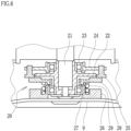
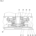
- Fig. 6 and Fig. 7 are enlarged views of the clutch 20.
- Fig. 6 illustrates a state in which the clutch 20 is disengaged
- Fig. 7 illustrates a state in which the clutch 20 is engaged.
- the clutch 20 is arranged inside the housing deck 7, and a motor shaft 21 of the electric motor 5 (see Fig. 2 ) that is arranged on the upper side of the housing deck 7 is connected to a drive disk 22.
- the motor shaft 21 and the drive disk 22 are connected by a key (not illustrated), and the drive disk 22 also rotates integrally with the rotation of the motor shaft 21.
- a brake disc support plate 24 is attached to the motor shaft 21 via an upper-side bearing 23.
- An annular brake disc 25 is attached to the brake disc support plate 24 so as to be movable in the vertical direction. In this configuration, even if the motor shaft 21 rotates, because the upper-side bearing 23 is interposed between the motor shaft 21 and the brake disc support plate 24, the brake disc support plate 24 and the brake disc 25 that is integrated with the brake disc support plate 24 do not rotate.
- the cutting blade 9 is fixed to the lower side of a blade holder 26, and a lower-side bearing 27 is interposed between the blade holder 26 and the drive disk 22.
- a friction plate 28 is connected to the upper side of the blade holder 26 in a turn-stopping fashion so as to be vertically slidable, and when the friction plate 28 rotates, the blade holder 26 and the cutting blade 9 rotate integrally with the friction plate 28.
- a spring 29 is interposed between the blade holder 26 and the friction plate 28, and the friction plate 28 slides in the vertical direction as the spring 29 expands and contracts.
- the friction plate 28 is pressed by the brake disc 25 and caused to slide downward, and the spring 29 is contracted. Therefore, the friction plate 28 is separated from the drive disk 22.
- This state is a state in which the clutch 20 is disengaged, and even if the drive disk 22 rotates integrally with rotation of the motor shaft 21, the rotation of the drive disk 22 is not transmitted to the friction plate 28, and the cutting blade 9 does not rotate either.
- the state illustrated in Fig. 7 is a state in which the pressing of the friction plate 28 by the brake disc 25 has been released, and as a result the spring 29 extends and the friction plate 28 presses the drive disc 22 due to the repulsive force of the spring 29.
- This state is a state in which the clutch 20 is engaged, and thus rotation of the drive disk 22 is transmitted to the friction plate 28, and the cutting blade 9 rotates to enable lawn mowing.
- the work machine 1 includes a switching mechanism (not illustrated) that switches between a state in which the brake disc 25 is pushed down to the lower side to disengage the clutch 20 (state in Fig. 6 ), and a state in which the disengaged state of the clutch 20 has been released and the clutch 20 is engaged (state in Fig. 7 ).
- This switching mechanism is operated by operating the clutch lever 12 (see Fig. 1 ).
- Fig. 1 when the clutch lever 12 is tilted to the front side in a state in which an operation button 18 at the upper portion of the clutch lever 12 is pressed, the switching mechanism is activated and the state in which the brake disc 25 is pushed down to the lower side is released, the friction plate 28 presses the drive disk 22 as illustrated in Fig. 7 , and the clutch 20 enters an engaged state and the cutting blade 9 rotates.
- the cutting blade 9 rotates as long as the state in which the operation button 18 is pressed and the clutch lever 12 is tilted to the front side is maintained, but when the operator's hand separates from the clutch lever 12, the clutch lever 12 returns to its original state, and the clutch 20 enters a disengaged state and rotation of the cutting blade 9 stops.
- the work machine 1 has built-in controller 30 (a computer) for controlling the operation of the electric motor 5.
- controller 30 a computer
- the control of the electric motor 5 by the controller 30 is described below.
- Fig. 8 is a block diagram illustrating control of the electric motor 5 by the controller 30
- Fig. 9 is an external perspective view illustrating the vicinity of the clutch lever 12 and a clutch operation detection sensor 31, and
- Fig. 10 a flowchart illustrating a process from starting operation until ending operation.
- a signal from the clutch operation detection sensor 31 is input to the controller 30, and the controller 30 controls the operation of the electric motor 5 in response to this signal.
- the clutch operation detection sensor 31 is provided below the clutch lever 12.
- the clutch operation detection sensor 31 includes a detection button 32, and in the state illustrated in Fig. 9 (state in which the clutch lever 12 is not operated), the detection button 32 is pressed by a pressing plate 33 that is fixed to the clutch lever 12.
- the controller 30 by setting the positional relationship between the clutch operation detection sensor 31 and the pressing plate 33 so that the detection button 32 rises upward when the state in which the clutch 20 is disengaged is released, the signal value of the clutch operation detection sensor 31 when the state changes becomes a signal value indicating that the disengaged state of the clutch 20 has been released, and it is thus possible for the controller 30 to recognize the release of state in which the clutch 20 is disengaged.
- Fig. 10 when starting operation (step 100), the main power source is turned on (step 101) by rotating the main switch 17 (see Fig. 3 ). By sliding the shift lever 13 (see Fig. 1 ) in this state, the electric motor 5 is started (step 102), and the electric motor 5 rotates (step 103). In this state, in Fig. 1 , by operating the operation lever 14, the rear wheels 4 are driven and the work machine 1 moves forward.
- a signal from the clutch operation detection sensor 31 is input to the controller 30, and the controller 30 can recognize the release of the disengaged state of the clutch 20.
- the controller 30 stops the energization of the electric motor 5 (stops the rotational driving) during a period from the time of recognizing the release until a prescribed time period elapses (step 106 in Fig. 10 ).
- This control is control that stops energization of the electric motor 5 during a period that includes the moment at which the clutch 20 is engaged, and it suffices that the period of stopping energization of the electric motor 5 includes the moment at which the clutch 20 is engaged.
- the rotation of the electric motor 5 stops during a period from when the disengaged state of the clutch 20 is released until a prescribed time period elapses, since a period from release of the disengaged state of the clutch 20 until the clutch 20 is engaged is a momentary period, even if the prescribed time period is a very small time period of about 0.5 seconds, the moment at which the clutch 20 is engaged will be included in the period in which rotation of the electric motor 5 is stopped.
- the prescribed time period for which rotation of the electric motor 5 is stopped is not particularly limited, for example the prescribed time period is within the range of 0.5 to 1 second.
- the controller 30 restarts the electric motor 5 (step 107), and the electric motor 5 rotates once more (step 103). In this state, the clutch 20 is in an engaged state, and the cutting blade 9 rotates due to the rotation of the electric motor 5.
- step 105 the main power source is turned off (step 104), and operation is ended (step 108).
- the Comparative Example has a configuration so that control that stops energization of the electric motor 5 (hereinafter, referred to as "energization stopping control”) is not executed during a period from when the disengaged state of the clutch 20 is released until a prescribed time period elapses. That is, rotation of the electric motor 5 continues irrespective of the operation of the clutch 20.
- the Example is configured so that energization stopping control is added to the configuration of the Comparative Example. With respect to the Comparative Example and the Example, a voltage measuring probe and a current measuring probe were connected thereto, and voltage values and current values were measured chronologically using a data logger.
- Fig. 11 illustrates waveforms of a current I and a voltage V of the electric motor 5 with respect to the Comparative Example.
- the abscissa axis represents the elapsed time t (s), and the ordinates axis is used to represent both the current I (A) and the voltage V (V) (the same applies with respect to Fig. 12 ).
- Fig. 11 that relates to the Comparative Example, during a period T1 after the start of measurement, the clutch 20 is in an engaged state and the cutting blade 9 is rotating.
- T2 period of 1 second
- the clutch 20 is in a disengaged state, and although rotation of the electric motor 5 continues, rotation of the cutting blade 9 is stopped.
- the voltage V is rising and the current I is falling.
- T3 period of 9 seconds
- the clutch 20 is in an engaged state.
- the voltage V drops (A part) and the current I rises sharply (B part). It is considered that this is because the load increased suddenly due to the clutch 20 being engaged. Thereafter, the current I falls and eventually stabilizes (C part).
- Fig. 12 that relates to the Example, although the waveforms of the current and voltage in the period T1 and the period T2 are the same as in Fig. 11 relating to the Comparative Example, the waveforms in the period T3 differ significantly between Fig. 11 and Fig. 12 .
- the current value falls to the vicinity of zero at the beginning of the period T3 (D part). This is because energization stopping control was executed, and energization of the electric motor 5 was stopped. It is surmised that the reason the current value did not become completely zero was because of energization of the sensors and the characteristics of the three-phase motor.
- the energization stop time was set to 0.5 seconds, and upon 0.5 seconds elapsing from the time that energization of the electric motor 5 was stopped, the electric motor 5 restarted and simultaneously the cutting blade 9 also rotated. After restarting, the current rises as a whole (E part), and thereafter falls (F part), and eventually stabilizes (G part).
- the effect of reducing the electric power consumption is obtained by suppressing an abrupt increase in the current at a moment at which the clutch 20 is engaged, the effect of reducing the electric power consumption increases as the frequency of engaging and disengaging the clutch 20 increases.
- the frequency of engaging and disengaging the clutch 20 is high, and hence electric power consumption can be reduced more effectively.
- the above embodiment is an example and may be appropriately modified.
- the clutch lever 12 is used as operation means for operating the clutch 20, as long as the clutch 20 can be operated, the operation means is not limited to a lever structure.
- the detection of release of a state in which the clutch 20 is disengaged is detection that is based on a change in a signal value that is output from the clutch operation detection sensor 31 as a result of operation of the clutch lever 12, it suffices that the release of a state in which the clutch 20 is disengaged can be detected, and another method may be adopted as the detection method.
- the energization stopping control adopted in the above embodiment is control that stops energization of the electric motor 5 when a state in which the clutch 20 is disengaged is released, an energization stopping period is not limited thereto, and it suffices that energization is stopped at least at the moment at which the clutch 20 is engaged.
Landscapes
- Life Sciences & Earth Sciences (AREA)
- Environmental Sciences (AREA)
- Harvester Elements (AREA)
- Dicing (AREA)
Claims (1)
- Eine elektrische Arbeitsmaschine (1) mit einem Schneideblatt, die Folgendes umfasst:Ein Schneideblatt (9);einen Elektromotor (5), der drehend das Schneideblatt (9) antreibt;eine Kupplung (20), die konfiguriert ist, um die Antriebskraft zwischen dem Elektromotor (5) und dem Schneideblatt (9) einzukuppeln und auszukuppeln;Betriebsmittel (12), die konfiguriert sind, um die Kupplung (20) so zu betätigen, dass sie schaltet zwischen einem Zustand, in dem die Kupplung (20) ausgekuppelt ist und die Antriebskraft des Elektromotors (5) nicht auf das Schneideblatt (9) übertragen wird und einem Zustand, in dem die Kupplung (20) eingekuppelt ist und die Antriebskraft des Elektromotors (5) zunm Schneideblatt (5) übertragen wird;einen Sensor (31), der konfiguriert ist, um Bewegungen der Betriebsmittel (12) zu erfassen undein Steuergerät (30), das konfiguriert ist, um den Betrieb des Elektromotors (6) zu steuern und die Freigabe des Zustandes, in dem die Kupplung ausgekuppelt ist, zu erkennen, basierend auf einem Signal des Sensors (31),wobei das Steuergerät (30) konfiguriert ist, um die Drehung des Elektromotors (5) während eines Zeitraumes zu stoppen, der einen Moment einschliesst, in dem die Kupplung (20) durch Abschalten der Erregung des Elektromotors eingekuppelt wird und freigegeben wird, nach dem Zustand, in dem die Kupplung (20) ausgekuppelt ist, und erneutes Starten des Elektromotors (5) nach Ablauf eines vorbestimten Zeitraumes nach Anhalten der Erregung.
Applications Claiming Priority (1)
| Application Number | Priority Date | Filing Date | Title |
|---|---|---|---|
| PCT/JP2019/018802 WO2020230208A1 (ja) | 2019-05-10 | 2019-05-10 | 刈刃付き電動作業機 |
Publications (3)
| Publication Number | Publication Date |
|---|---|
| EP3967124A1 EP3967124A1 (de) | 2022-03-16 |
| EP3967124A4 EP3967124A4 (de) | 2022-12-21 |
| EP3967124B1 true EP3967124B1 (de) | 2024-09-18 |
Family
ID=73289514
Family Applications (1)
| Application Number | Title | Priority Date | Filing Date |
|---|---|---|---|
| EP19928459.7A Active EP3967124B1 (de) | 2019-05-10 | 2019-05-10 | Kraftunterstützte arbeitsmaschine mit schneidklinge |
Country Status (8)
| Country | Link |
|---|---|
| US (1) | US20220338412A1 (de) |
| EP (1) | EP3967124B1 (de) |
| JP (1) | JP7184400B2 (de) |
| KR (1) | KR102677075B1 (de) |
| CN (1) | CN113473841B (de) |
| AU (1) | AU2019445992B2 (de) |
| TW (1) | TWI778288B (de) |
| WO (1) | WO2020230208A1 (de) |
Families Citing this family (1)
| Publication number | Priority date | Publication date | Assignee | Title |
|---|---|---|---|---|
| EP4311418A1 (de) | 2022-07-29 | 2024-01-31 | Techtronic Cordless GP | Zentrifugalkupplungsmechanismen |
Family Cites Families (19)
| Publication number | Priority date | Publication date | Assignee | Title |
|---|---|---|---|---|
| US4882897A (en) * | 1987-11-28 | 1989-11-28 | Kubota, Ltd. | Clutch control structure for a walking operator type lawn mower |
| US4995227A (en) | 1989-10-25 | 1991-02-26 | Foster Harry C | Power assisted reel type lawn mower |
| EP0817352A2 (de) * | 1992-08-18 | 1998-01-07 | Black & Decker Inc. | Verbesserungen in Batteriegetriebenen elektrischen Maschinen |
| EP0777410A2 (de) * | 1994-08-22 | 1997-06-11 | BRIGGS & STRATTON CORPORATION | Batteriebetriebener rasenmäher |
| JP3192961B2 (ja) * | 1996-02-22 | 2001-07-30 | 本田技研工業株式会社 | 歩行型作業機の操作レバー装置 |
| JP2001046784A (ja) * | 1999-08-10 | 2001-02-20 | Hitachi Ltd | 全自動洗濯機及び全自動洗濯機の制御方法 |
| JP2002303229A (ja) * | 2001-04-03 | 2002-10-18 | Orec Co Ltd | 作業機の始動安全装置、それを備えた作業機及び作業機の始動時の安全を図る方法 |
| TWI248783B (en) * | 2001-08-22 | 2006-02-11 | Honda Motor Co Ltd | Electric lawn mower |
| JP2003061432A (ja) * | 2001-08-22 | 2003-03-04 | Honda Motor Co Ltd | 電動芝刈機 |
| US7470209B2 (en) * | 2005-11-23 | 2008-12-30 | Gm Global Technology Operations, Inc. | Hybrid powertrain having an electrically variable transmission and engine valve control |
| JP2007222026A (ja) * | 2006-02-21 | 2007-09-06 | Kubota Corp | 電動作業機 |
| JP2013169612A (ja) * | 2012-02-20 | 2013-09-02 | Duplo Corp | 断裁装置 |
| JP6034752B2 (ja) | 2013-06-11 | 2016-11-30 | 株式会社クボタ | 歩行型草刈機 |
| EP2905493B1 (de) * | 2014-02-08 | 2019-01-09 | Andreas Stihl AG & Co. KG | Arbeitsgerät mit einer Kupplung |
| JP6206970B2 (ja) * | 2014-09-18 | 2017-10-04 | 東洋電装株式会社 | 動力作業機用回転電機 |
| KR101729005B1 (ko) * | 2015-02-16 | 2017-04-21 | 인하공업전문대학산학협력단 | 구동모터를 이용한 배부식 예초기 |
| JP6193421B2 (ja) * | 2016-02-29 | 2017-09-06 | 本田技研工業株式会社 | 芝刈機 |
| WO2018021427A1 (ja) * | 2016-07-26 | 2018-02-01 | 株式会社コーク | 高圧エヤ発生装置 |
| US9687111B1 (en) * | 2017-02-09 | 2017-06-27 | R. Joseph Trojan | Vacuum blender |
-
2019
- 2019-05-10 EP EP19928459.7A patent/EP3967124B1/de active Active
- 2019-05-10 US US17/432,301 patent/US20220338412A1/en not_active Abandoned
- 2019-05-10 JP JP2021519051A patent/JP7184400B2/ja active Active
- 2019-05-10 KR KR1020217026575A patent/KR102677075B1/ko active Active
- 2019-05-10 AU AU2019445992A patent/AU2019445992B2/en active Active
- 2019-05-10 CN CN201980092297.XA patent/CN113473841B/zh active Active
- 2019-05-10 WO PCT/JP2019/018802 patent/WO2020230208A1/ja not_active Ceased
- 2019-08-07 TW TW108128023A patent/TWI778288B/zh active
Also Published As
| Publication number | Publication date |
|---|---|
| EP3967124A1 (de) | 2022-03-16 |
| TWI778288B (zh) | 2022-09-21 |
| JPWO2020230208A1 (de) | 2020-11-19 |
| CN113473841B (zh) | 2023-01-31 |
| KR102677075B1 (ko) | 2024-06-21 |
| KR20210114526A (ko) | 2021-09-23 |
| US20220338412A1 (en) | 2022-10-27 |
| JP7184400B2 (ja) | 2022-12-06 |
| TW202041139A (zh) | 2020-11-16 |
| EP3967124A4 (de) | 2022-12-21 |
| CN113473841A (zh) | 2021-10-01 |
| AU2019445992A1 (en) | 2021-09-09 |
| BR112021021023A2 (pt) | 2021-12-14 |
| AU2019445992B2 (en) | 2022-12-01 |
| WO2020230208A1 (ja) | 2020-11-19 |
Similar Documents
| Publication | Publication Date | Title |
|---|---|---|
| AU2019445481B2 (en) | Electric work machine with cutting blade | |
| US11039715B2 (en) | Food processing machine adaptive to food load | |
| CN112740893B (zh) | 骑乘式割草机 | |
| US5156221A (en) | Method of and arrangement for controlling the operation of a hand-held electrical device | |
| CN104159484A (zh) | 食品加工机或切碎机 | |
| CN104626032A (zh) | 作业工具 | |
| EP3967124B1 (de) | Kraftunterstützte arbeitsmaschine mit schneidklinge | |
| JP5648672B2 (ja) | 草刈機 | |
| JP2014113068A5 (de) | ||
| JP5304199B2 (ja) | エンジン作業機 | |
| JP5605751B2 (ja) | 携帯用切断機 | |
| JPWO2021029182A5 (de) | ||
| JP6555318B2 (ja) | 草刈機 | |
| US20240276913A1 (en) | Lawn mower | |
| BR112021021023B1 (pt) | Máquina de trabalho elétrica com lâmina de corte | |
| JP6135784B2 (ja) | 草刈機 | |
| JP6131584B2 (ja) | 草刈機 | |
| EP4242495B1 (de) | Fahrassistenzsystem und verfahren | |
| US3095676A (en) | Automatic balancing arrangement for grinding wheels | |
| JP6245290B2 (ja) | 草刈機 | |
| JPH0741312Y2 (ja) | 扱深さ自動制御装置 | |
| US2403160A (en) | Grinding machine | |
| JPS6315036Y2 (de) | ||
| JPS644571A (en) | Drive controller for remote steering working truck | |
| JPH0260U (de) |
Legal Events
| Date | Code | Title | Description |
|---|---|---|---|
| STAA | Information on the status of an ep patent application or granted ep patent |
Free format text: STATUS: THE INTERNATIONAL PUBLICATION HAS BEEN MADE |
|
| PUAI | Public reference made under article 153(3) epc to a published international application that has entered the european phase |
Free format text: ORIGINAL CODE: 0009012 |
|
| STAA | Information on the status of an ep patent application or granted ep patent |
Free format text: STATUS: REQUEST FOR EXAMINATION WAS MADE |
|
| 17P | Request for examination filed |
Effective date: 20211005 |
|
| AK | Designated contracting states |
Kind code of ref document: A1 Designated state(s): AL AT BE BG CH CY CZ DE DK EE ES FI FR GB GR HR HU IE IS IT LI LT LU LV MC MK MT NL NO PL PT RO RS SE SI SK SM TR |
|
| DAV | Request for validation of the european patent (deleted) | ||
| DAX | Request for extension of the european patent (deleted) | ||
| REG | Reference to a national code |
Ref country code: DE Free format text: PREVIOUS MAIN CLASS: A01D0034680000 Ref country code: DE Ref legal event code: R079 Ref document number: 602019059307 Country of ref document: DE Free format text: PREVIOUS MAIN CLASS: A01D0034680000 Ipc: A01D0034000000 |
|
| A4 | Supplementary search report drawn up and despatched |
Effective date: 20221118 |
|
| RIC1 | Information provided on ipc code assigned before grant |
Ipc: A01D 34/78 20060101ALI20221114BHEP Ipc: A01D 34/68 20060101ALI20221114BHEP Ipc: A01D 34/00 20060101AFI20221114BHEP |
|
| GRAP | Despatch of communication of intention to grant a patent |
Free format text: ORIGINAL CODE: EPIDOSNIGR1 |
|
| STAA | Information on the status of an ep patent application or granted ep patent |
Free format text: STATUS: GRANT OF PATENT IS INTENDED |
|
| RIC1 | Information provided on ipc code assigned before grant |
Ipc: A01D 34/78 20060101ALI20240620BHEP Ipc: A01D 34/68 20060101ALI20240620BHEP Ipc: A01D 34/00 20060101AFI20240620BHEP |
|
| GRAS | Grant fee paid |
Free format text: ORIGINAL CODE: EPIDOSNIGR3 |
|
| INTG | Intention to grant announced |
Effective date: 20240718 |
|
| GRAA | (expected) grant |
Free format text: ORIGINAL CODE: 0009210 |
|
| STAA | Information on the status of an ep patent application or granted ep patent |
Free format text: STATUS: THE PATENT HAS BEEN GRANTED |
|
| AK | Designated contracting states |
Kind code of ref document: B1 Designated state(s): AL AT BE BG CH CY CZ DE DK EE ES FI FR GB GR HR HU IE IS IT LI LT LU LV MC MK MT NL NO PL PT RO RS SE SI SK SM TR |
|
| REG | Reference to a national code |
Ref country code: GB Ref legal event code: FG4D |
|
| REG | Reference to a national code |
Ref country code: CH Ref legal event code: EP |
|
| REG | Reference to a national code |
Ref country code: IE Ref legal event code: FG4D |
|
| REG | Reference to a national code |
Ref country code: DE Ref legal event code: R096 Ref document number: 602019059307 Country of ref document: DE |
|
| REG | Reference to a national code |
Ref country code: LT Ref legal event code: MG9D |
|
| PG25 | Lapsed in a contracting state [announced via postgrant information from national office to epo] |
Ref country code: NO Free format text: LAPSE BECAUSE OF FAILURE TO SUBMIT A TRANSLATION OF THE DESCRIPTION OR TO PAY THE FEE WITHIN THE PRESCRIBED TIME-LIMIT Effective date: 20241218 |
|
| PG25 | Lapsed in a contracting state [announced via postgrant information from national office to epo] |
Ref country code: GR Free format text: LAPSE BECAUSE OF FAILURE TO SUBMIT A TRANSLATION OF THE DESCRIPTION OR TO PAY THE FEE WITHIN THE PRESCRIBED TIME-LIMIT Effective date: 20241219 Ref country code: FI Free format text: LAPSE BECAUSE OF FAILURE TO SUBMIT A TRANSLATION OF THE DESCRIPTION OR TO PAY THE FEE WITHIN THE PRESCRIBED TIME-LIMIT Effective date: 20240918 |
|
| PG25 | Lapsed in a contracting state [announced via postgrant information from national office to epo] |
Ref country code: BG Free format text: LAPSE BECAUSE OF FAILURE TO SUBMIT A TRANSLATION OF THE DESCRIPTION OR TO PAY THE FEE WITHIN THE PRESCRIBED TIME-LIMIT Effective date: 20240918 |
|
| PG25 | Lapsed in a contracting state [announced via postgrant information from national office to epo] |
Ref country code: LV Free format text: LAPSE BECAUSE OF FAILURE TO SUBMIT A TRANSLATION OF THE DESCRIPTION OR TO PAY THE FEE WITHIN THE PRESCRIBED TIME-LIMIT Effective date: 20240918 |
|
| PG25 | Lapsed in a contracting state [announced via postgrant information from national office to epo] |
Ref country code: HR Free format text: LAPSE BECAUSE OF FAILURE TO SUBMIT A TRANSLATION OF THE DESCRIPTION OR TO PAY THE FEE WITHIN THE PRESCRIBED TIME-LIMIT Effective date: 20240918 |
|
| REG | Reference to a national code |
Ref country code: NL Ref legal event code: MP Effective date: 20240918 |
|
| PG25 | Lapsed in a contracting state [announced via postgrant information from national office to epo] |
Ref country code: RS Free format text: LAPSE BECAUSE OF FAILURE TO SUBMIT A TRANSLATION OF THE DESCRIPTION OR TO PAY THE FEE WITHIN THE PRESCRIBED TIME-LIMIT Effective date: 20241218 |
|
| PG25 | Lapsed in a contracting state [announced via postgrant information from national office to epo] |
Ref country code: RS Free format text: LAPSE BECAUSE OF FAILURE TO SUBMIT A TRANSLATION OF THE DESCRIPTION OR TO PAY THE FEE WITHIN THE PRESCRIBED TIME-LIMIT Effective date: 20241218 Ref country code: NO Free format text: LAPSE BECAUSE OF FAILURE TO SUBMIT A TRANSLATION OF THE DESCRIPTION OR TO PAY THE FEE WITHIN THE PRESCRIBED TIME-LIMIT Effective date: 20241218 Ref country code: LV Free format text: LAPSE BECAUSE OF FAILURE TO SUBMIT A TRANSLATION OF THE DESCRIPTION OR TO PAY THE FEE WITHIN THE PRESCRIBED TIME-LIMIT Effective date: 20240918 Ref country code: HR Free format text: LAPSE BECAUSE OF FAILURE TO SUBMIT A TRANSLATION OF THE DESCRIPTION OR TO PAY THE FEE WITHIN THE PRESCRIBED TIME-LIMIT Effective date: 20240918 Ref country code: GR Free format text: LAPSE BECAUSE OF FAILURE TO SUBMIT A TRANSLATION OF THE DESCRIPTION OR TO PAY THE FEE WITHIN THE PRESCRIBED TIME-LIMIT Effective date: 20241219 Ref country code: FI Free format text: LAPSE BECAUSE OF FAILURE TO SUBMIT A TRANSLATION OF THE DESCRIPTION OR TO PAY THE FEE WITHIN THE PRESCRIBED TIME-LIMIT Effective date: 20240918 Ref country code: BG Free format text: LAPSE BECAUSE OF FAILURE TO SUBMIT A TRANSLATION OF THE DESCRIPTION OR TO PAY THE FEE WITHIN THE PRESCRIBED TIME-LIMIT Effective date: 20240918 |
|
| REG | Reference to a national code |
Ref country code: AT Ref legal event code: MK05 Ref document number: 1723862 Country of ref document: AT Kind code of ref document: T Effective date: 20240918 |
|
| PG25 | Lapsed in a contracting state [announced via postgrant information from national office to epo] |
Ref country code: NL Free format text: LAPSE BECAUSE OF FAILURE TO SUBMIT A TRANSLATION OF THE DESCRIPTION OR TO PAY THE FEE WITHIN THE PRESCRIBED TIME-LIMIT Effective date: 20240918 |
|
| PG25 | Lapsed in a contracting state [announced via postgrant information from national office to epo] |
Ref country code: IS Free format text: LAPSE BECAUSE OF FAILURE TO SUBMIT A TRANSLATION OF THE DESCRIPTION OR TO PAY THE FEE WITHIN THE PRESCRIBED TIME-LIMIT Effective date: 20250118 Ref country code: PT Free format text: LAPSE BECAUSE OF FAILURE TO SUBMIT A TRANSLATION OF THE DESCRIPTION OR TO PAY THE FEE WITHIN THE PRESCRIBED TIME-LIMIT Effective date: 20250120 |
|
| PG25 | Lapsed in a contracting state [announced via postgrant information from national office to epo] |
Ref country code: SM Free format text: LAPSE BECAUSE OF FAILURE TO SUBMIT A TRANSLATION OF THE DESCRIPTION OR TO PAY THE FEE WITHIN THE PRESCRIBED TIME-LIMIT Effective date: 20240918 Ref country code: RO Free format text: LAPSE BECAUSE OF FAILURE TO SUBMIT A TRANSLATION OF THE DESCRIPTION OR TO PAY THE FEE WITHIN THE PRESCRIBED TIME-LIMIT Effective date: 20240918 |
|
| PG25 | Lapsed in a contracting state [announced via postgrant information from national office to epo] |
Ref country code: ES Free format text: LAPSE BECAUSE OF FAILURE TO SUBMIT A TRANSLATION OF THE DESCRIPTION OR TO PAY THE FEE WITHIN THE PRESCRIBED TIME-LIMIT Effective date: 20240918 |
|
| PG25 | Lapsed in a contracting state [announced via postgrant information from national office to epo] |
Ref country code: AT Free format text: LAPSE BECAUSE OF FAILURE TO SUBMIT A TRANSLATION OF THE DESCRIPTION OR TO PAY THE FEE WITHIN THE PRESCRIBED TIME-LIMIT Effective date: 20240918 Ref country code: EE Free format text: LAPSE BECAUSE OF FAILURE TO SUBMIT A TRANSLATION OF THE DESCRIPTION OR TO PAY THE FEE WITHIN THE PRESCRIBED TIME-LIMIT Effective date: 20240918 |
|
| PG25 | Lapsed in a contracting state [announced via postgrant information from national office to epo] |
Ref country code: CZ Free format text: LAPSE BECAUSE OF FAILURE TO SUBMIT A TRANSLATION OF THE DESCRIPTION OR TO PAY THE FEE WITHIN THE PRESCRIBED TIME-LIMIT Effective date: 20240918 Ref country code: PL Free format text: LAPSE BECAUSE OF FAILURE TO SUBMIT A TRANSLATION OF THE DESCRIPTION OR TO PAY THE FEE WITHIN THE PRESCRIBED TIME-LIMIT Effective date: 20240918 |
|
| PG25 | Lapsed in a contracting state [announced via postgrant information from national office to epo] |
Ref country code: IT Free format text: LAPSE BECAUSE OF FAILURE TO SUBMIT A TRANSLATION OF THE DESCRIPTION OR TO PAY THE FEE WITHIN THE PRESCRIBED TIME-LIMIT Effective date: 20240918 Ref country code: SK Free format text: LAPSE BECAUSE OF FAILURE TO SUBMIT A TRANSLATION OF THE DESCRIPTION OR TO PAY THE FEE WITHIN THE PRESCRIBED TIME-LIMIT Effective date: 20240918 |
|
| REG | Reference to a national code |
Ref country code: DE Ref legal event code: R097 Ref document number: 602019059307 Country of ref document: DE |
|
| PG25 | Lapsed in a contracting state [announced via postgrant information from national office to epo] |
Ref country code: DK Free format text: LAPSE BECAUSE OF FAILURE TO SUBMIT A TRANSLATION OF THE DESCRIPTION OR TO PAY THE FEE WITHIN THE PRESCRIBED TIME-LIMIT Effective date: 20240918 |
|
| PGFP | Annual fee paid to national office [announced via postgrant information from national office to epo] |
Ref country code: GB Payment date: 20250411 Year of fee payment: 7 |
|
| PGFP | Annual fee paid to national office [announced via postgrant information from national office to epo] |
Ref country code: FR Payment date: 20250411 Year of fee payment: 7 |
|
| PLBE | No opposition filed within time limit |
Free format text: ORIGINAL CODE: 0009261 |
|
| STAA | Information on the status of an ep patent application or granted ep patent |
Free format text: STATUS: NO OPPOSITION FILED WITHIN TIME LIMIT |
|
| 26N | No opposition filed |
Effective date: 20250619 |
|
| PG25 | Lapsed in a contracting state [announced via postgrant information from national office to epo] |
Ref country code: SE Free format text: LAPSE BECAUSE OF FAILURE TO SUBMIT A TRANSLATION OF THE DESCRIPTION OR TO PAY THE FEE WITHIN THE PRESCRIBED TIME-LIMIT Effective date: 20240918 |
|
| REG | Reference to a national code |
Ref country code: DE Ref legal event code: R119 Ref document number: 602019059307 Country of ref document: DE |
|
| REG | Reference to a national code |
Ref country code: CH Ref legal event code: H13 Free format text: ST27 STATUS EVENT CODE: U-0-0-H10-H13 (AS PROVIDED BY THE NATIONAL OFFICE) Effective date: 20251223 |
|
| PG25 | Lapsed in a contracting state [announced via postgrant information from national office to epo] |
Ref country code: LU Free format text: LAPSE BECAUSE OF NON-PAYMENT OF DUE FEES Effective date: 20250510 |
|
| PG25 | Lapsed in a contracting state [announced via postgrant information from national office to epo] |
Ref country code: CH Free format text: LAPSE BECAUSE OF NON-PAYMENT OF DUE FEES Effective date: 20250531 |
|
| PG25 | Lapsed in a contracting state [announced via postgrant information from national office to epo] |
Ref country code: MC Free format text: LAPSE BECAUSE OF FAILURE TO SUBMIT A TRANSLATION OF THE DESCRIPTION OR TO PAY THE FEE WITHIN THE PRESCRIBED TIME-LIMIT Effective date: 20240918 |