EP3965939B1 - Stützvorrichtung für zwei getriebe sowie vorrichtung mit einer solchen stützvorrichtung - Google Patents
Stützvorrichtung für zwei getriebe sowie vorrichtung mit einer solchen stützvorrichtung Download PDFInfo
- Publication number
- EP3965939B1 EP3965939B1 EP20721442.0A EP20721442A EP3965939B1 EP 3965939 B1 EP3965939 B1 EP 3965939B1 EP 20721442 A EP20721442 A EP 20721442A EP 3965939 B1 EP3965939 B1 EP 3965939B1
- Authority
- EP
- European Patent Office
- Prior art keywords
- support
- supporting
- flange
- parts
- lever
- Prior art date
- Legal status (The legal status is an assumption and is not a legal conclusion. Google has not performed a legal analysis and makes no representation as to the accuracy of the status listed.)
- Active
Links
Images


Classifications
-
- F—MECHANICAL ENGINEERING; LIGHTING; HEATING; WEAPONS; BLASTING
- F16—ENGINEERING ELEMENTS AND UNITS; GENERAL MEASURES FOR PRODUCING AND MAINTAINING EFFECTIVE FUNCTIONING OF MACHINES OR INSTALLATIONS; THERMAL INSULATION IN GENERAL
- F16H—GEARING
- F16H57/00—General details of gearing
- F16H57/02—Gearboxes; Mounting gearing therein
- F16H57/025—Support of gearboxes, e.g. torque arms, or attachment to other devices
-
- B—PERFORMING OPERATIONS; TRANSPORTING
- B02—CRUSHING, PULVERISING, OR DISINTEGRATING; PREPARATORY TREATMENT OF GRAIN FOR MILLING
- B02C—CRUSHING, PULVERISING, OR DISINTEGRATING IN GENERAL; MILLING GRAIN
- B02C4/00—Crushing or disintegrating by roller mills
- B02C4/28—Details
- B02C4/42—Driving mechanisms; Roller speed control
- B02C4/426—Torque counterbalancing mechanisms
-
- F—MECHANICAL ENGINEERING; LIGHTING; HEATING; WEAPONS; BLASTING
- F16—ENGINEERING ELEMENTS AND UNITS; GENERAL MEASURES FOR PRODUCING AND MAINTAINING EFFECTIVE FUNCTIONING OF MACHINES OR INSTALLATIONS; THERMAL INSULATION IN GENERAL
- F16H—GEARING
- F16H35/00—Gearings or mechanisms with other special functional features
- F16H35/06—Gearings designed to allow relative movement between supports thereof without ill effects
-
- B—PERFORMING OPERATIONS; TRANSPORTING
- B02—CRUSHING, PULVERISING, OR DISINTEGRATING; PREPARATORY TREATMENT OF GRAIN FOR MILLING
- B02C—CRUSHING, PULVERISING, OR DISINTEGRATING IN GENERAL; MILLING GRAIN
- B02C4/00—Crushing or disintegrating by roller mills
- B02C4/02—Crushing or disintegrating by roller mills with two or more rollers
Definitions
- the invention relates to a support device for two gears according to the preamble of patent claim 1.
- the invention also relates to a device with such a support device according to the preamble of patent claim 11.
- the EP 0 775 525 A1 discloses a torque support for two rollers driven in opposite directions, one of which is arranged in a fixed manner and the other is arranged in a machine frame so that it can be displaced in relation to the fixed roller.
- the rolls are each provided with a roll neck on the same roll side, onto which a gear is attached.
- Torque arms are firmly connected to the gearboxes, each of which has two pivot points that are articulated to one another by means of coupling rods. It is provided that all pivot points of the coupling rods are arranged on one side of a center plane running through the axes of the rollers.
- EP 0 992 710 A2 a double-sided torque support for a gear slipped onto the machine shaft of a working machine can be seen as known.
- the object of the present invention is to create a support device and a device with such a support device, so that particularly low-load operation can be implemented.
- a first aspect of the invention relates to a support device for, in particular at least or precisely, two gears and thus, for example, for a pair of gears formed by the gears.
- the support device which is also referred to, for example, as a torque support or functions as a torque support, has a first support flange which can be coupled to a first of the transmissions, in particular in a torque-transmitting manner.
- the first support flange can be coupled to a first housing of the first transmission, in particular in a torque-transmitting manner.
- the first support flange can be coupled or is coupled in a rotationally fixed manner to the first gear, in particular to the first housing of the first gear.
- the first support flange can be firmly or rigidly connected or connected to the first gear, in particular to the first housing of the first gear.
- the support device also has a second support flange, which can be coupled to the second transmission, in particular in a torque-transmitting manner.
- the second support flange can be coupled to a second housing of the second transmission, in particular in a torque-transmitting manner.
- the second support flange can be coupled or is coupled in a rotationally fixed manner to the second transmission, in particular to the second housing.
- the second support flange can be rigidly or firmly coupled or coupled to the second gear, in particular to the second housing.
- the support device has at least one support via which a support force can be transmitted from the first support flange to the second support flange.
- the at least one support has a lever element, also referred to as a strut or strut element, which is coupled in an articulated manner to a connection element provided on the first support flange and is therefore articulated to the first support flange.
- connection element is coupled in an articulated manner to the connection element and to the first support flange by means of, in particular precisely, a joint.
- the connection element is, for example, what is known as an ear, which protrudes, for example, from the support flange itself, in particular in the radial direction of the first gear.
- connection element is formed in one piece with the first support flange, or the connection element and the first support flange are formed separately from one another and are connected to one another, in particular in a torque-proof manner.
- the at least one support also has a support element which is coupled in an articulated manner to the lever element and which, for example is coupled in an articulated manner to the lever element by means, in particular precisely, of a second joint.
- the support element is connected to the second support flange.
- the support element is connected to the second support flange in a torque-transmitting manner, in particular in a torque-proof manner. In this way, for example, the torque or reaction torque can be transmitted from the first housing to the first support flange, from the first support flange via the connection element to the lever element, from the lever element to the support element and from the support element to the second support flange and thereby supported.
- the lever element is preferably designed separately from the connection element, separately from the support flanges and separately from the support element, with the support flanges also being referred to as flanges. Furthermore, the support element can be formed separately from the lever element and separately from the support flanges.
- connection element has two connection parts which are spaced apart from one another, in particular in the axial direction of the first gear.
- the connection parts can be formed in one piece with one another, or the connection parts are formed as components which are formed separately from one another and are connected to one another, in particular via the first support flange.
- the support element has two support parts that are spaced apart from one another, in particular in the axial direction of the first gear.
- the support parts can be formed in one piece with one another, or the support parts can be formed as components which are formed separately from one another and are connected to one another, in particular via the second support flange.
- the lever element is arranged partially between the connection parts and partially between the support parts. The lever element is articulated to the connection element and thus to the first support flange via the connection parts. In addition, the lever element is coupled in an articulated manner to the support element via the support parts. Due to the fact that the support element has the support parts spaced apart from one another, the support element has a double-shear design.
- the invention is based in particular on the following findings: For reasons of installation space and thus space, it may be desirable to arrange the support flanges and in particular the support in such a way that the lever element is subjected to pressure rather than tension. This can lead to a pressure load on an end of the support which faces or is assigned to the second support flange, which in turn can lead to a tensile load on the second support flange. Such a tensile load and the resulting tensile stresses of the respective support flange can be undesirable or unfavorable and in particular lead to additional bending stress on the respective support flange.
- the respective support flange would have to be made from a particularly strong, in particular high-strength material, which can lead to undesirably high costs for the support device. Furthermore, it is conceivable to dimension the respective support flange to be particularly large or massive, which, however, can lead to an undesirably high weight and to an undesirably high installation space requirement for the support device.
- the described double-shear design of the support element now makes it possible to avoid excessive loads, in particular on the second support flange, so that the respective support flange or the support device can be designed in a particularly filigree manner and thus in terms of weight, cost and installation space.
- a load introduction in particular into the second support flange, can be realized so that mutually canceling bending moments occur. This can cause unwanted and excessive Bending stresses can be avoided in the second support flange.
- the double-shear feature, in particular on the second support flange also means that, for example, twice as much force can be transmitted via friction as compared to a single-shear design of the support element.
- screws that are used, in particular fitting screws can be relieved, so that the support device can be configured in a particularly filigree manner.
- the support element has the two spaced-apart support parts, between which the lever element is arranged, and because the lever element is coupled in an articulated manner to the support element via the spaced-apart support parts, a double-shear, articulated connection of the support element to the lever element is realized.
- This two-part connection can preferably also be transferred to the second support flange.
- the support areas are formed in one piece with one another, or the support areas are formed as components which are formed separately from one another and are connected to one another, in particular via the second support flange.
- a first of the support parts and a first of the support areas are formed in one piece with one another and are thus formed, for example, by a one-piece first component, with the second support part and the second support area being formed in one piece with one another and thus are formed for example by a one-piece second component.
- the components are formed separately from one another and, in particular via the second support flange and/or via the lever element, are formed as components connected to one another.
- the respective component can be formed from sheet metal and can therefore be designed, for example, as a sheet metal or as a sheet metal component.
- the respective connection part is formed from sheet metal and is therefore designed as a sheet metal or as a sheet metal component.
- the first support element is preferably connected to the second support flange, which can be arranged between the support areas, via the support areas spaced apart from one another in particular in the axial direction of the second gear, in particular in a torque-transmitting or non-rotatable manner.
- the two-part configuration of the support element allows a particularly advantageous support to be implemented with a particularly advantageous application of force to the support element, in particular in such a way that excessive bending stress can be avoided.
- the components are designed symmetrically, it being possible, as an alternative or in addition, for the connection parts to be designed symmetrically to one another.
- an at least almost bending moment-free load introduction into the support and the corresponding, second support flange can be realized, so that an excessive load on the second support flange, which is particularly subjected to tensile loads, can be avoided.
- an undesired oversizing of the support device can be avoided.
- the lever element can be designed as a particularly simple and therefore low-weight and cost-effective strut construction.
- the respective wall thicknesses, in particular sheet metal thicknesses, of the components can be kept low, so that the weight of the support can be kept particularly low.
- a double-shear load on the aforementioned screws, in particular fitting screws can be implemented, so that the material used can be used particularly well.
- the respective, double-shear connection or loading is to be understood in particular as meaning that the support is connected to the lever element or to the second support flange via at least or exactly two parting lines.
- the two-shear load on the screws can be understood to mean that the screws are loaded through or via two parting lines, as a result of which the load on the screws can be kept particularly low.
- one embodiment of the invention provides for the lever element to be designed in one piece.
- a further embodiment is characterized in that the respective support flange is designed as a cast component.
- the respective support flange can be formed in particular from cast iron.
- the costs of the support device can be kept particularly low.
- an excessive load, in particular of the second support flange, which is subjected to tensile loads, can be avoided.
- the support element in the installed position of the support device, is arranged at least predominantly, in particular completely, below the support flanges in the vertical direction.
- the support device assumes its installed position in the fully manufactured state of a device designed, for example, as a system, machine or device, which has the support device and the gears in its fully manufactured state.
- the installation position of the support device and thus of the device is one for the intended purpose Using the device and in particular the support device intended position or orientation of the device and thus the support device, in particular in space. Due to the fact that the support element is arranged at least predominantly, in particular completely, below the support flanges in relation to the installation position in the vertical direction, the installation space requirement of the support device can be kept particularly low.
- the feature that the support element is arranged at least predominantly below the support flanges in the installed position of the support device can be understood in particular to mean that the support element is arranged more than half of its volume or its outer peripheral shape below the support flanges.
- the support device has a second support via which a second support force can be transmitted from the second support flange to the first support flange.
- a torque or reaction torque can be transmitted from the second gear, in particular from the second housing of the second gear, via the second support flange to the second support and from the second support to the first support flange, as a result of which the second housing is supported and in particular counteracted rotation can be secured.
- the relevant explanations for the first gear and the first support can also be transferred to the second gear and the second support, mutatis mutandis, and vice versa.
- the second support has a second lever element, also referred to as a second strut or second strut element, which is articulated to a second connection element provided on the second support flange and is thus articulated to the second support flange.
- the second lever element is coupled in an articulated manner to the connection element and thus to the second support flange by means, in particular precisely, of a third joint.
- the second Support also has a support element which is coupled in an articulated manner to the second lever element and which is connected to the first support flange, in particular in a torque-transmitting and/or non-rotatable manner.
- the second support element is coupled in an articulated manner to the second lever element by means, in particular precisely, of a fourth joint.
- the second support element is arranged at least predominantly, in particular completely, above the support flanges in the vertical direction.
- the space requirement of the support device can be kept within a particularly small framework.
- the feature that in the installed position of the support device the second support element is arranged at least predominantly above the support flanges in the vertical direction can be understood in particular to mean that the second support element in the installed position of the support device is more than half of its volume or its outer peripheral shape above in the vertical direction the support flange is arranged.
- the lever element has two first lever parts which are spaced apart from one another and which are spaced apart from one another in particular in the axial direction of the second gear.
- the second support element is arranged between the first lever parts and is coupled in an articulated manner to the second lever element via the first lever parts.
- the lever element also has two second lever parts which are spaced apart from one another, in particular in the axial direction of the second gear mechanism, between which the second connection element is arranged.
- the second connection element is coupled in an articulated manner to the second lever element via the second lever parts.
- the first lever parts are, for example, formed in one piece with one another, it being possible, alternatively or additionally, for the second lever parts to be formed in one piece with one another. It is also conceivable that the first lever parts are designed as components that are designed separately from one another and are connected to one another, and/or the second lever parts are designed as components that are designed separately from one another and are connected to one another. In particular, it is conceivable that a first of the first lever parts and a first of the second lever parts are formed by a first, one-piece component. It is also possible that the second of the first lever parts and the second of the second lever parts are formed by a one-piece, second component. The components are formed separately from one another and are connected to one another, for example.
- the second support element and/or the second connection element is designed in one piece.
- the second connection element is formed in one piece with the second support flange.
- the second connection element and the second support flange are designed as components which are designed separately from one another and are connected to one another.
- the second connection element protrudes from the second support flange itself.
- one embodiment of the invention provides for the second connection element to have two second connection parts spaced apart from one another.
- the second connection parts can be in one piece be formed with one another, or the second connection parts are formed as separately formed components that are connected to one another, in particular via the second support flange.
- the second support element it is possible in this embodiment for the second support element to have two second support parts spaced apart from one another.
- the second support parts can be formed in one piece with one another, or the second support parts are formed as components which are formed separately from one another and are connected to one another, in particular via the second support flange.
- the second connection parts can be formed from sheet metal, for example, and can therefore be designed as sheet metal parts or sheets.
- the second support parts can be formed from sheet metal and can therefore be in the form of sheet metal or sheet metal components.
- the second lever element is arranged partially between the second connection parts and partially between the second support parts and is articulated to the second connection element via the second connection parts and articulated to the second support element via the second support parts.
- a double-shear connection of the second support element to the second lever element and preferably also to the first support flange is provided, so that excessive loads and in particular excessive bending stresses of the first support flange can be avoided.
- the second support element it is conceivable for the second support element to have two second support regions which are spaced apart from one another, in particular in the axial direction of the first transmission, with the first support flange being arranged between the second support regions.
- the second support element is connected to the first support flange via the second support regions, in particular in a torque-transmitting or non-rotatable manner.
- One of the second support portion and one of the second support part may be formed by an integral first member, while the other second support portion and the other second support portion may be formed by an integral second member.
- the elements are, for example, elements which are formed separately from one another and are connected to one another.
- the respective element can, for example, be formed from sheet metal and thus be designed as a sheet metal or as a sheet metal component.
- the second lever element In order to be able to keep the number of parts and thus the costs particularly low, provision is preferably made for the second lever element to be designed in one piece.
- a second aspect of the invention relates to a device designed, for example, as an industrial device or industrial application, which can be a machine, a device, or a system, for example.
- the device can be a transmission device.
- the device has a first transmission, into which drive power can be introduced via a first drive shaft having a first direction of rotation.
- the device comprises a second transmission into which drive power can be introduced via a second drive shaft having a second direction of rotation opposite to the first direction of rotation.
- the drive shafts also referred to simply as shafts, rotate in opposite directions, in particular during operation of the device.
- the waves also referred to as machine waves, run in opposite directions to one another.
- the first gear is arranged on the first drive shaft, it being possible for the first gear to be slipped onto the first drive shaft.
- the second gear can be arranged on the second drive shaft, it being conceivable that the second gear is slipped onto the second drive shaft.
- the drive shafts are, for example, spaced apart from one another, in particular along their respective radial direction, and run parallel to one another.
- the first drive shaft can be rotated about a first axis of rotation in the first direction of rotation
- the second drive shaft can be rotated or driven about a second axis of rotation in the second direction of rotation.
- the axes of rotation are preferably spaced apart from one another, with the axes of rotation preferably running parallel to one another.
- an axis-parallel arrangement of the drive shafts and, as a result, preferably also an axis-parallel arrangement of the gears are provided.
- the device comprises a support device, in particular according to the first aspect of the invention.
- the support device enables torque support of at least one of the gears, in particular both gears, in a particularly space-efficient manner.
- the support device is preferably designed as a welded construction, via which, for example, the transmissions, in particular their housings, are connected or coupled to one another.
- the gears, in particular the housing are kinematically coupled to one another via the support device.
- the support device has a first support flange coupled to the first gear, in particular in a torque-transmitting manner, and a second support flange coupled to the second gear, in particular in a torque-transmitting manner.
- the transmission has at least one support, via which a support force can be transmitted from the first support flange to the second support flange.
- the at least one support has a lever element which is articulated to a connection element provided on the first support flange and is thus articulated to the first support flange.
- the at least one support has a support element which is coupled in an articulated manner to the lever element and is connected to the second support flange, in particular in a torque-transmitting or non-rotatable manner.
- connection element has two, in particular in the axial direction of the first gear, spaced connection parts.
- the support element has two support parts which are spaced apart from one another, in particular in the axial direction of the transmission.
- the lever element is arranged partially between the connection parts and partially between the support parts, the lever element being coupled in an articulated manner to the connection element via the connection parts.
- the lever element is coupled in an articulated manner to the support element via the support parts.
- the respective gear is designed as a planetary gear.
- the planetary gear has, for example, at least or exactly one sun gear, at least or exactly one ring gear and at least or exactly one planet carrier.
- the planetary gear includes, for example, at least one or more planet wheels.
- the planet gear is, for example, rotatably mounted on the planet carrier and simultaneously meshes with the sun gear and with the ring gear.
- the sun gear, the ring gear and the planet carrier are respective transmission elements of the respective planetary gear, which is also referred to as a planetary gear set or planetary gear set.
- the sun gear is connected to the respective drive shaft in a rotationally fixed manner.
- the ring gear is connected in a torque-transmitting or non-rotatable manner to the respective housing of the respective transmission or to the respective support flange.
- the device is designed as a comminution machine, in particular as a roller mill, for comminuting material to be comminuted, in particular for grinding ground material.
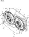
- FIG 1 12 shows a schematic perspective view of a device 10 embodied, for example, as a crushing machine, which has a support device 12 that is also referred to as a torque support or that functions as a torque support.
- a support device 12 that is also referred to as a torque support or that functions as a torque support.
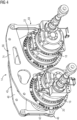
- 3 and 4 show another device 14, whereby the previous and following statements on device 10 also apply to device 14 can be transferred and vice versa, unless otherwise stated.
- the device 10 or 14 has a first gear 16 and a second gear 18, which are preferably designed as planetary gears and are arranged axially parallel. This means that the gears 16 and 18 are arranged side by side and parallel to one another with respect to their respective axial directions.
- the transmission 16 has a first housing 20 , with the transmission 18 having a second housing 22 .
- the respective transmission 16 and 18 includes respective transmission elements. Since the respective transmission 16 or 18 is preferably designed as a planetary gear, a respective first of the respective transmission elements is designed as a sun gear, with a respective second of the respective transmission elements being designed as a ring gear and a respective third of the respective transmission elements being designed as a planetary carrier.
- At least one planet gear is rotatably mounted on the planet carrier and meshes simultaneously with the respective sun gear and with the respective ring gear.
- the ring gear of the gear 16 is off FIG 1 recognizable and denoted there by 24, the ring gear of the transmission 18 in FIG 1 recognizable and is denoted by 26 there.
- at least one of the respective transmission elements of the transmission 16 can be rotated about a first axis of rotation 28 relative to the housing 20 .
- at least one of the transmission elements of the transmission 18 can be rotated about a second axis of rotation 30 relative to the housing 22 .
- FIG 1 As can be seen, the axes of rotation 28 and 30 are spaced apart from one another because the gears 16 and 18 are arranged axis-parallel to one another, with the axes of rotation 28 and 30 running parallel to one another.
- FIG 1 Also illustrated in FIG 1 an arrow 32, a first direction of rotation, in which one gear element of gear 16 can be rotated about axis of rotation 28 relative to housing 20, or during operation of device 10 or 14 is rotated. Also illustrated in FIG 1 an arrow 34 a second direction of rotation, in which one transmission element of the transmission 18 can be rotated or is rotated about the axis of rotation 30 relative to the housing 22, in particular during operation of the device 10 or 14.
- the directions of rotation and thus the gear elements that can rotate about the axes of rotation 28 and 30 relative to the housings 20 and 22 are in opposite directions or in opposite directions.
- the gear elements of the gears 16 and 18 rotating about the axes of rotation 28 and 30 relative to the housings 20 and 22 rotate in opposite directions or in opposite directions.
- the device 10 or 14 has, for example, a first drive shaft assigned to the transmission 16 , the device 10 or 14 for example having a second drive shaft assigned to the transmission 18 .
- the drive shafts are also referred to as shafts or machine shafts.
- the first drive shaft is rotatable about a first shaft axis relative to the housings 20 and 22, with the first drive shaft having the first direction of rotation. This means that the first drive shaft rotates in the first direction of rotation about the first shaft axis of rotation relative to the housings 20 and 22 during operation of the device 10 or 14 . It is preferably provided that the first axis of rotation of the shaft coincides with the first axis of rotation 28 .
- one transmission element of the transmission 16 is arranged on the first drive shaft.
- one transmission element of the transmission 16 can be connected to the first drive shaft in a torque-proof manner.
- drive power can be introduced into the first transmission 16 via the first drive shaft, as a result of which the first transmission 16 can be driven or, in particular during operation of the device 10 or 14, can be driven.
- the second drive shaft is rotatable about a second shaft axis of rotation relative to the housings 20 and 22, the second drive shaft having the second direction of rotation.
- the second drive shaft rotates about the second shaft axis of rotation in the second direction of rotation relative to the housings 20 and 22.
- the second shaft axis of rotation coincides with the second axis of rotation 30.
- one transmission element of the transmission 18 is arranged on the second drive shaft and/or one transmission element of the transmission 18 is non-rotatably connected to the second drive shaft.
- drive power can be introduced into the transmission 18 via the second drive shaft, as a result of which the transmission can be driven or is driven during operation of the device 10 or 14 .
- the drive shafts rotate in opposite directions or in opposite directions during operation.
- the gear 16 is slipped onto the first drive shaft, in particular in such a way that one gear element of the gear 16 is slipped onto the first drive shaft.
- the gear 18 is slipped onto the second drive shaft, in particular in such a way that one gear element of the gear 18 is slipped onto the second drive shaft.
- the axes of rotation of the shafts are spaced apart from one another, with the axes of rotation of the shafts preferably running parallel to one another.
- FIG 1 illustrated by arrows x, y and z directions.
- the direction illustrated by arrow x and the direction illustrated by arrow y are perpendicular to each other, with the direction illustrated by arrow z being perpendicular to the direction illustrated by arrow x and perpendicular to the direction illustrated by arrow y.
- the direction illustrated by the arrow y runs in the axial direction of the transmission 18 and thus along the axis of rotation 28. This means that the axis of rotation 28 along the axial direction of the transmission 16, and the axis of rotation 30 runs along the axial direction of the transmission 18.
- the ring gear 24 is coupled or connected to the housing 20 in a torque-transmitting manner, in particular in a torque-proof manner. It is also conceivable that the ring gear 26 is connected or coupled to the housing 22 in a torque-transmitting manner, in particular in a torque-proof manner.
- ring gear 24 may be integral with housing 20
- ring gear 26 may be integral with housing 22 .
- the ring gear 24 and the housing 20 are designed as components that are designed separately from one another and are connected to one another in a torque-proof manner.
- the ring gear 26 can be formed in one piece with the housing 22, or the ring gear 26 and the housing 22 are formed as components which are formed separately from one another and are connected to one another, in particular in a rotationally fixed manner.
- the support device 12 now has a first support flange 36, also referred to as a first flange, which is connected to the housing 20 in a torque-transmitting manner, in particular in a torque-proof manner.
- first flange 36 also referred to as a first flange
- the housing 20 and the support flange 36 are formed as separately formed and non-rotatably connected components.
- the support device 12 also has a second support flange 38 which is preferably formed separately from the support flange 36 .
- the second support flange 38 is connected to the second housing 22 in a torque-transmitting manner, in particular in a torque-proof manner.
- the support flange 38 and the housing 22 are designed as components which are designed separately from one another and are connected to one another, in particular in a rotationally fixed manner. In this way, for example, torques or reaction torques can be transmitted from the ring gear 24 via the housing 20 to the support flange 36, and torques or reaction torques can be transmitted from the ring gear 26 to the support flange 38 via the housing 22 .
- the support device 12 also has a first support 40 via which a support force can be transmitted from the first support flange 36 to the second support flange 38 .
- This supporting force results, for example, from the respective torque or reaction torque, which is transmitted from ring gear 24 via housing 20 to supporting flange 36 .
- the respective torque or reaction torque can be transmitted from ring gear 24 via housing 20 to support flange 36 and from support flange 36 via support 40 to support flange 38, whereby, for example, the torque or reaction torque is supported and rotation of the ring gear 24 can be limited or avoided.
- the support 40 has a first lever element 42, also referred to as a first strut or first strut element, which is coupled by means of exactly one first joint 44 in an articulated manner to a first connection element 46 provided on the first support flange 36 and is thus articulated to the first support flange 36.
- the first connection element 46 and the first support flange 36 are, for example, components which are formed separately from one another and are connected to one another, in particular in a torque-transmitting or non-rotatable manner.
- the first connection element 46 is also referred to as the first ear, since the first connection element 46 protrudes in the radial direction of the first transmission 16 from the first support flange 36, in particular outwards.
- the first support 40 also has a support element 48 which is coupled in an articulated manner to the first lever element 42 by means of exactly one second joint 50 .
- the first support element 48 is connected to the second support flange 38 in a torque-transmitting manner, in particular in a torque-proof manner.
- connection element 46 has two connection parts 52 and 54 which are spaced apart from one another in the axial direction of the transmission 16 and thus along the axis of rotation 28 and which can be formed in one piece with one another. Furthermore, it is conceivable that the connection parts 52 and 54 are designed as components which are designed separately from one another and are connected to one another, in particular via the support flange 36 . Since the connection element 46 is connected to the support flange 36 in a torque-proof manner, the connection parts 52 and 54 are also connected to the support flange 36 in a torque-proof manner.
- the connection parts 52 and 54 are formed as metal sheets, ie as sheet metal components.
- the support element 48 has two support parts 56 and 58 which are spaced apart from one another in the axial direction of the first transmission 16 and which in each case partially form the joint 50 .
- the connection parts 52 and 54 each partially form the joint 44 .
- the first lever element 42 is partially arranged between the connection parts 52 and 54 and is coupled in an articulated manner to the connection element 46 via the connection parts 52 and 54 .
- the lever member 42 is partially disposed between the support members 56 and 58 and is pivotally coupled to the support member 48 via the support members 56 and 58 .
- the connection parts 52 and 54 are also referred to as first connection parts, with the support parts 56 and 58 also being referred to as first support parts.
- the second support flange 38 is arranged in the axial direction of the second transmission 18 between the support parts 56 and 58, which are each connected to the support flange 38 in a torque-transmitting, in particular non-rotatable manner.
- the support part 56 is arranged on a first side 60 of the support flange 38 and on the side 60 torque-transmitting, in particular non-rotatably connected to the support flange 38.
- the support part 58 is preferably arranged on a second side 62 of the support flange 38 facing away from the first side 60 of the support flange 38 in the axial direction of the second transmission 18 and is connected to the support flange 38 in a torque-transmitting manner, in particular non-rotatably, on the second side 62.
- a double-shear, articulated connection of the support element 48 to the lever element 42 and a double-shear, non-rotatable connection of the support element 48 to the support flange 38 are represented. In this way, for example, excessive bending stresses on the support flange 38, which is particularly subjected to tensile loads, can be avoided.
- the support flange 38 is subjected to tension, in particular exclusively to tension, via the support 40 because the torque or reaction torque is transmitted from the transmission 16 via the support 40 to the support flange 38 .
- tension in particular exclusively to tension
- the lever element 42 is formed in one piece.
- the respective support flange 36 or 28 is designed as a cast component.
- the first support element 48 in FIG 1 arranged at least predominantly, in particular completely, below the support flanges 36 and 38 in the vertical direction illustrated by a double arrow 64 .
- the support device 12 has a second support 66, via which a second support force can be transmitted from the second support flange 38 to the first support flange 36, in particular during operation of the device 10 or 14 Device 10 or 14 from the ring gear 26 via the Housing 22 are transferred to the support flange 38 and from the support flange 38 via the second support 66 to the support flange 36, whereby a rotation of the ring gear 26 or the housing 22 is at least limited or prevented.
- the second support 66 has a second lever element 68, also referred to as a second strut or second strut element, which is coupled in an articulated manner by means of exactly one third joint 70 to a second connection element 72 provided on the second support flange 38 and is thus articulated to the second support flange 38.
- the connection element 72 is designed in one piece.
- the connection element 72 and the support flange 38 are designed as components which are designed separately from one another and are connected to one another in a torque-transmitting, in particular non-rotatable manner.
- the connection element 72 is arranged on the side 60 and is connected to the support flange 38 in a rotationally fixed manner on the side 60 .
- the second support 66 comprises a second support element 74, which in the case of FIG FIG 1 shown embodiment is formed in one piece.
- the second support element 74 is connected in an articulated manner to the second lever element 68 by means of exactly one fourth joint 76, so that the lever element 68 can pivot or rotate relative to the connection element 72 and relative to the support element 74 within certain limits.
- the second support element 74 is connected to the support flange 36 in a torque-transmitting manner, in particular in a torque-proof manner.
- the support element 74 is arranged on a first side 78 of the support flange 36 and is connected to the support flange 36 on the side 78 in a torque-transmitting manner, in particular in a torque-proof manner.
- Sides 60 and 78 point in the same direction.
- the sides 60 and 78 are arranged in a common plane or in the same plane, which runs, for example, perpendicularly to the respective axis of rotation 28 or 30, respectively.
- the second support element 74 is arranged at least predominantly, in particular completely, above the support flanges 36 and 38 in the vertical direction.
- the space required for the support device 12 can be kept within a particularly small framework.
- a particularly advantageous transmission of torque or force and, in particular, the introduction of torque or force can be implemented, so that the support device 12 can be configured in a particularly filigree manner and thus in a manner that is economical in terms of cost, installation space and weight.
- a particularly homogeneous introduction of tensile loads in particular into the support flange 38 designed as a cast flange, can be implemented.
- the second lever element 68 has two first lever parts 80 and 82 which are spaced apart from one another in the axial direction of the transmission 18 and which in each case partially form the joint 76 .
- the support element 74 is arranged between the lever parts 80 and 82 and is connected in an articulated manner to the lever element 68 via the lever parts 80 and 82 .
- the lever element 68 has two second lever parts 84 and 86 which are spaced apart from one another in the axial direction of the transmission 18 and between which the connecting element 72 , which is preferably designed in one piece, is arranged.
- the connection element 72 is connected in an articulated manner to the second lever element 68 via the second lever parts 84 and 86 .
- the connection element 72 is also referred to as the second ear, since it protrudes from the support flange 38 in the radial direction of the transmission 18, in particular outwards.
- the lever parts 80 and 84 are preferably formed by a one-piece, first component 88, with the lever parts 82 and 86 preferably being formed by a one-piece, second component 90.
- Components 88 and 90 are designed as separate, interconnected, and in axial direction of the transmission 18 spaced components formed.
- the respective component 88 or 90 is designed as a sheet metal part or sheet metal component.
- the respective support part 56 or 58 is designed as a sheet metal part or sheet metal component.
- the support flange 38 is arranged in the axial direction of the transmission 18 between the respective support regions 92 and 94 of the support element 48, with the support region 92 being formed in one piece with the support part 56 and the support region 94 being formed in one piece with the support part 58.
- the support element 48 is thus configured to transmit torque via the support regions 92 and 94 , in particular in a rotationally fixed manner, with the support flange 38 .
- support part 56 forms support area 92
- support part 58 forms support area 94.
- the support element 74 is designed like the support element 48, the connection element 72 like the connection element 46 and the lever element 68 like the lever element 42, whereby a particularly low-load operation can be realized.
- FIG 2 shows the device 10 according to FIG FIG 1 in a schematic side view.
- the torque-transmitting, in particular non-rotatable, connection of the support element 74 to the support flange 36 can be seen particularly well.
- the support element 74 and the support flange 36 are connected to one another in a torque-transmitting manner via respective connecting surfaces 96 , also referred to as connection surfaces, and are supported on one another, in particular directly, in the axial direction of the transmission 16 .
- a force arrow F illustrates a force which can occur during operation of the device 10, for example. So it's over FIG 2 an eccentric application of force, in particular of the support element 74 on the support flange 36, can be seen particularly well.
- the support element 48--as described above-- is connected in a rotationally fixed manner to the support flange 38 both on the side 60 and on the side 62 facing away from the side 60, a particularly homogeneous or homogenized load introduction into the support flange 38 can be realized. This can also be transferred to the support flange 36 .
- the support element 74 is arranged on a side 98 of the support flange 36 facing away from the side 78 of the support flange 36 in the axial direction of the transmission 16 and is connected to the support flange 36 in a torque-proof manner on the side 98 .
- the support element 74 also has second support parts which are spaced apart from one another in the axial direction of the transmission 16 or 18 and between which, for example, the support flange 36 is arranged.
- support element 74 has the second support parts, which form second support areas that are spaced apart from one another in the axial direction of transmission 16 or are formed in one piece with the second support areas, with support flange 36—like support flange 38—between support parts 56 and 58 or between the support areas 92 and 94 - is arranged between the second support areas or between the second support parts of the support element 74 .
- one of the second support parts is arranged on the side 78 and is non-rotatably connected to the support flange 36 on the side 78 .
- the second of the second support parts is arranged on the side 98 and is non-rotatably connected to the support flange 36 on the side 98 .
- both support elements 48 and 74 are integrally formed or in the device 14 according to 3 the support element 48 is designed like the support element 74 .
- Arrows indicate respective forces which can occur during operation of the device 14 and are transmitted accordingly.
- the supports 40 and 66 each generate a counter-torque to the respective transmission 18 or 16, which is also referred to as a sister transmission, so that the support device 12, which is also referred to as a supporting structure or functions as a supporting structure, only has slight torque fluctuations and the respective weight of the respective transmission 16 or 18 must record.
- the drive shafts it is conceivable for the drive shafts to be displaceable relative to one another in the axial direction and/or in the radial direction.
- the support 40 in the vertical direction below the support flanges 36 and 38 and the support 66 in the vertical direction above the support flanges 36 and 38 .
- the device 14 according to FIG FIG 4 provided that both supports 40 and 66 are arranged in the vertical direction above the support flanges 36 and 38.
- the strut forces acting on the support elements 48 and 74 and on the ears act counter to the direction of rotation for torque compensation. This results in comparison to the in FIG 4 standard support illustrated the special feature that one of the struts is not subjected to tension but to pressure. This compressive load at the end of the respective support 40 or 66 then leads, for example, to a tensile load on the FIG 1 support flange 38 shown on the right.
- the support flanges 36 and 38 are preferably designed as cast components and are therefore formed from a cast material.
- cast materials react sensitively to tensile stress and the resulting tensile stress, it can now be disadvantageous that tensile stress generally occurs and the tensile stress - as in FIG 2 is illustrated - via a lever arm resulting from the eccentric introduction of force, especially half the column width, can cause additional bending stress.
- the supporting device 12 can be designed to be particularly solid and thus expensive and heavy.
- the support device 12 can be made filigree and thus lighter in weight and cost.
- the supports 40 and 66 can be arranged in a manner that is favorable in terms of installation space, with the support 66 being arranged above and the support 40 being arranged below the support flanges 36 and 38 .
- an at least essentially homogeneous load introduction into the support 40 or 66 that is loaded in compression can be realized by the two-part configuration and connection.
- the lower support 40 in particular the lower support element 48, has a double-shear design.
- the respective support part 56 or 58 preferably has a first width running in the axial direction of the respective transmission 16 or 18, with the support element 74, for example, having a second width running in the axial direction of the transmission 16 or 18.
- the first width is half the second width.
- the respective connection part 52 or 54 has a third width running in the axial direction of the transmission 16 or 18, with the connection element 72 being a third width in the axial direction of the transmission 16 or 18 running fourth width.
- the third width is preferably half the fourth width.
- the lever element 42 no longer runs outside of the support element 48 and the connection element 46, but rather between the connection parts 52 and 54 and between the support parts 56 and 58.
- the lever element 68 is formed as a welded assembly.
- a compressive force from the lever element 42 can, for example, be transmitted at least essentially homogeneously via the joint 50 to the two support parts 56 and 58 designed as support halves. This load introduction leads to mutually canceling bending moments at the support flange 38, as a result of which excessive bending stresses and excessive bending stresses in the support flange 38 can be avoided.
- the double-shear nature of the support element 48 on the support flange 38 also means that, compared to the upper support 66, twice as much force is transmitted via friction as with a single-shear connection, which is the case with the support 66 with regard to the connection of the support element 74 to the support flange 36 and/or the lever element 68 is provided. Screws that are used and are designed, for example, as fitting screws, by means of which, for example, the respective support element 48 or 74 is connected in a rotationally fixed manner to the respective support flange 36 or 38 are additionally relieved by the connection described.
- the upper support 66 can also be designed in two sections like the lower support 40. If the upper support 66, in particular the support element 74, as in FIG 1 embodied in one piece or in one piece as shown, the support element 74 can be arranged and fastened on the side 78 designed as the front side, for example, or on the side 98 designed as the rear side.
- the support device 12 also referred to as a support, includes the one on top Support 66 and underlying support 40 which includes support members 56 and 58.
- a respective counter-torque can be introduced via the respective ear attached to the respective support flange 36 or 38 into the opposite gear 18 or 16 in each case.
- the lower lever element 42 runs in part between the support parts 56 and 58, which are preferably embodied symmetrically, in particular mirror-symmetrically.
- the lever element 42 runs partially between the connection parts 52 and 54, which are preferably formed symmetrically, in particular mirror-symmetrically.
Landscapes
- Engineering & Computer Science (AREA)
- General Engineering & Computer Science (AREA)
- Mechanical Engineering (AREA)
- Food Science & Technology (AREA)
- General Details Of Gearings (AREA)
- Pivots And Pivotal Connections (AREA)
- Devices For Conveying Motion By Means Of Endless Flexible Members (AREA)
Description
- Die Erfindung betrifft eine Stützvorrichtung für zwei Getriebe gemäß dem Oberbegriff von Patentanspruch 1. Ferner betrifft die Erfindung eine Vorrichtung mit einer solchen Stützvorrichtung gemäß dem Oberbegriff von Patentanspruch 11.
- Die
EP 0 775 525 A1 offenbart eine Drehmomentabstützung für zwei gegenläufig angetriebene Walzen, von denen eine fest und die andere gegenüber der festen Walze verschiebbar in einem Maschinenrahmen angeordnet ist. Die Walzen sind auf der gleichen Walzenseite mit jeweils einem Walzenzapfen versehen, auf den ein Getriebe aufgesteckt ist. Mit den Getrieben sind Drehmomentstützen fest verbunden, denen jeweils zwei Anlenkpunkten durch Koppelstangen gelenkig miteinander verbunden sind. Dabei ist es vorgesehen, dass alle Anlenkpunkte der Koppelstangen auf einer Seite einer durch die Achsen der Walzen verlaufenden Mittelebene angeordnet sind. - Außerdem ist der
EP 0 992 710 A2 eine doppelseitige Drehmomentstütze für ein auf die Maschinenwelle einer Arbeitsmaschine aufgestecktes Getriebe als bekannt zu entnehmen. - Aus der
WO 2017/091684 A1 ist eine Anordnung der eingangs definierten Art bekannt, die eine "einfache" Abstützung vorsieht, die nicht das Biegemoment in dem Stützflansch reduziert. - Aufgabe der vorliegenden Erfindung ist es, eine Stützvorrichtung und eine Vorrichtung mit einer solchen Stützvorrichtung zu schaffen, sodass ein besonders belastungsarmer Betrieb realisiert werden kann.
- Diese Aufgabe wird erfindungsgemäß durch eine Stützvorrichtung mit den Merkmalen des Patentanspruchs 1 sowie durch eine Vorrichtung mit den Merkmalen des Patentanspruchs 11 gelöst. Vorteilhafte Ausgestaltungen mit zweckmäßigen Weiterbildungen der Erfindung sind in den übrigen Ansprüchen angegeben.
- Ein erster Aspekt der Erfindung betrifft eine Stützvorrichtung für, insbesondere wenigstens oder genau, zwei Getriebe und somit beispielsweise für ein Getriebepaar, welches durch die Getriebe gebildet ist. Die beispielsweise auch als Drehmomentstütze bezeichnete oder als Drehmomentstütze fungierende Stützvorrichtung weist einen ersten Stützflansch auf, welcher mit einem ersten der Getriebe, insbesondere drehmomentübertragend, koppelbar ist. Insbesondere ist beispielsweise der erste Stützflansch mit einem ersten Gehäuse des ersten Getriebes, insbesondere drehmomentübertragend, koppelbar. Insbesondere ist es denkbar, dass der erste Stützflansch mit dem ersten Getriebe, insbesondere mit dem ersten Gehäuse des ersten Getriebes, drehfest koppelbar beziehungsweise gekoppelt ist. Wieder mit anderen Worten ausgedrückt kann beispielsweise der erste Stützflansch mit dem ersten Getriebe, insbesondere mit dem ersten Gehäuse des ersten Getriebes, fest beziehungsweise starr verbindbar oder verbunden sein.
- Die Stützvorrichtung weist darüber hinaus einen zweiten Stützflansch auf, welcher mit dem zweiten Getriebe, insbesondere drehmomentübertragend, koppelbar ist. Insbesondere ist es denkbar, dass der zweite Stützflansch mit einem zweiten Gehäuse des zweiten Getriebes, insbesondere drehmomentübertragend, koppelbar ist. Hierbei kann insbesondere vorgesehen sein, dass der zweite Stützflansch drehfest mit dem zweiten Getriebe, insbesondere mit dem zweiten Gehäuse, koppelbar oder gekoppelt ist. Wieder mit anderen Worten ausgedrückt kann beispielsweise der zweite Stützflansch mit dem zweiten Getriebe, insbesondere mit dem zweiten Gehäuse, starr beziehungsweise fest koppelbar oder gekoppelt sein. Durch die insbesondere drehmomentübertragende Koppelbarkeit beziehungsweise Kopplung des jeweiligen Stützflanschs mit dem jeweiligen Getriebe kann beispielsweise ein Drehmoment oder ein aus einem Drehmoment resultierendes Reaktionsmoment vor dem jewei3ligen Getriebe, insbesondere vor dem jeweiligen Gehäuse, auf den jeweiligen Stützflansch übertragen und über den jeweiligen Stützflansch abgestützt werden, insbesondere derart, dass das jeweilige Gehäuse abgestützt und dadurch gegen eine Drehung gesichert wird. Hierdurch ist es insbesondere möglich, ein jeweiliges, beispielsweise drehfest mit dem jeweiligen Gehäuse verbundenes Getriebeelement des jeweiligen Getriebes abzustützen und somit gegen eine Drehung zu sichern.
- Die Stützvorrichtung weist dabei wenigstens eine Stütze auf, über welche eine Stützkraft von dem ersten Stützflansch auf den zweiten Stützflansch übertragbar ist. Dies bedeutet beispielsweise im Hinblick auf das zuvor genannte Drehmoment beziehungsweise Reaktionsmoment, dass das Drehmoment beziehungsweise Reaktionsmoment beispielsweise von dem ersten Gehäuse auf den ersten Stützflansch und von dem ersten Stützflansch über die Stütze auf den zweiten Stützflansch übertragen und hierdurch abgestützt werden kann. Die wenigstens eine Stütze weist dabei ein auch als Strebe oder Strebenelement bezeichnetes Hebelelement auf, welches gelenkig mit einem an dem ersten Stützflansch vorgesehenen Anbindungselement und dadurch gelenkig mit dem ersten Stützflansch gekoppelt ist. Insbesondere ist es vorgesehen, dass das Hebelelement mittels, insbesondere genau, eines Gelenks gelenkig mit dem Anbindungselement und mit dem ersten Stützflansch gekoppelt ist. Das Anbindungselement ist beispielsweise ein sogenanntes Ohr, welches beispielweise von dem Stützflansch an sich absteht, insbesondere in radialer Richtung des ersten Getriebes.
- Grundsätzlich ist es denkbar, dass das Anbindungselement einstückig mit dem ersten Stützflansch ausgebildet ist, oder das Anbindungselement und der erste Stützflansch sind separat voneinander ausgebildete und, insbesondere drehfest, miteinander verbundene Bauteile.
- Die wenigstens eine Stütze weist darüber hinaus ein gelenkig mit dem Hebelelement gekoppeltes Stützelement, welches beispielsweise mittels, insbesondere genau, eines zweiten Gelenks gelenkig mit dem Hebelelement gekoppelt ist. Außerdem ist das Stützelement mit dem zweiten Stützflansch verbunden. Insbesondere ist das Stützelement drehmomentübertragend, insbesondere drehfest, mit dem zweiten Stützflansch verbunden. Hierdurch kann beispielsweise das Dreh- beziehungsweise Reaktionsmoment von dem ersten Gehäuse auf den ersten Stützflansch, von dem ersten Stützflansch über das Anbindungselement auf das Hebelelement, von dem Hebelelement auf das Stützelement und von dem Stützelement auf den zweiten Stützflansch übertragen und hierdurch abgestützt werden. Vorzugsweise ist das Hebelelement separat von dem Anbindungselement, separat von den Stützflanschen und separat von dem Stützelement ausgebildet, wobei die Stützflansche auch als Flansche bezeichnet werden. Ferner kann das Stützelement separat von dem Hebelelement und separat von den Stützflanschen ausgebildet sein.
- Um nun einen besonders belastungsarmen Betrieb der Stützvorrichtung realisieren zu können, ist es erfindungsgemäß vorgesehen, dass das Anbindungselement zwei, insbesondere in axialer Richtung des ersten Getriebes, voneinander beabstandete Anbindungsteile aufweist. Die Anbindungsteile können einstückig miteinander ausgebildet sein, oder die Anbindungsteile sind als separat voneinander ausgebildete und, insbesondere über den ersten Stützflansch, miteinander verbundene Bauteile ausgebildet.
- Des Weiteren ist es erfindungsgemäß vorgesehen, dass das Stützelement zwei, insbesondere in axialer Richtung des ersten Getriebes, voneinander beabstandete Stützteile aufweist. Die Stützteile können einstückig miteinander ausgebildet sein, oder die Stützteile können als separat voneinander ausgebildete und, insbesondere über den zweiten Stützflansch, miteinander verbundene Bauteile ausgebildet sein. Außerdem ist es erfindungsgemäß vorgesehen, dass das Hebelelement teilweise zwischen den Anbindungsteilen und teilweise zwischen den Stützteilen angeordnet ist. Das Hebelelement ist dabei über die Anbindungsteile gelenkig mit dem Anbindungselement und somit mit dem ersten Stützflansch gekoppelt. Außerdem ist das Hebelelement über die Stützteile gelenkig mit dem Stützelement gekoppelt. Dadurch, dass das Stützelement die voneinander beabstandeten Stützteile aufweist, ist das Stützelement zweischnittig ausgeführt. Hierdurch kann ein besonders belastungsarmer Betrieb realisiert werden. Der Erfindung liegen dabei insbesondere die folgenden Erkenntnisse zugrunde:
Aus Bauraum- und somit Platzgründen kann es wünschenswert sein, die Stützflansche und insbesondere die Stütze derart anzuordnen, dass das Hebelelement nicht auf Zug, sondern auf Druck beansprucht wird. Dies kann zu einer Druckbelastung an einem dem zweiten Stützflansch zugewandten beziehungsweise zugeordneten Ende der Stütze führen, was wiederum zu einer Zugbelastung des zweiten Stützflanschs führen kann. Eine solche Zugbelastung und daraus resultierende Zugspannungen des jeweiligen Stützflansches können unerwünscht beziehungsweise ungünstig sein und insbesondere zu einer zusätzlichen Biegebeanspruchung des jeweiligen Stützflansches führen. In der Folge müsste der jeweilige Stützflansch aus einem besonders festen, insbesondere höherfesten Material hergestellt werden, was zu unerwünscht hohen Kosten der Stützvorrichtung führen kann. Ferner ist es denkbar, den jeweiligen Stützflansch besonders groß beziehungsweise massiv zu dimensionieren, was jedoch zu einem unerwünscht hohen Gewicht und zu einem unerwünscht hohen Bauraumbedarf der Stützvorrichtung führen kann. - Durch die beschriebene, zweischnittige Ausführung des Stützelements können nun übermäßige Belastungen insbesondere des zweiten Stützflansches vermieden werden, sodass der jeweilige Stützflansch beziehungsweise die Stützvorrichtung insgesamt besonders filigran und somit gewichts-, kosten- und bauraumgünstig ausgestaltet werden kann. Insbesondere kann eine solche Lasteinleitung, insbesondere in den zweiten Stützflansch, realisiert werden, sodass es zu sich gegenseitig aufhebenden Biegemomenten kommt. Dadurch können unerwünschte und übermäßige Biegespannungen in dem zweiten Stützflansch vermieden werden. Die Zweischnittigkeit, insbesondere an dem zweiten Stützflansch, führt zudem dazu, dass beispielsweise im Vergleich zu einer einschnittigen Ausgestaltung des Stützelements doppelt so viel Kraft über Reibung übertragen werden kann. Dadurch können beispielswiese zum Einsatz kommende Schrauben, insbesondere Passschrauben, entlastet werden, sodass die Stützvorrichtung besonders filigran ausgestaltet werden kann.
- Da das Stützelement die zwei voneinander beabstandeten Stützteile aufweist, zwischen welchen das Hebelelement angeordnet ist, und dadurch, dass das Hebelelement über die voneinander beabstandeten Stützteile gelenkig mit dem Stützelement gekoppelt ist, ist eine zweischnittige, gelenkige Anbindung des Stützelements an das Hebelelement realisiert. Diese zweischnittige Anbindung kann vorzugsweise auch auf den zweiten Stützflansch übertragen werden. Dabei ist es vorzugsweise vorgesehen, dass das Stützelement zwei, insbesondere in axialer Richtung, des zweiten Getriebes, voneinander beabstandete Stützbereiche aufweist, zwischen welchen der zweite Stützflansch angeordnet ist, wobei der zweite Stützflansch über die Stützbereiche mit dem Stützelement, insbesondere drehmomentübertragend beziehungsweise drehfest, verbunden ist. Hierdurch ist auch eine zweischnittige, jedoch vorzugsweise feste beziehungsweise drehfeste, Anbindung des Stützelements an den zweiten Stützflansch vorgesehen, sodass übermäßige, unerwünschte Biegebelastungen des zweiten Stützflansches vermieden werden können. Dabei ist es denkbar, dass die Stützbereiche einstückig miteinander ausgebildet sind, oder die Stützbereiche sind als separat voneinander ausgebildete und, insbesondere über den zweiten Stützflansch, miteinander verbundene Bauteile ausgebildet. Insbesondere ist es denkbar, dass ein erstes der Stützteile und ein erster der Stützbereiche einstückig miteinander ausgebildet und somit beispielsweise durch eine einstückige erste Komponente gebildet sind, wobei beispielsweise das zweite Stützteil und der zweite Stützbereich einstückig miteinander ausgebildet und somit beispielsweise durch eine einstückige zweite Komponente gebildet sind. Die Komponenten sind dabei separat voneinander ausgebildet und, insbesondere über den zweiten Stützflansch und/oder über das Hebelelement, miteinander verbundene Bauteile ausgebildet. Insbesondere kann die jeweilige Komponente aus einem Blech gebildet und somit beispielsweise als ein Blech beziehungsweise als ein Blechbauteil ausgebildet sein. Alternativ oder zusätzlich ist es denkbar, dass das jeweilige Anbindungsteil aus einem Blech gebildet und somit als ein Blech oder als ein Blechbauteil ausgebildet ist.
- Vorzugsweise ist das erste Stützelement über die insbesondere in axialer Richtung des zweiten Getriebes voneinander beabstandeten Stützbereiche, insbesondere drehmomentübertragend beziehungsweise drehfest, mit dem zweiten Stützflansch verbunden, welcher zwischen den Stützbereichen angeordnet sein kann.
- Insgesamt ist erkennbar, dass sich durch die zweischnittige Ausgestaltung des Stützelements eine besonders vorteilhafte Abstützung mit einem besonders vorteilhaften Kraftangriff an dem Stützelement realisieren lässt, insbesondere derart, dass eine übermäßige Biegebelastung vermieden werden kann.
- Insbesondere ist es denkbar, dass die Komponenten symmetrisch ausgestaltet sind, wobei es alternativ oder zusätzlich vorgesehen sein kann, dass die Anbindungsteile symmetrisch zueinander ausgebildet sind. Insbesondere kann eine zumindest nahezu biegemomentfreie Lasteinleitung in die Stütze und den korrespondierenden, zweiten Stützflansch realisiert werden, sodass eine übermäßige Belastung des insbesondere auf Zug belasteten zweiten Stützflanschs vermieden werden kann. In der Folge kann eine unerwünschte Überdimensionierung der Stützvorrichtung vermieden werden. Außerdem kann das Hebelelement als besonders einfache und somit gewichts- und kostengünstige Strebenkonstruktion ausgeführt werden. Des Weiteren können jeweilige Wanddicken, insbesondere Blechstärken, der Komponenten gering gehalten werden, sodass das Gewicht der Stütze besonders gering gehalten werden kann. Außerdem können besonders hohe Bearbeitungsgeschwindigkeiten bei einem Ausbrennen realisiert werden. Des Weiteren kann eine zweischnittige Belastung der zuvor genannten Schrauben, insbesondere Passschrauben, realisiert werden, sodass zum Einsatz kommendes Material besonders gut ausgenutzt werden kann. Unter der jeweiligen, zweischnittigen Anbindung beziehungsweise Belastung ist insbesondere zu verstehen, dass die Stütze an das Hebelelement beziehungsweise an den zweiten Stützflansch über wenigstens oder genau zwei Trennfugen angebunden ist. Außerdem kann unter der zweischnittigen Belastung der Schrauben verstanden werden, dass die Schrauben durch beziehungsweise über zwei Trennfugen belastet werden, wodurch die Belastung der Schrauben besonders gering gehalten werden kann.
- Um die Kosten und das Gewicht der Stützvorrichtung besonders geringhalten zu können, ist es in einer Ausgestaltung der Erfindung vorgesehen, dass das Hebelelement einstückig ausgebildet ist.
- Eine weitere Ausführungsform zeichnet sich dadurch aus, dass der jeweilige Stützflansch als ein Gussbauteil ausgebildet ist. Dabei kann der jeweilige Stützflansch insbesondere aus Gusseisen gebildet sein. Hierdurch können die Kosten der Stützvorrichtung besonders gering gehalten werden. Außerdem kann eine übermäßige Belastung, insbesondere des auf Zug belasteten zweiten Stützflansches, vermieden werden.
- Bei einer besonders vorteilhaften Ausführungsform der Erfindung ist in Einbaulage der Stützvorrichtung das Stützelement in vertikaler Richtung zumindest überwiegend, insbesondere vollständig, unterhalb der Stützflansche angeordnet. Die Stützvorrichtung nimmt dabei ihre Einbaulage in vollständig hergestelltem Zustand einer beispielsweise als Anlage, Maschine oder Gerät ausgebildeten Vorrichtung ein, welche in ihrem vollständig hergestellten Zustand die Stützvorrichtung und die Getriebe aufweist. Die Einbaulage der Stützvorrichtung und somit der Vorrichtung ist dabei eine zur bestimmungsgemäßen Nutzung der Vorrichtung und insbesondere der Stützvorrichtung vorgesehene Lage beziehungsweise Ausrichtung der Vorrichtung und somit der Stützvorrichtung, insbesondere im Raum. Dadurch, dass das Stützelement bezogen auf die Einbaulage in vertikaler Richtung zumindest überwiegend, insbesondere vollständig, unterhalb der Stützflansche angeordnet ist, kann der Bauraumbedarf der Stützvorrichtung besonders gering gehalten werden. Unter dem Merkmal, dass das Stützelement in Einbaulage der Stützvorrichtung zumindest überwiegend unterhalb der Stützflansche angeordnet ist, kann insbesondere verstanden werden, dass das Stützelement mehr als zur Hälfte seines Volumens beziehungsweise seiner außenumfangsseitigen Form unterhalb der Stützflansche angeordnet ist.
- Um einen besonders vorteilhaften sowie bauraumgünstigen Betrieb zu realisieren, ist es in weiterer Ausgestaltung der Erfindung vorgesehen, dass die Stützvorrichtung eine zweite Stütze aufweist, über welche eine zweite Stützkraft von dem zweiten Stützflansch auf den ersten Stützflansch übertragbar ist. Hierdurch kann beispielsweise ein Dreh- beziehungsweise Reaktionsmoment von dem zweiten Getriebe, insbesondere von dem zweiten Gehäuse des zweiten Getriebes, über den zweiten Stützflansch auf die zweite Stütze und von der zweiten Stütze auf den ersten Stützflansch übertragen werden, wodurch das zweite Gehäuse abgestützt und insbesondere gegen eine Drehung gesichert werden kann. Die diesbezüglichen Ausführungen zum ersten Getriebe und zur ersten Stütze können mutatis mutandis auch auf das zweite Getriebe und die zweite Stütze übertragen werden und umgekehrt.
- Die zweite Stütze weist dabei ein auch als zweite Strebe oder zweites Strebenelement bezeichnetes zweites Hebelelement auf, welches gelenkig mit einem an dem zweiten Stützflansch vorgesehenen zweiten Anbindungselement und dadurch gelenkig mit dem zweiten Stützflansch gekoppelt ist. Insbesondre ist beispielsweise das zweite Hebelelement mittels, insbesondere genau, eines dritten Gelenks gelenkig mit dem Anbindungselement und somit mit dem zweiten Stützflansch gekoppelt. Die zweite Stütze weist außerdem ein gelenkig mit dem zweiten Hebelelement gekoppeltes Stützelement auf, welches mit dem ersten Stützflansch, insbesondere drehmomentübertragend und/oder drehfest, verbunden ist. Insbesondere ist beispielsweise das zweite Stützelement mittels, insbesondere genau, eines vierten Gelenks gelenkig mit dem zweiten Hebelelement gekoppelt. Durch Verwendung der zweiten Stütze kann auch das zweite Getriebe besonders vorteilhaft und insbesondere besonders bauraumgünstig abgestützt werden.
- Dabei hat es sich als besonders vorteilhaft gezeigt, wenn in Einbaulage der Stützvorrichtung das zweite Stützelement in vertikaler Richtung zumindest überwiegend, insbesondere vollständig, oberhalb der Stützflansche angeordnet ist. Hierdurch kann der Bauraumbedarf der Stützvorrichtung in einem besonders geringen Rahmen gehalten werden. Unter dem Merkmal, dass in Einbaulage der Stützvorrichtung das zweite Stützelement in vertikaler Richtung zumindest überwiegend oberhalb der Stützflansche angeordnet ist, kann insbesondere verstanden werden, dass das zweite Stützelement in Einbaulage der Stützvorrichtung in vertikaler Richtung mehr als zur Hälfte seines Volumens beziehungsweise seiner außenumfangsseitigen Form oberhalb der Stützflansche angeordnet ist.
- Als besonders vorteilhaft hat es sich gezeigt, wenn das Hebelelement zwei voneinander beabstandete erste Hebelteile aufweist, welche insbesondere in axialer Richtung des zweiten Getriebes voneinander beabstandet sind. Zwischen den ersten Hebelteilen ist das zweite Stützelement angeordnet, welches über die ersten Hebelteile gelenkig mit dem zweiten Hebelelement gekoppelt ist. Das Hebelelement weist darüber hinaus zwei, insbesondere in axialer Richtung des zweiten Getriebes, voneinander beabstandete zweite Hebelteile auf, zwischen welchen das zweite Anbindungselement angeordnet ist. Das zweite Anbindungselement ist über die zweiten Hebelteile gelenkig mit dem zweiten Hebelelement gekoppelt. Hierdurch kann eine besonders vorteilhafte, kostengünstige und belastungsarme Anbindung des zweiten Hebelelements an das zweite Stützelement und an das zweite Anbindungselement gewährleistet werden.
- Die ersten Hebelteile sind beispielsweise einstückig miteinander ausgebildet, wobei es alternativ oder zusätzlich vorgesehen sein kann, dass die zweiten Hebelteile einstückig miteinander ausgebildet sind. Ferner ist es denkbar, dass die ersten Hebelteile als separat voneinander ausgebildete und miteinander verbundene Bauteile ausgebildet sind und/oder die zweiten Hebelteile sind als separat voneinander ausgebildete und miteinander verbundene Bauteile ausgebildet. Insbesondere ist es denkbar, dass ein erstes der ersten Hebelteile und ein erstes der zweiten Hebelteile durch ein erstes, einstückiges Bauelement gebildet sind. Außerdem ist es möglich, dass das zweite der ersten Hebelteile und das zweite der zweiten Hebelteile durch ein einstückiges, zweites Bauelement gebildet sind. Die Bauelemente sind dabei separat voneinander ausgebildet und beispielsweise miteinander verbunden.
- Um die Teileanzahl und somit die Kosten besonders gering halten zu können, ist es in weiterer Ausgestaltung der Erfindung vorgesehen, dass das zweite Stützelement und/oder das zweite Anbindungselement einstückig ausgebildet ist. Grundsätzlich ist es denkbar, dass das zweite Anbindungselement einstückig mit dem zweiten Stützflansch ausgebildet ist. Alternativ dazu ist es denkbar, dass das zweite Anbindungselement und der zweite Stützflansch als separat voneinander ausgebildete und miteinander verbundene Bauelemente ausgebildet sind. Insbesondere ist es denkbar, dass das zweite Anbindungselement von dem zweiten Stützflansch an sich absteht.
- Um einen besonders belastungsarmen Betrieb der Stützvorrichtung insgesamt realisieren und in der Folge die Stützvorrichtung besonders filigran und somit gewichts-, kosten- und bauraumgünstig ausgestalten zu können, ist es bei einer Ausführungsform der Erfindung vorgesehen, dass das zweite Anbindungselement zwei voneinander beabstandete zweite Anbindungsteile aufweist. Die zweiten Anbindungsteile können einstückig miteinander ausgebildet sein, oder die zweiten Anbindungsteile sind als separat voneinander ausgebildete und, insbesondere über den zweiten Stützflansch, miteinander verbundene Bauteile ausgebildet. Ferner ist es bei dieser Ausführungsform möglich, dass das zweite Stützelement zwei voneinander beabstandete zweite Stützteile aufweist. Die zweiten Stützteile können einstückig miteinander ausgebildet sein, oder die zweiten Stützteile sind als separat voneinander ausgebildete und, insbesondere über den zweiten Stützflansch, miteinander verbundene Bauteile ausgebildet. Die zweiten Anbindungsteile können beispielsweise aus Blech gebildet und somit als Blechteile oder Bleche ausgebildet sein. Alternativ oder zusätzlich können die zweiten Stützteile aus einem Blech gebildet und somit als Bleche beziehungsweise Blechbauteile ausgebildet sein.
- Dabei hat es sich als ferner vorteilhaft gezeigt, wenn das zweite Hebelelement teilweise zwischen den zweiten Anbindungsteilen und teilweise zwischen den zweiten Stützteilen angeordnet und über die zweiten Anbindungsteile gelenkig mit dem zweiten Anbindungselement und über die zweiten Stützteile gelenkig mit dem zweiten Stützelement gekoppelt ist. Somit ist vorzugsweise auch im Hinblick auf das zweite Stützelement eine zweischnittige Anbindung des zweiten Stützelements an das zweite Hebelelement und vorzugsweise auch an den ersten Stützflansch vorgesehen, sodass übermäßige Belastungen und insbesondere übermäßige Biegebeanspruchungen des ersten Stützflanschs vermieden werden können. Insbesondere ist es denkbar, dass das zweite Stützelement zwei, insbesondere in axialer Richtung des ersten Getriebes, voneinander beabstandete zweite Stützbereiche aufweist, wobei der erste Stützflansch zwischen den zweiten Stützbereichen angeordnet ist. Dabei ist beispielsweise das zweite Stützelement über die zweiten Stützbereiche, insbesondere drehmomentübertragend beziehungsweise drehfest, mit dem ersten Stützflansch verbunden.
- Einer der zweiten Stützbereiche und eines der zweiten Stützteile können durch ein einstückiges erstes Element gebildet sein, wobei der andere zweite Stützbereich und das andere zweite Stützteil durch ein einstückiges zweites Element gebildet sein können. Die Elemente sind beispielsweise separat voneinander ausgebildete und miteinander verbundene Elemente. Das jeweilige Element kann beispielsweise aus einem Blech gebildet und somit als ein Blech beziehungsweise als ein Blechbauteil ausgebildet sein.
- Um die Teileanzahl und somit die Kosten besonders geringhalten zu können, ist es vorzugsweise vorgesehen, dass das zweite Hebelelement einstückig ausgebildet ist.
- Ein zweiter Aspekt der Erfindung betrifft eine beispielsweise als eine Industrievorrichtung oder Industrieapplikation ausgebildete Vorrichtung, welche beispielsweise eine Maschine, ein Gerät oder eine Anlage sein kann. Insbesondere kann die Vorrichtung eine Getriebevorrichtung sein. Die Vorrichtung weist ein erstes Getriebe auf, in welches über eine erste Drehrichtung aufweisende erste Antriebswelle Antriebsleistung eingeleitet werden kann. Außerdem umfasst die Vorrichtung ein zweites Getriebe, in welches über eine der ersten Drehrichtung entgegengesetzte zweite Drehrichtung aufweisende zweite Antriebswelle Antriebsleistung eingeleitet werden kann. Dies bedeutet, dass die einfach auch als Wellen bezeichneten Antriebswellen gegensinnig rotieren, insbesondere während eines Betriebs der Vorrichtung. Mit anderen Worten sind die auch als Maschinenwellen bezeichneten Wellen zueinander gegenläufig. Beispielsweise ist das erste Getriebe auf der ersten Antriebswelle angeordnet, wobei vorgesehen sein kann, dass das erste Getriebe auf die erste Antriebswelle aufgesteckt ist. Alternativ oder zusätzlich kann das zweite Getriebe auf der zweiten Antriebswelle angeordnet sein, wobei es denkbar ist, dass das zweite Getriebe auf die zweite Antriebswelle aufgesteckt ist. Die Antriebswellen sind beispielsweise, insbesondere entlang ihrer jeweiligen radialen Richtung, voneinander beabstandet und verlaufen parallel zueinander.
- Mit anderen Worten ist beispielsweise die erste Antriebswelle um eine erste Drehachse in die erste Drehrichtung drehbar, wobei die zweite Antriebswelle um eine zweite Drehachse in die zweite Drehrichtung drehbar beziehungsweise antreibbar ist. Vorzugsweise sind die Drehachsen voneinander beabstandet, wobei die Drehachsen vorzugsweise parallel zueinander verlaufen. Somit sind eine achsparallele Anordnung der Antriebswellen und in der Folge vorzugsweise auch eine achsparallele Anordnung der Getriebe vorgesehen. Dabei umfasst die Vorrichtung eine Stützvorrichtung, insbesondere gemäß dem ersten Aspekt der Erfindung. Die Stützvorrichtung ermöglicht dabei eine besonders bauraumgünstige Drehmomentabstützung zumindest eines der Getriebe, insbesondere beider Getriebe. Vorzugsweise ist die Stützvorrichtung als eine Schweißkonstruktion ausgebildet, über welche beispielsweise die Getriebe, insbesondere ihre Gehäuse, miteinander verbunden beziehungsweise gekoppelt sind. Insbesondere ist es vorzugsweise vorgesehen, dass die Getriebe, insbesondere Gehäuse, über die Stützvorrichtung kinematisch miteinander gekoppelt sind.
- Die Stützvorrichtung weist dabei einen mit dem ersten Getriebe, insbesondere drehmomentübertragend, gekoppelten ersten Stützflansch und einen mit dem zweiten Getriebe, insbesondere drehmomentübertragend, gekoppelten zweiten Stützflansch auf. Außerdem weist das Getriebe wenigstens eine Stütze auf, über welche eine Stützkraft von dem ersten Stützflansch auf den zweiten Stützflansch übertragbar ist. Die wenigstens eine Stütze weist ein Hebelelement auf, welches gelenkig mit einem an dem ersten Stützflansch vorgesehenen Anbindungselement und dadurch gelenkig mit dem ersten Stützflansch gekoppelt ist. Des Weiteren weist die wenigstens eine Stütze ein gelenkig mit dem Hebelelement gekoppeltes und mit dem zweiten Stützflansch, insbesondere drehmomentübertragend beziehungsweise drehfest, verbundenes Stützelement auf.
- Um nun einen besonders belastungsarmen Betrieb der Vorrichtung realisieren zu können, ist es bei dem zweiten Aspekt der Erfindung vorgesehen, dass das Anbindungselement zwei, insbesondere in axialer Richtung des ersten Getriebes, voneinander beabstandete Anbindungsteile aufweist. Das Stützelement weist zwei, insbesondere in axialer Richtung des Getriebes, voneinander beabstandete Stützteile auf. Dabei ist das Hebelelement teilweise zwischen den Anbindungsteilen und teilweise zwischen den Stützteilen angeordnet, wobei das Hebelelement über die Anbindungsteile gelenkig mit dem Anbindungselement gekoppelt ist. Außerdem ist das Hebelelement über die Stützteile gelenkig mit dem Stützelement gekoppelt. Vorteile und vorteilhafte Ausgestaltungen des ersten Aspekts der Erfindung sind als Vorteile und vorteilhafte Ausgestaltungen des zweiten Aspekts der Erfindung anzusehen und umgekehrt.
- Als besonders vorteilhaft hat es sich gezeigt, wenn das jeweilige Getriebe als ein Planetengetriebe ausgebildet ist. Das Planetengetriebe weist beispielsweise wenigstens oder genau ein Sonnenrad, wenigstens oder genau ein Hohlrad und wenigstens oder genau einen Planetenträger auf. Außerdem umfasst das Planetengetriebe beispielsweise wenigstens ein oder mehrere Planetenräder. Das Planetenrad ist beispielsweise drehbar an dem Planetenträger gelagert und kämmt gleichzeitig mit dem Sonnenrad und mit dem Hohlrad. Das Sonnenrad, das Hohlrad und der Planetenträger sind jeweilige Getriebeelemente des jeweiligen Planetengetriebes, welches auch als Planetensatz oder Planetenradsatz bezeichnet wird. Insbesondere ist es denkbar, dass das Sonnenrad drehfest mit der jeweiligen Antriebswelle verbunden ist. Alternativ oder zusätzlich ist es denkbar, dass das Hohlrad drehmomentübertragend beziehungsweise drehfest mit dem jeweiligen Gehäuse des jeweiligen Getriebes beziehungsweise mit dem jeweiligen Stützflansch verbunden ist.
- Schließlich hat es sich als besonders vorteilhaft gezeigt, wenn die Vorrichtung als eine Zerkleinerungsmaschine, insbesondere als eine Walzmühle, zum Zerkleinern von Zerkleinerungsgut, insbesondere zum Mahlen von Mahlgut, ausgebildet ist.
- Weitere Vorteile, Merkmale und Einzelheiten der Erfindung ergeben sich aus der nachfolgenden Beschreibung eines bevorzugten Ausführungsbeispiels sowie anhand der Zeichnung. Die vorstehend in der Beschreibung genannten Merkmale und Merkmalskombinationen sowie die nachfolgend in der Figurenbeschreibung genannten und/oder in den Figuren alleine gezeigten Merkmale und Merkmalskombinationen sind nicht nur in der jeweils angegebenen Kombination, sondern auch in anderen Kombinationen oder in Alleinstellung verwendbar, ohne den Rahmen der Erfindung zu verlassen.
- Die Zeichnung zeigt in:
- FIG 1
- ausschnittsweise eine schematische Perspektivansicht einer erfindungsgemäßen Vorrichtung;
- FIG 2
- ausschnittsweise eine schematische Seitenansicht der Vorrichtung;
- FIG 3
- ausschnittsweise eine schematische Perspektivansicht einer weiteren Vorrichtung, wobei
FIG 3 der Erläuterung des Hintergrunds der Erfindung dient; und - FIG 4
- eine schematische Perspektivansicht der weiteren Vorrichtung, wobei
FIG 4 der Erläuterung des Hintergrunds der Erfindung dient. - In den Figuren sind gleiche oder funktionsgleiche Elemente mit gleichen Bezugszeichen versehen.
-
FIG 1 zeigt ausschnittsweise in einer schematischen Perspektivansicht eine beispielsweise als Zerkleinerungsmaschine ausgebildete Vorrichtung 10, welche eine auch als Drehmomentstütze bezeichnete oder als Drehmomentstütze fungierende Stützvorrichtung 12 aufweist.FIG 3 und4 zeigen eine weitere Vorrichtung 14, wobei die vorigen und folgenden Ausführungen zur Vorrichtung 10 ohne weiteres auch auf die Vorrichtung 14 übertragen werden können und umgekehrt, falls nichts Anderweitiges angegeben ist. - Wie aus
FIG 4 erkennbar ist, weist die Vorrichtung 10 beziehungsweise 14 ein erstes Getriebe 16 und ein zweites Getriebe 18 auf, welche vorzugsweise als Planetengetriebe ausgebildet und achsparallel angeordnet sind. Dies bedeutet, dass die Getriebe 16 und 18 hinsichtlich ihrer jeweiligen axialen Richtungen nebeneinander und parallel zueinander angeordnet sind. Das Getriebe 16 weist ein erstes Gehäuse 20 auf, wobei das Getriebe 18 ein zweites Gehäuse 22 aufweist. Außerdem umfasst das jeweilige Getriebe 16 und 18 jeweilige Getriebeelemente. Da das jeweilige Getriebe 16 beziehungsweise 18 vorzugsweise als ein Planetengetriebe ausgebildet ist, ist ein jeweiliges erstes der jeweiligen Getriebeelemente als ein Sonnenrad ausgebildet, wobei ein jeweiliges zweites der jeweiligen Getriebeelemente als ein Hohlrad und ein jeweiliges drittes der jeweiligen Getriebeelemente als ein Planetenträger ausgebildet ist. An dem Planetenträger ist wenigstens ein Planetenrad drehbar gelagert, welches gleichzeitig mit dem jeweiligen Sonnenrad und mit dem jeweiligen Hohlrad kämmt. Das Hohlrad des Getriebes 16 ist ausFIG 1 erkennbar und dort mit 24 bezeichnet, wobei das Hohlrad des Getriebes 18 inFIG 1 erkennbar und dort mit 26 bezeichnet ist. Beispielsweise ist zumindest eines der jeweiligen Getriebeelemente des Getriebes 16 um eine erste Drehachse 28 relativ zu dem Gehäuse 20 drehbar. Ferner ist es denkbar, dass wenigstens eines der Getriebeelemente des Getriebes 18 um eine zweite Drehachse 30 relativ zu dem Gehäuse 22 drehbar ist. Wie ausFIG 1 erkennbar ist, sind die Drehachsen 28 und 30 dadurch, dass die Getriebe 16 und 18 achsparallel zueinander angeordnet sind, voneinander beabstandet, wobei die Drehachsen 28 und 30 parallel zueinander verlaufen. - Außerdem veranschaulicht in
FIG 1 ein Pfeil 32 eine erste Drehrichtung, in welche das eine Getriebeelement des Getriebes 16 um die Drehachse 28 relativ zu dem Gehäuse 20 drehbar ist beziehungsweise während eines Betriebs der Vorrichtung 10 beziehungsweise 14 gedreht wird. Außerdem veranschaulicht inFIG 1 ein Pfeil 34 eine zweite Drehrichtung, in welche das eine Getriebeelement des Getriebes 18 um die Drehachse 30 relativ zu dem Gehäuse 22 drehbar ist beziehungsweise gedreht wird, insbesondere während des Betriebs der Vorrichtung 10 beziehungsweise 14. - Wie anhand der Pfeile 32 und 34 erkennbar ist, sind die Drehrichtungen und somit die um die Drehachsen 28 und 30 relativ zu den Gehäusen 20 und 22 drehbaren Getriebeelemente gegenläufig beziehungsweise gegensinnig. Mit anderen Worten drehen sich während des Betriebs der Vorrichtung 10 beziehungsweise 14 die sich um die Drehachsen 28 und 30 relativ zu den Gehäusen 20 und 22 drehenden Getriebeelemente der Getriebe 16 und 18 gegenläufig beziehungsweise gegensinnig.
- Die Vorrichtung 10 beziehungsweise 14 weist beispielsweise eine dem Getriebe 16 zugeordnete erste Antriebswelle auf, wobei die Vorrichtung 10 beziehungsweise 14 beispielsweise eine dem Getriebe 18 zugeordnete zweite Antriebswelle aufweist. Die Antriebswellen werden auch als Wellen oder Maschinenwellen bezeichnet. Die erste Antriebswelle ist beispielsweise um eine erste Wellenachse relativ zu den Gehäusen 20 und 22 drehbar, wobei die erste Antriebswelle die erste Drehrichtung aufweist. Dies bedeutet, dass sich die erste Antriebswelle während des Betriebs der Vorrichtung 10 beziehungsweise 14 in die erste Drehrichtung um die erste Wellendrehachse relativ zu den Gehäusen 20 und 22 dreht. Dabei ist es vorzugsweise vorgesehen, dass die erste Wellendrehachse mit der ersten Drehachse 28 zusammenfällt. Dabei ist beispielsweise das eine Getriebeelement des Getriebes 16 auf der ersten Antriebswelle angeordnet. Alternativ oder zusätzlich kann das eine Getriebeelement des Getriebes 16 drehfest mit der ersten Antriebswelle verbunden sein. Dabei kann Antriebsleistung über die erste Antriebswelle in das erste Getriebe 16 eingeleitet werden, wodurch das erste Getriebe 16 antreibbar ist beziehungsweise, insbesondere während des Betriebs der Vorrichtung 10 beziehungsweise 14, angetrieben werden.
- Die zweite Antriebswelle ist um eine zweite Wellendrehachse relativ zu den Gehäusen 20 und 22 drehbar, wobei die zweite Antriebswelle die zweite Drehrichtung aufweist. Somit dreht sich die zweite Antriebwelle während des Betriebs der Vorrichtung 10 beziehungsweise 14 um die zweite Wellendrehachse in die zweite Drehrichtung relativ zu den Gehäusen 20 und 22. Dabei ist es denkbar, dass die zweite Wellendrehachse mit der zweiten Drehachse 30 zusammenfällt. Beispielsweise ist das eine Getriebeelement des Getriebes 18 auf der zweiten Antriebswelle angeordnet und/oder das eine Getriebeelement des Getriebes 18 ist drehfest mit der zweiten Antriebswelle verbunden. Somit kann beispielsweise Antriebsleistung über die zweite Antriebswelle in das Getriebe 18 eingeleitet werden, wodurch das Getriebe während des Betriebs der Vorrichtung 10 beziehungsweise 14 antreibbar ist beziehungsweise angetrieben wird. Insgesamt ist erkennbar, dass sich die Antriebswellen während des Betriebs gegensinnig beziehungsweise gegenläufig drehen. Insbesondere ist es denkbar, dass das Getriebe 16 auf die erste Antriebswelle aufgesteckt ist, insbesondere derart, dass das eine Getriebeelement des Getriebes 16 auf die erste Antriebswelle aufgesteckt ist. Alternativ oder zusätzlich ist das Getriebe 18 auf die zweite Antriebswelle aufgesteckt, insbesondere derart, dass das eine Getriebeelement des Getriebes 18 auf die zweite Antriebswelle aufgesteckt ist. Dabei sind die Wellendrehachsen voneinander beabstandet, wobei die Wellendrehachsen vorzugsweise parallel zueinander verlaufen.
- Außerdem sind in
FIG 1 durch Pfeile x, y und z Richtungen veranschaulicht. Die durch den Pfeil x veranschaulichte Richtung und die durch den Pfeil y veranschaulichte Richtung verlaufen senkrecht zueinander, wobei die durch den Pfeil z veranschaulichte Richtung senkrecht zu der durch den Pfeil x veranschaulichten Richtung und senkrecht zu der durch den Pfeil y veranschaulichten Richtung verläuft. Dabei verläuft beispielsweise die durch den Pfeil y veranschaulichte Richtung in axialer Richtung des Getriebes 18 und somit entlang der Drehachse 28. Dies bedeutet, dass die Drehachse 28 entlang der axialen Richtung des Getriebes 16 verläuft, und die Drehachse 30 verläuft entlang der axialen Richtung des Getriebes 18. - Insbesondere ist es denkbar, dass das Hohlrad 24 drehmomentübertragend, insbesondere drehfest, mit dem Gehäuse 20 gekoppelt beziehungsweise verbunden ist. Ferner ist es denkbar, dass das Hohlrad 26 drehmomentübertragend, insbesondere drehfest, mit dem Gehäuse 22 verbunden beziehungsweise gekoppelt ist. Insbesondere kann das Hohlrad 24 einstückig mit dem Gehäuse 20 ausgebildet sein, wobei das Hohlrad 26 einstückig mit dem Gehäuse 22 ausgebildet sein kann. Ferner ist es denkbar, dass das Hohlrad 24 und das Gehäuse 20 als separat voneinander ausgebildete und miteinander drehfest verbundene Bauteile ausgebildet sind. Das Hohlrad 26 kann einstückig mit dem Gehäuse 22 ausgebildet sein, oder das Hohlrad 26 und das Gehäuse 22 sind als separat voneinander ausgebildete und, insbesondere drehfest, miteinander verbundene Bauteile ausgebildet.
- Die Stützvorrichtung 12 weist nun einen auch als erster Flansch bezeichneten, ersten Stützflansch 36 auf, welcher drehmomentübertragend, insbesondre drehfest mit dem Gehäuse 20 verbunden ist. Bei dem in
FIG 1 gezeigten Ausführungsbeispiel sind das Gehäuse 20 und der Stützflansch 36 als separat voneinander ausgebildete und drehfest miteinander verbundene Bauteile ausgebildet. Die Stützvorrichtung 12 weist ferner einen zweiten Stützflansch 38 auf, welcher vorzugsweise separat von dem Stützflansch 36 ausgebildet ist. Der zweite Stützflansch 38 ist drehmomentübertragend, insbesondere drehfest, mit dem zweiten Gehäuse 22 verbunden. Vorliegend ist es vorgesehen, dass der Stützflansch 38 und das Gehäuse 22 als separat voneinander ausgebildete und, insbesondere drehfest, miteinander verbundene Bauteile ausgebildet sind. Hierdurch können beispielsweise Drehmomente beziehungsweise Reaktionsmomente von dem Hohlrad 24 über das Gehäuse 20 auf den Stützflansch 36 übertragen werden, und Dreh- beziehungsweise Reaktionsmomente können von dem Hohlrad 26 über das Gehäuse 22 auf den Stützflansch 38 übertragen werden. - Die Stützvorrichtung 12 weist darüber hinaus eine erste Stütze 40 auf, über welche eine Stützkraft von dem ersten Stützflansch 36 auf den zweiten Stützflansch 38 übertragbar ist. Diese Stützkraft resultiert beispielsweise aus dem jeweiligen Dreh- beziehungsweise Reaktionsmoment, welches von dem Hohlrad 24 über das Gehäuse 20 auf den Stützflansch 36 übertragen wird. Somit kann beispielsweise das jeweilige Dreh- beziehungsweise Reaktionsmoment von dem Hohlrad 24 über das Gehäuse 20 auf den Stützflansch 36 und von dem Stützflansch 36 über die Stütze 40 auf den Stützflansch 38 übertragen werden, wodurch beispielsweise das Dreh- beziehungsweise Reaktionsmoment abgestützt und eine Drehung des Hohlrads 24 begrenzt oder vermieden werden kann. Dabei weist die Stütze 40 eine auch als erste Strebe oder erstes Strebenelement bezeichnetes, erstes Hebelelement 42 auf, welches mittels genau eines ersten Gelenks 44 gelenkig mit einem an dem ersten Stützflansch 36 vorgesehenen ersten Anbindungselement 46 und dadurch gelenkig mit dem ersten Stützflansch 36 gekoppelt ist. Das erste Anbindungselement 46 und der erste Stützflansch 36 sind beispielsweise separat voneinander ausgebildete und, insbesondere drehmomentübertragend beziehungsweise drehfest, miteinander verbundene Bauteile. Das erste Anbindungselement 46 wird auch als erstes Ohr bezeichnet, da das erste Anbindungselement 46 in radialer Richtung des ersten Getriebes 16 von dem ersten Stützflansch 36, insbesondere nach außen hin, absteht.
- Die erste Stütze 40 weist darüber hinaus ein Stützelement 48 auf, welches mittels genau eines zweiten Gelenks 50 gelenkig mit dem ersten Hebelelement 42 gekoppelt ist. Außerdem ist das erste Stützelement 48 drehmomentübertragend, insbesondere drehfest, mit dem zweiten Stützflansch 38 verbunden. Insgesamt ist erkennbar, dass das Hebelelement 42 gelenkig an das Anbindungselement 46 und gelenkig an das Stützelement 48 angebunden ist, sodass sich das Hebelelement 42, insbesondere in gewissen Grenzen, relativ zu dem Anbindungselement 46 und relativ zu dem Stützelement 48 verdrehen beziehungsweise verschwenken kann.
- Um nun einen besonders belastungsarmen Betrieb realisieren zu können, weist das Anbindungselement 46 zwei in axialer Richtung des Getriebes 16 und somit entlang der Drehachse 28 voneinander beabstandete Anbindungsteile 52 und 54 auf, welche einstückig miteinander ausgebildet sein können. Ferner ist es denkbar, dass die Anbindungsteile 52 und 54 als separat voneinander ausgebildete und, insbesondere über den Stützflansch 36, miteinander verbundene Bauteile ausgebildet sind. Da das Anbindungselement 46 drehfest mit dem Stützflansch 36 verbunden ist, sind auch die Anbindungsteile 52 und 54 drehfest mit dem Stützflansch 36 verbunden. Beispielsweise sind die Anbindungsteile 52 und 54 als Bleche, das heißt als Blechbauteile ausgebildet.
- Das Stützelement 48 weist zwei in axialer Richtung des ersten Getriebes 16 voneinander beabstandete Stützteile 56 und 58 auf, welche das Gelenk 50 jeweils teilweise bilden. Außerdem bilden die Anbindungsteile 52 und 54 das Gelenk 44 jeweils teilweise. Dabei ist das erste Hebelelement 42 teilweise zwischen den Anbindungsteilen 52 und 54 angeordnet und über die Anbindungsteile 52 und 54 gelenkig mit dem Anbindungselement 46 gekoppelt. Außerdem ist das Hebelelement 42 teilweise zwischen den Stützteilen 56 und 58 angeordnet und über die Stützeile 56 und 58 gelenkig mit dem Stützelement 48 gekoppelt. Die Anbindungsteile 52 und 54 werden auch als erste Anbindungsteile bezeichnet, wobei die Stützteile 56 und 58 auch als erste Stützteile bezeichnet werden.
- Außerdem ist beispielsweise der zweite Abstützflansch 38 in axialer Richtung des zweiten Getriebes 18 zwischen den Stützteilen 56 und 58 angeordnet, welche jeweils drehmomentübertragend, insbesondere drehfest, mit dem Stützflansch 38 verbunden sind. Dabei ist beispielsweise das Stützteil 56 auf einer ersten Seite 60 des Stützflansches 38 angeordnet und auf der Seite 60 drehmomentübertragend, insbesondere drehfest, mit dem Stützflansch 38 verbunden. Das Stützteil 58 ist vorzugsweise auf einer der ersten Seite 60 des Stützflansches 38 in axialer Richtung des zweiten Getriebes 18 abgewandten zweiten Seite 62 des Stützflansches 38 angeordnet und auf der zweiten Seite 62 drehmomentübertragend, insbesondere drehfest, mit dem Stützflansch 38 verbunden. Insgesamt ist erkennbar, dass hierdurch eine zweischnittige gelenkige Anbindung des Stützelements 48 an das Hebelelement 42 sowie eine zweischnittige, drehfeste Anbindung des Stützelements 48 an dem Stützflansch 38 dargestellt ist. Hierdurch können beispielsweise übermäßige Biegebeanspruchungen des insbesondere auf Zug belasteten Stützflansches 38 vermieden werden. Mit anderen Worten wird beispielsweise bei dem Betreib der Vorrichtung 10 der Stützflansch 38 über die Stütze 40 dadurch, dass das Dreh- beziehungsweise Reaktionsmoment von dem Getriebe 16 über die Stütze 40 auf den Stützflansch 38 übertragen wird, auf Zug, insbesondere ausschließlich auf Zug, belastet. Durch die zweischnittige Anbindung jedoch können übermäßige Biegebeanspruchungen des Stützflansches 38 vermieden werden. Ferner ist es vorzugsweise vorgesehen, dass das Hebelelement 42 einstückig ausgebildet ist. Alternativ oder zusätzlich ist es vorgesehen, dass der jeweilige Stützflansch 36 beziehungsweise 28 als ein Gussbauteil ausgebildet ist. Außerdem ist bezogen auf eine in
FIG 1 bis 4 veranschaulichte Einbaulage der Stützvorrichtung 12 und der Vorrichtung 10 beziehungsweise 14 das erste Stützelement 48 inFIG 1 durch einen Doppelpfeil 64 veranschaulichter vertikaler Richtung zumindest überwiegend, insbesondere vollständig, unterhalb der Stützflansche 36 und 38 angeordnet. - Dabei weist die Stützvorrichtung 12 eine zweite Stütze 66 auf, über welche eine zweite Stützkraft von dem zweiten Stützflansch 38 auf den ersten Stützflansch 36 übertragbar ist, insbesondere während des Betriebs der Vorrichtung 10 beziehungsweise 14. Hierdurch kann auch ein jeweiliges Drehbeziehungsweise Reaktionsmoment während des Betriebs der Vorrichtung 10 beziehungsweise 14 von dem Hohlrad 26 über das Gehäuse 22 auf den Stützflansch 38 und von dem Stützflansch 38 über die zweite Stütze 66 auf den Stützflansch 36 übertragen werden, wodurch eine Drehung des Hohlrads 26 beziehungsweise des Gehäuses 22 zumindest begrenzt oder unterbunden wird. Die zweite Stütze 66 weist dabei eine auch als zweite Strebe oder zweites Strebenelement bezeichnetes zweites Hebelelement 68 auf, welches mittels genau eines dritten Gelenks 70 gelenkig mit einem an dem zweiten Stützflansch 38 vorgesehenen zweiten Anbindungselement 72 und dadurch gelenkig mit dem zweiten Stützflansch 38 gekoppelt ist. Beispielsweise ist das Anbindungselement 72 einstückig ausgebildet. Alternativ oder zusätzlich sind das Anbindungselement 72 und der Stützflansch 38 als separat voneinander ausgebildete und drehmomentübertragend, insbesondere drehfest, miteinander verbundene Bauteile ausgebildet. Bei dem in
FIG 1 gezeigten Ausführungsbeispiel ist das Anbindungselement 72 auf der Seite 60 angeordnet und auf der Seite 60 drehfest mit dem Stützflansch 38 verbunden. - Des Weiteren umfasst die zweite Stütze 66 ein zweites Stützelement 74, welches bei dem in
FIG 1 gezeigten Ausführungsbeispiel einstückig ausgebildet ist. Das zweite Stützelement 74 ist mittels genau eines vierten Gelenks 76 gelenkig mit dem zweiten Hebelelement 68 verbunden, sodass sich das Hebelelement 68 in gewissen Grenzen relativ zu dem Anbindungselement 72 und relativ zu dem Stützelement 74 verschwenken beziehungsweise drehen kann. Außerdem ist das zweite Stützelement 74 drehmomentübertragend, insbesondere drehfest, mit dem Stützflansch 36 verbunden. Dabei ist das Stützelement 74 auf einer ersten Seite 78 des Stützflansches 36 angeordnet und auf der Seite 78 drehmomentübertragend, insbesondere drehfest, mit dem Stützflansch 36 verbunden. Dabei weisen die Seiten 60 und 78 in dieselbe Richtung. Insbesondere ist es denkbar, dass die Seiten 60 und 78 in einer gemeinsamen Ebene beziehungsweise in derselben Ebene angeordnet sind, die beispielsweise senkrecht zur jeweiligen Drehachse 28 beziehungsweise 30 verläuft. - Bezogen auf die in den Figuren gezeigte Einbaulage der Stützvorrichtung 12 und der Vorrichtung 10 beziehungsweise 14 ist das zweite Stützelement 74 in vertikaler Richtung zumindest überwiegend, insbesondere vollständig, oberhalb der Stützflansche 36 und 38 angeordnet. Dadurch kann der Bauraumbedarf der Stützvorrichtung 12 in einem besonders geringen Rahmen gehalten werden. Außerdem kann eine besonders vorteilhafte Drehmoment- beziehungsweise Kraftübertragung und insbesondere Drehmoment- beziehungsweise Krafteinleitung realisiert werden, sodass die Stützvorrichtung 12 besonders filigran und somit kosten-, bauraum- und gewichtsgünstig ausgestaltet werden kann. Insbesondere kann eine besonders homogene Einleitung von Zuglasten insbesondere in den als Gussflansch ausgebildeten Stützflansch 38 realisiert werden.
- Bei der in
FIG 1 gezeigten Ausführungsform weist das zweite Hebelelement 68 zwei in axialer Richtung des Getriebes 18 voneinander beabstandete erste Hebelteile 80 und 82 auf, welche das Gelenk 76 jeweils teilweise bilden. Dabei ist das Stützelement 74 zwischen den Hebelteilen 80 und 82 angeordnet und über die Hebelteile 80 und 82 gelenkig mit dem Hebelelement 68 verbunden. - Des Weiteren weist das Hebelelement 68 zwei in axialer Richtung des Getriebes 18 voneinander beabstandete, zweite Hebelteile 84 und 86 auf, zwischen welche das vorzugsweise einstückig ausgebildete Anbindungselement 72 angeordnet ist. Das Anbindungselement 72 ist dabei über die zweiten Hebelteile 84 und 86 gelenkig mit dem zweiten Hebelelement 68 verbunden. Das Anbindungselement 72 wird auch als zweites Ohr bezeichnet, da es in radialer Richtung des Getriebes 18, insbesondere nach außen, von dem Stützflansch 38 absteht.
- Die Hebelteile 80 und 84 sind vorzugsweise durch eine einstückige, erste Komponente 88 gebildet, wobei vorzugsweise die Hebelteile 82 und 86 durch eine einstückige, zweite Komponente 90 gebildet sind. Die Komponenten 88 und 90 sind als separat voneinander ausgebildet, miteinander verbundene und in axialer Richtung des Getriebes 18 voneinander beabstandete Bauteile ausgebildet. Insbesondere ist es denkbar, dass die jeweilige Komponente 88 beziehungsweise 90 als Blechteil beziehungsweise Blechbauteil ausgebildet ist. Alternativ oder zusätzlich ist das jeweilige Stützteil 56 beziehungsweise 58 als ein Blechteil beziehungsweise Blechbauteil ausgebildet. Insgesamt ist erkennbar, dass der Stützflansch 38 in axialer Richtung des Getriebes 18 zwischen jeweiligen Stützbereichen 92 und 94 des Stützelements 48 angeordnet ist, wobei der Stützbereich 92 einstückig mit dem Stützteil 56 und der Stützbereich 94 einstückig mit dem Stützteil 58 ausgebildet ist. Somit ist das Stützelement 48 über die Stützbereiche 92 und 94 drehmomentübertragend, insbesondere drehfest, mit dem Stützflansch 38 ausgebildet. Wieder mit anderen Worten ausgedrückt, bildet beispielsweise das Stützteil 56 den Stützbereich 92, und das Stützteil 58 bildet den Stützbereich 94.
- Alternativ zu der in
FIG 1 gezeigten Ausführungsform ist es denkbar, dass das Stützelement 74 wie das Stützelement 48, das Anbindungselement 72 wie das Anbindungselement 46 und das Hebelelement 68 wie das Hebelelement 42 ausgebildet ist, wodurch ein besonders belastungsarmer Betrieb realisiert werden kann. -
FIG 2 zeigt die Vorrichtung 10 gemäßFIG 1 in einer schematischen Seitenansicht. AusFIG 2 ist besonders gut die drehmomentübertragende, insbesondere drehfeste, Anbindung des Stützelements 74 an den Stützflansch 36 erkennbar. Insbesondere sind das Stützelement 74 und der Stützflansch 36 über jeweilige, auch als Anschlussflächen bezeichnete Verbindungsflächen 96 drehmomentübertragend miteinander verbunden und insbesondere in axialer Richtung des Getriebes 16, insbesondere direkt, aneinander abgestützt. InFIG 2 ist durch einen Kraftpfeil F eine Kraft veranschaulicht, zu welcher es beispielsweise während des Betriebs der Vorrichtung 10 kommen kann. Somit ist ausFIG 2 besonders gut ein exzentrischer Kraftangriff, insbesondere des Stützelements 74 an dem Stützflansch 36, erkennbar. Insbesondere dann, wenn das Stützelement 48 - wie zuvor beschrieben - sowohl auf der Seite 60 als auch auf der der Seite 60 abgewandten Seite 62 drehfest an dem Stützflansch 38 angebunden ist, kann eine besonders homogene beziehungsweise homogenisierte Lasteinleitung in den Stützflansch 38 realisiert werden. Dies kann auch auf den Stützflansch 36 übertragen werden. Bei dem inFIG 1 und2 gezeigten Ausführungsbeispiel ist das Stützelement 74 auf einer der Seite 78 des Stützflanschs 36 in axialer Richtung des Getriebes 16 abgewandten Seite 98 des Stützflansches 36 angeordnet und auf der Seite 98 drehfest mit dem Stützflansch 36 verbunden. - Alternativ dazu ist es denkbar, dass auch das Stützelement 74 in axialer Richtung des Getriebes 16 beziehungsweise 18 voneinander beabstandete, zweite Stützteile aufweist, zwischen welchen beispielsweise der Stützflansch 36 angeordnet ist. Mit anderen Worten weist beispielsweise das Stützelement 74 die zweiten Stützteile auf, welche zweite, in axialer Richtung des Getriebes 16 voneinander beabstandete Stützbereiche bilden beziehungsweise einstückig mit den zweiten Stützbereichen ausgebildet sind, wobei der Stützflansch 36 - wie der Stützflansch 38 zwischen den Stützteilen 56 und 58 beziehungsweise zwischen den Stützbereichen 92 und 94 - zwischen den zweiten Stützbereichen beziehungsweise zwischen den zweiten Stützteilen des Stützelements 74 angeordnet ist. Somit ist beispielsweise eines der zweiten Stützteile auf der Seite 78 angeordnet und auf der Seite 78 drehfest mit dem Stützflansch 36 verbunden. Das zweite der zweiten Stützteile ist auf der Seite 98 angeordnet und auf der Seite 98 drehfest mit dem Stützflansch 36 verbunden. Dadurch kann eine übermäßige, exzentrische Krafteinleitung in den Stützflansch 36 vermieden werden, sodass übermäßige Biegebeanspruchungen des Stützflansches 36 vermieden werden können.
- Bei der in
FIG 3 und4 gezeigten Vorrichtung 14 sind beispielsweise beide Stützelemente 48 und 74 einstückig ausgebildet beziehungsweise bei der Vorrichtung 14 gemäßFIG 3 ist das Stützelement 48 wie das Stützelement 74 ausgebildet. Außerdem veranschaulichen inFIG 3 Pfeile jeweilige Kräfte, welche bei dem Betrieb der Vorrichtung 14 auftreten können und entsprechend übertragen werden. Insbesondere erzeugen die Stützen 40 und 66 während des Betriebs jeweils ein Gegenmoment zum jeweiligen, auch als Schwestergetriebe bezeichneten Getriebe 18 beziehungsweise 16, sodass die auch als Tragstruktur bezeichnete oder als Tragstruktur fungierende Stützvorrichtung 12 nur leichte Drehmomentschwankungen sowie das jeweilige Gewicht des jeweiligen Getriebes 16 beziehungsweise 18 aufnehmen muss. Insbesondere ist es denkbar, dass die Antriebswellen in axialer Richtung und/oder in radialer Richtung relativ zueinander verschiebbar sind. - Dabei kann es aus Bauraumgründen vorteilhaft sein, die Stütze 40 in vertikaler Richtung unterhalb der Stützflansche 36 und 38 die Stütze 66 in vertikaler Richtung oberhalb der Stützflansche 36 und 38 anzuordnen. Im Gegensatz dazu ist es bei der Vorrichtung 14 gemäß
FIG 4 vorgesehen, dass beide Stützen 40 und 66 in vertikaler Richtung oberhalb der Stützflansche 36 und 38 angeordnet sind. Im Gegensatz dazu müssen beispielsweise bei der inFIG 1 gezeigten Ausführungsform die Strebenkräfte, welche an den Stützelementen 48 und 74 und an den Ohren angreifen, für einen Drehmomentausgleich entgegen der Drehrichtung wirken. Hierbei ergibt sich im Vergleich zu der inFIG 4 veranschaulichten Standard-Abstützung die Besonderheit, dass eine der Streben nicht auf Zug sondern auf Druck beansprucht wird. Diese Druckbelastung am Ende der jeweiligen Stütze 40 beziehungsweise 66 führt dann beispielsweise zu einer Zugbelastung an dem inFIG 1 rechts gezeigten Stützflansch 38. - Die Stützflansche 36 und 38 sind vorzugweise als Gussbauteile ausgeführt und somit aus einem Gusswerkstoff gebildet. Da jedoch Gusswerkstoffe empfindlich auf Zugbelastung und daraus resultierende Zugspannung reagieren, kann es nun nachteilig sein, dass es generell zu einer Zugbelastung kommt und die Zugbelastung - wie in
FIG 2 veranschaulicht ist - über einen aus der exzentrischen Krafteinleitung resultierenden Hebelarm, insbesondere der halben Stützenbreite, eine zusätzliche Biegebeanspruchung hervorrufen kann. Um dennoch einen schadfreien Betrieb zu realisieren, kann die Stützvorrichtung 12 besonders massiv und somit kosten- und gewichtsintensiv ausgeführt werden. - Durch die in
FIG 1 gezeigte, zweischnittige Ausgestaltung und Anbindung ist es nun jedoch möglich, eine übermäßige Biegebeanspruchung zu vermeiden. Somit kann die Stützvorrichtung 12 filigran und somit gewichts- und kostengünstig ausgeführt werden. Gleichzeitig ist eine bauraumgünstige Anordnung der Stützen 40 und 66 möglich, wobei die Stütze 66 oberhalb und die Stütze 40 unterhalb der Stützflansche 36 und 38 angeordnet ist. Mit anderen Worten kann durch die zweischnittige Ausgestaltung und Anbindung eine zumindest im Wesentlichen homogene Lasteinleitung in die auf Druck belastete Stütze 40 beziehungsweise 66 realisiert werden. Hierzu ist die untere Stütze 40, insbesondere das untere Stützelement 48, zweischnittig ausgeführt. Vorzugsweise weist das jeweilige Stützteil 56 beziehungsweise 58 eine in axialer Richtung des jeweiligen Getriebes 16 beziehungsweise 18 verlaufende erste Breite auf, wobei beispielsweise das Stützelement 74 eine in axialer Richtung des Getriebes 16 beziehungsweise 18 verlaufende zweite Breite aufweist. Vorzugsweise ist die erste Breite die Hälfte der zweiten Breite. Gleiches gilt beispielsweise im Hinblick auf das jeweilige Anbindungsteil 52 beziehungsweise 54 im Vergleich zu dem Anbindungselement 72. Somit weist beispielsweise das jeweilige Anbindungsteil 52 beziehungsweise 54 eine in axialer Richtung des Getriebes 16 beziehungsweise 18 verlaufende dritte Breite auf, wobei das Anbindungselement 72 ein in axialer Richtung des Getriebes 16 beziehungsweise 18 verlaufende vierte Breite aufweist. Die dritte Breite ist dabei vorzugsweise die Hälfte der vierten Breite. - Anders als bei der oberen Stütze 66 verläuft das Hebelelement 42 nicht mehr außerhalb von Stützelement 48 und Anbindungselement 46, sondern zwischen den Anbindungsteilen 52 und 54 und zwischen den Stützteilen 56 und 58. Hierdurch kann das Hebelelement 42 als Einzelteil beziehungsweise einstückig ausgeführt werden. Im Gegensatz dazu ist beispielsweise das Hebelelement 68 als eine Schweißbaugruppe ausgebildet. Eine Druckkraft aus dem Hebelelement 42 kann beispielsweise über das Gelenk 50 zumindest im Wesentlichen homogen auf die beiden, als Stützenhälften ausgebildeten Stützteile 56 und 58 übertragen werden. Diese Lasteinleitung führt an dem Stützflansch 38 zu sich gegenseitig aufhebenden Biegemomenten, wodurch eine übermäßige Biegebeanspruchung und übermäßige Biegespannungen in dem Stützflansch 38 vermieden werden können. Die Zweischnittigkeit des Stützelements 48 am Stützflansch 38 führt zudem dazu, dass im Vergleich zu der oberen Stütze 66 doppelt so viel Kraft über Reibung übertragen wird als bei einer einschnittigen Anbindung, die bei der Stütze 66 im Hinblick auf die Verbindung des Stützelements 74 mit dem Stützflansch 36 und/oder dem Hebelelement 68 vorgesehen ist. Zum Einsatz kommende und beispielsweise als Passschrauben ausgebildete Schrauben, mittels welchen beispielsweise das jeweilige Stützelement 48 beziehungsweise 74 mit dem jeweiligen Stützflansch 36 beziehungsweise 38 drehfest verbunden ist, werden durch die beschriebene Anbindung zusätzlich entlastet.
- Im Gegensatz zu der in
FIG 1 gezeigten Ausführungsform kann auch die obere Stütze 66 zweischnittig ausgeführt werden wie die untere Stütze 40. Ist die obere Stütze 66, insbesondere das Stützelement 74, wie inFIG 1 gezeigt einteilig beziehungsweise einstückig ausgeführt, kann das Stützelement 74 auf der beispielsweise als Vorderseite ausgebildeten Seite 78 oder aber auf der als Rückseite ausgebildeten Seite 98 angeordnet und befestigt sein. - Insgesamt ist erkennbar, dass sich mittels der Stützvorrichtung 12 eine besonders vorteilhafte Abstützung für die achsparallelen, gegeneinander drehenden und aufgesteckten Planetengetriebe realisieren lässt. Hierzu umfasst die auch als Abstützung bezeichnete Stützvorrichtung 12 die oben liegende Stütze 66 und die untenliegende Stütze 40, welche die Stützteile 56 und 58 umfasst. Ein jeweiliges Gegenmoment kann über das jeweilige, an dem jeweiligen Stützflansch 36 beziehungsweise 38 angebrachte Ohr in das jeweils gegenüberliegende Getriebe 18 beziehungsweise 16 eingeleitet werden. Das untere Hebelelement 42 verläuft dabei teilweise zwischen den Stützteilen 56 und 58, welche vorzugsweise symmetrisch, insbesondere spiegelsymmetrisch, ausgebildet sind. Außerdem verläuft das Hebelelement 42 teilweise zwischen den Anbindungsteilen 52 und 54, welche vorzugsweise symmetrisch, insbesondere spiegelsymmetrisch ausgebildet sind.
- Dies kann auch auf das Hebelelement 68 beziehungsweise das Stützelement 74 übertragen werden.
- Insbesondere ermöglicht die Stützvorrichtung 12 die Realisierung der folgenden Vorteile:
- Biegemomentfreie Lasteinleitung in die untere Stütze 40 beziehungsweise in das Stützelement 48 und den entsprechenden Stützflansch 38, was zu einer deutlich geringeren Belastung des auf Zug belasteten Stützflansches 38 führt, wodurch eine Überdimensionierung des Getriebes vermieden wird;
- Vereinfachung der Konstruktion der Stützvorrichtung 12;
- Geringere Wanddicken beziehungsweise Blechstärken, insbesondere an dem unteren Hebelelement 42 und/oder an dem unteren Stützelement 48;
- Gewichtsgünstigere Bauteile;
- Höhere Bearbeitungsgeschwindigkeiten bei einem Ausbrennen;
- Zweischnittige Belastung der Passschrauben;
- Bessere Ausnutzung des Materials;
- Geringere Belastung der Passschrauben durch zwei Trennfugen.
Claims (13)
- Stützvorrichtung (12) für zwei Getriebe (16, 18), mit einem ersten Stützflansch (36), welcher mit einem ersten der Getriebe (16, 18) koppelbar ist, mit einem mit dem zweiten Getriebe (18) koppelbaren zweiten Stützflansch (38), und mit wenigstens einer Stütze (40), über welche eine Stützkraft von dem ersten Stützflansch (36) auf den zweiten Stützflansch (38) übertragbar ist, wobei die wenigstens eine Stütze (40) aufweist:- ein Hebelelement (42), welches gelenkig mit einem an dem ersten Stützflansch (36) vorgesehenen Anbindungselement (46) und dadurch gelenkig mit dem ersten Stützflansch (36) gekoppelt ist; und- ein gelenkig mit dem Hebelelement (42) gekoppeltes und mit dem zweiten Stützflansch (38) verbundenes Stützelement (48) ;dadurch gekennzeichnet, dass:- das Anbindungselement (46) zwei voneinander beabstandete Anbindungsteile (52, 54) aufweist;- das Stützelement (48) zwei voneinander beabstandete Stützteile (56, 58) aufweist; und- das Hebelelement (42) teilweise zwischen den Anbindungsteilen (52, 54) und teilweise zwischen den Stützteilen (56, 58) angeordnet und über die Anbindungsteile (52, 54) gelenkig mit dem Anbindungselement (46) und über die Stützteile (56, 58) gelenkig mit dem Stützelement (48) gekoppelt ist.
- Stützvorrichtung (12) nach Anspruch 1, dadurch gekennzeichnet, dass das Hebelelement (42) einstückig ausgebildet ist.
- Stützvorrichtung (12) nach Anspruch 1 oder 2, dadurch gekennzeichnet, dass der jeweilige Stützflansch (36, 38) als ein Gussbauteil ausgebildet ist.
- Stützvorrichtung (12) nach einem der vorhergehenden Ansprüche, dadurch gekennzeichnet, dass in Einbaulage der Stützvorrichtung (12) das Stützelement (48) in vertikaler Richtung (64) zumindest überwiegend, insbesondere vollständig, unterhalb der Stützflansche (36, 38) angeordnet ist.
- Stützvorrichtung (12) nach einem der vorhergehenden Ansprüche, gekennzeichnet durch eine zweite Stütze (66), über welche eine zweite Stützkraft von dem zweiten Stützflansch (38) auf den ersten Stützflansch (36) übertragbar ist, wobei die zweite Stütze (66) aufweist:- ein zweites Hebelelement (68), welches gelenkig mit einem an dem zweiten Stützflansch (38) vorgesehenen zweiten Anbindungselement (72) und dadurch gelenkig mit dem zweiten Stützflansch (38) gekoppelt ist; und- ein gelenkig mit dem zweiten Hebelelement (68) gekoppeltes und mit dem ersten Stützflansch (36) verbundenes zweites Stützelement (74).
- Stützvorrichtung (12) nach Anspruch 5, dadurch gekennzeichnet, dass in Einbaulage der Stützvorrichtung (12) das zweite Stützelement (74) in vertikaler Richtung (64) zumindest überwiegend, insbesondere vollständig, oberhalb der Stützflansche (36, 38) angeordnet ist.
- Stützvorrichtung (12) nach Anspruch 5 oder 6, dadurch gekennzeichnet, dass das zweite Hebelelement (68) aufweist:- zwei voneinander beabstandete erste Hebelteile (80, 82), zwischen welchen das zweite Stützelement (74) angeordnet ist, welches über die ersten Hebelteile (80, 82) gelenkig mit dem zweiten Hebelelement (68) gekoppelt ist; und- zwei voneinander beabstandete zweite Hebelteile (84, 86), zwischen welchen das zweite Anbindungselement (72) angeordnet ist, welches über die zweiten Hebelteile (84, 86) gelenkig mit dem zweiten Hebelelement (68) gekoppelt ist.
- Stützvorrichtung (12) nach einem der Ansprüche 5 bis 7, dadurch gekennzeichnet, dass das zweite Stützelement (74) und/oder das zweite Anbindungselement (72) einstückig ausgebildet ist.
- Stützvorrichtung (12) nach Anspruch 5 oder 6, dadurch gekennzeichnet, dass- das zweite Anbindungselement (72) zwei voneinander beabstandete zweite Anbindungsteile aufweist;- das zweite Stützelement (74) zwei voneinander beabstandete zweite Stützteile aufweist; und- das zweite Hebelelement (68) teilweise zwischen den zweiten Anbindungsteilen und teilweise zwischen den zweiten Stützteilen angeordnet und über die zweiten Anbindungsteile gelenkig mit dem zweiten Anbindungselement (72) und über die zweiten Stützteile gelenkig mit dem zweiten Stützelement (74) gekoppelt ist.
- Stützvorrichtung (12) nach Anspruch 9, dadurch gekennzeichnet, dass das zweite Hebelelement (68) einstückig ausgebildet ist.
- Vorrichtung (10), mit einem ersten Getriebe (16), in welches über eine eine erste Drehrichtung (32) aufweisende erste Antriebswelle Antriebsleistung einleitbar ist, mit einem zweiten Getriebe (18), in welches über eine zweite Antriebswelle, die eine der ersten Drehrichtung (32) entgegengesetzte zweite Drehrichtung (34) aufweist, Antriebsleistung einleitbar ist, und mit einer Stützvorrichtung (12) nach einem der Ansprüche 1 bis 10.
- Vorrichtung (10) nach Anspruch 11, dadurch gekennzeichnet, dass die Getriebe (16, 18) als Planetengetriebe ausgebildet sind.
- Vorrichtung (10) nach Anspruch 11 oder 12, dadurch gekennzeichnet, dass die Vorrichtung (10) als eine Zerkleinerungsmaschine zum Zerkleinern von Zerkleinerungsgut ausgebildet ist.
Applications Claiming Priority (2)
| Application Number | Priority Date | Filing Date | Title |
|---|---|---|---|
| EP19173858.2A EP3736045A1 (de) | 2019-05-10 | 2019-05-10 | Stützvorrichtung für zwei getriebe sowie vorrichtung mit einer solchen stützvorrichtung |
| PCT/EP2020/059988 WO2020229062A1 (de) | 2019-05-10 | 2020-04-08 | Stützvorrichtung für zwei getriebe sowie vorrichtung mit einer solchen stützvorrichtung |
Publications (2)
| Publication Number | Publication Date |
|---|---|
| EP3965939A1 EP3965939A1 (de) | 2022-03-16 |
| EP3965939B1 true EP3965939B1 (de) | 2023-06-28 |
Family
ID=66483946
Family Applications (2)
| Application Number | Title | Priority Date | Filing Date |
|---|---|---|---|
| EP19173858.2A Withdrawn EP3736045A1 (de) | 2019-05-10 | 2019-05-10 | Stützvorrichtung für zwei getriebe sowie vorrichtung mit einer solchen stützvorrichtung |
| EP20721442.0A Active EP3965939B1 (de) | 2019-05-10 | 2020-04-08 | Stützvorrichtung für zwei getriebe sowie vorrichtung mit einer solchen stützvorrichtung |
Family Applications Before (1)
| Application Number | Title | Priority Date | Filing Date |
|---|---|---|---|
| EP19173858.2A Withdrawn EP3736045A1 (de) | 2019-05-10 | 2019-05-10 | Stützvorrichtung für zwei getriebe sowie vorrichtung mit einer solchen stützvorrichtung |
Country Status (5)
| Country | Link |
|---|---|
| US (1) | US12038080B2 (de) |
| EP (2) | EP3736045A1 (de) |
| CN (1) | CN113840659B (de) |
| FI (1) | FI3965939T3 (de) |
| WO (1) | WO2020229062A1 (de) |
Families Citing this family (1)
| Publication number | Priority date | Publication date | Assignee | Title |
|---|---|---|---|---|
| EP3736045A1 (de) * | 2019-05-10 | 2020-11-11 | Flender GmbH | Stützvorrichtung für zwei getriebe sowie vorrichtung mit einer solchen stützvorrichtung |
Family Cites Families (17)
| Publication number | Priority date | Publication date | Assignee | Title |
|---|---|---|---|---|
| US1664129A (en) * | 1927-02-16 | 1928-03-27 | Emil Pallenberg | Resilient seat mount |
| GB2129498B (en) * | 1982-10-29 | 1986-04-03 | Rolls Royce | Mounting system for two coupled turboshaft gas turbine engines |
| DE19543364A1 (de) | 1995-11-21 | 1997-05-22 | Flender A F & Co | Drehmomentabstützung |
| US5803428A (en) * | 1996-04-10 | 1998-09-08 | Marello; Dino | Sanding fixture |
| DE19846328A1 (de) | 1998-10-08 | 2000-04-13 | Flender A F & Co | Doppelseitige Drehmomentstütze |
| US7234369B2 (en) * | 2004-12-03 | 2007-06-26 | Georg Bartosch | Continuously adjustable self-lubricating mill roll drive |
| CN102824936A (zh) * | 2012-09-24 | 2012-12-19 | 四川皇龙智能破碎技术股份有限公司 | 可自动调节压辊间隙的啮合式挤压破碎机 |
| EP2982442A1 (de) * | 2014-08-05 | 2016-02-10 | Siemens Aktiengesellschaft | Antriebsanordnung für einen Walzenbrecher |
| PL3056278T3 (pl) * | 2015-02-10 | 2019-11-29 | Flender Gmbh | Układ przekładni do młyna pionowego |
| DE102015110033A1 (de) * | 2015-06-23 | 2016-12-29 | Gebr. Pfeiffer Se | Gutbett-Walzenmühle |
| EP3380244A4 (de) * | 2015-11-24 | 2019-05-08 | FLSmidth A/S | System und verfahren zur entfernung eines walzenpressenantriebs |
| ES2831032T3 (es) * | 2018-03-08 | 2021-06-07 | Flender Gmbh | Dispositivo de soporte para un par de giro de engranajes y aplicación industrial |
| US10934931B2 (en) * | 2018-06-22 | 2021-03-02 | Cummins Power Generation Limited | Integrated epicyclic gearbox and alternator |
| US20200340565A1 (en) * | 2019-04-29 | 2020-10-29 | Thomas Franklin TROESTER | Gear transmission system embodying a twin pitched cog belt |
| EP3736045A1 (de) * | 2019-05-10 | 2020-11-11 | Flender GmbH | Stützvorrichtung für zwei getriebe sowie vorrichtung mit einer solchen stützvorrichtung |
| JP2022128222A (ja) * | 2021-02-22 | 2022-09-01 | ミネベアミツミ株式会社 | 回転装置 |
| US12508597B2 (en) * | 2021-03-10 | 2025-12-30 | Metso Usa Inc. | Spur wheel scraper |
-
2019
- 2019-05-10 EP EP19173858.2A patent/EP3736045A1/de not_active Withdrawn
-
2020
- 2020-04-08 US US17/604,696 patent/US12038080B2/en active Active
- 2020-04-08 FI FIEP20721442.0T patent/FI3965939T3/fi active
- 2020-04-08 EP EP20721442.0A patent/EP3965939B1/de active Active
- 2020-04-08 WO PCT/EP2020/059988 patent/WO2020229062A1/de not_active Ceased
- 2020-04-08 CN CN202080034835.2A patent/CN113840659B/zh active Active
Also Published As
| Publication number | Publication date |
|---|---|
| CN113840659A (zh) | 2021-12-24 |
| FI3965939T3 (fi) | 2023-09-20 |
| EP3736045A1 (de) | 2020-11-11 |
| US12038080B2 (en) | 2024-07-16 |
| EP3965939A1 (de) | 2022-03-16 |
| CN113840659B (zh) | 2022-09-06 |
| US20220196138A1 (en) | 2022-06-23 |
| WO2020229062A1 (de) | 2020-11-19 |
Similar Documents
| Publication | Publication Date | Title |
|---|---|---|
| EP2598707B1 (de) | Verstellantrieb mit integriertem überlastschutz | |
| EP3313576B1 (de) | Gutbett-walzenmühle | |
| DE102008039542B4 (de) | Rollenmühle | |
| EP1848537B1 (de) | Zweiwalzenmaschine insbesondere zur gutbettzerkleinerung | |
| EP0667186B1 (de) | Walzenmühle | |
| EP3099413B1 (de) | Brecher mit einstellbarem exzenter | |
| DE102019124666B4 (de) | Differenzialgetriebe | |
| EP2657059B1 (de) | Antriebsvorrichtung für Tandemachsen | |
| EP3736045A1 (de) | Stützvorrichtung für zwei getriebe sowie vorrichtung mit einer solchen stützvorrichtung | |
| EP3892876B1 (de) | Elastische nockenkupplung mit reduzierten biegemomenten | |
| EP2107977B1 (de) | Verstelleinrichtung für einen fahrzeugsitz | |
| AT503370B1 (de) | Getriebe für einen zweischneckenextruder | |
| EP0775525A1 (de) | Drehmomentabstützung | |
| EP1019606A1 (de) | Torwellenantriebsaggregat für tore mit einer antriebs- und/oder torsionsfeder-welle | |
| EP2791525B1 (de) | Kreuzgelenkwelle | |
| AT16770U1 (de) | Elastischer Übergang für Gleitstückadapter | |
| EP4600452B1 (de) | Antriebssystem für drehtüren | |
| DE102017214897B4 (de) | Anstellbares Walzgerüst für das Walzen von stabförmigem Walzgut mit einer asymmetrischen Verzahnung zwischen den Exzenterbuchsen sowie Exzenterbuchse mit asymmetrischer Verzahnung | |
| DE102007021059A1 (de) | Flexibles Gelenk | |
| EP4408689B1 (de) | Antriebsvorrichtung für eine fahrzeugachse | |
| EP4217538B1 (de) | Antriebsanordnung und antriebsanordnung fuer eine doppelsiebpresse | |
| DE102007039024B4 (de) | Verstelleinrichtung für eine Fahrzeugkomponente | |
| EP2255090B1 (de) | Hubkolbenmaschine | |
| DE102025118281A1 (de) | Antriebsanordnung für eine Mischertrommel eines Fahrmischers | |
| EP4522420A1 (de) | Antriebsvorrichtung für eine exzenterlagerung sowie ein entsprechender kalander |
Legal Events
| Date | Code | Title | Description |
|---|---|---|---|
| STAA | Information on the status of an ep patent application or granted ep patent |
Free format text: STATUS: UNKNOWN |
|
| STAA | Information on the status of an ep patent application or granted ep patent |
Free format text: STATUS: THE INTERNATIONAL PUBLICATION HAS BEEN MADE |
|
| PUAI | Public reference made under article 153(3) epc to a published international application that has entered the european phase |
Free format text: ORIGINAL CODE: 0009012 |
|
| STAA | Information on the status of an ep patent application or granted ep patent |
Free format text: STATUS: REQUEST FOR EXAMINATION WAS MADE |
|
| 17P | Request for examination filed |
Effective date: 20211110 |
|
| AK | Designated contracting states |
Kind code of ref document: A1 Designated state(s): AL AT BE BG CH CY CZ DE DK EE ES FI FR GB GR HR HU IE IS IT LI LT LU LV MC MK MT NL NO PL PT RO RS SE SI SK SM TR |
|
| DAV | Request for validation of the european patent (deleted) | ||
| DAX | Request for extension of the european patent (deleted) | ||
| GRAP | Despatch of communication of intention to grant a patent |
Free format text: ORIGINAL CODE: EPIDOSNIGR1 |
|
| STAA | Information on the status of an ep patent application or granted ep patent |
Free format text: STATUS: GRANT OF PATENT IS INTENDED |
|
| INTG | Intention to grant announced |
Effective date: 20221213 |
|
| GRAS | Grant fee paid |
Free format text: ORIGINAL CODE: EPIDOSNIGR3 |
|
| GRAA | (expected) grant |
Free format text: ORIGINAL CODE: 0009210 |
|
| STAA | Information on the status of an ep patent application or granted ep patent |
Free format text: STATUS: THE PATENT HAS BEEN GRANTED |
|
| AK | Designated contracting states |
Kind code of ref document: B1 Designated state(s): AL AT BE BG CH CY CZ DE DK EE ES FI FR GB GR HR HU IE IS IT LI LT LU LV MC MK MT NL NO PL PT RO RS SE SI SK SM TR |
|
| REG | Reference to a national code |
Ref country code: CH Ref legal event code: EP |
|
| REG | Reference to a national code |
Ref country code: AT Ref legal event code: REF Ref document number: 1582224 Country of ref document: AT Kind code of ref document: T Effective date: 20230715 |
|
| REG | Reference to a national code |
Ref country code: IE Ref legal event code: FG4D Free format text: LANGUAGE OF EP DOCUMENT: GERMAN |
|
| REG | Reference to a national code |
Ref country code: DE Ref legal event code: R096 Ref document number: 502020003958 Country of ref document: DE |
|
| REG | Reference to a national code |
Ref country code: FI Ref legal event code: FGE |
|
| REG | Reference to a national code |
Ref country code: LT Ref legal event code: MG9D |
|
| PG25 | Lapsed in a contracting state [announced via postgrant information from national office to epo] |
Ref country code: SE Free format text: LAPSE BECAUSE OF FAILURE TO SUBMIT A TRANSLATION OF THE DESCRIPTION OR TO PAY THE FEE WITHIN THE PRESCRIBED TIME-LIMIT Effective date: 20230628 Ref country code: NO Free format text: LAPSE BECAUSE OF FAILURE TO SUBMIT A TRANSLATION OF THE DESCRIPTION OR TO PAY THE FEE WITHIN THE PRESCRIBED TIME-LIMIT Effective date: 20230928 |
|
| REG | Reference to a national code |
Ref country code: NL Ref legal event code: MP Effective date: 20230628 |
|
| PG25 | Lapsed in a contracting state [announced via postgrant information from national office to epo] |
Ref country code: RS Free format text: LAPSE BECAUSE OF FAILURE TO SUBMIT A TRANSLATION OF THE DESCRIPTION OR TO PAY THE FEE WITHIN THE PRESCRIBED TIME-LIMIT Effective date: 20230628 Ref country code: NL Free format text: LAPSE BECAUSE OF FAILURE TO SUBMIT A TRANSLATION OF THE DESCRIPTION OR TO PAY THE FEE WITHIN THE PRESCRIBED TIME-LIMIT Effective date: 20230628 Ref country code: LV Free format text: LAPSE BECAUSE OF FAILURE TO SUBMIT A TRANSLATION OF THE DESCRIPTION OR TO PAY THE FEE WITHIN THE PRESCRIBED TIME-LIMIT Effective date: 20230628 Ref country code: LT Free format text: LAPSE BECAUSE OF FAILURE TO SUBMIT A TRANSLATION OF THE DESCRIPTION OR TO PAY THE FEE WITHIN THE PRESCRIBED TIME-LIMIT Effective date: 20230628 Ref country code: HR Free format text: LAPSE BECAUSE OF FAILURE TO SUBMIT A TRANSLATION OF THE DESCRIPTION OR TO PAY THE FEE WITHIN THE PRESCRIBED TIME-LIMIT Effective date: 20230628 Ref country code: GR Free format text: LAPSE BECAUSE OF FAILURE TO SUBMIT A TRANSLATION OF THE DESCRIPTION OR TO PAY THE FEE WITHIN THE PRESCRIBED TIME-LIMIT Effective date: 20230929 |
|
| PG25 | Lapsed in a contracting state [announced via postgrant information from national office to epo] |
Ref country code: SK Free format text: LAPSE BECAUSE OF FAILURE TO SUBMIT A TRANSLATION OF THE DESCRIPTION OR TO PAY THE FEE WITHIN THE PRESCRIBED TIME-LIMIT Effective date: 20230628 |
|
| PG25 | Lapsed in a contracting state [announced via postgrant information from national office to epo] |
Ref country code: ES Free format text: LAPSE BECAUSE OF FAILURE TO SUBMIT A TRANSLATION OF THE DESCRIPTION OR TO PAY THE FEE WITHIN THE PRESCRIBED TIME-LIMIT Effective date: 20230628 |
|
| PG25 | Lapsed in a contracting state [announced via postgrant information from national office to epo] |
Ref country code: IS Free format text: LAPSE BECAUSE OF FAILURE TO SUBMIT A TRANSLATION OF THE DESCRIPTION OR TO PAY THE FEE WITHIN THE PRESCRIBED TIME-LIMIT Effective date: 20231028 |
|
| PG25 | Lapsed in a contracting state [announced via postgrant information from national office to epo] |
Ref country code: SM Free format text: LAPSE BECAUSE OF FAILURE TO SUBMIT A TRANSLATION OF THE DESCRIPTION OR TO PAY THE FEE WITHIN THE PRESCRIBED TIME-LIMIT Effective date: 20230628 Ref country code: SK Free format text: LAPSE BECAUSE OF FAILURE TO SUBMIT A TRANSLATION OF THE DESCRIPTION OR TO PAY THE FEE WITHIN THE PRESCRIBED TIME-LIMIT Effective date: 20230628 Ref country code: RO Free format text: LAPSE BECAUSE OF FAILURE TO SUBMIT A TRANSLATION OF THE DESCRIPTION OR TO PAY THE FEE WITHIN THE PRESCRIBED TIME-LIMIT Effective date: 20230628 Ref country code: PT Free format text: LAPSE BECAUSE OF FAILURE TO SUBMIT A TRANSLATION OF THE DESCRIPTION OR TO PAY THE FEE WITHIN THE PRESCRIBED TIME-LIMIT Effective date: 20231030 Ref country code: IS Free format text: LAPSE BECAUSE OF FAILURE TO SUBMIT A TRANSLATION OF THE DESCRIPTION OR TO PAY THE FEE WITHIN THE PRESCRIBED TIME-LIMIT Effective date: 20231028 Ref country code: ES Free format text: LAPSE BECAUSE OF FAILURE TO SUBMIT A TRANSLATION OF THE DESCRIPTION OR TO PAY THE FEE WITHIN THE PRESCRIBED TIME-LIMIT Effective date: 20230628 Ref country code: EE Free format text: LAPSE BECAUSE OF FAILURE TO SUBMIT A TRANSLATION OF THE DESCRIPTION OR TO PAY THE FEE WITHIN THE PRESCRIBED TIME-LIMIT Effective date: 20230628 Ref country code: CZ Free format text: LAPSE BECAUSE OF FAILURE TO SUBMIT A TRANSLATION OF THE DESCRIPTION OR TO PAY THE FEE WITHIN THE PRESCRIBED TIME-LIMIT Effective date: 20230628 |
|
| PG25 | Lapsed in a contracting state [announced via postgrant information from national office to epo] |
Ref country code: PL Free format text: LAPSE BECAUSE OF FAILURE TO SUBMIT A TRANSLATION OF THE DESCRIPTION OR TO PAY THE FEE WITHIN THE PRESCRIBED TIME-LIMIT Effective date: 20230628 |
|
| REG | Reference to a national code |
Ref country code: DE Ref legal event code: R097 Ref document number: 502020003958 Country of ref document: DE |
|
| PG25 | Lapsed in a contracting state [announced via postgrant information from national office to epo] |
Ref country code: DK Free format text: LAPSE BECAUSE OF FAILURE TO SUBMIT A TRANSLATION OF THE DESCRIPTION OR TO PAY THE FEE WITHIN THE PRESCRIBED TIME-LIMIT Effective date: 20230628 |
|
| PLBE | No opposition filed within time limit |
Free format text: ORIGINAL CODE: 0009261 |
|
| STAA | Information on the status of an ep patent application or granted ep patent |
Free format text: STATUS: NO OPPOSITION FILED WITHIN TIME LIMIT |
|
| 26N | No opposition filed |
Effective date: 20240402 |
|
| PG25 | Lapsed in a contracting state [announced via postgrant information from national office to epo] |
Ref country code: SI Free format text: LAPSE BECAUSE OF FAILURE TO SUBMIT A TRANSLATION OF THE DESCRIPTION OR TO PAY THE FEE WITHIN THE PRESCRIBED TIME-LIMIT Effective date: 20230628 |
|
| PG25 | Lapsed in a contracting state [announced via postgrant information from national office to epo] |
Ref country code: BG Free format text: LAPSE BECAUSE OF FAILURE TO SUBMIT A TRANSLATION OF THE DESCRIPTION OR TO PAY THE FEE WITHIN THE PRESCRIBED TIME-LIMIT Effective date: 20230628 |
|
| PG25 | Lapsed in a contracting state [announced via postgrant information from national office to epo] |
Ref country code: MC Free format text: LAPSE BECAUSE OF FAILURE TO SUBMIT A TRANSLATION OF THE DESCRIPTION OR TO PAY THE FEE WITHIN THE PRESCRIBED TIME-LIMIT Effective date: 20230628 |
|
| PG25 | Lapsed in a contracting state [announced via postgrant information from national office to epo] |
Ref country code: MC Free format text: LAPSE BECAUSE OF FAILURE TO SUBMIT A TRANSLATION OF THE DESCRIPTION OR TO PAY THE FEE WITHIN THE PRESCRIBED TIME-LIMIT Effective date: 20230628 Ref country code: BG Free format text: LAPSE BECAUSE OF FAILURE TO SUBMIT A TRANSLATION OF THE DESCRIPTION OR TO PAY THE FEE WITHIN THE PRESCRIBED TIME-LIMIT Effective date: 20230628 |
|
| REG | Reference to a national code |
Ref country code: CH Ref legal event code: PL |
|
| PG25 | Lapsed in a contracting state [announced via postgrant information from national office to epo] |
Ref country code: LU Free format text: LAPSE BECAUSE OF NON-PAYMENT OF DUE FEES Effective date: 20240408 |
|
| GBPC | Gb: european patent ceased through non-payment of renewal fee |
Effective date: 20240408 |
|
| PG25 | Lapsed in a contracting state [announced via postgrant information from national office to epo] |
Ref country code: LU Free format text: LAPSE BECAUSE OF NON-PAYMENT OF DUE FEES Effective date: 20240408 |
|
| PG25 | Lapsed in a contracting state [announced via postgrant information from national office to epo] |
Ref country code: GB Free format text: LAPSE BECAUSE OF NON-PAYMENT OF DUE FEES Effective date: 20240408 |
|
| PG25 | Lapsed in a contracting state [announced via postgrant information from national office to epo] |
Ref country code: GB Free format text: LAPSE BECAUSE OF NON-PAYMENT OF DUE FEES Effective date: 20240408 Ref country code: CH Free format text: LAPSE BECAUSE OF NON-PAYMENT OF DUE FEES Effective date: 20240430 |
|
| PG25 | Lapsed in a contracting state [announced via postgrant information from national office to epo] |
Ref country code: IE Free format text: LAPSE BECAUSE OF NON-PAYMENT OF DUE FEES Effective date: 20240408 |
|
| PGFP | Annual fee paid to national office [announced via postgrant information from national office to epo] |
Ref country code: FI Payment date: 20250424 Year of fee payment: 6 |
|
| PGFP | Annual fee paid to national office [announced via postgrant information from national office to epo] |
Ref country code: DE Payment date: 20250429 Year of fee payment: 6 |
|
| PGFP | Annual fee paid to national office [announced via postgrant information from national office to epo] |
Ref country code: IT Payment date: 20250424 Year of fee payment: 6 Ref country code: BE Payment date: 20250418 Year of fee payment: 6 |
|
| PGFP | Annual fee paid to national office [announced via postgrant information from national office to epo] |
Ref country code: FR Payment date: 20250425 Year of fee payment: 6 |
|
| PGFP | Annual fee paid to national office [announced via postgrant information from national office to epo] |
Ref country code: AT Payment date: 20250721 Year of fee payment: 5 |
|
| PG25 | Lapsed in a contracting state [announced via postgrant information from national office to epo] |
Ref country code: CY Free format text: LAPSE BECAUSE OF FAILURE TO SUBMIT A TRANSLATION OF THE DESCRIPTION OR TO PAY THE FEE WITHIN THE PRESCRIBED TIME-LIMIT; INVALID AB INITIO Effective date: 20200408 |
|
| PG25 | Lapsed in a contracting state [announced via postgrant information from national office to epo] |
Ref country code: HU Free format text: LAPSE BECAUSE OF FAILURE TO SUBMIT A TRANSLATION OF THE DESCRIPTION OR TO PAY THE FEE WITHIN THE PRESCRIBED TIME-LIMIT; INVALID AB INITIO Effective date: 20200408 |