EP4408689B1 - Antriebsvorrichtung für eine fahrzeugachse - Google Patents
Antriebsvorrichtung für eine fahrzeugachse Download PDFInfo
- Publication number
- EP4408689B1 EP4408689B1 EP22830720.3A EP22830720A EP4408689B1 EP 4408689 B1 EP4408689 B1 EP 4408689B1 EP 22830720 A EP22830720 A EP 22830720A EP 4408689 B1 EP4408689 B1 EP 4408689B1
- Authority
- EP
- European Patent Office
- Prior art keywords
- housing
- transmission
- bearing
- vehicle
- side assembly
- Prior art date
- Legal status (The legal status is an assumption and is not a legal conclusion. Google has not performed a legal analysis and makes no representation as to the accuracy of the status listed.)
- Active
Links
Images

Classifications
-
- B—PERFORMING OPERATIONS; TRANSPORTING
- B60—VEHICLES IN GENERAL
- B60K—ARRANGEMENT OR MOUNTING OF PROPULSION UNITS OR OF TRANSMISSIONS IN VEHICLES; ARRANGEMENT OR MOUNTING OF PLURAL DIVERSE PRIME-MOVERS IN VEHICLES; AUXILIARY DRIVES FOR VEHICLES; INSTRUMENTATION OR DASHBOARDS FOR VEHICLES; ARRANGEMENTS IN CONNECTION WITH COOLING, AIR INTAKE, GAS EXHAUST OR FUEL SUPPLY OF PROPULSION UNITS IN VEHICLES
- B60K1/00—Arrangement or mounting of electrical propulsion units
-
- B—PERFORMING OPERATIONS; TRANSPORTING
- B60—VEHICLES IN GENERAL
- B60K—ARRANGEMENT OR MOUNTING OF PROPULSION UNITS OR OF TRANSMISSIONS IN VEHICLES; ARRANGEMENT OR MOUNTING OF PLURAL DIVERSE PRIME-MOVERS IN VEHICLES; AUXILIARY DRIVES FOR VEHICLES; INSTRUMENTATION OR DASHBOARDS FOR VEHICLES; ARRANGEMENTS IN CONNECTION WITH COOLING, AIR INTAKE, GAS EXHAUST OR FUEL SUPPLY OF PROPULSION UNITS IN VEHICLES
- B60K17/00—Arrangement or mounting of transmissions in vehicles
- B60K17/02—Arrangement or mounting of transmissions in vehicles characterised by arrangement, location, or kind of clutch
-
- B—PERFORMING OPERATIONS; TRANSPORTING
- B60—VEHICLES IN GENERAL
- B60K—ARRANGEMENT OR MOUNTING OF PROPULSION UNITS OR OF TRANSMISSIONS IN VEHICLES; ARRANGEMENT OR MOUNTING OF PLURAL DIVERSE PRIME-MOVERS IN VEHICLES; AUXILIARY DRIVES FOR VEHICLES; INSTRUMENTATION OR DASHBOARDS FOR VEHICLES; ARRANGEMENTS IN CONNECTION WITH COOLING, AIR INTAKE, GAS EXHAUST OR FUEL SUPPLY OF PROPULSION UNITS IN VEHICLES
- B60K17/00—Arrangement or mounting of transmissions in vehicles
- B60K17/04—Arrangement or mounting of transmissions in vehicles characterised by arrangement, location or kind of gearing
- B60K17/16—Arrangement or mounting of transmissions in vehicles characterised by arrangement, location or kind of gearing of differential gearing
- B60K17/165—Arrangement or mounting of transmissions in vehicles characterised by arrangement, location or kind of gearing of differential gearing provided between independent half axles
-
- F—MECHANICAL ENGINEERING; LIGHTING; HEATING; WEAPONS; BLASTING
- F16—ENGINEERING ELEMENTS AND UNITS; GENERAL MEASURES FOR PRODUCING AND MAINTAINING EFFECTIVE FUNCTIONING OF MACHINES OR INSTALLATIONS; THERMAL INSULATION IN GENERAL
- F16H—GEARING
- F16H37/00—Combinations of mechanical gearings, not provided for in groups F16H1/00 - F16H35/00
- F16H37/02—Combinations of mechanical gearings, not provided for in groups F16H1/00 - F16H35/00 comprising essentially only toothed or friction gearings
- F16H37/06—Combinations of mechanical gearings, not provided for in groups F16H1/00 - F16H35/00 comprising essentially only toothed or friction gearings with a plurality of driving or driven shafts; with arrangements for dividing torque between two or more intermediate shafts
- F16H37/08—Combinations of mechanical gearings, not provided for in groups F16H1/00 - F16H35/00 comprising essentially only toothed or friction gearings with a plurality of driving or driven shafts; with arrangements for dividing torque between two or more intermediate shafts with differential gearing
- F16H37/0806—Combinations of mechanical gearings, not provided for in groups F16H1/00 - F16H35/00 comprising essentially only toothed or friction gearings with a plurality of driving or driven shafts; with arrangements for dividing torque between two or more intermediate shafts with differential gearing with a plurality of driving or driven shafts
- F16H37/0813—Combinations of mechanical gearings, not provided for in groups F16H1/00 - F16H35/00 comprising essentially only toothed or friction gearings with a plurality of driving or driven shafts; with arrangements for dividing torque between two or more intermediate shafts with differential gearing with a plurality of driving or driven shafts with only one input shaft
-
- F—MECHANICAL ENGINEERING; LIGHTING; HEATING; WEAPONS; BLASTING
- F16—ENGINEERING ELEMENTS AND UNITS; GENERAL MEASURES FOR PRODUCING AND MAINTAINING EFFECTIVE FUNCTIONING OF MACHINES OR INSTALLATIONS; THERMAL INSULATION IN GENERAL
- F16H—GEARING
- F16H57/00—General details of gearing
- F16H57/02—Gearboxes; Mounting gearing therein
- F16H57/021—Shaft support structures, e.g. partition walls, bearing eyes, casing walls or covers with bearings
-
- F—MECHANICAL ENGINEERING; LIGHTING; HEATING; WEAPONS; BLASTING
- F16—ENGINEERING ELEMENTS AND UNITS; GENERAL MEASURES FOR PRODUCING AND MAINTAINING EFFECTIVE FUNCTIONING OF MACHINES OR INSTALLATIONS; THERMAL INSULATION IN GENERAL
- F16H—GEARING
- F16H57/00—General details of gearing
- F16H57/02—Gearboxes; Mounting gearing therein
- F16H57/025—Support of gearboxes, e.g. torque arms, or attachment to other devices
-
- F—MECHANICAL ENGINEERING; LIGHTING; HEATING; WEAPONS; BLASTING
- F16—ENGINEERING ELEMENTS AND UNITS; GENERAL MEASURES FOR PRODUCING AND MAINTAINING EFFECTIVE FUNCTIONING OF MACHINES OR INSTALLATIONS; THERMAL INSULATION IN GENERAL
- F16H—GEARING
- F16H57/00—General details of gearing
- F16H57/02—Gearboxes; Mounting gearing therein
- F16H57/031—Gearboxes; Mounting gearing therein characterised by covers or lids for gearboxes
-
- F—MECHANICAL ENGINEERING; LIGHTING; HEATING; WEAPONS; BLASTING
- F16—ENGINEERING ELEMENTS AND UNITS; GENERAL MEASURES FOR PRODUCING AND MAINTAINING EFFECTIVE FUNCTIONING OF MACHINES OR INSTALLATIONS; THERMAL INSULATION IN GENERAL
- F16H—GEARING
- F16H57/00—General details of gearing
- F16H57/02—Gearboxes; Mounting gearing therein
- F16H57/037—Gearboxes for accommodating differential gearings
-
- B—PERFORMING OPERATIONS; TRANSPORTING
- B60—VEHICLES IN GENERAL
- B60K—ARRANGEMENT OR MOUNTING OF PROPULSION UNITS OR OF TRANSMISSIONS IN VEHICLES; ARRANGEMENT OR MOUNTING OF PLURAL DIVERSE PRIME-MOVERS IN VEHICLES; AUXILIARY DRIVES FOR VEHICLES; INSTRUMENTATION OR DASHBOARDS FOR VEHICLES; ARRANGEMENTS IN CONNECTION WITH COOLING, AIR INTAKE, GAS EXHAUST OR FUEL SUPPLY OF PROPULSION UNITS IN VEHICLES
- B60K1/00—Arrangement or mounting of electrical propulsion units
- B60K2001/001—Arrangement or mounting of electrical propulsion units one motor mounted on a propulsion axle for rotating right and left wheels of this axle
-
- B—PERFORMING OPERATIONS; TRANSPORTING
- B60—VEHICLES IN GENERAL
- B60Y—INDEXING SCHEME RELATING TO ASPECTS CROSS-CUTTING VEHICLE TECHNOLOGY
- B60Y2410/00—Constructional features of vehicle sub-units
- B60Y2410/10—Housings
-
- F—MECHANICAL ENGINEERING; LIGHTING; HEATING; WEAPONS; BLASTING
- F16—ENGINEERING ELEMENTS AND UNITS; GENERAL MEASURES FOR PRODUCING AND MAINTAINING EFFECTIVE FUNCTIONING OF MACHINES OR INSTALLATIONS; THERMAL INSULATION IN GENERAL
- F16H—GEARING
- F16H57/00—General details of gearing
- F16H57/02—Gearboxes; Mounting gearing therein
- F16H2057/02034—Gearboxes combined or connected with electric machines
-
- F—MECHANICAL ENGINEERING; LIGHTING; HEATING; WEAPONS; BLASTING
- F16—ENGINEERING ELEMENTS AND UNITS; GENERAL MEASURES FOR PRODUCING AND MAINTAINING EFFECTIVE FUNCTIONING OF MACHINES OR INSTALLATIONS; THERMAL INSULATION IN GENERAL
- F16H—GEARING
- F16H57/00—General details of gearing
- F16H57/02—Gearboxes; Mounting gearing therein
- F16H57/028—Gearboxes; Mounting gearing therein characterised by means for reducing vibration or noise
Definitions
- the invention relates to a drive device for an electrified vehicle axle of a two-track vehicle according to the preamble of claim 1.
- An electrified vehicle axle for a two-track motor vehicle has an electric motor that drives via a gearbox on flange shafts, each of which leads to a vehicle wheel.
- the electric motor and the transmission are part of a drive unit that is supported via a three-point bearing or a four-point bearing, for example on a subframe of the vehicle body.
- the transmission has a gear stage via which the electric motor is connected to an input side of an axle differential.
- the flange shafts lead in the direction of the respective vehicle wheel.
- the electric machine is arranged axially parallel to the flange shafts.
- a stator housing of the electric machine is axially extended in the transverse direction of the vehicle with a gearbox housing in which the gear stage and the axle differential are arranged.
- the generic drive unit is supported in a three-point bearing via three unit bearings in the vehicle body.
- reaction forces are introduced from the vehicle wheels via the flange shafts into the axle differential and thus into the drive unit.
- the three-point bearing must be sufficiently rigid, This can lead to installation space problems due to the high package density in the chassis.
- the document CN 109 435 659 A which comes closest to the subject matter of claim 1 shows a drive device similar to that of the present invention.
- the object of the invention is to provide a drive device for an electrified vehicle axle of a two-track vehicle, in which the three-point bearing of the drive unit can be realized with reduced component expenditure, reduced installation space requirement and reduced material expenditure compared to the prior art.
- the invention is based on a drive device for an electrified vehicle axle of a two-track vehicle.
- This has a drive unit in which an electric machine is connected to an input side of an axle differential via a gear stage.
- the axle differential drives on both sides in the transverse direction of the vehicle to a flange shaft that leads to a vehicle wheel.
- the electric machine When installed, the electric machine is installed transversely in the vehicle axle, i.e. arranged parallel to the flange shafts.
- a stator housing of the electric machine is axially extended in the transverse direction of the vehicle with a gear housing in which the gear stage and the axle differential are arranged.
- the drive unit is supported in a three-point bearing via exactly three unit bearings in the vehicle body.
- the three-point bearing has two gearbox-side unit bearings, via which the gearbox housing is supported in the vehicle body.
- the two gearbox-side unit bearings are arranged on opposite sides in the vehicle's longitudinal direction with respect to the flange shaft axis, whereby a moment support is provided in both directions of rotation of the flange shaft.
- the transmission housing is constructed from a total of two housing parts that are arranged axially one behind the other in the transverse direction of the vehicle.
- the two housing parts are an intermediate housing flanged to the stator housing and a housing cover that closes the interior of the transmission housing.
- the housing cover and the intermediate housing each have a bearing wall.
- the bearing walls of the housing cover and the intermediate housing are axially opposite one another in the transverse direction of the vehicle.
- the bearing walls each have bearing points for the transmission shafts and for the flange shafts.
- the housing cover and the intermediate housing are designed to be correspondingly rigid.
- a first transmission-side assembly bearing of the two transmission-side assembly bearings is formed on the housing cover, while the second transmission-side assembly bearing is formed on the intermediate housing.
- Both the housing cover and the intermediate housing can be provided as metal castings, on which the gearbox-side assembly bearings are molded in one piece using the same material.
- the bearing walls of the housing cover and the intermediate housing are designed to be rigid with the appropriate material expenditure.
- the first gearbox-side assembly bearing can be located in a bearing wall plane of the housing cover, while the second The gearbox-side unit bearing can be located in a bearing wall plane of the intermediate housing. In this way, the bearing walls of the housing cover and the intermediate housing also act as thrust fields in which reaction forces can be introduced without deformation during driving, whereby an extremely rigid component can be supported against torque.
- the transmission-side unit bearings according to the invention are components of a three-point bearing.
- a third unit bearing is formed directly on the stator housing in order to reliably support its component weight.
- each of the unit bearings is designed as a rubber-metal sleeve bearing that is pressed into a fastening eye of the gearbox housing and/or the stator housing.
- the fastening eye can be formed from the same material and in one piece on the gearbox housing or the stator housing.
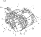
- FIG. 1 an electrified vehicle axle is shown, the drive unit 1 of which has an electric machine EM and a transmission.
- the electric machine EM is connected via a spur gear stage 2 and an axle differential 4 of the transmission to right and left flange shafts 5, 7, which lead to vehicle wheels 9 of the vehicle axle.
- a rotor shaft 11 of the electric machine EM is coaxially connected to a transmission input shaft 12 via an indicated torque coupling 6.
- a rotor 49 is seated on the rotor shaft 11 in a rotationally fixed manner and interacts with a stator 51 arranged in a rotationally fixed manner on the stator housing 23.
- a fixed gear 13 is located on the transmission input shaft 12 and is part of the spur gear stage 2.
- the fixed gear 13 of the transmission input shaft 12 meshes with a fixed gear 17 located on an intermediate shaft 15.
- a further fixed gear 19 is arranged on the intermediate shaft 15, which in turn meshes with an external gear 21 on the input side of the axle differential 4.
- the EM electric machine is installed transversely, i.e. aligned parallel to the axis of the two flange shafts 5, 7.
- the electric machine EM has a cylindrical stator housing 23 which is axially extended in the vehicle transverse direction y by a transmission housing 25. Both the spur gear stage 2 and the axle differential 4 are arranged in the transmission housing 25.
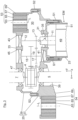
- the gear housing 25 is in the Fig. 2 and 3
- the housing is constructed in two parts, namely with an intermediate housing 27 and a housing cover 29.
- the intermediate housing 27 is designed according to the Fig. 3 at first screw points S1 on the front side of the stator housing 23.
- the housing cover 29 is flanged to the intermediate housing 27 via second screw points S2.
- the housing cover 29 closes the gear interior 30 ( Fig. 3 ).
- the transmission interior 30 is axially delimited in the vehicle transverse direction y by a bearing wall 31 of the intermediate housing 27 and by a bearing wall 33 of the housing cover 29.
- the bearing wall 31 of the intermediate housing 27 has a bearing opening 35 in which the rotor shaft 11 of the electric machine EM is rotatably mounted.
- the bearing wall 31 of the intermediate housing 27 has a shaft passage 39 in which the left flange shaft 5 is rotatably mounted. Furthermore, the bearing wall 31 of the intermediate housing 27 is designed with a rotary bearing point 41 for the intermediate shaft 15.
- the bearing wall 33 of the housing cover 29 has two bearing openings 43, 45 for the transmission input shaft 12 and for the intermediate shaft 15 as well as a shaft passage 47 in which the right flange shaft 7 is rotatably mounted.
- auxiliary frame 57 has in the Fig. 4 two lateral subframe longitudinal members 59, which are each connected to subframe cross members 61 at the front and rear of the vehicle.
- the core of the invention relates to the design of the three-point bearing.
- This has two gearbox-side assembly bearings 53, 54, via which the gearbox housing 25 is supported on the auxiliary frame 57.
- the two gearbox-side assembly bearings 53, 54 are arranged with respect to the flange shaft axis F ( Fig. 2 ) in the vehicle longitudinal direction x on opposite sides, i.e. at the front and rear of the vehicle.
- An example is shown in the Fig. 4 the first transmission-side assembly bearing 53 is connected to the rear subframe cross member 61, while the second transmission-side Aggregate bearing 54 is connected to the front subframe cross member 61.
- the third aggregate bearing 55 is arranged on the stator housing 23, which primarily supports the electric machine EM, in the area of which the center of gravity SP of the drive unit 1 is located.
- reaction forces F R are introduced from the vehicle wheels 9 into the axle differential 4 and from there into the rest of the drive unit 1 via the flange shafts 5, 7.
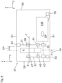
- the two transmission-side unit bearings 53, 54 are designed with an extremely small transverse offset ⁇ y 1 , ⁇ y 2 ( Fig. 4 ) to the axle differential 4.
- the unit bearings 53, 54, 55 are each designed as rubber-metal sleeve bearings, as used in the Fig. 3 are indicated. Accordingly, each of the shown assembly bearings 53, 54 has an inner, sleeve-shaped bearing core 63, which is connected to an outer sleeve 67 via an elastomer body 65. The radially inner bearing core 63 can be connected to bearing brackets of the auxiliary frame 57 via a bearing bolt (not shown).
- the bearing axes L of the two transmission-side assembly bearings 53, 54 and the stator housing-side assembly bearing 55 are in accordance with the Fig. 2 and 3 each aligned in the vehicle transverse direction y.
- the first transmission-side assembly bearing 53 is formed on the housing cover 29.
- the first transmission-side assembly bearing 53 lies together with the bearing wall 33 of the housing cover 29 in a common plane. In the case of load, the bearing wall 33 therefore acts as a component-rigid shear field.
- the second transmission-side assembly bearing 54 is formed on the intermediate housing 27.
- the second transmission-side assembly bearing 54 lies together with the bearing wall 33 of the intermediate housing 27 in a common plane, whereby the bearing wall 33 of the intermediate housing 27 also acts as a component-rigid shear field in the case of load.
Landscapes
- Engineering & Computer Science (AREA)
- General Engineering & Computer Science (AREA)
- Mechanical Engineering (AREA)
- Chemical & Material Sciences (AREA)
- Combustion & Propulsion (AREA)
- Transportation (AREA)
- Retarders (AREA)
- Motor Power Transmission Devices (AREA)
- General Details Of Gearings (AREA)
- Arrangement Or Mounting Of Propulsion Units For Vehicles (AREA)
Description
- Die Erfindung betrifft eine Antriebsvorrichtung für eine elektrifizierte Fahrzeugachse eines zweispurigen Fahrzeugs nach dem Oberbegriff des Anspruches 1.
- Eine elektrifizierte Fahrzeugachse für ein zweispuriges Kraftfahrzeug weist eine Elektromaschine auf, die über ein Getriebe auf Flanschwellen abtreibt, die jeweils zu einem Fahrzeugrad führen.
- Die Elektromaschine und das Getriebe sind Bestandteil eines Antriebsaggregats, das über eine Dreipunktlagerung oder eine Vierpunktlagerung zum Beispiel auf einem Hilfsrahmen der Fahrzeugkarosserie abgestützt ist. Das Getriebe weist eine Getriebestufe auf, über die die Elektromaschine mit einer Eingangsseite eines Achsdifferenzials trieblich verbunden ist. An deren Ausgangsseiten führen die Flanschwellen in Richtung des jeweiligen Fahrzeugrads.
- In einer gattungsgemäßen Antriebsvorrichtung ist die Elektromaschine achsparallel zu den Flanschwellen angeordnet. Ein Statorgehäuse der Elektromaschine ist in der Fahrzeugquerrichtung mit einem Getriebegehäuse axial verlängert, in dem die Getriebestufe sowie das Achsdifferenzial angeordnet sind. Das gattungsgemäße Antriebsaggregat ist in einer Dreipunktlagerung über drei Aggregatelager in der Fahrzeugkarosserie abgestützt. Während des Fahrbetriebs werden von den Fahrzeugrädern über die Flanschwellen Reaktionskräfte in das Achsdifferenzial und somit in das Antriebsaggregat eingeleitet. Für eine betriebssichere Momentenabstützung der Reaktionskräfte muss die Dreipunktlagerung entsprechend bauteilsteif, bauraumintensiv sowie materialaufwendig ausgelegt sein. Dadurch können sich aufgrund der hohen Packagedichte im Fahrwerk Bauraumprobleme ergeben.
- Aus der
DE 10 2012 012 327 A1 ist eine Anordnung einer Elektromotoreinheit im Motorraum eines Kraftfahrzeugs bekannt. Aus derDE 100 21 044 B4 ist ein Fahrzeug mit daran montiertem Brennstoffzellensystem bekannt. Aus derEP 1 674 316 B1 ist eine Befestigungskonstruktion für einen Antriebsmotor bekannt. Aus derDE 699 14 973 T2 ist eine Anordnung für ein elektrisches Antriebsaggregat bekannt. - Das Dokument
CN 109 435 659 A , das dem Gegenstand des Anspruchs 1 am nächsten kommt, zeigt eine Antriebsvorrichtung ähnlich wie die der vorliegenden Erfindung. - Die Aufgabe der Erfindung besteht darin, eine Antriebsvorrichtung für eine elektrifizierte Fahrzeugachse eines zweispurigen Fahrzeugs bereitzustellen, bei der die Dreipunktlagerung des Antriebsaggregats im Vergleich zum Stand der Technik mit reduziertem Bauteilaufwand, reduziertem Bauraumbedarf sowie reduziertem Materialaufwand realisierbar ist.
- Die Aufgabe ist durch die Merkmale des Anspruches 1 gelöst. Bevorzugte Weiterbildungen der Erfindung sind in den Unteransprüchen offenbart.
- Die Erfindung geht von einer Antriebsvorrichtung für eine elektrifizierte Fahrzeugachse eines zweispurigen Fahrzeugs aus. Diese weist ein Antriebsaggregat auf, in dem eine Elektromaschine über eine Getriebestufe mit einer Eingangsseite eines Achsdifferenzials trieblich verbunden ist. Das Achsdifferenzial treibt in der Fahrzeugquerrichtung beidseitig auf jeweils eine Flanschwelle ab, die zu einem Fahrzeugrad führt. Im Einbauzustand ist die Elektromaschine quer in der Fahrzeugachse eingebaut, das heißt achsparallel zu den Flanschwellen angeordnet. Ein Statorgehäuse der Elektromaschine ist in der Fahrzeugquerrichtung mit einem Getriebegehäuse axial verlängert, in dem die Getriebestufe und das Achsdifferenzial angeordnet sind. Das Antriebsaggregat ist in einer Dreipunktlagerung über genau drei Aggregatelager in der Fahrzeugkarosserie abgestützt. Im Fahrbetrieb werden von der Fahrbahn über die Flanschwellen Reaktionskräfte in das Achsdifferenzial und von dort weiter in das Antriebsaggregat geleitet. Ein Teil des Anspruches 1 betrifft eine Momentenabstützung dieser Reaktionskräfte, die im Vergleich zum Stand der Technik mit reduziertem Bauteilaufwand, reduziertem Bauraumbedarf sowie reduziertem Materialaufwand realisierbar ist. Hierzu weist die Dreipunktlagerung zwei getriebeseitige Aggregatelager auf, über die das Getriebegehäuse in der Fahrzeugkarosserie abgestützt ist. Die beiden getriebeseitigen Aggregatelager sind mit Bezug auf die Flanschwellen-Achse in der Fahrzeuglängsrichtung auf gegenüberliegenden Seiten angeordnet, wodurch in beiden Flanschwellen-Drehrichtungen eine Momentenabstützung bereitgestellt ist.
- Erfindungsgemäß wird das Getriebegehäuse aus insgesamt zwei Gehäuseteilen aufgebaut, die in der Fahrzeugquerrichtung axial hintereinander angeordnet sind. Die beiden Gehäuseteile sind ein am Statorgehäuse angeflanschtes Zwischengehäuse sowie ein Gehäusedeckel, der den Getriebegehäuse-Innenraum schließt. Der Gehäusedeckel und das Zwischengehäuse weisen jeweils eine Lagerwand auf. Die Lagerwände des Gehäusedeckels und des Zwischengehäuses liegen einander in der Fahrzeugquerrichtung axial gegenüber. Zudem weisen die Lagerwände jeweils Lagerstellen für die Getriebewellen sowie für die Flanschwellen auf. Für eine stabile Drehlagerung der Getriebewellen sowie der Flanschwellen sind der Gehäusedeckel sowie das Zwischengehäuse entsprechend bauteilsteif realisiert. Um eine betriebssichere Abstützung des Antriebsaggregats zu erzielen, ist es erfindungsgemäß, dass von den beiden getriebeseitigen Aggregatelagern ein erstes getriebeseitiges Aggregatelager am Gehäusedeckel ausgebildet ist, während das zweite getriebeseitige Aggregatelager am Zwischengehäuse ausgebildet ist. Sowohl der Gehäusedeckel als auch das Zwischengehäuse können als Metallgussteile bereitgestellt sein, an denen die getriebeseitigen Aggregatelager jeweils materialeinheitlich und einstückig abgeformt sind. Für eine einwandfreie Drehlagerung der Getriebewellen sowie der Flanschwellen sind die Lagerwände des Gehäusedeckels und des Zwischengehäuses mit entsprechendem Materialaufwand bauteilsteif ausgeführt. In einer bevorzugten Ausführungsform kann das erste getriebeseitige Aggregatelager in einer Lagerwand-Ebene des Gehäusedeckels liegen, während das zweite getriebeseitige Aggregatelager in einer Lagerwand-Ebene des Zwischengehäuses liegen kann. Auf diese Weise wirken die Lagerwände des Gehäusedeckels und des Zwischengehäuses in Doppelfunktion auch als Schubfelder, in denen während des Fahrbetriebs deformationsfrei Reaktionskräfte eingeleitet werden können, wodurch eine äußerst bauteilsteife Momentenabstützung erzielt werden kann.
- Infolge der Ausbildung der beiden Aggregatelager unmittelbar am Getriebegehäuse ergibt sich, in der Fahrzeugquerrichtung betrachtet, ein vergleichsweise geringer Querversatz (Hebelarmlänge) zum Achsdifferenzial, wodurch zum Beispiel Durchbiegungen oder Verwindungen des Antriebsaggregats aufgrund eingeleiteter Reaktionskräfte konstruktiv einfach unterbunden werden können.
- Wie oben erwähnt, sind die erfindungsgemäßen getriebeseitigen Aggregatelager Bestandteile einer Dreipunktlagerung. Im Gegensatz zu den beiden getriebeseitigen Aggregatelagern ist ein drittes Aggregatelager unmittelbar am Statorgehäuse ausgebildet, um dessen Bauteilgewicht betriebssicher abzustützen.
- Erfindungsgemäß wird jedes der Aggregatelager als ein Gummi-Metall-Hülsenlager ausgebildet, das in einem Befestigungsauge des Getriebegehäuses und/oder des Statorgehäuses eingepresst ist. Das Befestigungsauge kann jeweils materialeinheitlich und einstückig am Getriebegehäuse beziehungsweise am Statorgehäuse angeformt sein. Um eine besonders wirkungsvolle Momentenabstützung zu erzielen, ist es bevorzugt, wenn die Lagenachsen der beiden getriebeseitigen Aggregatelager sowie insbesondere zusätzlich des statorgehäuseseitigen Aggregatelagers achsparallel zur Flanschwelle-Achse ausgerichtet sind.
- Nachfolgend ist ein Ausführungsbeispiel der Erfindung anhand der beigefügten Figuren beschrieben.
- Es zeigen:
- Fig. 1
- in einer schematischen Darstellung eine elektrifizierte Fahrzeugachse;
- Fig. 2
- ein Antriebsaggregat in Alleinstellung;
- Fig. 3
- in einer Detailansicht ein Statorgehäuse, ein Zwischengehäuse sowie einen Gehäusedeckel des Antriebsaggregats; und
- Fig. 4
- ein schematisches Ersatzbild der Antriebsvorrichtung.
- In der
Fig. 1 ist eine elektrifizierte Fahrzeugachse gezeigt, deren Antriebsaggregat 1 eine Elektromaschine EM sowie ein Getriebe aufweist. Die Elektromaschine EM ist über eine Stirnradstufe 2 sowie über ein Achsdifferenzial 4 des Getriebes mit rechten und linken Flanschwellen 5, 7 verbunden, die zu Fahrzeugrädern 9 der Fahrzeugachse geführt sind. Eine Rotorwelle 11 der Elektromaschine EM ist über eine angedeutete Momentenkopplung 6 mit einer Getriebeeingangswelle 12 koaxial verbunden. Auf der Rotorwelle 11 sitzt drehfest ein Rotor 49, der mit einem drehfest am Statorgehäuse 23 angeordneten Stator 51 zusammenwirkt. - Auf der Getriebeeingangswelle 12 sitzt ein Festzahnrad 13, das Bestandteil der Stirnradstufe 2 ist. Das Festzahnrad 13 der Getriebeeingangswelle 12 kämmt mit einem auf einer Zwischenwelle 15 sitzenden Festzahnrad 17. Auf der Zwischenwelle 15 ist ein weiteres Festzahnrad 19 angeordnet, das wiederum mit einem eingangsseitigen Außenzahnrad 21 des Achsdifferenzials 4 in Zahneingriff ist. In der
Figur 1 ist die Elektromaschine EM im Quereinbau verbaut, das heißt achsparallel zu den beiden Flanschwellen 5, 7 ausgerichtet. - Wie aus den
Fig. 2 und3 weiter vorhergeht, weist die Elektromaschine EM ein zylindrisches Statorgehäuse 23 auf, das in der Fahrzeugquerrichtung y mit einem Getriebegehäuse 25 axial verlängert ist. Im Getriebegehäuse 25 sind sowohl die Stirnradstufe 2 als auch das Achsdifferenzial 4 angeordnet. - Das Getriebegehäuse 25 ist in den
Fig. 2 und3 zweiteilig aufgebaut, und zwar mit einem Zwischengehäuse 27 und einem Gehäusedeckel 29. Das Zwischengehäuse 27 ist gemäß derFig. 3 an ersten Schraubstellen S1 stirnseitig am Statorgehäuse 23 angeflanscht. Demgegenüber ist der Gehäusedeckel 29 über zweite Schraubstellen S2 am Zwischengehäuse 27 angeflanscht. Der Gehäusedeckel 29 schließt in Axialrichtung den Getriebe-Innenraum 30 (Fig. 3 ). In derFig.3 ist der Getriebe-Innenraum 30 in der Fahrzeugquerrichtung y durch eine Lagerwand 31 des Zwischengehäuses 27 und durch eine Lagerwand 33 des Gehäusedeckels 29 axial begrenzt. Die Lagerwand 31 des Zwischengehäuses 27 weist eine Lageröffnung 35 auf, in der die Rotorwelle 11 der Elektromaschine EM drehgelagert ist. Außerdem weist die Lagerwand 31 des Zwischengehäuses 27 einen Wellendurchtritt 39 auf, in der die linke Flanschwelle 5 drehgelagert ist. Ferner ist die Lagerwand 31 der Zwischengehäuses 27 mit einer Drehlagerstelle 41 für die Zwischenwelle 15 ausgebildet. Die Lagerwand 33 des Gehäusedeckels 29 weist zwei Lageröffnungen 43, 45 für die Getriebeeingangswelle 12 und für die Zwischenwelle 15 sowie einen Wellendurchtritt 47 auf, in der die rechte Flanschwelle 7 drehgelagert ist. - In der
Fig. 4 ist eine Einbaulage des Antriebsaggregats 1 angedeutet. Demzufolge ist das Antriebsaggregat 1 in einer Dreipunktlagerung mit insgesamt drei Aggregatelagern 53, 54, 55 auf einem grob schematisch angedeuteten Hilfsrahmen 57 abgestützt. Der Hilfsrahmen 57 weist in derFig. 4 zwei seitliche Hilfsrahmen-Längsträger 59 auf, die fahrzeugvorne und fahrzeughinten jeweils mit Hilfsrahmen-Querträgern 61 verbunden sind. - Der in Kern der Erfindung betrifft die Gestaltung der Dreipunktlagerung. Diese weist zwei getriebeseitige Aggregatelager 53, 54 auf, über die das Getriebegehäuse 25 auf dem Hilfsrahmen 57 abgestützt ist. Die beiden getriebeseitigen Aggregatelager 53, 54 sind mit Bezug auf die Flanschwellen-Achse F (
Fig. 2 ) in der Fahrzeuglängsrichtung x auf gegenüberliegenden Seiten, das heißt fahrzeugvorne und fahrzeughinten, angeordnet. Beispielhaft ist in derFig. 4 das erste getriebeseitige Aggregatelager 53 am hinteren Hilfsrahmen-Querträger 61 angebunden, während das zweite getriebeseitige Aggregatelager 54 am vorderen Hilfsrahmen-Querträger 61 angebunden ist. Das dritte Aggregatelager 55 ist dagegen am Statorgehäuse 23 angeordnet, wodurch in erster Linie die Elektromaschine EM abgestützt wird, in deren Bereich sich der Schwerpunkt SP des Antriebsaggregats 1 befindet. - Im Fahrzeugbetrieb werden über die Flanschwellen 5, 7 Reaktionskräfte FR von den Fahrzeugrädern 9 in das Achsdifferenzial 4 und von dort weiter in das restliche Antriebsaggregat 1 eingeleitet. Für eine stabile Momentenabstützung der Reaktionskräfte FR sind die beiden getriebeseitigen Aggregatelager 53, 54 in der Fahrzeugquerrichtung y betrachtet mit äußerst geringem Querversatz Δy1, Δy2 (
Fig. 4 ) zum Achsdifferenzial 4 positioniert. - Die Aggregatelager 53, 54, 55 sind jeweils als Gummi-Metall-Hülsenlager realisiert, wie sie in der
Fig. 3 angedeutet sind. Demzufolge weist jedes der gezeigten Aggregatelager 53, 54 einen inneren, hülsenförmigen Lagerkern 63 auf, der über einen Elastomerkörper 65 mit einer Außenhülse 67 verbunden ist. Der radial innere Lagerkern 63 ist über einen nicht gezeigten Lagerbolzen an Lagerkonsolen des Hilfsrahmens 57 anbindbar. Die Lagerachsen L der beiden getriebeseitigen Aggregatelager 53, 54 sowie des statorgehäuseseitigen Aggregatelagers 55 sind gemäß denFig. 2 und3 jeweils in Fahrzeugquerrichtung y ausgerichtet. - Wie aus der
Fig. 3 oder4 hervorgeht, ist das erste getriebeseitige Aggregatelager 53 am Gehäusedeckel 29 ausgebildet. Das erste getriebeseitige Aggregatelager 53 liegt zusammen mit der Lagerwand 33 des Gehäusedeckels 29 in einer gemeinsamen Ebene. Im Belastungsfall wirkt daher die Lagerwand 33 als ein bauteilsteifes Schubfeld. In gleicher Weise ist das zweite getriebeseitige Aggregatelager 54 am Zwischengehäuse 27 ausgebildet. Das zweite getriebeseitige Aggregatelager 54 liegt zusammen mit der Lagerwand 33 des Zwischengehäuses 27 in einer gemeinsamen Ebene, wodurch auch die Lagerwand 33 des Zwischengehäuses 27 im Belastungsfall als ein bauteilsteifes Schubfeld wirkt. -
- 1
- Antriebsaggregat
- 2
- Getriebe
- 3
- Stirnradstufe
- 4
- Achsdifferenzial
- 5, 7
- Flanschwellen
- 9
- Fahrzeugräder
- 11
- Rotorwelle
- 12
- Getriebeeingangswelle
- 13
- Festzahnrad
- 15
- Zwischenwelle
- 17
- Festzahnrad
- 23
- Statorgehäuse
- 25
- Getriebegehäuse
- 27
- Zwischengehäuse
- 29
- Gehäusedeckel
- 30
- Getriebe-Innenraum
- 31
- Lagerwand des Zwischengehäuses 27
- 33
- Lagerwand des Getriebedeckels 29
- 35
- Lageröffnung
- 39
- Wellendurchtritt
- 41
- Drehlagerstelle
- 43, 45
- Lageröffnungen
- 47
- Wellendurchtritt
- 49
- Rotorwelle
- 51
- Stator
- 53, 54, 55
- Aggregatelager
- 57
- Hilfsrahmen
- 59
- Hilfsrahmen-Längsträger
- 61
- Hilfsrahmen-Querträger
- 63
- Innerer Lagerkern
- 65
- Elastomerkörper
- 67
- Außenhülse
- S1, S2
- Schraubstellen
- L
- Lagerachsen
- F
- Flanschwellen-Achse
- Δy1, Δy2
- Querversatz
- FR
- Reaktionskräfte
Claims (5)
- Antriebsvorrichtung für eine elektrifizierte Fahrzeugachse eines zweispurigen Fahrzeugs, mit einem Antriebsaggregat (1), in dem eine Elektromaschine (EM) über ein Getriebe auf Fahrzeugräder (9) abtreibt, wobei die Elektromaschine (EM) im Quereinbau in der Fahrzeugachse angeordnet ist, wobei ein Statorgehäuse (23) der Elektromaschine (EM) in der Fahrzeugquerrichtung (y) mit einem Getriebegehäuse (25) axial verlängert ist, und wobei das Antriebsaggregat (1) in einer Dreipunktlagerung über drei Aggregatelager (53, 54, 55) in der Fahrzeugkarosserie abgestützt ist, wobei für eine Momentenabstützung von Reaktionskräften (FR) die Dreipunktlagerung zwei getriebeseitige Aggregatelager (53, 54) aufweist, über die das Getriebegehäuse (25) in der Fahrzeugkarosserie abgestützt ist, wobei das Getriebegehäuse (25) aus zwei Gehäuseteilen aufgebaut ist, die in der Fahrzeugquerrichtung (y) axial hintereinander angeordnet sind, und zwar aus einem am Statorgehäuse (23) angeflanschten Zwischengehäuse (27) und einem Gehäusedeckel (29), der den Getriebegehäuse-Innenraum (30) schließt, wobei der Gehäusedeckel (29) und das Zwischengehäuse (27) jeweils Lagerwände (31, 33) aufweisen, die einander axial gegenüber liegen, wobei in den Lagerwänden (31, 33) des Gehäusedeckels (29) und des Zwischengehäuses (27) Getriebewellen (11, 12, 15) sowie Flanschwellen (5, 7) drehgelagert sind, wobei das erste getriebeseitige Aggregatelager (53) am Gehäusedeckel (29) ausgebildet ist, und wobei das zweite getriebeseitige Aggregatelager (54) am Zwischengehäuse (27) ausgebildet ist,
dadurch gekennzeichnet, dass jedes der Aggregatelager (53, 54) als ein Gummi-Metall-Hülsenlager ausgebildet ist, das in einem Befestigungsauge (69) des Getriebegehäuses (25) eingepresst ist, dass das erste getriebeseitige Aggregatelager (53) in einer Lagerwand-Ebene des Gehäusedeckels (29) liegt, und/oder dass das zweite getriebeseitige Aggregatelager (54) in einer Lagerwand-Ebene des Zwischengehäuses (27) liegt. - Antriebsvorrichtung nach Anspruch 1, dadurch gekennzeichnet, dass die Elektromaschine (EM) über eine Getriebestufe (2) mit einer Eingangsseite eines Achsdifferenzials (4) trieblich verbunden ist, das beidseitig in einer Fahrzeugquerrichtung (y) auf Flanschwellen (5, 7) abtreibt, die jeweils zu einem Fahrzeugrad (9) führen, und/oder dass die Elektromaschine (EM) achsparallel zu den Flanschwellen (5, 7) angeordnet ist, und/oder dass in dem Getriebegehäuse (25) die Getriebestufe (2) und das Achsdifferenzial (4) angeordnet sind, und/oder dass insbesondere im Fahrbetrieb die Flanschwellen (5, 7) Reaktionskräfte (FR) über das Achsdifferenzial (4) in das Antriebsaggregat (1) einleiten.
- Antriebsvorrichtung nach Anspruch 1 oder 2, dadurch gekennzeichnet, dass infolge der Ausbildung am Getriebegehäuse (25) jedes der getriebeseitige Aggregatelager (53, 54), in der Fahrzeugquerrichtung (y) betrachtet, mit möglichst geringem Querversatz (Δy1, Δy2) zum Achsdifferenzial (4) positionierbar ist.
- Antriebsvorrichtung nach einem der vorhergehenden Ansprüche,
dadurch gekennzeichnet, dass das dritte Aggregatelager (55) am Statorgehäuse (23) ausgebildet ist. - Antriebsvorrichtung nach einem der vorhergehenden Ansprüche,
dadurch gekennzeichnet, dass die Lagerachsen (L) der beiden getriebeseitigen Aggregatelager (53, 54) sowie insbesondere zusätzlich des statorgehäuseseitigen Aggregatelagers (55) achsparallel zur Flanschwellen-Achse (F) ausgerichtet sind.
Applications Claiming Priority (2)
| Application Number | Priority Date | Filing Date | Title |
|---|---|---|---|
| DE102021132494.7A DE102021132494A1 (de) | 2021-12-09 | 2021-12-09 | Antriebsvorrichtung für eine Fahrzeugachse |
| PCT/EP2022/084494 WO2023104755A2 (de) | 2021-12-09 | 2022-12-06 | Antriebsvorrichtung für eine fahrzeugachse |
Publications (2)
| Publication Number | Publication Date |
|---|---|
| EP4408689A2 EP4408689A2 (de) | 2024-08-07 |
| EP4408689B1 true EP4408689B1 (de) | 2025-03-05 |
Family
ID=84688154
Family Applications (1)
| Application Number | Title | Priority Date | Filing Date |
|---|---|---|---|
| EP22830720.3A Active EP4408689B1 (de) | 2021-12-09 | 2022-12-06 | Antriebsvorrichtung für eine fahrzeugachse |
Country Status (5)
| Country | Link |
|---|---|
| US (1) | US12257894B2 (de) |
| EP (1) | EP4408689B1 (de) |
| CN (1) | CN118450996B (de) |
| DE (1) | DE102021132494A1 (de) |
| WO (1) | WO2023104755A2 (de) |
Citations (2)
| Publication number | Priority date | Publication date | Assignee | Title |
|---|---|---|---|---|
| US20200231050A1 (en) * | 2017-08-31 | 2020-07-23 | Honda Motor Co., Ltd. | Electric vehicle |
| US20200353982A1 (en) * | 2017-11-10 | 2020-11-12 | Volkswagen Aktiengesellschaft | Rear axle supporting frame comprising a moutning device for a drive unit |
Family Cites Families (13)
| Publication number | Priority date | Publication date | Assignee | Title |
|---|---|---|---|---|
| FR2780683B1 (fr) | 1998-07-03 | 2000-09-08 | Renault | Agencement pour un groupe motopropulseur electrique |
| JP4339953B2 (ja) | 1999-04-28 | 2009-10-07 | 本田技研工業株式会社 | 燃料電池システムを塔載する車両における機器の配置構造 |
| US7588117B2 (en) | 2003-09-29 | 2009-09-15 | Nissan Motor Co., Ltd. | Structure and method for mounting drive motor |
| JP2012206582A (ja) | 2011-03-29 | 2012-10-25 | Toyota Motor Corp | 電気自動車 |
| DE102012012327A1 (de) | 2012-06-20 | 2013-12-24 | Volkswagen Aktiengesellschaft | Anordnung einer Elektromotoreinheit im Motorraum eines Kraftfahrzeuges |
| DE102012212270B4 (de) * | 2012-07-13 | 2015-10-22 | Schaeffler Technologies AG & Co. KG | Achsantriebssystem für eine elektrische Achse |
| CN107531286B (zh) * | 2015-05-18 | 2019-07-12 | 宝马股份公司 | 具有车桥支架的机动车 |
| CN205768590U (zh) | 2016-05-24 | 2016-12-07 | 上汽通用五菱汽车股份有限公司 | 一种电动车动力总成悬置结构 |
| CN109435659B (zh) | 2018-11-20 | 2020-11-17 | 浙江吉利汽车研究院有限公司 | 电动汽车动力总成悬置系统及汽车 |
| JP6783884B2 (ja) * | 2019-02-20 | 2020-11-11 | 本田技研工業株式会社 | 車両駆動ユニット |
| CN111873774B (zh) | 2020-07-27 | 2021-10-22 | 东风汽车股份有限公司 | 一种电动汽车的后置后驱系统 |
| EP4095416B1 (de) * | 2021-05-27 | 2025-02-26 | Romax Technology Limited | Gekapselter getriebezug für eine maschine |
| US11692603B2 (en) * | 2021-07-26 | 2023-07-04 | GM Global Technology Operations LLC | Mount bushing with integrated isolated outer insert for enhanced high frequency isolation performance |
-
2021
- 2021-12-09 DE DE102021132494.7A patent/DE102021132494A1/de active Pending
-
2022
- 2022-12-06 CN CN202280081602.7A patent/CN118450996B/zh active Active
- 2022-12-06 US US18/709,315 patent/US12257894B2/en active Active
- 2022-12-06 EP EP22830720.3A patent/EP4408689B1/de active Active
- 2022-12-06 WO PCT/EP2022/084494 patent/WO2023104755A2/de not_active Ceased
Patent Citations (2)
| Publication number | Priority date | Publication date | Assignee | Title |
|---|---|---|---|---|
| US20200231050A1 (en) * | 2017-08-31 | 2020-07-23 | Honda Motor Co., Ltd. | Electric vehicle |
| US20200353982A1 (en) * | 2017-11-10 | 2020-11-12 | Volkswagen Aktiengesellschaft | Rear axle supporting frame comprising a moutning device for a drive unit |
Also Published As
| Publication number | Publication date |
|---|---|
| EP4408689A2 (de) | 2024-08-07 |
| US20250026196A1 (en) | 2025-01-23 |
| WO2023104755A2 (de) | 2023-06-15 |
| WO2023104755A3 (de) | 2023-08-03 |
| CN118450996B (zh) | 2025-03-21 |
| US12257894B2 (en) | 2025-03-25 |
| DE102021132494A1 (de) | 2023-06-15 |
| CN118450996A (zh) | 2024-08-06 |
Similar Documents
| Publication | Publication Date | Title |
|---|---|---|
| EP3263378B1 (de) | Batterie-elektrisch betriebenes nutzfahrzeug, insbesondere lastkraftwagen | |
| EP3372431B1 (de) | Antriebseinrichtung für ein kraftfahrzeug und kraftfahrzeug mit mindestens einer antriebseinrichtung | |
| WO2022156944A1 (de) | Antriebsstrang für ein kraftfahrzeug | |
| EP4493424B1 (de) | Antriebsvorrichtung für eine fahrzeugachse | |
| AT524089B1 (de) | Radantriebsmodul mit einem in dem Radantriebsmodul aufgenommenen Rad | |
| WO2009074389A2 (de) | Elektrischer antrieb | |
| DE202019103770U1 (de) | Doppelgetriebe mit vorteilhafter Auskragung | |
| EP3246188A1 (de) | Nutzfahrzeug mit einem parallel-hybrid-antriebsstrang | |
| DE19527951C2 (de) | Antriebseinheit zum Antrieb wenigstens eines Rades, insbesondere Radnabenantrieb | |
| DE102020117438A1 (de) | Antriebsmodul | |
| EP4408689B1 (de) | Antriebsvorrichtung für eine fahrzeugachse | |
| EP3594041A1 (de) | Achsen-generator-einheit mit vereinfachtem aufbau | |
| WO2002036991A1 (de) | Differential für den achsantrieb eines kraftfahrzeuges | |
| DE102004037266A1 (de) | Antriebsachse mit einem Elektromotor und integriertem Differentialgetriebe | |
| EP1502799B1 (de) | Radnabenantrieb | |
| DE102023200463A1 (de) | Antriebsstrang für eine Antriebsachse eines Fahrzeugs, Antriebsachse sowie Fahrzeug mit einer solchen Antriebsachse | |
| DE102009040817A1 (de) | Antriebseinheit für ein Kraftfahrzeug | |
| DE102018204909A1 (de) | Nebenabtriebsanordnung | |
| DE102022203955A1 (de) | Lenkbare Antriebseinheit für ein Flurförderzeug und Flurförderzeug | |
| DE102023203906A1 (de) | Antreibbare Starrachse, Baukastensystem und Arbeitsmaschine | |
| DE102007000962A1 (de) | Lenksystem, insbesondere für ein Kraftfahrzeug | |
| DE102018128833B4 (de) | Getriebevorrichtung für ein Kraftfahrzeug | |
| DE102024102821A1 (de) | Antriebseinheit, Antriebsachse und Kraftfahrzeug | |
| DE102024201036A1 (de) | Antriebsanordnung und ein Fahrzeug mit einer solchen Antriebsanordnung | |
| DE102024118752A1 (de) | Tragstruktur für ein Fahrzeug |
Legal Events
| Date | Code | Title | Description |
|---|---|---|---|
| STAA | Information on the status of an ep patent application or granted ep patent |
Free format text: STATUS: UNKNOWN |
|
| STAA | Information on the status of an ep patent application or granted ep patent |
Free format text: STATUS: THE INTERNATIONAL PUBLICATION HAS BEEN MADE |
|
| PUAI | Public reference made under article 153(3) epc to a published international application that has entered the european phase |
Free format text: ORIGINAL CODE: 0009012 |
|
| STAA | Information on the status of an ep patent application or granted ep patent |
Free format text: STATUS: REQUEST FOR EXAMINATION WAS MADE |
|
| 17P | Request for examination filed |
Effective date: 20240429 |
|
| AK | Designated contracting states |
Kind code of ref document: A2 Designated state(s): AL AT BE BG CH CY CZ DE DK EE ES FI FR GB GR HR HU IE IS IT LI LT LU LV MC ME MK MT NL NO PL PT RO RS SE SI SK SM TR |
|
| GRAP | Despatch of communication of intention to grant a patent |
Free format text: ORIGINAL CODE: EPIDOSNIGR1 |
|
| STAA | Information on the status of an ep patent application or granted ep patent |
Free format text: STATUS: GRANT OF PATENT IS INTENDED |
|
| DAV | Request for validation of the european patent (deleted) | ||
| DAX | Request for extension of the european patent (deleted) | ||
| INTG | Intention to grant announced |
Effective date: 20240924 |
|
| P01 | Opt-out of the competence of the unified patent court (upc) registered |
Free format text: CASE NUMBER: APP_59821/2024 Effective date: 20241105 |
|
| GRAS | Grant fee paid |
Free format text: ORIGINAL CODE: EPIDOSNIGR3 |
|
| GRAA | (expected) grant |
Free format text: ORIGINAL CODE: 0009210 |
|
| STAA | Information on the status of an ep patent application or granted ep patent |
Free format text: STATUS: THE PATENT HAS BEEN GRANTED |
|
| AK | Designated contracting states |
Kind code of ref document: B1 Designated state(s): AL AT BE BG CH CY CZ DE DK EE ES FI FR GB GR HR HU IE IS IT LI LT LU LV MC ME MK MT NL NO PL PT RO RS SE SI SK SM TR |
|
| REG | Reference to a national code |
Ref country code: GB Ref legal event code: FG4D Free format text: NOT ENGLISH |
|
| REG | Reference to a national code |
Ref country code: CH Ref legal event code: EP |
|
| REG | Reference to a national code |
Ref country code: IE Ref legal event code: FG4D Free format text: LANGUAGE OF EP DOCUMENT: GERMAN |
|
| REG | Reference to a national code |
Ref country code: DE Ref legal event code: R096 Ref document number: 502022003129 Country of ref document: DE |
|
| PG25 | Lapsed in a contracting state [announced via postgrant information from national office to epo] |
Ref country code: RS Free format text: LAPSE BECAUSE OF FAILURE TO SUBMIT A TRANSLATION OF THE DESCRIPTION OR TO PAY THE FEE WITHIN THE PRESCRIBED TIME-LIMIT Effective date: 20250605 |
|
| PG25 | Lapsed in a contracting state [announced via postgrant information from national office to epo] |
Ref country code: FI Free format text: LAPSE BECAUSE OF FAILURE TO SUBMIT A TRANSLATION OF THE DESCRIPTION OR TO PAY THE FEE WITHIN THE PRESCRIBED TIME-LIMIT Effective date: 20250305 |
|
| REG | Reference to a national code |
Ref country code: NL Ref legal event code: MP Effective date: 20250305 |
|
| PG25 | Lapsed in a contracting state [announced via postgrant information from national office to epo] |
Ref country code: ES Free format text: LAPSE BECAUSE OF FAILURE TO SUBMIT A TRANSLATION OF THE DESCRIPTION OR TO PAY THE FEE WITHIN THE PRESCRIBED TIME-LIMIT Effective date: 20250305 |
|
| REG | Reference to a national code |
Ref country code: LT Ref legal event code: MG9D |
|
| PG25 | Lapsed in a contracting state [announced via postgrant information from national office to epo] |
Ref country code: NO Free format text: LAPSE BECAUSE OF FAILURE TO SUBMIT A TRANSLATION OF THE DESCRIPTION OR TO PAY THE FEE WITHIN THE PRESCRIBED TIME-LIMIT Effective date: 20250605 |
|
| PG25 | Lapsed in a contracting state [announced via postgrant information from national office to epo] |
Ref country code: HR Free format text: LAPSE BECAUSE OF FAILURE TO SUBMIT A TRANSLATION OF THE DESCRIPTION OR TO PAY THE FEE WITHIN THE PRESCRIBED TIME-LIMIT Effective date: 20250305 |
|
| PG25 | Lapsed in a contracting state [announced via postgrant information from national office to epo] |
Ref country code: LV Free format text: LAPSE BECAUSE OF FAILURE TO SUBMIT A TRANSLATION OF THE DESCRIPTION OR TO PAY THE FEE WITHIN THE PRESCRIBED TIME-LIMIT Effective date: 20250305 |
|
| PG25 | Lapsed in a contracting state [announced via postgrant information from national office to epo] |
Ref country code: GR Free format text: LAPSE BECAUSE OF FAILURE TO SUBMIT A TRANSLATION OF THE DESCRIPTION OR TO PAY THE FEE WITHIN THE PRESCRIBED TIME-LIMIT Effective date: 20250606 Ref country code: BG Free format text: LAPSE BECAUSE OF FAILURE TO SUBMIT A TRANSLATION OF THE DESCRIPTION OR TO PAY THE FEE WITHIN THE PRESCRIBED TIME-LIMIT Effective date: 20250305 |
|
| PG25 | Lapsed in a contracting state [announced via postgrant information from national office to epo] |
Ref country code: NL Free format text: LAPSE BECAUSE OF FAILURE TO SUBMIT A TRANSLATION OF THE DESCRIPTION OR TO PAY THE FEE WITHIN THE PRESCRIBED TIME-LIMIT Effective date: 20250305 |
|
| PG25 | Lapsed in a contracting state [announced via postgrant information from national office to epo] |
Ref country code: SE Free format text: LAPSE BECAUSE OF FAILURE TO SUBMIT A TRANSLATION OF THE DESCRIPTION OR TO PAY THE FEE WITHIN THE PRESCRIBED TIME-LIMIT Effective date: 20250305 |
|
| PG25 | Lapsed in a contracting state [announced via postgrant information from national office to epo] |
Ref country code: SM Free format text: LAPSE BECAUSE OF FAILURE TO SUBMIT A TRANSLATION OF THE DESCRIPTION OR TO PAY THE FEE WITHIN THE PRESCRIBED TIME-LIMIT Effective date: 20250305 |
|
| PG25 | Lapsed in a contracting state [announced via postgrant information from national office to epo] |
Ref country code: PT Free format text: LAPSE BECAUSE OF FAILURE TO SUBMIT A TRANSLATION OF THE DESCRIPTION OR TO PAY THE FEE WITHIN THE PRESCRIBED TIME-LIMIT Effective date: 20250707 |
|
| PG25 | Lapsed in a contracting state [announced via postgrant information from national office to epo] |
Ref country code: PL Free format text: LAPSE BECAUSE OF FAILURE TO SUBMIT A TRANSLATION OF THE DESCRIPTION OR TO PAY THE FEE WITHIN THE PRESCRIBED TIME-LIMIT Effective date: 20250305 Ref country code: IT Free format text: LAPSE BECAUSE OF FAILURE TO SUBMIT A TRANSLATION OF THE DESCRIPTION OR TO PAY THE FEE WITHIN THE PRESCRIBED TIME-LIMIT Effective date: 20250305 |
|
| PG25 | Lapsed in a contracting state [announced via postgrant information from national office to epo] |
Ref country code: CZ Free format text: LAPSE BECAUSE OF FAILURE TO SUBMIT A TRANSLATION OF THE DESCRIPTION OR TO PAY THE FEE WITHIN THE PRESCRIBED TIME-LIMIT Effective date: 20250305 Ref country code: EE Free format text: LAPSE BECAUSE OF FAILURE TO SUBMIT A TRANSLATION OF THE DESCRIPTION OR TO PAY THE FEE WITHIN THE PRESCRIBED TIME-LIMIT Effective date: 20250305 |
|
| PG25 | Lapsed in a contracting state [announced via postgrant information from national office to epo] |
Ref country code: RO Free format text: LAPSE BECAUSE OF FAILURE TO SUBMIT A TRANSLATION OF THE DESCRIPTION OR TO PAY THE FEE WITHIN THE PRESCRIBED TIME-LIMIT Effective date: 20250305 |
|
| PG25 | Lapsed in a contracting state [announced via postgrant information from national office to epo] |
Ref country code: SK Free format text: LAPSE BECAUSE OF FAILURE TO SUBMIT A TRANSLATION OF THE DESCRIPTION OR TO PAY THE FEE WITHIN THE PRESCRIBED TIME-LIMIT Effective date: 20250305 |
|
| PG25 | Lapsed in a contracting state [announced via postgrant information from national office to epo] |
Ref country code: IS Free format text: LAPSE BECAUSE OF FAILURE TO SUBMIT A TRANSLATION OF THE DESCRIPTION OR TO PAY THE FEE WITHIN THE PRESCRIBED TIME-LIMIT Effective date: 20250705 |
|
| REG | Reference to a national code |
Ref country code: DE Ref legal event code: R097 Ref document number: 502022003129 Country of ref document: DE |
|
| PLBE | No opposition filed within time limit |
Free format text: ORIGINAL CODE: 0009261 |
|
| STAA | Information on the status of an ep patent application or granted ep patent |
Free format text: STATUS: NO OPPOSITION FILED WITHIN TIME LIMIT |
|
| PG25 | Lapsed in a contracting state [announced via postgrant information from national office to epo] |
Ref country code: DK Free format text: LAPSE BECAUSE OF FAILURE TO SUBMIT A TRANSLATION OF THE DESCRIPTION OR TO PAY THE FEE WITHIN THE PRESCRIBED TIME-LIMIT Effective date: 20250305 |
|
| PGFP | Annual fee paid to national office [announced via postgrant information from national office to epo] |
Ref country code: AT Payment date: 20260113 Year of fee payment: 4 |
|
| REG | Reference to a national code |
Ref country code: CH Ref legal event code: L10 Free format text: ST27 STATUS EVENT CODE: U-0-0-L10-L00 (AS PROVIDED BY THE NATIONAL OFFICE) Effective date: 20260114 |
|
| PGFP | Annual fee paid to national office [announced via postgrant information from national office to epo] |
Ref country code: FR Payment date: 20251218 Year of fee payment: 4 |