EP3965713B1 - Dispositif de réglage de la longueur d'un rail de mouvement de doigt, rail de mouvement de doigt réglable en longueur et appareil de thérapie comportant au moins un tel rail de mouvement de doigt réglable en longueur et procédé de réglage de la longueur - Google Patents
Dispositif de réglage de la longueur d'un rail de mouvement de doigt, rail de mouvement de doigt réglable en longueur et appareil de thérapie comportant au moins un tel rail de mouvement de doigt réglable en longueur et procédé de réglage de la longueur Download PDFInfo
- Publication number
- EP3965713B1 EP3965713B1 EP20727142.0A EP20727142A EP3965713B1 EP 3965713 B1 EP3965713 B1 EP 3965713B1 EP 20727142 A EP20727142 A EP 20727142A EP 3965713 B1 EP3965713 B1 EP 3965713B1
- Authority
- EP
- European Patent Office
- Prior art keywords
- rail
- adjustment
- blocking
- carriage
- movement
- Prior art date
- Legal status (The legal status is an assumption and is not a legal conclusion. Google has not performed a legal analysis and makes no representation as to the accuracy of the status listed.)
- Active
Links
Images

Classifications
-
- A—HUMAN NECESSITIES
- A61—MEDICAL OR VETERINARY SCIENCE; HYGIENE
- A61H—PHYSICAL THERAPY APPARATUS, e.g. DEVICES FOR LOCATING OR STIMULATING REFLEX POINTS IN THE BODY; ARTIFICIAL RESPIRATION; MASSAGE; BATHING DEVICES FOR SPECIAL THERAPEUTIC OR HYGIENIC PURPOSES OR SPECIFIC PARTS OF THE BODY
- A61H1/00—Apparatus for passive exercising; Vibrating apparatus; Chiropractic devices, e.g. body impacting devices, external devices for briefly extending or aligning unbroken bones
- A61H1/02—Stretching or bending or torsioning apparatus for exercising
- A61H1/0274—Stretching or bending or torsioning apparatus for exercising for the upper limbs
- A61H1/0285—Hand
- A61H1/0288—Fingers
-
- A—HUMAN NECESSITIES
- A61—MEDICAL OR VETERINARY SCIENCE; HYGIENE
- A61H—PHYSICAL THERAPY APPARATUS, e.g. DEVICES FOR LOCATING OR STIMULATING REFLEX POINTS IN THE BODY; ARTIFICIAL RESPIRATION; MASSAGE; BATHING DEVICES FOR SPECIAL THERAPEUTIC OR HYGIENIC PURPOSES OR SPECIFIC PARTS OF THE BODY
- A61H2201/00—Characteristics of apparatus not provided for in the preceding codes
- A61H2201/01—Constructive details
- A61H2201/0192—Specific means for adjusting dimensions
- A61H2201/0196—Specific means for adjusting dimensions automatically adjusted according to anthropometric data of the user
-
- A—HUMAN NECESSITIES
- A61—MEDICAL OR VETERINARY SCIENCE; HYGIENE
- A61H—PHYSICAL THERAPY APPARATUS, e.g. DEVICES FOR LOCATING OR STIMULATING REFLEX POINTS IN THE BODY; ARTIFICIAL RESPIRATION; MASSAGE; BATHING DEVICES FOR SPECIAL THERAPEUTIC OR HYGIENIC PURPOSES OR SPECIFIC PARTS OF THE BODY
- A61H2201/00—Characteristics of apparatus not provided for in the preceding codes
- A61H2201/12—Driving means
- A61H2201/1207—Driving means with electric or magnetic drive
- A61H2201/1215—Rotary drive
-
- A—HUMAN NECESSITIES
- A61—MEDICAL OR VETERINARY SCIENCE; HYGIENE
- A61H—PHYSICAL THERAPY APPARATUS, e.g. DEVICES FOR LOCATING OR STIMULATING REFLEX POINTS IN THE BODY; ARTIFICIAL RESPIRATION; MASSAGE; BATHING DEVICES FOR SPECIAL THERAPEUTIC OR HYGIENIC PURPOSES OR SPECIFIC PARTS OF THE BODY
- A61H2201/00—Characteristics of apparatus not provided for in the preceding codes
- A61H2201/12—Driving means
- A61H2201/1207—Driving means with electric or magnetic drive
- A61H2201/123—Linear drive
-
- A—HUMAN NECESSITIES
- A61—MEDICAL OR VETERINARY SCIENCE; HYGIENE
- A61H—PHYSICAL THERAPY APPARATUS, e.g. DEVICES FOR LOCATING OR STIMULATING REFLEX POINTS IN THE BODY; ARTIFICIAL RESPIRATION; MASSAGE; BATHING DEVICES FOR SPECIAL THERAPEUTIC OR HYGIENIC PURPOSES OR SPECIFIC PARTS OF THE BODY
- A61H2201/00—Characteristics of apparatus not provided for in the preceding codes
- A61H2201/14—Special force transmission means, i.e. between the driving means and the interface with the user
- A61H2201/1481—Special movement conversion means
- A61H2201/149—Special movement conversion means rotation-linear or vice versa
-
- A—HUMAN NECESSITIES
- A61—MEDICAL OR VETERINARY SCIENCE; HYGIENE
- A61H—PHYSICAL THERAPY APPARATUS, e.g. DEVICES FOR LOCATING OR STIMULATING REFLEX POINTS IN THE BODY; ARTIFICIAL RESPIRATION; MASSAGE; BATHING DEVICES FOR SPECIAL THERAPEUTIC OR HYGIENIC PURPOSES OR SPECIFIC PARTS OF THE BODY
- A61H2201/00—Characteristics of apparatus not provided for in the preceding codes
- A61H2201/16—Physical interface with patient
- A61H2201/1602—Physical interface with patient kind of interface, e.g. head rest, knee support or lumbar support
- A61H2201/1635—Hand or arm, e.g. handle
- A61H2201/1638—Holding means therefor
-
- A—HUMAN NECESSITIES
- A61—MEDICAL OR VETERINARY SCIENCE; HYGIENE
- A61H—PHYSICAL THERAPY APPARATUS, e.g. DEVICES FOR LOCATING OR STIMULATING REFLEX POINTS IN THE BODY; ARTIFICIAL RESPIRATION; MASSAGE; BATHING DEVICES FOR SPECIAL THERAPEUTIC OR HYGIENIC PURPOSES OR SPECIFIC PARTS OF THE BODY
- A61H2201/00—Characteristics of apparatus not provided for in the preceding codes
- A61H2201/16—Physical interface with patient
- A61H2201/1602—Physical interface with patient kind of interface, e.g. head rest, knee support or lumbar support
- A61H2201/165—Wearable interfaces
-
- A—HUMAN NECESSITIES
- A61—MEDICAL OR VETERINARY SCIENCE; HYGIENE
- A61H—PHYSICAL THERAPY APPARATUS, e.g. DEVICES FOR LOCATING OR STIMULATING REFLEX POINTS IN THE BODY; ARTIFICIAL RESPIRATION; MASSAGE; BATHING DEVICES FOR SPECIAL THERAPEUTIC OR HYGIENIC PURPOSES OR SPECIFIC PARTS OF THE BODY
- A61H2201/00—Characteristics of apparatus not provided for in the preceding codes
- A61H2201/16—Physical interface with patient
- A61H2201/1657—Movement of interface, i.e. force application means
- A61H2201/1664—Movement of interface, i.e. force application means linear
-
- A—HUMAN NECESSITIES
- A61—MEDICAL OR VETERINARY SCIENCE; HYGIENE
- A61H—PHYSICAL THERAPY APPARATUS, e.g. DEVICES FOR LOCATING OR STIMULATING REFLEX POINTS IN THE BODY; ARTIFICIAL RESPIRATION; MASSAGE; BATHING DEVICES FOR SPECIAL THERAPEUTIC OR HYGIENIC PURPOSES OR SPECIFIC PARTS OF THE BODY
- A61H2201/00—Characteristics of apparatus not provided for in the preceding codes
- A61H2201/16—Physical interface with patient
- A61H2201/1657—Movement of interface, i.e. force application means
- A61H2201/1676—Pivoting
-
- A—HUMAN NECESSITIES
- A61—MEDICAL OR VETERINARY SCIENCE; HYGIENE
- A61H—PHYSICAL THERAPY APPARATUS, e.g. DEVICES FOR LOCATING OR STIMULATING REFLEX POINTS IN THE BODY; ARTIFICIAL RESPIRATION; MASSAGE; BATHING DEVICES FOR SPECIAL THERAPEUTIC OR HYGIENIC PURPOSES OR SPECIFIC PARTS OF THE BODY
- A61H2205/00—Devices for specific parts of the body
- A61H2205/06—Arms
- A61H2205/065—Hands
- A61H2205/067—Fingers
Definitions
- the present invention relates to a length adjustment device for a finger movement splint of a therapy device for carrying out a continuous, passive and/or actively assisted movement of a finger and/or a thumb of a hand; a finger movement splint for carrying out such a movement with such a length adjustment device and a therapy device for carrying out a continuous, passive and/or actively assisted movement of at least one finger and/or a thumb of a hand, comprising at least one such finger movement splint.
- the present invention also relates to a method for adjusting the length of a finger movement splint on a therapy device for carrying out a continuous, passive and/or actively assisted movement of at least one finger and/or a thumb of a hand.
- Therapy devices with finger movement splints for the automated movement of individual and/or multiple fingers of a hand enable controlled joint mobilization regardless of the availability of physiotherapy staff. Through automated training that is independent of the time of day and individually tailored to the respective user, such devices improve the success of therapy in a cost-effective manner and shorten the user's recovery time.
- JP 2011 115 248 A and in the US 2014/028 86 64 A1 Devices for supporting finger movement are disclosed, the movement mechanism of which is arranged laterally next to the respective fingers, so that movement restriction by resting on the finger is avoided.
- the JP 2011 115 248 A discloses a device for supporting a movement, in particular a finger movement splint, which is said to be able to set a three-joint region to a natural bent position.
- a finger movement support device which uses sensor technology to determine the user's intention regarding a desired finger movement ("bending or stretching") and then supports this movement with the help of piezoelectric drives arranged on each finger joint.
- both devices can only be inadequately adapted to the differentiated anatomical shapes of the fingers or thumbs of different patients, which means that the automated movement of the fingers performed by them can deviate relatively significantly from a natural movement.
- a portable exoskeleton training robot for hand rehabilitation has become known.
- This training robot includes a fixation device for the hand, which can be attached to the back of the hand and the wrist, and rehabilitation devices for the fingers and thumb.
- the rehabilitation devices are each driven by linear motors.
- Threaded rods are available which allow at least manual length adjustment for each individual rehabilitation device.
- the EN 11 2017 000 012 B4 a therapy device for carrying out a continuous, passive and/or actively assisted movement of the fingers and thumb of a patient's hand, which allows each selected finger to be provided with its own finger movement splint with movement kinematics, which are arranged laterally to the finger to be treated and provide it with a allows for unrestricted bending and/or stretching movements.
- the well-known finger movement splint is based on a slide-rail movement kinematics, which enables an automated finger movement that is very close to an anatomically natural finger movement.
- a finger movement splint or a therapy device is described, the movement kinematics of which include a multi-joint hinge as a means of bending a metacarpophalangeal joint and is therefore particularly robust against the effects of axial forces and torsional forces on the finger movement splint.
- the movement principles of both of the aforementioned publications are hereby expressly referred to in full.
- the device in particular the individual finger movement splints, must be adjusted to the respective anatomy, i.e. to the hand size and/or the individual finger dimensions, before training begins.
- the individual finger movement splints are usually attached manually to the upper shell or holder of the respective therapy device in the optimal position for the respective user.
- the finger movement splints must then be manually removed after a training session and manually reattached in a different place for the next user. This procedure is time-consuming and, in everyday clinical practice, adversely reduces the training time available to the respective user with the therapy device.
- the object of the present invention is therefore to provide a device or a method which carries out the adaptation of a finger movement splint or a corresponding therapy device to the anatomy of the respective user quickly and cost-effectively in an automated manner.
- a length adjustment device for a finger movement splint of a therapy device for carrying out a continuous, passive and/or actively assisted movement of a finger and/or a thumb of a hand with the features of patent claim 1; by a finger movement splint for carrying out a continuous, passive and/or actively assisted movement of a finger and/or a thumb of a hand with the features of patent claim 11; by a therapy device for carrying out a continuous, passive and/or actively assisted movement of at least one finger and/or thumb of a hand with the features of patent claim 12; and by a method for adjusting the length of a finger movement rail on a therapy device for carrying out a continuous, passive and/or actively assisted movement of at least one finger and/or thumb of a hand with the features of patent claim 14.
- the carriage can preferably be operatively connected directly to the drive.
- the carriage can also be operatively connected indirectly to the drive via at least one connecting element.
- An embodiment in which the carriage can be operatively connected directly to the drive, in particular via a direct operative connection to a spindle of the drive, enables a comparatively simple construction of the length adjustment device, whereas an embodiment in which the carriage can be operatively connected indirectly to the drive via at least one connecting element promotes a comparatively compact, in particular flat construction of the length adjustment device.
- the adjustment rail is preferably a grid track with at least two grid elements.
- a grid track with at least two grid elements advantageously enables the holding means and thus also the finger movement rail to be locked onto the therapy device in a simple manner.
- the at least two grid elements protrude from the plane of the adjustment rail in a substantially wedge-shaped (triangular) and/or semicircular and/or in the form of a circular arc triangle (so-called "Reuleaux triangle”).
- Grid elements that protrude from the plane of the adjustment track in this way advantageously enable positive locking, whereby in the case of a wedge (triangular) shape and/or a semicircular shape and/or the shape of a circular arc triangle (so-called "Reuleaux triangle shape”) the effect of the blocking mechanism can be overcome more easily (with less effort) by exerting force using the slide than would be the case, for example, with grid elements that protrude from the plane in a cuboid shape.
- the at least two grid elements can also be designed as holes within the adjustment rail.
- An adjustment rail with holes as grid elements in the sense of a perforated plate advantageously enables a flatter construction of the adjustment rail.
- the holding means preferably has a first side wall for holding the blocking mechanisms and a second side wall for holding the finger movement rail, which are connected to one another at least via a base element, thereby forming a substantially U-shaped cross section through which the adjustment rail runs.
- a substantially U-shaped holding means advantageously enables simple and cost-effective production, depending on the material selected, for example by bending a metal sheet, by injection molding or 3D printing. In addition, such a holding means can easily be moved along the adjustment rail as a guide.
- the adjustment rail comprises a first side wall and a second side wall along its longitudinal axis, wherein the first side wall, the adjustment rail and the second side wall together form a substantially U-shaped cross section, and wherein the holding means is arranged to be movable within the substantially U-shaped cross section with respect to the adjustment rail.
- the blocking mechanisms each comprise at least one fixing means arranged on the holding means, preferably on the first side wall; a blocking lever pivoted on the holding means, preferably on the first side wall, via a rotation axis; and a means for springing the blocking lever relative to the fixing means, wherein the blocking lever is designed such that when the carriage comes into operative connection with the blocking lever, the blocking lever is rotated from a blocking position to an unblocking position and the holding means is thereby movable in at least one direction.
- a blocking mechanism advantageously enables a change in position of the holding means caused by the carriage and thus the drive of the finger movement rail and the the finger movement rail held by the holding device along the adjustment rail on the therapy device.
- the blocking mechanisms can also be designed as a single piece and made from a resilient material, in particular spring steel and/or hard rubber.
- the fixing means and the blocking levers can advantageously be made from a single piece of resilient material, with the blocking levers being arranged at an angle to the fixing means and the intersection points between the blocking levers and the fixing means corresponding to the axes of rotation.
- the means for suspension can be replaced by the spring properties of the resilient material, in particular the spring steel and/or the hard rubber, itself, which advantageously saves one component per blocking mechanism and reduces the size of the blocking mechanism.
- the blocking levers are operatively connected to the adjustment rail in their respective blocking position, in particular to the grid elements of an adjustment rail designed as a grid track, and in their respective unblocking position are not operatively connected to the adjustment rail, in particular to the grid elements of an adjustment rail designed as a grid track. If the blocking levers are operatively connected to the adjustment rail, in particular to the grid elements of an adjustment rail designed as a grid track, a movement of the holding means along the adjustment rail is advantageously prevented and the finger movement rail is held stable and securely in one position so that the therapy movement can be carried out safely.
- the holding means can advantageously be moved along the adjustment rail to any position or, in the case of an adjustment rail designed as a grid track, to a position depending on the grid elements or the holes.
- the present invention also relates to a finger movement splint for performing a continuous, passive and/or actively assisted movement of a finger and/or a thumb of a hand, comprising a length adjustment device according to one of claims 1 to 10.
- the present invention also relates to a therapy device for carrying out a continuous, passive and/or actively assisted movement of at least one finger and/or a thumb of a hand, comprising at least one drive for a finger movement rail and at least one finger movement rail according to claim 11.
- the drive is a linear drive, in particular a spindle motor, a pneumatic cylinder, a hydraulic cylinder and/or a cable pull.
- a linear drive advantageously enables a controlled movement of the carriage and thus both the finger movement rail during the execution of the therapy movement and the holding means together with the finger movement rail during length adjustment along the adjustment rail.
- the present invention relates to a method for adjusting the length of a finger movement rail on a therapy device for carrying out a continuous, passive and/or actively assisted movement of at least one finger and/or a thumb of a hand, which is characterized in that a connecting element of a finger movement rail arranged on a holding means is moved with the aid of a drive via a carriage along an adjustment rail from an amplitude for a therapy movement into a first or second adjustment range; wherein the carriage, when moved by means of the drive in a first direction along the adjustment rail into the first adjustment range, exerts a force on the first blocking mechanism upon contact with a first blocking mechanism, so that the first blocking mechanism is released and the holding means together with the finger movement rail is moved by movement of the carriage in the first direction, and wherein the carriage, when moved by means of the drive in a second direction along the adjustment rail into the second adjustment range, exerts a force on the second blocking mechanism upon contact with a second blocking mechanism, so that the second blocking mechanism is released and the holding means together with the finger
- a length adjustment device advantageously makes it possible to automatically move a finger movement rail along an adjustment rail using the drive already present for the finger movement rail on a therapy device and to fix it in a desired position - depending on the finger length or hand size/length of the user - on the adjustment rail and thus on the therapy device in order to then be able to carry out a continuous, passive and/or actively assisted movement of a finger and/or thumb of a hand in a stable position. Time-consuming manual adjustment is thus advantageously avoided.
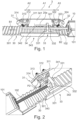
- Fig.1 shows an embodiment of a length adjustment device 3 according to the invention in a perspective view.
- the length adjustment device 3 for a finger movement rail 2 of a therapy device 1 for carrying out a continuous, passive and/or actively assisted movement of a finger and/or a thumb of a hand comprises at least one adjustment rail 30; at least one holding means 34 that can be moved with respect to the adjustment rail 30 for holding the finger movement rail 2; at least one first blocking mechanism 31 arranged on the holding means 34 for blocking the movement of the holding means 34 in a first direction B1 along the adjustment rail 30 and at least one second blocking mechanism 32 arranged on the holding means 34 for blocking the movement of the holding means 34 in a second direction B2 along the adjustment rail 30.
- Fig. 2 shows a part of a length adjustment device 3 according to Fig.1 with a blocking lever 312 in a release position P2.
- the holding means 34 may preferably have a first side wall 341 for holding the blocking mechanisms 31 and 32 and a second side wall 342 for holding the finger movement rail 2, which are connected to one another at least via a base element 343, thereby forming a substantially U-shaped cross section through which the adjustment rail 30 extends.
- the length adjustment device 3 comprises at least one carriage 33, wherein the carriage 33 is connected to the length adjustment device 3 via at least one connecting element 20a or 20b (cf. Fig.6 ) is operatively connected to the finger movement rail 2 and wherein the carriage 33 is arranged to be moved along the adjustment rail 30 by means of a drive 10 for moving the finger movement rail 2.
- the carriage 33 can be directly connected to the drive 10, in particular by a direct operative connection with a spindle 102 of the drive 10.
- the carriage 33 is designed according to the invention such that when it is moved by means of the drive 10 in the first direction B1 along the adjustment rail 30, upon contact with the first blocking mechanism 31, it exerts a force on the first blocking mechanism 31, so that the first blocking mechanism 31 is released and the holding means 34 together with the finger movement rail 2 can be moved by moving the carriage 30 in the first direction B1.
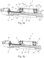
- Fig. 3a and 3b show such a movement of the holding means 34 along the adjustment rail 30 in the first direction B1.
- a connecting element 20a or 20b (cf. Fig.6 ) a finger movement rail 2 arranged on a holding means 34 is moved by means of a drive 10, in particular by means of the spindle 102 driven by the motor 101 of the drive 10, via a carriage 33 along an adjustment rail 30 from an amplitude A1 for a therapeutic movement into a first A2 or second A3 adjustment range.
- the blocking lever 312 is, as in Fig.
- the carriage 33 can comprise two sliding feet 331 and a cross element 332 connecting the sliding feet 331 to one another, so that the carriage 33 can have an H-shaped configuration in particular in plan view.
- the blocking lever 322 of the second blocking mechanism 32 does not block the movement of the holding means 34 in the first direction B1, but can simply be pulled along by the holding means 34 moved by the carriage 33.
- Fig. 3a shows the length adjustment device 3 from the Fig. 1 and 2 during the movement in direction B1, wherein a blocking lever 322 of the second blocking mechanism 32 is in a maximally deflected position above a grid element 301.
- Fig. 3b shows the same length adjustment device 3 in which the blocking lever 322 of the second blocking mechanism 32 is in a minimally deflected position.
- the carriage 30 of a length adjustment device 3 is designed such that when it is moved in the second direction B2 along the adjustment rail 30 by means of the drive 10, in particular by means of the spindle 102 driven by the motor 101 of the drive 10; upon contact with the second blocking mechanism 32, a force is exerted on the second blocking mechanism 32, so that the second blocking mechanism 32 is released and the holding means 34 together with the finger movement rail 2 can be moved in the second direction B2 by moving the carriage 30.
- the carriage 30 when the carriage 30 is moved by the drive 10 in a second direction B2 along the adjustment rail 30 into the second adjustment range A3, it exerts a force on the second blocking mechanism 32 upon contact with a second blocking mechanism 32, so that the second blocking mechanism 32 is released and the holding means 34 together with the finger movement rail 2 is moved in the second direction B2 by moving the carriage 33.
- the force can also be applied here via the sliding foot 331.
- the blocking lever 312 of the first blocking mechanism 31 blocks the movement of the holding means 34 in the second direction B2. but can simply be pulled along by the holding means 34 moved by the carriage 33.
- the adjustment rail 30 can in particular be a grid track with at least two grid elements 301.
- the at least two grid elements 301 can be designed as essentially wedge-shaped (triangular) - as in particular in the Fig. 1 to 3b shown - and/or semicircular and/or in the form of a circular arc triangle (so-called "Reuleaux triangle”) protrude from the plane of the adjustment rail 30.
- a circular arc triangle so-called "Reuleaux triangle
- the blocking levers 31 and 32 can interact with grid elements 301 protruding from the plane of the adjustment rail 30 in such a way that a blocking lever 31 or 32 blocks the movement of the holding means 34 in a direction of movement B1 or B2 and can be pulled over the grid elements 301 in the other direction of movement.
- the blocking mechanisms 31 and 32 preferably each comprise at least: a fixing means 314 or 324 arranged on the holding means 34, preferably on the first side wall 341; a blocking lever 312 or 322 pivoted on the holding means 34, preferably on the first side wall 341, via a rotation axis 311 or 321; and a means for springing 313 or 323 the blocking lever 312 or 322 relative to the fixing means 314 or 324; wherein the blocking lever 312 or 322 is designed such that when the carriage 33 comes into operative connection with the blocking lever 313 or 323, the blocking lever 312 or 323 is rotated from a blocking position P1 into a deblocking position P2 and the holding means 34 is thereby movable in at least one direction B1 or B2.
- the blocking levers 313 or 323 can preferably be in operative connection with the adjustment rail 30, in particular with the grid elements 301 of an adjustment rail 30 designed as a grid track, in their respective blocking position P1 and preferably not be in operative connection with the adjustment rail 30, in particular with the grid elements 301 of an adjustment rail 30 designed as a grid track, in their respective deblocking position P2.
- the blocking mechanisms 31 and 32 can also advantageously be designed in one piece. and be made of resilient material, in particular spring steel and/or hard rubber.
- Fig. 4a and Fig. 4b show a schematic comparison of a first, multi-part embodiment of a blocking mechanism 31 or 32 according to the invention ( Fig. 4a ) and a second embodiment of a blocking mechanism 31 or 32 according to the invention, formed in one piece from a resilient material ( Fig. 4b ).
- the fixing means 314 and 324 and the blocking levers 313 and 323 can advantageously be formed from a single piece of resilient material, for example from spring steel and/or hard rubber, wherein the blocking levers 313 and 323 are preferably arranged at an angle to the fixing means 314 and 324 and the intersection points between the blocking levers 313 and 323 and the fixing means 314 and 324 correspond to the axes of rotation 311 and 321.
- the at least two grid elements 301 of the adjustment rail 30 designed as a grid track can also be designed as holes within the adjustment rail 30 (not shown).
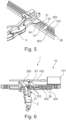
- Fig.5 shows a second embodiment of a length adjustment device 3 according to the invention with a finger movement rail 2, in which the adjustment rail 30 preferably comprises a first side wall 302 and a second side wall 303 along its longitudinal axis, wherein the first side wall 302, the adjustment rail 30 and the second side wall 303 together form a substantially U-shaped cross section, and wherein in particular the holding means 34 is arranged to be movable within the substantially U-shaped cross section with respect to the adjustment rail 30.
- the carriage 33 is preferably indirectly operatively connected to the drive 10 via at least one connecting element 103 (see also Fig.6 ).
- a side view of an embodiment of a finger movement rail 2 with length adjustment device 3 and drive 10 is shown.
- the drive 10 can preferably be a linear drive, in particular a spindle motor, a pneumatic cylinder, a hydraulic cylinder and/or a cable pull.
- Fig.6 shows exemplary a drive 10 designed as a spindle motor, the motor 101 of which drives a spindle 102, which in turn interacts with the carriage 33 via at least one connecting element 103.
- the connecting element 103 can preferably comprise at least one section that runs within the essentially U-shaped cross section formed by the adjustment rail 30, the first side wall 302 and the second side wall 303 (see also Fig.5 ).
- the length adjustment device 3 according to the invention or the method for length adjustment according to the invention advantageously makes it possible to automatically move a finger movement rail 2 along the adjustment rail 30 using the drive 10 already present for the finger movement rail 2 on a therapy device 1 and to fix it in a desired position - depending on the finger length or hand size/length of the user - on the adjustment rail 30 and thus on the therapy device 1 in order to then be able to carry out a continuous, passive and/or actively assisted movement of a finger and/or a thumb of a hand in a stable position. Time-consuming manual adjustment is thus advantageously avoided.
Landscapes
- Health & Medical Sciences (AREA)
- Animal Behavior & Ethology (AREA)
- Pain & Pain Management (AREA)
- Physical Education & Sports Medicine (AREA)
- Rehabilitation Therapy (AREA)
- Life Sciences & Earth Sciences (AREA)
- Epidemiology (AREA)
- General Health & Medical Sciences (AREA)
- Public Health (AREA)
- Veterinary Medicine (AREA)
- Rehabilitation Tools (AREA)
- Manipulator (AREA)
- Orthopedics, Nursing, And Contraception (AREA)
- Transmission Devices (AREA)
Claims (14)
- Dispositif de réglage de la longueur (3) pour un rail de déplacement de doigt (2) d'un appareil de thérapie (1) pour effectuer un déplacement continu, passif et/ou activement assisté d'un doigt et/ou d'un pouce d'une main, comprenant :- au moins un rail de réglage (30) ;- au moins un moyen de support (34) déplaçable par rapport au rail de réglage (30) pour supporter le rail de déplacement de doigt (2) ;- au moins un premier mécanisme de blocage (31) agencé sur le moyen de support (34) pour bloquer le déplacement du moyen de support (34) dans une première direction (B1) le long du rail de réglage (30) ;- au moins un deuxième mécanisme de blocage (32) agencé sur le moyen de support (34) pour bloquer le déplacement du moyen de support (34) dans une deuxième direction (B2) le long du rail de réglage (30) ;- au moins un chariot (33),- le chariot (33) pouvant être relié fonctionnellement par l'intermédiaire d'au moins un élément de liaison (20a ; 20b) avec le rail de déplacement de doigt (2) ;- le chariot (33) étant adapté pour être déplacé le long du rail de réglage (30) au moyen d'un entraînement (10) pour déplacer le rail de déplacement de doigt (2) ;- le chariot (33) étant conçu de telle sorte que, lorsqu'il est déplacé dans la première direction (B1) le long du rail de réglage (30) au moyen de l'entraînement (10), lors du contact avec le premier mécanisme de blocage (31), il exerce une force sur le premier mécanisme de blocage (31) de telle sorte que le premier mécanisme de blocage (31) est libéré et le moyen de support (34), avec le rail de déplacement de doigt (2), peut être déplacé par déplacement du chariot (33) dans la première direction (B1), et- le chariot (33) étant conçu de telle sorte que, lorsqu'il est déplacé dans la deuxième direction (B2) le long du rail de réglage (30) au moyen de l'entraînement (10), lors du contact avec le deuxième mécanisme de blocage (32), il exerce une force sur le deuxième mécanisme de blocage (32), de telle sorte que le deuxième mécanisme de blocage (32) est libéré et le moyen de support (34), avec le rail de déplacement de doigt (2), peut être déplacé par déplacement du chariot (33) dans la deuxième direction (B2).
- Dispositif de réglage de la longueur (3) selon la revendication 1, caractérisé en ce que le chariot (33) peut être relié fonctionnellement directement à l'entraînement (10) ; ou en ce que le chariot (33) peut être relié fonctionnellement indirectement à l'entraînement (10) par l'intermédiaire d'au moins un élément de liaison (103).
- Dispositif de réglage de la longueur (3) selon la revendication 1 ou 2, caractérisé en ce que le rail de réglage (30) est une piste à grille avec au moins deux éléments de grille (301).
- Dispositif de réglage de la longueur (3) selon la revendication 3, caractérisé en ce que les au moins deux éléments de grille (301) dépassent du plan du rail de réglage (30) essentiellement en forme de coin et/ou en forme de demi-cercle et/ou en forme d'arc de cercle triangulaire.
- Dispositif de réglage de la longueur (3) selon la revendication 3, caractérisé en ce que les au moins deux éléments de grille (301) sont conçus sous forme de trous à l'intérieur du rail de réglage (30).
- Dispositif de réglage de la longueur (3) selon l'une quelconque des revendications 1 à 5, caractérisé en ce que le moyen de support (34) présente une première paroi latérale (341) pour supporter les mécanismes de blocage (31 ; 32) et une deuxième paroi latérale (342) pour supporter le rail de déplacement de doigt (2), qui sont reliées entre elles au moins par l'intermédiaire d'un élément de fond (343), formant ainsi une section transversale essentiellement en forme de U à travers laquelle s'étend le rail de réglage (30).
- Dispositif de réglage de la longueur (3) selon l'une quelconque des revendications 1 à 5, caractérisé en ce que le rail de réglage (30) comprend une première paroi latérale (302) et une deuxième paroi latérale (303) le long de son axe longitudinal, la première paroi latérale (302), le rail de réglage (30) et la deuxième paroi latérale (303) formant ensemble une section transversale essentiellement en forme de U, et le moyen de support (34) étant agencé de manière déplaçable par rapport au rail de réglage (30) à l'intérieur de la section transversale essentiellement en forme de U.
- Dispositif de réglage de la longueur (3) selon l'une quelconque des revendications précédentes, caractérisé en ce que les mécanismes de blocage (31 ; 32) comprennent chacun au moins :- un moyen de fixation (314 ; 324) agencé sur le moyen de support (34), de préférence sur la première paroi latérale (341) ;- un levier de blocage (312 ; 322) articulé de manière rotative sur le moyen de support (34), de préférence sur la première paroi latérale (341), par l'intermédiaire d'un axe de rotation (311 ; 321) ;- et un moyen de suspension (313 ; 323) du levier de blocage (312 ; 322) par rapport au moyen de fixation (314 ; 324) ;- le levier de blocage (312 ; 323) étant conçu de telle sorte que, lorsque le chariot (33) entre en liaison fonctionnelle avec le levier de blocage (313 ; 323), le levier de blocage (312 ; 323) est tourné d'une position de blocage (P1) à une position de déblocage (P2) et le moyen de support (34) est ainsi déplaçable dans au moins une direction (B1 ; B2).
- Dispositif de réglage de la longueur (3) selon la revendication 8, caractérisé en ce que les mécanismes de blocage (31 ; 32) sont réalisés d'une seule pièce et sont formés d'un matériau élastique, notamment d'acier à ressort et/ou de caoutchouc dur.
- Dispositif de réglage de la longueur (3) selon la revendication 8 ou 9, caractérisé en ce que les leviers de blocage (313 ; 323)- sont, dans leur position de blocage respective (P1), en liaison fonctionnelle avec le rail de réglage (30), notamment avec les éléments de grille (301) d'un rail de réglage (30) réalisé sous forme de piste à grille, et- ne sont pas, dans leur position de déblocage respective (P2), en liaison fonctionnelle avec le rail de réglage (30), notamment avec les éléments de grille (301) d'un rail de réglage (30) réalisé sous forme de piste à grille.
- Rail de déplacement de doigt (2) pour effectuer un déplacement continu, passif et/ou activement assisté d'un doigt et/ou d'un pouce d'une main, comprenant un dispositif de réglage de la longueur (3) selon l'une quelconque des revendications 1 à 10.
- Appareil de thérapie (1) pour effectuer un déplacement continu, passif et/ou activement assisté d'au moins un doigt et/ou un pouce d'une main, comprenant au moins un entraînement (10) pour un rail de déplacement de doigt (2) et au moins un rail de déplacement de doigt (2) selon la revendication 11.
- Appareil de thérapie (1) selon la revendication 12, caractérisé en ce que l'entraînement (10) est un entraînement linéaire, notamment un moteur à broche, un vérin pneumatique, un vérin hydraulique et/ou un câble de traction.
- Procédé de réglage de la longueur d'un rail de déplacement de doigt (2) sur un appareil de thérapie (1) selon la revendication 12 ou 13 pour effectuer un déplacement continu, passif et/ou activement assisté d'au moins un doigt et/ou un pouce d'une main, dans lequel- un élément de liaison (20a ; 20b) d'un rail de déplacement de doigt (2) agencé sur un moyen de support (34) est déplacé à l'aide d'un entraînement (10) par l'intermédiaire d'un chariot (33) le long d'un rail de réglage (30) à partir d'une amplitude (A1) pour un déplacement thérapeutique dans une première (A2) ou une deuxième (A3) plage de réglage ;- le chariot (33), lorsqu'il est déplacé au moyen de l'entraînement (10) dans une première direction (B1) le long du rail de réglage (30) dans la première plage de réglage (A2), lors du contact avec un premier mécanisme de blocage (31), exerçant une force sur le premier mécanisme de blocage (31), de telle sorte que le premier mécanisme de blocage (31) est libéré et le moyen de support (34), avec le rail de déplacement de doigt (2), est déplacé dans la première direction (B1) par déplacement du chariot (30), et- le chariot (30), lorsqu'il est déplacé au moyen de l'entraînement (10) dans une deuxième direction (B2) le long du rail de réglage (30) dans la deuxième plage de réglage (A3), lors du contact avec un deuxième mécanisme de blocage (32), exerçant une force sur le deuxième mécanisme de blocage (10), de telle sorte que le deuxième mécanisme de blocage (32) est libéré et le moyen de support (34), avec le rail de déplacement de doigt (2), est déplacé dans la deuxième direction (B2) par déplacement du chariot (33).
Applications Claiming Priority (2)
| Application Number | Priority Date | Filing Date | Title |
|---|---|---|---|
| DE102019112051.9A DE102019112051B4 (de) | 2019-05-08 | 2019-05-08 | Längeneinstellvorrichtung für eine Finger-Bewegungsschiene, längeneinstellbare Finger-Bewegungsschiene und Therapiegerät mit wenigstens einer solchen längeneinstellbaren Finger-Bewegungsschiene sowie Verfahren zur Längeneinstellung |
| PCT/DE2020/100391 WO2020224728A1 (fr) | 2019-05-08 | 2020-05-08 | Dispositif de réglage de la longueur d'un rail de mouvement de doigt, rail de mouvement de doigt réglable en longueur et appareil de thérapie comportant au moins un tel rail de mouvement de doigt réglable en longueur et procédé de réglage de la longueur |
Publications (3)
| Publication Number | Publication Date |
|---|---|
| EP3965713A1 EP3965713A1 (fr) | 2022-03-16 |
| EP3965713B1 true EP3965713B1 (fr) | 2024-08-21 |
| EP3965713C0 EP3965713C0 (fr) | 2024-08-21 |
Family
ID=70779403
Family Applications (1)
| Application Number | Title | Priority Date | Filing Date |
|---|---|---|---|
| EP20727142.0A Active EP3965713B1 (fr) | 2019-05-08 | 2020-05-08 | Dispositif de réglage de la longueur d'un rail de mouvement de doigt, rail de mouvement de doigt réglable en longueur et appareil de thérapie comportant au moins un tel rail de mouvement de doigt réglable en longueur et procédé de réglage de la longueur |
Country Status (9)
| Country | Link |
|---|---|
| US (1) | US12220370B2 (fr) |
| EP (1) | EP3965713B1 (fr) |
| JP (1) | JP7518550B2 (fr) |
| KR (1) | KR20220006515A (fr) |
| CN (1) | CN113825480B (fr) |
| AU (1) | AU2020267624B2 (fr) |
| BR (1) | BR112021020161A2 (fr) |
| DE (2) | DE102019112051B4 (fr) |
| WO (1) | WO2020224728A1 (fr) |
Family Cites Families (17)
| Publication number | Priority date | Publication date | Assignee | Title |
|---|---|---|---|---|
| US5136911A (en) * | 1990-05-04 | 1992-08-11 | Wyss John R | Hand stretcher for musicians |
| US6565563B1 (en) * | 1996-09-23 | 2003-05-20 | John M. Agee | Method and apparatus for increasing the range of motion of one or more contracted joints through external forces independently transmitted to the skeleton |
| JP2011115248A (ja) | 2009-12-01 | 2011-06-16 | Oki Electric Industry Co Ltd | 装着型動作支援装置 |
| JP2014184027A (ja) | 2013-03-25 | 2014-10-02 | Seiko Epson Corp | 指アシスト装置 |
| KR101485414B1 (ko) * | 2013-05-03 | 2015-01-26 | 국립대학법인 울산과학기술대학교 산학협력단 | 가상 물체와의 상호작용을 위한 손 외골격 링크 구조체 |
| WO2016168054A1 (fr) * | 2015-04-14 | 2016-10-20 | Borgwarner Inc. | Système d'embrayage multimode à doubles leviers coudés |
| CN105457236B (zh) * | 2015-12-29 | 2017-12-01 | 中国科学院深圳先进技术研究院 | 康复训练手及康复训练方法 |
| CN108883023B (zh) * | 2016-02-15 | 2020-12-29 | 利姆医疗有限公司 | 用于执行患者的手的手指的辅助运动的治疗装置 |
| DE202016000943U1 (de) * | 2016-02-15 | 2016-05-09 | Pascal Lindemann | Halterung für Finger-Bewegungsschienen |
| CN105726263A (zh) * | 2016-04-19 | 2016-07-06 | 西安交通大学 | 一种穿戴式手部外骨骼康复训练机器人 |
| WO2018055812A1 (fr) | 2016-09-26 | 2018-03-29 | Cyberdyne株式会社 | Dispositif d'assistance au mouvement |
| CN107260490B (zh) * | 2017-07-12 | 2023-03-14 | 合肥工业大学 | 一种外骨骼式康复机械手 |
| KR102013344B1 (ko) * | 2017-07-26 | 2019-08-22 | 울산과학기술원 | 손 움직임 측정을 위한 착용형 메커니즘 |
| CN108272597B (zh) * | 2018-03-20 | 2024-03-01 | 上海念通智能科技有限公司 | 一种穿戴式手部康复训练与辅助运动设备 |
| CN108814898B (zh) | 2018-05-08 | 2023-10-31 | 合肥工业大学 | 一种手功能康复训练系统 |
| US11622587B2 (en) * | 2019-04-17 | 2023-04-11 | Harley Luplow | Self-tensioning and releasable gripping gloves |
| DE102019112049B4 (de) | 2019-05-08 | 2021-01-28 | Universitätsmedizin Der Johannes Gutenberg-Universität Mainz | Finger-Bewegungsschiene zur Durchführung einer kontinuierlichen, passiven und/oder aktiv-assistierten Bewegung eines Fingers und/oder eines Daumens eines Patienten, sowie Therapiegerät umfassend eine solche Finger-Bewegungsschiene |
-
2019
- 2019-05-08 DE DE102019112051.9A patent/DE102019112051B4/de active Active
-
2020
- 2020-05-08 KR KR1020217035628A patent/KR20220006515A/ko not_active Withdrawn
- 2020-05-08 CN CN202080034360.7A patent/CN113825480B/zh active Active
- 2020-05-08 WO PCT/DE2020/100391 patent/WO2020224728A1/fr not_active Ceased
- 2020-05-08 BR BR112021020161A patent/BR112021020161A2/pt not_active IP Right Cessation
- 2020-05-08 EP EP20727142.0A patent/EP3965713B1/fr active Active
- 2020-05-08 JP JP2021559710A patent/JP7518550B2/ja active Active
- 2020-05-08 AU AU2020267624A patent/AU2020267624B2/en not_active Expired - Fee Related
- 2020-05-08 DE DE112020002242.0T patent/DE112020002242A5/de not_active Withdrawn
- 2020-05-08 US US17/608,806 patent/US12220370B2/en active Active
Also Published As
| Publication number | Publication date |
|---|---|
| US12220370B2 (en) | 2025-02-11 |
| BR112021020161A2 (pt) | 2021-12-14 |
| WO2020224728A1 (fr) | 2020-11-12 |
| AU2020267624A1 (en) | 2021-10-28 |
| AU2020267624B2 (en) | 2025-02-06 |
| EP3965713C0 (fr) | 2024-08-21 |
| US20220296454A1 (en) | 2022-09-22 |
| CN113825480A (zh) | 2021-12-21 |
| CA3138890A1 (fr) | 2020-11-12 |
| DE112020002242A5 (de) | 2022-03-17 |
| DE102019112051A1 (de) | 2020-11-12 |
| CN113825480B (zh) | 2024-03-05 |
| DE102019112051B4 (de) | 2021-01-28 |
| JP2022531837A (ja) | 2022-07-12 |
| EP3965713A1 (fr) | 2022-03-16 |
| KR20220006515A (ko) | 2022-01-17 |
| JP7518550B2 (ja) | 2024-07-18 |
Similar Documents
| Publication | Publication Date | Title |
|---|---|---|
| EP3416605B1 (fr) | Appareil de thérapie | |
| DE2528583C3 (de) | Gerät zur chirurgischen Behandlung von Knochen und Gelenken | |
| DE60030256T2 (de) | Vorrichtung zur äusseren fixierung von knochen | |
| DE69011363T2 (de) | Vorrichtung zum externen Festlegen von Knochenfragmenten mit kontrollierbarer Dämpfung. | |
| DE1616142B1 (de) | Implantierbare Gelenkprothese | |
| EP3684299B1 (fr) | Élément modulaire destiné à l'utilisation dans une orthèse à main | |
| DE102016104879B4 (de) | Orthese | |
| DE102012003360A1 (de) | Fingerelement | |
| DE102004049447A1 (de) | Schiene zur passiven Mobilisierung des Knöchelgelenks | |
| EP3965712B1 (fr) | Rail de mouvement de doigt pour l'exécution d'un mouvement continu passif et/ou activement assisté d'un doigt et/ou d'un pouce d'un patient, ainsi qu'appareil de thérapie comprenant un tel rail de mouvement de doigt | |
| DE102014007743A1 (de) | Modulares Handelement | |
| EP4391978B1 (fr) | Articulation d'orthèse réglable pour la mise en mouvement et/ou l'immobilisation contrôlées d'une main et orthèse pourvue d'une telle articulation d'orthèse | |
| EP3965713B1 (fr) | Dispositif de réglage de la longueur d'un rail de mouvement de doigt, rail de mouvement de doigt réglable en longueur et appareil de thérapie comportant au moins un tel rail de mouvement de doigt réglable en longueur et procédé de réglage de la longueur | |
| DE102008029572B4 (de) | Trainings-Vorrichtung zum Aufbau der Muskulatur des Gehapparates | |
| AT509975B1 (de) | Mobile, tragbare handorthese | |
| DE102018009174A1 (de) | Handexoskelett | |
| DE10113797B4 (de) | Körperabstützvorrichtung für ein Bett | |
| CH680901A5 (fr) | ||
| DE102018103566A1 (de) | Fixateur externe | |
| DE2657143B2 (de) | Apparat zur chirurgischen Behandlung von Knochen und Körpergelenken | |
| EP1182977B1 (fr) | Dispositif de repositionnement de la colonne vertebrale | |
| EP1909713B1 (fr) | Orthèse pour une articulation | |
| DE202021105783U1 (de) | Orthese | |
| DE29711645U1 (de) | Trainingsgerät | |
| DE19960718A1 (de) | Kombimöbel Bücher-Sprossenwand |
Legal Events
| Date | Code | Title | Description |
|---|---|---|---|
| STAA | Information on the status of an ep patent application or granted ep patent |
Free format text: STATUS: UNKNOWN |
|
| STAA | Information on the status of an ep patent application or granted ep patent |
Free format text: STATUS: THE INTERNATIONAL PUBLICATION HAS BEEN MADE |
|
| PUAI | Public reference made under article 153(3) epc to a published international application that has entered the european phase |
Free format text: ORIGINAL CODE: 0009012 |
|
| STAA | Information on the status of an ep patent application or granted ep patent |
Free format text: STATUS: REQUEST FOR EXAMINATION WAS MADE |
|
| 17P | Request for examination filed |
Effective date: 20211202 |
|
| AK | Designated contracting states |
Kind code of ref document: A1 Designated state(s): AL AT BE BG CH CY CZ DE DK EE ES FI FR GB GR HR HU IE IS IT LI LT LU LV MC MK MT NL NO PL PT RO RS SE SI SK SM TR |
|
| DAV | Request for validation of the european patent (deleted) | ||
| DAX | Request for extension of the european patent (deleted) | ||
| GRAP | Despatch of communication of intention to grant a patent |
Free format text: ORIGINAL CODE: EPIDOSNIGR1 |
|
| STAA | Information on the status of an ep patent application or granted ep patent |
Free format text: STATUS: GRANT OF PATENT IS INTENDED |
|
| INTG | Intention to grant announced |
Effective date: 20240315 |
|
| GRAS | Grant fee paid |
Free format text: ORIGINAL CODE: EPIDOSNIGR3 |
|
| GRAA | (expected) grant |
Free format text: ORIGINAL CODE: 0009210 |
|
| STAA | Information on the status of an ep patent application or granted ep patent |
Free format text: STATUS: THE PATENT HAS BEEN GRANTED |
|
| AK | Designated contracting states |
Kind code of ref document: B1 Designated state(s): AL AT BE BG CH CY CZ DE DK EE ES FI FR GB GR HR HU IE IS IT LI LT LU LV MC MK MT NL NO PL PT RO RS SE SI SK SM TR |
|
| REG | Reference to a national code |
Ref country code: GB Ref legal event code: FG4D Free format text: NOT ENGLISH |
|
| REG | Reference to a national code |
Ref country code: CH Ref legal event code: EP |
|
| REG | Reference to a national code |
Ref country code: DE Ref legal event code: R096 Ref document number: 502020008952 Country of ref document: DE |
|
| REG | Reference to a national code |
Ref country code: IE Ref legal event code: FG4D Free format text: LANGUAGE OF EP DOCUMENT: GERMAN |
|
| U01 | Request for unitary effect filed |
Effective date: 20240821 |
|
| U07 | Unitary effect registered |
Designated state(s): AT BE BG DE DK EE FI FR IT LT LU LV MT NL PT RO SE SI Effective date: 20240902 |
|
| PG25 | Lapsed in a contracting state [announced via postgrant information from national office to epo] |
Ref country code: NO Free format text: LAPSE BECAUSE OF FAILURE TO SUBMIT A TRANSLATION OF THE DESCRIPTION OR TO PAY THE FEE WITHIN THE PRESCRIBED TIME-LIMIT Effective date: 20241121 |
|
| PG25 | Lapsed in a contracting state [announced via postgrant information from national office to epo] |
Ref country code: GR Free format text: LAPSE BECAUSE OF FAILURE TO SUBMIT A TRANSLATION OF THE DESCRIPTION OR TO PAY THE FEE WITHIN THE PRESCRIBED TIME-LIMIT Effective date: 20241122 |
|
| PG25 | Lapsed in a contracting state [announced via postgrant information from national office to epo] |
Ref country code: IS Free format text: LAPSE BECAUSE OF FAILURE TO SUBMIT A TRANSLATION OF THE DESCRIPTION OR TO PAY THE FEE WITHIN THE PRESCRIBED TIME-LIMIT Effective date: 20241221 |
|
| PG25 | Lapsed in a contracting state [announced via postgrant information from national office to epo] |
Ref country code: HR Free format text: LAPSE BECAUSE OF FAILURE TO SUBMIT A TRANSLATION OF THE DESCRIPTION OR TO PAY THE FEE WITHIN THE PRESCRIBED TIME-LIMIT Effective date: 20240821 |
|
| PG25 | Lapsed in a contracting state [announced via postgrant information from national office to epo] |
Ref country code: RS Free format text: LAPSE BECAUSE OF FAILURE TO SUBMIT A TRANSLATION OF THE DESCRIPTION OR TO PAY THE FEE WITHIN THE PRESCRIBED TIME-LIMIT Effective date: 20241121 Ref country code: ES Free format text: LAPSE BECAUSE OF FAILURE TO SUBMIT A TRANSLATION OF THE DESCRIPTION OR TO PAY THE FEE WITHIN THE PRESCRIBED TIME-LIMIT Effective date: 20240821 |
|
| PG25 | Lapsed in a contracting state [announced via postgrant information from national office to epo] |
Ref country code: RS Free format text: LAPSE BECAUSE OF FAILURE TO SUBMIT A TRANSLATION OF THE DESCRIPTION OR TO PAY THE FEE WITHIN THE PRESCRIBED TIME-LIMIT Effective date: 20241121 Ref country code: NO Free format text: LAPSE BECAUSE OF FAILURE TO SUBMIT A TRANSLATION OF THE DESCRIPTION OR TO PAY THE FEE WITHIN THE PRESCRIBED TIME-LIMIT Effective date: 20241121 Ref country code: IS Free format text: LAPSE BECAUSE OF FAILURE TO SUBMIT A TRANSLATION OF THE DESCRIPTION OR TO PAY THE FEE WITHIN THE PRESCRIBED TIME-LIMIT Effective date: 20241221 Ref country code: HR Free format text: LAPSE BECAUSE OF FAILURE TO SUBMIT A TRANSLATION OF THE DESCRIPTION OR TO PAY THE FEE WITHIN THE PRESCRIBED TIME-LIMIT Effective date: 20240821 Ref country code: GR Free format text: LAPSE BECAUSE OF FAILURE TO SUBMIT A TRANSLATION OF THE DESCRIPTION OR TO PAY THE FEE WITHIN THE PRESCRIBED TIME-LIMIT Effective date: 20241122 Ref country code: ES Free format text: LAPSE BECAUSE OF FAILURE TO SUBMIT A TRANSLATION OF THE DESCRIPTION OR TO PAY THE FEE WITHIN THE PRESCRIBED TIME-LIMIT Effective date: 20240821 |
|
| PG25 | Lapsed in a contracting state [announced via postgrant information from national office to epo] |
Ref country code: SM Free format text: LAPSE BECAUSE OF FAILURE TO SUBMIT A TRANSLATION OF THE DESCRIPTION OR TO PAY THE FEE WITHIN THE PRESCRIBED TIME-LIMIT Effective date: 20240821 |
|
| PG25 | Lapsed in a contracting state [announced via postgrant information from national office to epo] |
Ref country code: CZ Free format text: LAPSE BECAUSE OF FAILURE TO SUBMIT A TRANSLATION OF THE DESCRIPTION OR TO PAY THE FEE WITHIN THE PRESCRIBED TIME-LIMIT Effective date: 20240821 |
|
| PG25 | Lapsed in a contracting state [announced via postgrant information from national office to epo] |
Ref country code: SK Free format text: LAPSE BECAUSE OF FAILURE TO SUBMIT A TRANSLATION OF THE DESCRIPTION OR TO PAY THE FEE WITHIN THE PRESCRIBED TIME-LIMIT Effective date: 20240821 |
|
| PLBE | No opposition filed within time limit |
Free format text: ORIGINAL CODE: 0009261 |
|
| STAA | Information on the status of an ep patent application or granted ep patent |
Free format text: STATUS: NO OPPOSITION FILED WITHIN TIME LIMIT |
|
| U20 | Renewal fee for the european patent with unitary effect paid |
Year of fee payment: 6 Effective date: 20250527 |
|
| PGFP | Annual fee paid to national office [announced via postgrant information from national office to epo] |
Ref country code: PL Payment date: 20250425 Year of fee payment: 6 |
|
| PGFP | Annual fee paid to national office [announced via postgrant information from national office to epo] |
Ref country code: GB Payment date: 20250522 Year of fee payment: 6 |
|
| 26N | No opposition filed |
Effective date: 20250522 |