EP3965713B1 - Length-adjustment device for a finger motion rail, length-adjustable finger motion rail and therapeutic device comprising at least one length-adjustable finger motion rail of this type and method for length adjustment - Google Patents
Length-adjustment device for a finger motion rail, length-adjustable finger motion rail and therapeutic device comprising at least one length-adjustable finger motion rail of this type and method for length adjustment Download PDFInfo
- Publication number
- EP3965713B1 EP3965713B1 EP20727142.0A EP20727142A EP3965713B1 EP 3965713 B1 EP3965713 B1 EP 3965713B1 EP 20727142 A EP20727142 A EP 20727142A EP 3965713 B1 EP3965713 B1 EP 3965713B1
- Authority
- EP
- European Patent Office
- Prior art keywords
- rail
- adjustment
- blocking
- carriage
- movement
- Prior art date
- Legal status (The legal status is an assumption and is not a legal conclusion. Google has not performed a legal analysis and makes no representation as to the accuracy of the status listed.)
- Active
Links
Images

Classifications
-
- A—HUMAN NECESSITIES
- A61—MEDICAL OR VETERINARY SCIENCE; HYGIENE
- A61H—PHYSICAL THERAPY APPARATUS, e.g. DEVICES FOR LOCATING OR STIMULATING REFLEX POINTS IN THE BODY; ARTIFICIAL RESPIRATION; MASSAGE; BATHING DEVICES FOR SPECIAL THERAPEUTIC OR HYGIENIC PURPOSES OR SPECIFIC PARTS OF THE BODY
- A61H1/00—Apparatus for passive exercising; Vibrating apparatus; Chiropractic devices, e.g. body impacting devices, external devices for briefly extending or aligning unbroken bones
- A61H1/02—Stretching or bending or torsioning apparatus for exercising
- A61H1/0274—Stretching or bending or torsioning apparatus for exercising for the upper limbs
- A61H1/0285—Hand
- A61H1/0288—Fingers
-
- A—HUMAN NECESSITIES
- A61—MEDICAL OR VETERINARY SCIENCE; HYGIENE
- A61H—PHYSICAL THERAPY APPARATUS, e.g. DEVICES FOR LOCATING OR STIMULATING REFLEX POINTS IN THE BODY; ARTIFICIAL RESPIRATION; MASSAGE; BATHING DEVICES FOR SPECIAL THERAPEUTIC OR HYGIENIC PURPOSES OR SPECIFIC PARTS OF THE BODY
- A61H2201/00—Characteristics of apparatus not provided for in the preceding codes
- A61H2201/01—Constructive details
- A61H2201/0192—Specific means for adjusting dimensions
- A61H2201/0196—Specific means for adjusting dimensions automatically adjusted according to anthropometric data of the user
-
- A—HUMAN NECESSITIES
- A61—MEDICAL OR VETERINARY SCIENCE; HYGIENE
- A61H—PHYSICAL THERAPY APPARATUS, e.g. DEVICES FOR LOCATING OR STIMULATING REFLEX POINTS IN THE BODY; ARTIFICIAL RESPIRATION; MASSAGE; BATHING DEVICES FOR SPECIAL THERAPEUTIC OR HYGIENIC PURPOSES OR SPECIFIC PARTS OF THE BODY
- A61H2201/00—Characteristics of apparatus not provided for in the preceding codes
- A61H2201/12—Driving means
- A61H2201/1207—Driving means with electric or magnetic drive
- A61H2201/1215—Rotary drive
-
- A—HUMAN NECESSITIES
- A61—MEDICAL OR VETERINARY SCIENCE; HYGIENE
- A61H—PHYSICAL THERAPY APPARATUS, e.g. DEVICES FOR LOCATING OR STIMULATING REFLEX POINTS IN THE BODY; ARTIFICIAL RESPIRATION; MASSAGE; BATHING DEVICES FOR SPECIAL THERAPEUTIC OR HYGIENIC PURPOSES OR SPECIFIC PARTS OF THE BODY
- A61H2201/00—Characteristics of apparatus not provided for in the preceding codes
- A61H2201/12—Driving means
- A61H2201/1207—Driving means with electric or magnetic drive
- A61H2201/123—Linear drive
-
- A—HUMAN NECESSITIES
- A61—MEDICAL OR VETERINARY SCIENCE; HYGIENE
- A61H—PHYSICAL THERAPY APPARATUS, e.g. DEVICES FOR LOCATING OR STIMULATING REFLEX POINTS IN THE BODY; ARTIFICIAL RESPIRATION; MASSAGE; BATHING DEVICES FOR SPECIAL THERAPEUTIC OR HYGIENIC PURPOSES OR SPECIFIC PARTS OF THE BODY
- A61H2201/00—Characteristics of apparatus not provided for in the preceding codes
- A61H2201/14—Special force transmission means, i.e. between the driving means and the interface with the user
- A61H2201/1481—Special movement conversion means
- A61H2201/149—Special movement conversion means rotation-linear or vice versa
-
- A—HUMAN NECESSITIES
- A61—MEDICAL OR VETERINARY SCIENCE; HYGIENE
- A61H—PHYSICAL THERAPY APPARATUS, e.g. DEVICES FOR LOCATING OR STIMULATING REFLEX POINTS IN THE BODY; ARTIFICIAL RESPIRATION; MASSAGE; BATHING DEVICES FOR SPECIAL THERAPEUTIC OR HYGIENIC PURPOSES OR SPECIFIC PARTS OF THE BODY
- A61H2201/00—Characteristics of apparatus not provided for in the preceding codes
- A61H2201/16—Physical interface with patient
- A61H2201/1602—Physical interface with patient kind of interface, e.g. head rest, knee support or lumbar support
- A61H2201/1635—Hand or arm, e.g. handle
- A61H2201/1638—Holding means therefor
-
- A—HUMAN NECESSITIES
- A61—MEDICAL OR VETERINARY SCIENCE; HYGIENE
- A61H—PHYSICAL THERAPY APPARATUS, e.g. DEVICES FOR LOCATING OR STIMULATING REFLEX POINTS IN THE BODY; ARTIFICIAL RESPIRATION; MASSAGE; BATHING DEVICES FOR SPECIAL THERAPEUTIC OR HYGIENIC PURPOSES OR SPECIFIC PARTS OF THE BODY
- A61H2201/00—Characteristics of apparatus not provided for in the preceding codes
- A61H2201/16—Physical interface with patient
- A61H2201/1602—Physical interface with patient kind of interface, e.g. head rest, knee support or lumbar support
- A61H2201/165—Wearable interfaces
-
- A—HUMAN NECESSITIES
- A61—MEDICAL OR VETERINARY SCIENCE; HYGIENE
- A61H—PHYSICAL THERAPY APPARATUS, e.g. DEVICES FOR LOCATING OR STIMULATING REFLEX POINTS IN THE BODY; ARTIFICIAL RESPIRATION; MASSAGE; BATHING DEVICES FOR SPECIAL THERAPEUTIC OR HYGIENIC PURPOSES OR SPECIFIC PARTS OF THE BODY
- A61H2201/00—Characteristics of apparatus not provided for in the preceding codes
- A61H2201/16—Physical interface with patient
- A61H2201/1657—Movement of interface, i.e. force application means
- A61H2201/1664—Movement of interface, i.e. force application means linear
-
- A—HUMAN NECESSITIES
- A61—MEDICAL OR VETERINARY SCIENCE; HYGIENE
- A61H—PHYSICAL THERAPY APPARATUS, e.g. DEVICES FOR LOCATING OR STIMULATING REFLEX POINTS IN THE BODY; ARTIFICIAL RESPIRATION; MASSAGE; BATHING DEVICES FOR SPECIAL THERAPEUTIC OR HYGIENIC PURPOSES OR SPECIFIC PARTS OF THE BODY
- A61H2201/00—Characteristics of apparatus not provided for in the preceding codes
- A61H2201/16—Physical interface with patient
- A61H2201/1657—Movement of interface, i.e. force application means
- A61H2201/1676—Pivoting
-
- A—HUMAN NECESSITIES
- A61—MEDICAL OR VETERINARY SCIENCE; HYGIENE
- A61H—PHYSICAL THERAPY APPARATUS, e.g. DEVICES FOR LOCATING OR STIMULATING REFLEX POINTS IN THE BODY; ARTIFICIAL RESPIRATION; MASSAGE; BATHING DEVICES FOR SPECIAL THERAPEUTIC OR HYGIENIC PURPOSES OR SPECIFIC PARTS OF THE BODY
- A61H2205/00—Devices for specific parts of the body
- A61H2205/06—Arms
- A61H2205/065—Hands
- A61H2205/067—Fingers
Definitions
- the present invention relates to a length adjustment device for a finger movement splint of a therapy device for carrying out a continuous, passive and/or actively assisted movement of a finger and/or a thumb of a hand; a finger movement splint for carrying out such a movement with such a length adjustment device and a therapy device for carrying out a continuous, passive and/or actively assisted movement of at least one finger and/or a thumb of a hand, comprising at least one such finger movement splint.
- the present invention also relates to a method for adjusting the length of a finger movement splint on a therapy device for carrying out a continuous, passive and/or actively assisted movement of at least one finger and/or a thumb of a hand.
- Therapy devices with finger movement splints for the automated movement of individual and/or multiple fingers of a hand enable controlled joint mobilization regardless of the availability of physiotherapy staff. Through automated training that is independent of the time of day and individually tailored to the respective user, such devices improve the success of therapy in a cost-effective manner and shorten the user's recovery time.
- JP 2011 115 248 A and in the US 2014/028 86 64 A1 Devices for supporting finger movement are disclosed, the movement mechanism of which is arranged laterally next to the respective fingers, so that movement restriction by resting on the finger is avoided.
- the JP 2011 115 248 A discloses a device for supporting a movement, in particular a finger movement splint, which is said to be able to set a three-joint region to a natural bent position.
- a finger movement support device which uses sensor technology to determine the user's intention regarding a desired finger movement ("bending or stretching") and then supports this movement with the help of piezoelectric drives arranged on each finger joint.
- both devices can only be inadequately adapted to the differentiated anatomical shapes of the fingers or thumbs of different patients, which means that the automated movement of the fingers performed by them can deviate relatively significantly from a natural movement.
- a portable exoskeleton training robot for hand rehabilitation has become known.
- This training robot includes a fixation device for the hand, which can be attached to the back of the hand and the wrist, and rehabilitation devices for the fingers and thumb.
- the rehabilitation devices are each driven by linear motors.
- Threaded rods are available which allow at least manual length adjustment for each individual rehabilitation device.
- the EN 11 2017 000 012 B4 a therapy device for carrying out a continuous, passive and/or actively assisted movement of the fingers and thumb of a patient's hand, which allows each selected finger to be provided with its own finger movement splint with movement kinematics, which are arranged laterally to the finger to be treated and provide it with a allows for unrestricted bending and/or stretching movements.
- the well-known finger movement splint is based on a slide-rail movement kinematics, which enables an automated finger movement that is very close to an anatomically natural finger movement.
- a finger movement splint or a therapy device is described, the movement kinematics of which include a multi-joint hinge as a means of bending a metacarpophalangeal joint and is therefore particularly robust against the effects of axial forces and torsional forces on the finger movement splint.
- the movement principles of both of the aforementioned publications are hereby expressly referred to in full.
- the device in particular the individual finger movement splints, must be adjusted to the respective anatomy, i.e. to the hand size and/or the individual finger dimensions, before training begins.
- the individual finger movement splints are usually attached manually to the upper shell or holder of the respective therapy device in the optimal position for the respective user.
- the finger movement splints must then be manually removed after a training session and manually reattached in a different place for the next user. This procedure is time-consuming and, in everyday clinical practice, adversely reduces the training time available to the respective user with the therapy device.
- the object of the present invention is therefore to provide a device or a method which carries out the adaptation of a finger movement splint or a corresponding therapy device to the anatomy of the respective user quickly and cost-effectively in an automated manner.
- a length adjustment device for a finger movement splint of a therapy device for carrying out a continuous, passive and/or actively assisted movement of a finger and/or a thumb of a hand with the features of patent claim 1; by a finger movement splint for carrying out a continuous, passive and/or actively assisted movement of a finger and/or a thumb of a hand with the features of patent claim 11; by a therapy device for carrying out a continuous, passive and/or actively assisted movement of at least one finger and/or thumb of a hand with the features of patent claim 12; and by a method for adjusting the length of a finger movement rail on a therapy device for carrying out a continuous, passive and/or actively assisted movement of at least one finger and/or thumb of a hand with the features of patent claim 14.
- the carriage can preferably be operatively connected directly to the drive.
- the carriage can also be operatively connected indirectly to the drive via at least one connecting element.
- An embodiment in which the carriage can be operatively connected directly to the drive, in particular via a direct operative connection to a spindle of the drive, enables a comparatively simple construction of the length adjustment device, whereas an embodiment in which the carriage can be operatively connected indirectly to the drive via at least one connecting element promotes a comparatively compact, in particular flat construction of the length adjustment device.
- the adjustment rail is preferably a grid track with at least two grid elements.
- a grid track with at least two grid elements advantageously enables the holding means and thus also the finger movement rail to be locked onto the therapy device in a simple manner.
- the at least two grid elements protrude from the plane of the adjustment rail in a substantially wedge-shaped (triangular) and/or semicircular and/or in the form of a circular arc triangle (so-called "Reuleaux triangle”).
- Grid elements that protrude from the plane of the adjustment track in this way advantageously enable positive locking, whereby in the case of a wedge (triangular) shape and/or a semicircular shape and/or the shape of a circular arc triangle (so-called "Reuleaux triangle shape”) the effect of the blocking mechanism can be overcome more easily (with less effort) by exerting force using the slide than would be the case, for example, with grid elements that protrude from the plane in a cuboid shape.
- the at least two grid elements can also be designed as holes within the adjustment rail.
- An adjustment rail with holes as grid elements in the sense of a perforated plate advantageously enables a flatter construction of the adjustment rail.
- the holding means preferably has a first side wall for holding the blocking mechanisms and a second side wall for holding the finger movement rail, which are connected to one another at least via a base element, thereby forming a substantially U-shaped cross section through which the adjustment rail runs.
- a substantially U-shaped holding means advantageously enables simple and cost-effective production, depending on the material selected, for example by bending a metal sheet, by injection molding or 3D printing. In addition, such a holding means can easily be moved along the adjustment rail as a guide.
- the adjustment rail comprises a first side wall and a second side wall along its longitudinal axis, wherein the first side wall, the adjustment rail and the second side wall together form a substantially U-shaped cross section, and wherein the holding means is arranged to be movable within the substantially U-shaped cross section with respect to the adjustment rail.
- the blocking mechanisms each comprise at least one fixing means arranged on the holding means, preferably on the first side wall; a blocking lever pivoted on the holding means, preferably on the first side wall, via a rotation axis; and a means for springing the blocking lever relative to the fixing means, wherein the blocking lever is designed such that when the carriage comes into operative connection with the blocking lever, the blocking lever is rotated from a blocking position to an unblocking position and the holding means is thereby movable in at least one direction.
- a blocking mechanism advantageously enables a change in position of the holding means caused by the carriage and thus the drive of the finger movement rail and the the finger movement rail held by the holding device along the adjustment rail on the therapy device.
- the blocking mechanisms can also be designed as a single piece and made from a resilient material, in particular spring steel and/or hard rubber.
- the fixing means and the blocking levers can advantageously be made from a single piece of resilient material, with the blocking levers being arranged at an angle to the fixing means and the intersection points between the blocking levers and the fixing means corresponding to the axes of rotation.
- the means for suspension can be replaced by the spring properties of the resilient material, in particular the spring steel and/or the hard rubber, itself, which advantageously saves one component per blocking mechanism and reduces the size of the blocking mechanism.
- the blocking levers are operatively connected to the adjustment rail in their respective blocking position, in particular to the grid elements of an adjustment rail designed as a grid track, and in their respective unblocking position are not operatively connected to the adjustment rail, in particular to the grid elements of an adjustment rail designed as a grid track. If the blocking levers are operatively connected to the adjustment rail, in particular to the grid elements of an adjustment rail designed as a grid track, a movement of the holding means along the adjustment rail is advantageously prevented and the finger movement rail is held stable and securely in one position so that the therapy movement can be carried out safely.
- the holding means can advantageously be moved along the adjustment rail to any position or, in the case of an adjustment rail designed as a grid track, to a position depending on the grid elements or the holes.
- the present invention also relates to a finger movement splint for performing a continuous, passive and/or actively assisted movement of a finger and/or a thumb of a hand, comprising a length adjustment device according to one of claims 1 to 10.
- the present invention also relates to a therapy device for carrying out a continuous, passive and/or actively assisted movement of at least one finger and/or a thumb of a hand, comprising at least one drive for a finger movement rail and at least one finger movement rail according to claim 11.
- the drive is a linear drive, in particular a spindle motor, a pneumatic cylinder, a hydraulic cylinder and/or a cable pull.
- a linear drive advantageously enables a controlled movement of the carriage and thus both the finger movement rail during the execution of the therapy movement and the holding means together with the finger movement rail during length adjustment along the adjustment rail.
- the present invention relates to a method for adjusting the length of a finger movement rail on a therapy device for carrying out a continuous, passive and/or actively assisted movement of at least one finger and/or a thumb of a hand, which is characterized in that a connecting element of a finger movement rail arranged on a holding means is moved with the aid of a drive via a carriage along an adjustment rail from an amplitude for a therapy movement into a first or second adjustment range; wherein the carriage, when moved by means of the drive in a first direction along the adjustment rail into the first adjustment range, exerts a force on the first blocking mechanism upon contact with a first blocking mechanism, so that the first blocking mechanism is released and the holding means together with the finger movement rail is moved by movement of the carriage in the first direction, and wherein the carriage, when moved by means of the drive in a second direction along the adjustment rail into the second adjustment range, exerts a force on the second blocking mechanism upon contact with a second blocking mechanism, so that the second blocking mechanism is released and the holding means together with the finger
- a length adjustment device advantageously makes it possible to automatically move a finger movement rail along an adjustment rail using the drive already present for the finger movement rail on a therapy device and to fix it in a desired position - depending on the finger length or hand size/length of the user - on the adjustment rail and thus on the therapy device in order to then be able to carry out a continuous, passive and/or actively assisted movement of a finger and/or thumb of a hand in a stable position. Time-consuming manual adjustment is thus advantageously avoided.
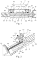
- Fig.1 shows an embodiment of a length adjustment device 3 according to the invention in a perspective view.
- the length adjustment device 3 for a finger movement rail 2 of a therapy device 1 for carrying out a continuous, passive and/or actively assisted movement of a finger and/or a thumb of a hand comprises at least one adjustment rail 30; at least one holding means 34 that can be moved with respect to the adjustment rail 30 for holding the finger movement rail 2; at least one first blocking mechanism 31 arranged on the holding means 34 for blocking the movement of the holding means 34 in a first direction B1 along the adjustment rail 30 and at least one second blocking mechanism 32 arranged on the holding means 34 for blocking the movement of the holding means 34 in a second direction B2 along the adjustment rail 30.
- Fig. 2 shows a part of a length adjustment device 3 according to Fig.1 with a blocking lever 312 in a release position P2.
- the holding means 34 may preferably have a first side wall 341 for holding the blocking mechanisms 31 and 32 and a second side wall 342 for holding the finger movement rail 2, which are connected to one another at least via a base element 343, thereby forming a substantially U-shaped cross section through which the adjustment rail 30 extends.
- the length adjustment device 3 comprises at least one carriage 33, wherein the carriage 33 is connected to the length adjustment device 3 via at least one connecting element 20a or 20b (cf. Fig.6 ) is operatively connected to the finger movement rail 2 and wherein the carriage 33 is arranged to be moved along the adjustment rail 30 by means of a drive 10 for moving the finger movement rail 2.
- the carriage 33 can be directly connected to the drive 10, in particular by a direct operative connection with a spindle 102 of the drive 10.
- the carriage 33 is designed according to the invention such that when it is moved by means of the drive 10 in the first direction B1 along the adjustment rail 30, upon contact with the first blocking mechanism 31, it exerts a force on the first blocking mechanism 31, so that the first blocking mechanism 31 is released and the holding means 34 together with the finger movement rail 2 can be moved by moving the carriage 30 in the first direction B1.
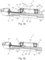
- Fig. 3a and 3b show such a movement of the holding means 34 along the adjustment rail 30 in the first direction B1.
- a connecting element 20a or 20b (cf. Fig.6 ) a finger movement rail 2 arranged on a holding means 34 is moved by means of a drive 10, in particular by means of the spindle 102 driven by the motor 101 of the drive 10, via a carriage 33 along an adjustment rail 30 from an amplitude A1 for a therapeutic movement into a first A2 or second A3 adjustment range.
- the blocking lever 312 is, as in Fig.
- the carriage 33 can comprise two sliding feet 331 and a cross element 332 connecting the sliding feet 331 to one another, so that the carriage 33 can have an H-shaped configuration in particular in plan view.
- the blocking lever 322 of the second blocking mechanism 32 does not block the movement of the holding means 34 in the first direction B1, but can simply be pulled along by the holding means 34 moved by the carriage 33.
- Fig. 3a shows the length adjustment device 3 from the Fig. 1 and 2 during the movement in direction B1, wherein a blocking lever 322 of the second blocking mechanism 32 is in a maximally deflected position above a grid element 301.
- Fig. 3b shows the same length adjustment device 3 in which the blocking lever 322 of the second blocking mechanism 32 is in a minimally deflected position.
- the carriage 30 of a length adjustment device 3 is designed such that when it is moved in the second direction B2 along the adjustment rail 30 by means of the drive 10, in particular by means of the spindle 102 driven by the motor 101 of the drive 10; upon contact with the second blocking mechanism 32, a force is exerted on the second blocking mechanism 32, so that the second blocking mechanism 32 is released and the holding means 34 together with the finger movement rail 2 can be moved in the second direction B2 by moving the carriage 30.
- the carriage 30 when the carriage 30 is moved by the drive 10 in a second direction B2 along the adjustment rail 30 into the second adjustment range A3, it exerts a force on the second blocking mechanism 32 upon contact with a second blocking mechanism 32, so that the second blocking mechanism 32 is released and the holding means 34 together with the finger movement rail 2 is moved in the second direction B2 by moving the carriage 33.
- the force can also be applied here via the sliding foot 331.
- the blocking lever 312 of the first blocking mechanism 31 blocks the movement of the holding means 34 in the second direction B2. but can simply be pulled along by the holding means 34 moved by the carriage 33.
- the adjustment rail 30 can in particular be a grid track with at least two grid elements 301.
- the at least two grid elements 301 can be designed as essentially wedge-shaped (triangular) - as in particular in the Fig. 1 to 3b shown - and/or semicircular and/or in the form of a circular arc triangle (so-called "Reuleaux triangle”) protrude from the plane of the adjustment rail 30.
- a circular arc triangle so-called "Reuleaux triangle
- the blocking levers 31 and 32 can interact with grid elements 301 protruding from the plane of the adjustment rail 30 in such a way that a blocking lever 31 or 32 blocks the movement of the holding means 34 in a direction of movement B1 or B2 and can be pulled over the grid elements 301 in the other direction of movement.
- the blocking mechanisms 31 and 32 preferably each comprise at least: a fixing means 314 or 324 arranged on the holding means 34, preferably on the first side wall 341; a blocking lever 312 or 322 pivoted on the holding means 34, preferably on the first side wall 341, via a rotation axis 311 or 321; and a means for springing 313 or 323 the blocking lever 312 or 322 relative to the fixing means 314 or 324; wherein the blocking lever 312 or 322 is designed such that when the carriage 33 comes into operative connection with the blocking lever 313 or 323, the blocking lever 312 or 323 is rotated from a blocking position P1 into a deblocking position P2 and the holding means 34 is thereby movable in at least one direction B1 or B2.
- the blocking levers 313 or 323 can preferably be in operative connection with the adjustment rail 30, in particular with the grid elements 301 of an adjustment rail 30 designed as a grid track, in their respective blocking position P1 and preferably not be in operative connection with the adjustment rail 30, in particular with the grid elements 301 of an adjustment rail 30 designed as a grid track, in their respective deblocking position P2.
- the blocking mechanisms 31 and 32 can also advantageously be designed in one piece. and be made of resilient material, in particular spring steel and/or hard rubber.
- Fig. 4a and Fig. 4b show a schematic comparison of a first, multi-part embodiment of a blocking mechanism 31 or 32 according to the invention ( Fig. 4a ) and a second embodiment of a blocking mechanism 31 or 32 according to the invention, formed in one piece from a resilient material ( Fig. 4b ).
- the fixing means 314 and 324 and the blocking levers 313 and 323 can advantageously be formed from a single piece of resilient material, for example from spring steel and/or hard rubber, wherein the blocking levers 313 and 323 are preferably arranged at an angle to the fixing means 314 and 324 and the intersection points between the blocking levers 313 and 323 and the fixing means 314 and 324 correspond to the axes of rotation 311 and 321.
- the at least two grid elements 301 of the adjustment rail 30 designed as a grid track can also be designed as holes within the adjustment rail 30 (not shown).
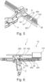
- Fig.5 shows a second embodiment of a length adjustment device 3 according to the invention with a finger movement rail 2, in which the adjustment rail 30 preferably comprises a first side wall 302 and a second side wall 303 along its longitudinal axis, wherein the first side wall 302, the adjustment rail 30 and the second side wall 303 together form a substantially U-shaped cross section, and wherein in particular the holding means 34 is arranged to be movable within the substantially U-shaped cross section with respect to the adjustment rail 30.
- the carriage 33 is preferably indirectly operatively connected to the drive 10 via at least one connecting element 103 (see also Fig.6 ).
- a side view of an embodiment of a finger movement rail 2 with length adjustment device 3 and drive 10 is shown.
- the drive 10 can preferably be a linear drive, in particular a spindle motor, a pneumatic cylinder, a hydraulic cylinder and/or a cable pull.
- Fig.6 shows exemplary a drive 10 designed as a spindle motor, the motor 101 of which drives a spindle 102, which in turn interacts with the carriage 33 via at least one connecting element 103.
- the connecting element 103 can preferably comprise at least one section that runs within the essentially U-shaped cross section formed by the adjustment rail 30, the first side wall 302 and the second side wall 303 (see also Fig.5 ).
- the length adjustment device 3 according to the invention or the method for length adjustment according to the invention advantageously makes it possible to automatically move a finger movement rail 2 along the adjustment rail 30 using the drive 10 already present for the finger movement rail 2 on a therapy device 1 and to fix it in a desired position - depending on the finger length or hand size/length of the user - on the adjustment rail 30 and thus on the therapy device 1 in order to then be able to carry out a continuous, passive and/or actively assisted movement of a finger and/or a thumb of a hand in a stable position. Time-consuming manual adjustment is thus advantageously avoided.
Landscapes
- Health & Medical Sciences (AREA)
- Animal Behavior & Ethology (AREA)
- Pain & Pain Management (AREA)
- Physical Education & Sports Medicine (AREA)
- Rehabilitation Therapy (AREA)
- Life Sciences & Earth Sciences (AREA)
- Epidemiology (AREA)
- General Health & Medical Sciences (AREA)
- Public Health (AREA)
- Veterinary Medicine (AREA)
- Rehabilitation Tools (AREA)
- Orthopedics, Nursing, And Contraception (AREA)
- Manipulator (AREA)
- Transmission Devices (AREA)
Description
Die vorliegende Erfindung betrifft eine Längeneinstellvorrichtung für eine FingerBewegungsschiene eines Therapiegeräts zur Durchführung einer kontinuierlichen, passiven und/oder aktiv-assistierten Bewegung eines Fingers und/oder eines Daumens einer Hand; eine Finger-Bewegungsschiene zur Durchführung einer derartigen Bewegung mit einer solchen Längeneinstellvorrichtung sowie ein Therapiegerät zur Durchführung einer kontinuierlichen, passiven und/oder aktiv-assistierten Bewegung wenigstens eines Fingers und/oder eines Daumens einer Hand, umfassend wenigstens eine solche FingerBewegungsschiene.The present invention relates to a length adjustment device for a finger movement splint of a therapy device for carrying out a continuous, passive and/or actively assisted movement of a finger and/or a thumb of a hand; a finger movement splint for carrying out such a movement with such a length adjustment device and a therapy device for carrying out a continuous, passive and/or actively assisted movement of at least one finger and/or a thumb of a hand, comprising at least one such finger movement splint.
Darüber hinaus betrifft die vorliegende Erfindung auch ein Verfahren zur Längeneinstellung einer Finger-Bewegungsschiene auf einem Therapiegerät zur Durchführung einer kontinuierlichen, passiven und/oder aktiv-assistierten Bewegung wenigstens eines Fingers und/oder eines Daumens einer Hand.Furthermore, the present invention also relates to a method for adjusting the length of a finger movement splint on a therapy device for carrying out a continuous, passive and/or actively assisted movement of at least one finger and/or a thumb of a hand.
Therapiegeräte mit Finger-Bewegungsschienen zur automatisierten Bewegung einzelner und/oder mehrerer Finger einer Hand ermöglichen eine kontrollierte Gelenkmobilisation unabhängig von der Verfügbarkeit von physiotherapeutischem Personal. Durch ein tageszeitunabhängiges und individuell auf den jeweiligen Benutzer abgestelltes automatisiertes Training, verbessern derartige Geräte auf kostengünstige Weise den Therapieerfolg und verkürzen die Genesungszeit des Benutzers.Therapy devices with finger movement splints for the automated movement of individual and/or multiple fingers of a hand enable controlled joint mobilization regardless of the availability of physiotherapy staff. Through automated training that is independent of the time of day and individually tailored to the respective user, such devices improve the success of therapy in a cost-effective manner and shorten the user's recovery time.
Bislang sind eine Reihe von derartigen Therapie- und Trainingsgeräten bekannt geworden, welche sich u.a. in der Art und Weise, wie auf die Fingergelenke der Finger automatisiert Kraft ausgeübt wird, unterscheiden. In der
Beide Vorrichtungen lassen sich allerdings aufgrund ihres Bauprinzips nur unzureichend an die differenzierten anatomischen Formen der Finger bzw. Daumen verschiedener Patienten anpassen, wodurch die durch sie ausgeführte automatisierte Bewegung der Finger von einer natürlichen Bewegung relativ stark abweichen kann.However, due to their design, both devices can only be inadequately adapted to the differentiated anatomical shapes of the fingers or thumbs of different patients, which means that the automated movement of the fingers performed by them can deviate relatively significantly from a natural movement.
Weitere Finger-Bewegungsschienen bzw. Hand-Therapiegeräte sind aus der
Aus der
Zur Verbesserung dessen wurde in der
Bei allen derartigen Therapiegeräten muss vor Beginn des Trainings eine Anpassung des Geräts, insbesondere der einzelnen Finger-Bewegungsschienen, an die jeweilige Anatomie, also an die Handgröße und/oder die einzelnen Fingerabmessungen, durchgeführt werden. Dazu werden die einzelnen Finger-Bewegungsschienen zumeist manuell auf der Oberschale bzw. Halterung des jeweiligen Therapiegeräts in der für den jeweiligen Benutzer optimalen Position befestigt, die Finger-Bewegungsschienen müssen nach einer Trainingseinheit dann manuell gelöst und für den nächsten Benutzer an anderer Stelle wiederum manuell neu befestigt werden. Diese Prozedur ist zeitaufwendig und verkürzt im Klinikalltag nachteilig die für den jeweiligen Benutzer zur Verfügung stehende Trainingszeit mit dem Therapiegerät.For all such therapy devices, the device, in particular the individual finger movement splints, must be adjusted to the respective anatomy, i.e. to the hand size and/or the individual finger dimensions, before training begins. To do this, the individual finger movement splints are usually attached manually to the upper shell or holder of the respective therapy device in the optimal position for the respective user. The finger movement splints must then be manually removed after a training session and manually reattached in a different place for the next user. This procedure is time-consuming and, in everyday clinical practice, adversely reduces the training time available to the respective user with the therapy device.
Aufgabe der vorliegenden Erfindung ist es deshalb, eine Vorrichtung bzw. ein Verfahren bereitzustellen, welche die Anpassung einer Finger-Bewegungsschiene bzw. eines entsprechenden Therapiegeräts an die Anatomie des jeweiligen Benutzers schnell und kostengünstig automatisiert durchführt.The object of the present invention is therefore to provide a device or a method which carries out the adaptation of a finger movement splint or a corresponding therapy device to the anatomy of the respective user quickly and cost-effectively in an automated manner.
Diese Aufgabe wird durch eine Längeneinstellvorrichtung für eine FingerBewegungsschiene eines Therapiegeräts zur Durchführung einer kontinuierlichen, passiven und/oder aktiv-assistierten Bewegung eines Fingers und/oder eines Daumens einer Hand mit den Merkmalen des Patentanspruchs 1; durch eine Finger-Bewegungsschiene zur Durchführung einer kontinuierlichen, passiven und/oder aktiv-assistierten Bewegung eines Fingers und/oder eines Daumens einer Hand mit den Merkmalen des Patentanspruchs 11; durch ein Therapiegerät zur Durchführung einer kontinuierlichen, passiven und/oder aktiv-assistierten Bewegung wenigstens eines Fingers und/oder eines Daumens einer Hand mit den Merkmalen des Patentanspruchs 12; sowie durch ein Verfahren zur Längeneinstellung einer Finger-Bewegungsschiene auf einem Therapiegerät zur Durchführung einer kontinuierlichen, passiven und/oder aktiv-assistierten Bewegung wenigstens eines Fingers und/oder eines Daumens einer Hand mit den Merkmalen des Patentanspruchs 14 gelöst. Vorteilhafte Ausgestaltungen und Weiterbildungen, welche jeweils einzeln oder in Kombination miteinander einsetzbar sind, sind Gegenstand der abhängigen Ansprüche.This object is achieved by a length adjustment device for a finger movement splint of a therapy device for carrying out a continuous, passive and/or actively assisted movement of a finger and/or a thumb of a hand with the features of patent claim 1; by a finger movement splint for carrying out a continuous, passive and/or actively assisted movement of a finger and/or a thumb of a hand with the features of patent claim 11; by a therapy device for carrying out a continuous, passive and/or actively assisted movement of at least one finger and/or thumb of a hand with the features of patent claim 12; and by a method for adjusting the length of a finger movement rail on a therapy device for carrying out a continuous, passive and/or actively assisted movement of at least one finger and/or thumb of a hand with the features of patent claim 14. Advantageous embodiments and further developments, which can be used individually or in combination with one another, are the subject of the dependent claims.
Eine erfindungsgemäße Längeneinstellvorrichtung umfasst:
- wenigstens eine Einstellschiene;
- wenigstens ein, bezüglich der Einstellschiene bewegbares Haltemittel zur Halterung der Finger-Bewegungsschiene;
- wenigstens einen ersten, am Haltemittel angeordneten, Blockierungsmechanismus zur Blockierung der Bewegung des Haltemittels in eine erste Richtung entlang der Einstellschiene;
- wenigstens einen zweiten, am Haltemittel angeordneten, Blockierungsmechanismus zur Blockierung der Bewegung des Haltemittels in eine zweite Richtung entlang der Einstellschiene;
- wenigstens einen Schlitten,
- wobei der Schlitten über wenigstens ein Verbindungselement mit der Finger-Bewegungsschiene wirkverbindbar ist;
- wobei der Schlitten eingerichtet ist, mittels eines Antriebs zur Bewegung der Finger-Bewegungsschiene, entlang der Einstellschiene bewegt zu werden;
- wobei der Schlitten so ausgelegt ist, dass, wenn er mittels des Antriebs in die erste Richtung entlang der Einstellschiene bewegt wird, bei Kontakt mit dem ersten Blockierungsmechanismus eine Kraft auf den ersten Blockierungsmechanismus ausübt, sodass der erste Blockierungsmechanismus gelöst und das Haltemittel mitsamt der Finger-Bewegungsschiene durch Bewegung des Schlittens in die erste Richtung bewegbar ist;
- und wobei der Schlitten so ausgelegt ist, dass, wenn er mittels des Antriebs in die zweite Richtung entlang der Einstellschiene bewegt wird, bei Kontakt mit dem zweiten Blockierungsmechanismus eine Kraft auf den zweiten Blockierungsmechanismus ausübt, sodass der zweite Blockierungsmechanismus gelöst und das Haltemittel mitsamt der Finger-Bewegungsschiene durch Bewegung des Schlittens in die zweite Richtung bewegbar ist.
- at least one adjustment rail;
- at least one holding means movable relative to the adjustment rail for holding the finger movement rail;
- at least one first blocking mechanism arranged on the holding means for blocking the movement of the holding means in a first direction along the adjustment rail;
- at least one second blocking mechanism arranged on the holding means for blocking the movement of the holding means in a second direction along the adjustment rail;
- at least one sleigh,
- wherein the carriage is operatively connectable to the finger movement rail via at least one connecting element;
- wherein the carriage is adapted to be moved along the adjustment rail by means of a drive for moving the finger movement rail;
- wherein the carriage is designed such that when it is moved in the first direction along the adjustment rail by means of the drive, upon contact with the first blocking mechanism it exerts a force on the first blocking mechanism so that the first blocking mechanism is released and the holding means together with the finger movement rail can be moved in the first direction by moving the carriage;
- and wherein the carriage is designed such that when it is moved by means of the drive in the second direction along the adjustment rail, upon contact with the second blocking mechanism, a force is exerted on the second blocking mechanism so that the second blocking mechanism is released and the holding means together with the finger movement rail can be moved in the second direction by moving the carriage.
In einer ersten Ausgestaltung der Längeneinstellvorrichtung kann der Schlitten vorzugsweise unmittelbar mit dem Antrieb wirkverbindbar sein. In einer dazu alternativen, bevorzugten Ausgestaltung kann der Schlitten auch mittelbar über wenigstens ein Verbindungselement mit dem Antrieb wirkverbindbar sein. Eine Ausgestaltung bei der der Schlitten unmittelbar mit dem Antrieb wirkverbindbar ist, insbesondere über eine direkte Wirkverbindung zu einer Spindel des Antriebs, ermöglicht eine vergleichsweise einfache Konstruktion der Längeneinstellvorrichtung, wohingegen eine Ausgestaltung bei der der Schlitten mittelbar über wenigstens ein Verbindungselement mit dem Antrieb wirkverbindbar eine vergleichsweise kompakte, insbesondere flache Bauweise der Längeneinstellvorrichtung begünstigt.In a first embodiment of the length adjustment device, the carriage can preferably be operatively connected directly to the drive. In an alternative, preferred embodiment, the carriage can also be operatively connected indirectly to the drive via at least one connecting element. An embodiment in which the carriage can be operatively connected directly to the drive, in particular via a direct operative connection to a spindle of the drive, enables a comparatively simple construction of the length adjustment device, whereas an embodiment in which the carriage can be operatively connected indirectly to the drive via at least one connecting element promotes a comparatively compact, in particular flat construction of the length adjustment device.
In einer weiteren Ausgestaltung ist die Einstellschiene vorzugsweise eine Rasterbahn mit wenigsten zwei Rasterelementen. Eine Rasterbahn mit wenigstens zwei Rasterelementen ermöglicht vorteilhaft auf einfache Weise das Arretieren des Haltemittels und damit auch der Finger-Bewegungsschiene auf dem Therapiegerät.In a further embodiment, the adjustment rail is preferably a grid track with at least two grid elements. A grid track with at least two grid elements advantageously enables the holding means and thus also the finger movement rail to be locked onto the therapy device in a simple manner.
Dabei ist bevorzugt, dass die wenigstens zwei Rasterelemente im Wesentlichen keilförmig (dreieckig) und/oder halbkreisförmig und/oder in Form eines Kreisbogendreiecks (sog. "Reuleaux-Dreieck") aus der Ebene der Einstellschiene herausragen. Rasterelemente, die auf diese Weise aus der Ebene der Einstellbahn herausragen, ermöglichen vorteilhaft ein formschlüssiges Arretieren, wobei bei einer Keil (Dreicks-)form und/oder einer Halbkreisform und/oder der Form eines Kreisbogendreiecks (sog. "Reuleaux-Dreiecksform") die Wirkung des Blockierungsmechanismus durch Kraftausübung mittels des Schlittens einfacher (mit weniger Kraftaufwand) überwunden werden kann als es beispielsweise bei quaderförmig aus der Ebene herausragenden Rasterelementen der Fall wäre.It is preferred that the at least two grid elements protrude from the plane of the adjustment rail in a substantially wedge-shaped (triangular) and/or semicircular and/or in the form of a circular arc triangle (so-called "Reuleaux triangle"). Grid elements that protrude from the plane of the adjustment track in this way advantageously enable positive locking, whereby in the case of a wedge (triangular) shape and/or a semicircular shape and/or the shape of a circular arc triangle (so-called "Reuleaux triangle shape") the effect of the blocking mechanism can be overcome more easily (with less effort) by exerting force using the slide than would be the case, for example, with grid elements that protrude from the plane in a cuboid shape.
Alternativ dazu können die wenigstens zwei Rasterelemente auch als Löcher innerhalb der Einstellschiene ausgestaltet sein. Eine Einstellschiene mit Löchern als Rasterelementen im Sinne einer Lochplatte ermöglicht vorteilhaft eine flachere Bauweise der Einstellschiene.Alternatively, the at least two grid elements can also be designed as holes within the adjustment rail. An adjustment rail with holes as grid elements in the sense of a perforated plate advantageously enables a flatter construction of the adjustment rail.
In einer weiteren Ausgestaltung weist das Haltemittel vorzugsweise eine erste Seitenwand zur Halterung der Blockierungsmechanismen und eine zweite Seitenwand zur Halterung der Finger-Bewegungsschiene auf, welche wenigstens über ein Bodenelement miteinander verbunden sind, wodurch sich ein im Wesentlichen U-förmiger Querschnitt bildet, durch den die Einstellschiene verläuft. Ein im Wesentlichen U-förmig ausgestaltetes Haltemittel ermöglicht vorteilhaft eine einfache und kostengünstige Herstellung, je nach gewähltem Material zum Beispiel durch Biegen eines Metallblechs, durch Spritzguss oder 3D-Druck. Zudem lässt sich ein derartiges Haltemittel problemlos entlang der Einstellschiene als Führung verschieben.In a further embodiment, the holding means preferably has a first side wall for holding the blocking mechanisms and a second side wall for holding the finger movement rail, which are connected to one another at least via a base element, thereby forming a substantially U-shaped cross section through which the adjustment rail runs. A substantially U-shaped holding means advantageously enables simple and cost-effective production, depending on the material selected, for example by bending a metal sheet, by injection molding or 3D printing. In addition, such a holding means can easily be moved along the adjustment rail as a guide.
In einer alternativen Ausführungsform hat es sich bewährt, wenn die Einstellschiene entlang ihrer Längsachse eine erste Seitenwand und eine zweite Seitenwand umfasst, wobei die erste Seitenwand, die Einstellschiene und die zweite Seitenwand zusammen einen im Wesentlichen U-förmigen Querschnitt bilden, und wobei das Haltemittel innerhalb des im Wesentlichen U-förmigen Querschnitts bezüglich der Einstellschiene bewegbar angeordnet ist. Eine derartige Ausführung führt vorteilhaft zu einer besonders flachen Bauweise der Längeneinstellvorrichtung und somit zu geringem Platzbedarf auf innerhalb einer Finger-Bewegungsschiene bzw. auf einem Therapiegerät.In an alternative embodiment, it has proven useful if the adjustment rail comprises a first side wall and a second side wall along its longitudinal axis, wherein the first side wall, the adjustment rail and the second side wall together form a substantially U-shaped cross section, and wherein the holding means is arranged to be movable within the substantially U-shaped cross section with respect to the adjustment rail. Such an embodiment advantageously leads to a particularly flat design of the length adjustment device and thus to a small space requirement within a finger movement rail or on a therapy device.
Erfindungsgemäß bevorzugt ist darüber hinaus eine Ausgestaltung der Längeneinstellvorrichtung, bei der die Blockierungsmechanismen jeweils wenigstens ein am Haltemittel, vorzugsweise an der ersten Seitenwand, angeordnetes Fixiermittel; einen, über eine Drehachse drehbar am Haltemittel, vorzugsweise an der ersten Seitenwand, angelenkten Blockierungshebel; und ein Mittel zur Federung des Blockierungshebels gegenüber dem Fixiermittel umfassen, wobei der Blockierungshebel so ausgelegt ist, dass, wenn der Schlitten mit dem Blockierungshebel in Wirkverbindung tritt, der Blockierungshebel von einer Blockierungsposition in eine Deblockierungsposition gedreht wird und das Haltemittel dadurch in wenigstens eine Richtung bewegbar ist. Ein derartiger Blockierungsmechanismus ermöglicht vorteilhaft eine durch den Schlitten und damit den Antrieb der Finger-Bewegungsschiene bewirkte Positionsänderung des Haltemittels und der durch das Haltemittel gehaltenen Finger-Bewegungsschiene entlang der Einstellschiene auf dem Therapiegerät.According to the invention, a design of the length adjustment device is also preferred in which the blocking mechanisms each comprise at least one fixing means arranged on the holding means, preferably on the first side wall; a blocking lever pivoted on the holding means, preferably on the first side wall, via a rotation axis; and a means for springing the blocking lever relative to the fixing means, wherein the blocking lever is designed such that when the carriage comes into operative connection with the blocking lever, the blocking lever is rotated from a blocking position to an unblocking position and the holding means is thereby movable in at least one direction. Such a blocking mechanism advantageously enables a change in position of the holding means caused by the carriage and thus the drive of the finger movement rail and the the finger movement rail held by the holding device along the adjustment rail on the therapy device.
Alternativ dazu können die Blockierungsmechansimen auch einteilig ausgebildet und aus einem federnden Material, insbesondere Federstahl und/oder Hartgummi gebildet sein. Dabei können vorteilhaft die Fixiermittel und die Blockierungshebel aus einem einzigen Stück federndem Material gebildet werden, wobei die Blockierungshebel gegenüber den Fixiermitteln abgewinkelt angeordnet sein und die Schnittpunkte zwischen den Blockierungshebeln und den Fixiermitteln den Drehachsen entsprechen können. In dieser Ausgestaltungsform können die Mittel zur Federung durch die Federeigenschaften des federnden Materials, insbesondere des Federstahls und/oder des Hartgummis, selbst ersetzt werden, wodurch vorteilhaft jeweils ein Bauteil pro Blockierungsmechanismus eingespart und die Größe des Blockierungsmechanismus reduziert werden kann.Alternatively, the blocking mechanisms can also be designed as a single piece and made from a resilient material, in particular spring steel and/or hard rubber. The fixing means and the blocking levers can advantageously be made from a single piece of resilient material, with the blocking levers being arranged at an angle to the fixing means and the intersection points between the blocking levers and the fixing means corresponding to the axes of rotation. In this embodiment, the means for suspension can be replaced by the spring properties of the resilient material, in particular the spring steel and/or the hard rubber, itself, which advantageously saves one component per blocking mechanism and reduces the size of the blocking mechanism.
Zudem hat sich eine Ausgestaltung bewährt, bei der die Blockierungshebel in ihrer jeweiligen Blockierungsposition mit der Einstellschiene, insbesondere mit den Rasterelementen einer als Rasterbahn ausgebildeten Einstellschiene, in Wirkverbindung sind und in ihrer jeweiligen Deblockierungsposition mit der mit der Einstellschiene, insbesondere mit den Rasterelementen einer als Rasterbahn ausgebildeten Einstellschiene, nicht in Wirkverbindung sind. Wenn die Blockierungshebel mit der Einstellschiene, insbesondere mit den Rasterelementen einer als Rasterbahn ausgebildeten Einstellschiene, in Wirkverbindung sind, wird eine Verfahrbewegung des Haltemittels entlang der Einstellschiene vorteilhaft verhindert und die Fingerbewegungsschiene stabil und sicher an einer Position gehalten, so dass die Therapiebewegung sicher ausgeführt werden kann. Sind die Blockierungshebel nicht in Wirkverbindung mit der Einstellschiene, insbesondere mit den Rasterelementen einer als Rasterbahn ausgebildeten Einstellschiene; so kann das Haltemittel vorteilhaft entlang der Einstellschiene an eine beliebige Position oder, im Fall einer als Rasterbahn ausgebildeten Einstellschiene, an eine Position in Abhängigkeit der Rasterelemente oder der Löcher verfahren werden.In addition, a design has proven to be useful in which the blocking levers are operatively connected to the adjustment rail in their respective blocking position, in particular to the grid elements of an adjustment rail designed as a grid track, and in their respective unblocking position are not operatively connected to the adjustment rail, in particular to the grid elements of an adjustment rail designed as a grid track. If the blocking levers are operatively connected to the adjustment rail, in particular to the grid elements of an adjustment rail designed as a grid track, a movement of the holding means along the adjustment rail is advantageously prevented and the finger movement rail is held stable and securely in one position so that the therapy movement can be carried out safely. If the blocking levers are not operatively connected to the adjustment rail, in particular to the grid elements of an adjustment rail designed as a grid track, the holding means can advantageously be moved along the adjustment rail to any position or, in the case of an adjustment rail designed as a grid track, to a position depending on the grid elements or the holes.
Die vorliegende Erfindung betrifft auch eine Finger-Bewegungsschiene zur Durchführung einer kontinuierlichen, passiven und/oder aktiv-assistierten Bewegung eines Fingers und/oder eines Daumens einer Hand, umfassend eine Längeneinstellvorrichtung nach einem der Ansprüche 1 bis 10.The present invention also relates to a finger movement splint for performing a continuous, passive and/or actively assisted movement of a finger and/or a thumb of a hand, comprising a length adjustment device according to one of claims 1 to 10.
Die vorliegende Erfindung betrifft zudem ein Therapiegerät zur Durchführung einer kontinuierlichen, passiven und/oder aktiv-assistierten Bewegung wenigstens eines Fingers und/oder eines Daumens einer Hand, umfassend wenigstens einen Antrieb für eine Finger-Bewegungsschiene und wenigstens eine Finger-Bewegungsschiene nach Anspruch 11.The present invention also relates to a therapy device for carrying out a continuous, passive and/or actively assisted movement of at least one finger and/or a thumb of a hand, comprising at least one drive for a finger movement rail and at least one finger movement rail according to claim 11.
Dabei ist in einer Ausgestaltung des Therapiegeräts bevorzugt, dass der Antrieb ein linearer Antrieb, insbesondere ein Spindelmotor, ein Pneumatikzylinder, ein Hydraulikzylinder und/oder ein Seilzug, ist. Ein linearer Antrieb ermöglicht vorteilhaft eine kontrollierte Bewegung des Schlittens und damit sowohl der Finger-Bewegungsschiene während der Durchführung der Therapiebewegung als auch des Haltemittels nebst FingerBewegungsschiene während Längeneinstellung entlang der Einstellschiene.In one embodiment of the therapy device, it is preferred that the drive is a linear drive, in particular a spindle motor, a pneumatic cylinder, a hydraulic cylinder and/or a cable pull. A linear drive advantageously enables a controlled movement of the carriage and thus both the finger movement rail during the execution of the therapy movement and the holding means together with the finger movement rail during length adjustment along the adjustment rail.
Schließlich betrifft die vorliegende Erfindung ein Verfahren zur Längeneinstellung einer Finger-Bewegungsschiene auf einem Therapiegerät zur Durchführung einer kontinuierlichen, passiven und/oder aktiv-assistierten Bewegung wenigstens eines Fingers und/oder eines Daumens einer Hand, welches sich dadurch auszeichnet, dass ein Verbindungselement einer, an einem Haltemittel angeordneten Finger-Bewegungsschiene mit Hilfe eines Antriebs über einen Schlitten entlang einer Einstellschiene aus einer Amplitude für eine Therapiebewegung in einen ersten oder zweiten Einstellbereich bewegt wird; wobei der Schlitten, wenn er mittels des Antriebs in eine erste Richtung entlang der Einstellschiene in den ersten Einstellbereich bewegt wird, bei Kontakt mit einem ersten Blockierungsmechanismus eine Kraft auf den ersten Blockierungsmechanismus ausübt, sodass der erste Blockierungsmechanismus gelöst und das Haltemittel mitsamt der FingerBewegungsschiene durch Bewegung des Schlittens in die erste Richtung bewegt wird und wobei der Schlitten, wenn er mittels des Antriebs in eine zweite Richtung entlang der Einstellschiene in den zweiten Einstellbereich bewegt wird, bei Kontakt mit einem zweiten Blockierungsmechanismus eine Kraft auf den zweiten Blockierungsmechanismus ausübt, sodass der zweite Blockierungsmechanismus gelöst und das Haltemittel mitsamt der Finger-Bewegungsschiene durch Bewegung des Schlittens in die zweite Richtung bewegt wird.Finally, the present invention relates to a method for adjusting the length of a finger movement rail on a therapy device for carrying out a continuous, passive and/or actively assisted movement of at least one finger and/or a thumb of a hand, which is characterized in that a connecting element of a finger movement rail arranged on a holding means is moved with the aid of a drive via a carriage along an adjustment rail from an amplitude for a therapy movement into a first or second adjustment range; wherein the carriage, when moved by means of the drive in a first direction along the adjustment rail into the first adjustment range, exerts a force on the first blocking mechanism upon contact with a first blocking mechanism, so that the first blocking mechanism is released and the holding means together with the finger movement rail is moved by movement of the carriage in the first direction, and wherein the carriage, when moved by means of the drive in a second direction along the adjustment rail into the second adjustment range, exerts a force on the second blocking mechanism upon contact with a second blocking mechanism, so that the second blocking mechanism is released and the holding means together with the finger movement rail is moved by movement of the carriage in the second direction.
Eine erfindungsgemäße Längeneinstellvorrichtung bzw. ein erfindungsgemäßes Verfahren zur Längeneinstellung ermöglicht es vorteilhaft, eine Finger-Bewegungsschiene mit Hilfe des für die Finger-Bewegungsschiene auf einem Therapiegerät bereits vorhandenen Antriebs entlang einer Einstellschiene automatisch zu verschieben und an einer gewünschten Position - in Abhängigkeit der Fingerlänge bzw. Handgröße/länge des Benutzers - auf der Einstellschiene und damit auf dem Therapiegerät zu fixieren, um dann in einer stabilen Position eine kontinuierliche, passive und/oder aktiv-assistierte Bewegung eines Fingers und/oder eines Daumens einer Hand durchführen zu können. Ein zeitaufwendiges manuelles Einstellen ist dadurch vorteilhaft vermieden.A length adjustment device according to the invention or a method according to the invention for length adjustment advantageously makes it possible to automatically move a finger movement rail along an adjustment rail using the drive already present for the finger movement rail on a therapy device and to fix it in a desired position - depending on the finger length or hand size/length of the user - on the adjustment rail and thus on the therapy device in order to then be able to carry out a continuous, passive and/or actively assisted movement of a finger and/or thumb of a hand in a stable position. Time-consuming manual adjustment is thus advantageously avoided.
Zusätzliche Einzelheiten und weitere Vorteile der Erfindung werden nachfolgend an Hand bevorzugter Ausführungsbeispiele und in Verbindung mit der beigefügten Zeichnung beschrieben.Additional details and further advantages of the invention are described below with reference to preferred embodiments and in conjunction with the accompanying drawings.
Darin zeigen schematisch:
- Fig. 1
- eine Ausgestaltung einer erfindungsgemäßen Längeneinstellvorrichtung in einer perspektivischen Darstellung;
- Fig.2
- einen Teil einer Längeneinstellvorrichtung nach
Fig. 1 mit einem Blockierungshebel in einer Deblockierungsposition; - Fig. 3a
- die Längeneinstellvorrichtung aus den
Fig. 1 und 2 während der Bewegung in Richtung B1, wobei ein Blockierungshebel des zweiten Blockierungsmechanismus in einer maximal ausgelenkten Position oberhalb eines Rasterelements ist; - Fig. 3b
- die Längeneinstellvorrichtung aus
Fig. 3a , bei der sich der Blockierungshebel des zweiten Blockierungsmechanismus in einer minimal ausgelenkten Position befindet; - Fig. 4a
- und
- Fig. 4b
- einen schematischen Vergleich einer ersten, mehrteiligen Ausgestaltung eines erfindungsgemäßen Blockierungsmechanismus (
Fig. 4a ) und einer zweiten, einteilig aus Federstahl gebildeten Ausgestaltung eines erfindungsgemäßen Blockierungsmechanismus (Fig. 4b ); - Fig. 5
- eine zweite Ausgestaltung einer erfindungsgemäßen Längeneinstellvorrichtung mit einer Finger-Bewegungsschiene; und
- Fig. 6
- eine Seitenansicht einer Ausgestaltung einer Finger-Bewegungsschiene mit Längeneinstellvorrichtung und Antrieb.
- Fig.1
- an embodiment of a length adjustment device according to the invention in a perspective view;
- Fig.2
- a part of a length adjustment device according to
Fig.1 with a blocking lever in an unblocking position; - Fig. 3a
- the length adjustment device from the
Fig. 1 and 2 during the movement in direction B1, wherein a blocking lever of the second blocking mechanism is in a maximally deflected position above a grid element; - Fig. 3b
- the length adjustment device
Fig. 3a , in which the blocking lever of the second blocking mechanism is in a minimally deflected position; - Fig. 4a
- and
- Fig. 4b
- a schematic comparison of a first, multi-part embodiment of a blocking mechanism according to the invention (
Fig. 4a ) and a second embodiment of a blocking mechanism according to the invention, made in one piece from spring steel (Fig. 4b ); - Fig.5
- a second embodiment of a length adjustment device according to the invention with a finger movement rail; and
- Fig.6
- a side view of an embodiment of a finger movement rail with length adjustment device and drive.
Bei der nachfolgenden Beschreibung bevorzugter Ausführungsformen der vorliegenden Erfindung bezeichnen gleiche Bezugszeichen gleiche oder vergleichbare Komponenten.In the following description of preferred embodiments of the present invention, like reference numerals designate like or comparable components.
Wie in
Darüber hinaus umfasst die erfindungsgemäße Längeneinstellvorrichtung 3 wenigstens einen Schlitten 33, wobei der Schlitten 33 über wenigstens ein Verbindungselement 20a bzw. 20b (vgl.
Die
Zum Bewegen des Haltemittels 34 entlang der Einstellschiene 30 von einer auf der Einstellschiene 30 fixierten Betriebsposition zu einer anderen und damit zur Längeneinstellung der Finger-Bewegungsschiene 2 wird ein Verbindungselement 20a bzw. 20b (vgl.
Entsprechend gilt für die Bewegung in eine entgegengesetzte zweite Richtung B2: Der Schlitten 30 einer erfindungsgemäßen Längeneinstellvorrichtung 3 ist so ausgelegt, dass, wenn er mittels des Antriebs 10, insbesondere mittels der durch den Motor 101 des Antriebs 10 angetriebenen Spindel 102; in die zweite Richtung B2 entlang der Einstellschiene 30 bewegt wird, bei Kontakt mit dem zweiten Blockierungsmechanismus 32 eine Kraft auf den zweiten Blockierungsmechanismus 32 ausübt, sodass der zweite Blockierungsmechanismus 32 gelöst und das Haltemittel 34 mitsamt der Finger-Bewegungsschiene 2 durch Bewegung des Schlittens 30 in die zweite Richtung B2 bewegbar ist. In diesem Fall übt der Schlitten 30, wenn er mittels des Antriebs 10 in eine zweite Richtung B2 entlang der Einstellschiene 30 in den zweiten Einstellbereich A3 bewegt wird, bei Kontakt mit einem zweiten Blockierungsmechanismus 32 eine Kraft auf den zweiten Blockierungsmechanismus 32 aus, sodass der zweite Blockierungsmechanismus 32 gelöst und das Haltemittel 34 mitsamt der Finger-Bewegungsschiene 2 durch Bewegung des Schlittens 33 in die zweite Richtung B2 bewegt wird. Die Kraftausübung kann auch hier wieder über den Gleitfuß 331 erfolgen. Der Blockierungshebel 312 des ersten Blockierungsmechanismus 31 blockiert die Bewegung des Haltemittels 34 in die zweite Richtung B2 nicht, sondern lässt sich einfach durch das vom Schlitten 33 bewegte Haltemittel 34 mitziehen.The following applies accordingly to the movement in an opposite second direction B2: The
Die Einstellschiene 30 kann insbesondere eine Rasterbahn mit wenigstens zwei Rasterelementen 301 sein. Dabei können die wenigstens zwei Rasterelemente 301 als im Wesentlichen keilförmig (dreieckig) - wie insbesondere in den
Die Blockierungsmechanismen 31 und 32 umfassen dazu vorzugsweise jeweils wenigstens: ein am Haltemittel 34, vorzugsweise an der ersten Seitenwand 341, angeordnetes Fixiermittel 314 bzw. 324; einen, über eine Drehachse 311 bzw. 321 drehbar am Haltemittel 34, vorzugsweise an der ersten Seitenwand 341, angelenkten Blockierungshebel 312 bzw. 322; und ein Mittel zur Federung 313 bzw. 323 des Blockierungshebels 312 bzw. 322 gegenüber dem Fixiermittel 314 bzw. 324; wobei der Blockierungshebel 312 bzw. 322 so ausgelegt ist, dass, wenn der Schlitten 33 mit dem Blockierungshebel 313 bzw. 323 in Wirkverbindung tritt, der Blockierungshebel 312 bzw. 323 von einer Blockierungsposition P1 in eine Deblockierungsposition P2 gedreht wird und das Haltemittel 34 dadurch in wenigstens eine Richtung B1 bzw. B2 bewegbar ist. Dabei können die Blockierungshebel 313 bzw. 323 in ihrer jeweiligen Blockierungsposition P1 mit der Einstellschiene 30, insbesondere mit den Rasterelementen 301 einer als Rasterbahn ausgebildeten Einstellschiene 30, vorzugsweise in Wirkverbindung sein und in ihrer jeweiligen Deblockierungsposition P2 mit der mit der Einstellschiene 30, insbesondere mit den Rasterelementen 301 einer als Rasterbahn ausgebildeten Einstellschiene 30, vorzugsweise nicht in Wirkverbindung sein.For this purpose, the blocking
Alternativ zu einer mehrteiligen Ausgestaltung der Blockierungsmechanismen 31 bzw. 32 wie beschrieben, können die Blockierungsmechansimen 31 bzw. 32 auch vorteilhaft einteilig ausgebildet und aus federndem Material, insbesondere aus Federstahl und/oder Hartgummi, gebildet sein.As an alternative to a multi-part design of the blocking
Die
Alternativ zu einer als Rasterbahn mit wenigstens zwei, aus der Ebene der Einstellschiene 30 herausragenden, Rasterelementen 301 ausgebildeten Einstellschiene 30, können die wenigstens zwei Rasterelemente 301 der als Rasterbahn ausgebildeten Einstellschiene 30 auch als Löcher innerhalb der Einstellschiene 30 ausgestaltet sein (nicht gezeigt).As an alternative to an
In
Die erfindungsgemäße Längeneinstellvorrichtung 3 bzw. das erfindungsgemäße Verfahren zur Längeneinstellung ermöglicht es vorteilhaft, eine Finger-Bewegungsschiene 2 mit Hilfe des für die Finger-Bewegungsschiene 2 auf einem Therapiegerät 1 bereits vorhandenen Antriebs 10 entlang der Einstellschiene 30 automatisch zu verschieben und an einer gewünschten Position - in Abhängigkeit der Fingerlänge bzw. Handgröße/länge des Benutzers - auf der Einstellschiene 30 und damit auf dem Therapiegerät 1 zu fixieren, um dann in einer stabilen Position eine kontinuierliche, passive und/oder aktiv-assistierte Bewegung eines Fingers und/oder eines Daumens einer Hand durchführen zu können. Ein zeitaufwendiges manuelles Einstellen ist dadurch vorteilhaft vermieden.The
- 11
-
Therapiegerät
10 Antrieb
101 Motor
102 Spindel
103 VerbindungselementTherapy device
10 Drive
101 Engine
102 spindle
103 Connecting element - 22
-
Finger-Bewegungsschiene
20a/b VerbindungselementFinger movement splint
20a/b connecting element - 33
-
Längeneinstellvorrichtung
30 Einstellschiene
301 Rasterelement
302 erste Seitenwand
303 zweite Seitenwand
31 erster Blockierungsmechanismus
311 erste Drehachse
312 erster Blockierungshebel
313 erstes Mittel zur Federung
314 erstes Fixiermittel
32 zweiter Blockierungsmechanismus
321 zweite Drehachse
322 zweiter Blockierungshebel
323 zweites Mittel zur Federung
324 zweites Fixiermittel
33 Schlitten
331 Gleitfuß
332 Querelement
34 Haltemittel
341 erste Seitenwand
342 zweite Seitenwand
343 BodenelementLength adjustment device
30 Adjustment rail
301 Grid element
302 first side wall
303 second side wall
31 first blocking mechanism
311 first axis of rotation
312 first locking lever
313 first means of suspension
314 first fixative
32 second blocking mechanism
321 second axis of rotation
322 second locking lever
323 second means of suspension
324 second fixative
33 sledges
331 Sliding foot
332 Cross element
34 Holding devices
341 first side wall
342 second side wall
343 Floor element - B1B1
- erste Richtungfirst direction
- B2B2
- zweite Richtungsecond direction
- P1P1
- BlockierungspositionBlocking position
- P2P2
- DeblockierungspositionUnblocking position
- A1A1
- Amplitude für die TherapiebewegungAmplitude for the therapy movement
- A2A2
- erster Einstellbereichfirst setting range
- A3A3
- zweiter Einstellbereichsecond setting range
Claims (14)
- A length adjustment device (3) for a finger motion rail (2) of a therapeutic device (1) for carrying out a continuous, passive and/or actively assisted movement of a finger and/or a thumb of a hand, comprising:- at least one adjustment rail (30);- at least one holding means (34), movable with respect to the adjustment rail (30), for holding the finger motion rail (2);- at least one first blocking mechanism (31), arranged on the holding means (34), for blocking the movement of the holding means (34) in a first direction (B1) along the adjustment rail (30);- at least one second blocking mechanism (32), arranged on the holding means (34), for blocking the movement of the holding means (34) in a second direction (B2) along the adjustment rail (30);- at least one carriage (33),- wherein the carriage (33) can be operatively connected to the finger motion rail (2) via at least one connecting element (20a; 20b);- wherein the carriage (33) is configured to be moved along the adjustment rail (30) by means of a drive (10) for moving the finger motion rail (2);- wherein the carriage (33) is designed such that, when it is moved by means of the drive (10) in the first direction (B1) along the adjustment rail (30) and contacts the first blocking mechanism (31), it exerts a force on the first blocking mechanism (31), such that the first blocking mechanism (31) is released, and the holding means (34) together with the finger motion rail (2) is movable in the first direction (B1) by movement of the carriage (33), and- wherein the carriage (33) is designed such that, when it is moved by means of the drive (10) in the second direction (B2) along the adjustment rail (30) and contacts the second blocking mechanism (32), it exerts a force on the second blocking mechanism (32), such that the second blocking mechanism (32) is released, and the holding means (34) together with the finger motion rail (2) is movable in the second direction (B2) by movement of the carriage (33).
- The length adjustment device (3) as claimed in claim 1, characterized in that the carriage (33) can be operatively connected to the drive (10) directly, or in that the carriage (33) can be operatively connected to the drive (10) indirectly via at least one connecting element (103).
- The length adjustment device (3) as claimed in claim 1 or 2, characterized in that the adjustment rail (30) is a grid track having at least two grid elements (301).
- The length adjustment device (3) as claimed in claim 3, characterized in that the at least two grid elements (301) protrude from the plane of the adjustment rail (30) substantially in a wedge shape and/or a semicircular shape and/or in the form of a Reuleaux triangle.
- The length adjustment device (3) as claimed in claim 3, characterized in that the at least two grid elements (301) are designed as holes within the adjustment rail (30).
- The length adjustment device (3) as claimed in one of claims 1 through 5, characterized in that the holding means (34) has a first side wall (341) for holding the blocking mechanisms (31; 32) and a second side wall (342) for holding the finger motion rail (2), which walls are connected to each other at least via a base element (343), as a result of which a substantially U-shaped cross section is formed through which the adjustment rail (30) runs.
- The length adjustment device (3) as claimed in one of claims 1 through 5, characterized in that the adjustment rail (30) comprises a first side wall (302) and a second side wall (303) along its longitudinal axis, wherein the first side wall (302), the adjustment rail (30) and the second side wall (303) together form a substantially U-shaped cross section, and wherein the holding means (34) is arranged within the substantially U-shaped cross section so as to be movable with respect to the adjustment rail (30).
- The length adjustment device (3) as claimed in one of the preceding claims, characterized in that the blocking mechanisms (31; 32) each comprise at least:- a fixing means (314; 324) arranged on the holding means (34), preferably on the first side wall (341);- a blocking lever (312; 322) articulated on the holding means (34), preferably on the first side wall (341), so as to be rotatable via an axis of rotation (311; 321);- and a means for suspension (313; 323) of the blocking lever (312; 322) with respect to the fixing means (314; 324);- wherein the blocking lever (312; 323) is designed such that, when the carriage (33) comes into operative connection with the blocking lever (313; 323), the blocking lever (312; 323) is rotated from a blocking position (P1) to an unblocking position (P2), and the holding means (34) is thereby movable in at least one direction (B1; B2).
- The length adjustment device (3) as claimed in claim 8, characterized in that the blocking mechanisms (31; 32) are designed in one piece and are formed from a resilient material, in particular spring steel and/or hard rubber.
- The length adjustment device (3) as claimed in claim 8 or 9, characterized in that the blocking levers (313; 323)- in their respective blocking position (P1) are operatively connected to the adjustment rail (30), in particular to the grid elements (301) of an adjustment rail (30) designed as a grid track, and- in their respective unblocking position (P2) are not operatively connected to the adjustment rail (30), in particular to the grid elements (301) of an adjustment rail (30) designed as a grid track.
- A finger motion rail (2) for carrying out a continuous, passive and/or actively assisted movement of a finger and/or a thumb of a hand, comprising a length adjustment device (3) as claimed in one of claims 1 through 10.
- A therapeutic device (1) for carrying out a continuous, passive and/or actively assisted movement of at least one finger and/or a thumb of a hand, comprising at least one drive (10) for a finger motion rail (2) and one finger motion rail (2) as claimed in claim 11.
- Therapeutic device (1) as claimed in claim 12, characterized in that the drive (10) is a linear drive, in particular a spindle motor, a pneumatic cylinder, a hydraulic cylinder and/or a cable pull.
- A method for adjusting the length of a finger motion rail (2) on a therapeutic device as claimed in claim 12 or 13 for carrying out a continuous, passive and/or actively assisted movement of at least one finger and/or a thumb of a hand, in which method- a connecting element (20a; 20b) of a finger motion rail (2) arranged on a holding means (34) is moved with the aid of a drive (10) and via a carriage (33) along an adjustment rail (30) from an amplitude (A1) for a therapeutic movement to a first (A2) or second (A3) adjustment range;- wherein the carriage (33), when it is moved by means of the drive (10) in a first direction (B1) along the adjustment rail (30) to the first adjustment range (A2) and contacts a first blocking mechanism (31), exerts a force on the first blocking mechanism (31), such that the first blocking mechanism (31) is released, and the holding means (34) together with the finger motion rail (2) is moved in the first direction (B1) by movement of the carriage (30), and- wherein the carriage (30), when it is moved by means of the drive (10) in a second direction (B2) along the adjustment rail (30) to the second adjustment range (A3) and contacts a second blocking mechanism (32), exerts a force on the second blocking mechanism (32), such that the second blocking mechanism (32) is released, and the holding means (34) together with the finger motion rail (2) is moved in the second direction (B2) by movement of the carriage (33).
Applications Claiming Priority (2)
| Application Number | Priority Date | Filing Date | Title |
|---|---|---|---|
| DE102019112051.9A DE102019112051B4 (en) | 2019-05-08 | 2019-05-08 | Length adjustment device for a finger movement splint, length adjustable finger movement splint and therapy device with at least one such length adjustable finger movement splint as well as a method for length adjustment |
| PCT/DE2020/100391 WO2020224728A1 (en) | 2019-05-08 | 2020-05-08 | Length-adjustment device for a finger motion rail, length-adjustable finger motion rail and therapeutic device comprising at least one length-adjustable finger motion rail of this type and method for length adjustment |
Publications (3)
| Publication Number | Publication Date |
|---|---|
| EP3965713A1 EP3965713A1 (en) | 2022-03-16 |
| EP3965713B1 true EP3965713B1 (en) | 2024-08-21 |
| EP3965713C0 EP3965713C0 (en) | 2024-08-21 |
Family
ID=70779403
Family Applications (1)
| Application Number | Title | Priority Date | Filing Date |
|---|---|---|---|
| EP20727142.0A Active EP3965713B1 (en) | 2019-05-08 | 2020-05-08 | Length-adjustment device for a finger motion rail, length-adjustable finger motion rail and therapeutic device comprising at least one length-adjustable finger motion rail of this type and method for length adjustment |
Country Status (9)
| Country | Link |
|---|---|
| US (1) | US12220370B2 (en) |
| EP (1) | EP3965713B1 (en) |
| JP (1) | JP7518550B2 (en) |
| KR (1) | KR20220006515A (en) |
| CN (1) | CN113825480B (en) |
| AU (1) | AU2020267624B2 (en) |
| BR (1) | BR112021020161A2 (en) |
| DE (2) | DE102019112051B4 (en) |
| WO (1) | WO2020224728A1 (en) |
Family Cites Families (17)
| Publication number | Priority date | Publication date | Assignee | Title |
|---|---|---|---|---|
| US5136911A (en) * | 1990-05-04 | 1992-08-11 | Wyss John R | Hand stretcher for musicians |
| US6565563B1 (en) * | 1996-09-23 | 2003-05-20 | John M. Agee | Method and apparatus for increasing the range of motion of one or more contracted joints through external forces independently transmitted to the skeleton |
| JP2011115248A (en) | 2009-12-01 | 2011-06-16 | Oki Electric Industry Co Ltd | Mounting type motion support device |
| JP2014184027A (en) | 2013-03-25 | 2014-10-02 | Seiko Epson Corp | Finger assist device |
| KR101485414B1 (en) * | 2013-05-03 | 2015-01-26 | 국립대학법인 울산과학기술대학교 산학협력단 | Linkage Structure of a Hand Exoskeleton for Interacting with Virtual Objects |
| US20180058517A1 (en) * | 2015-04-14 | 2018-03-01 | Borgwarner Inc. | Multi-mode clutch system with dual bell cranks |
| CN105457236B (en) * | 2015-12-29 | 2017-12-01 | 中国科学院深圳先进技术研究院 | Rehabilitation training hand and recovery training method |
| KR20180114128A (en) * | 2016-02-15 | 2018-10-17 | 라임 메디컬 지엠비에이치 | Finger motion rail, its support, and treatment device and method of operation |
| DE202016000943U1 (en) * | 2016-02-15 | 2016-05-09 | Pascal Lindemann | Holder for finger tracks |
| CN105726263A (en) * | 2016-04-19 | 2016-07-06 | 西安交通大学 | Wearable hand exoskeleton rehabilitation training robot |
| WO2018055812A1 (en) * | 2016-09-26 | 2018-03-29 | Cyberdyne株式会社 | Motion assisting device |
| CN107260490B (en) * | 2017-07-12 | 2023-03-14 | 合肥工业大学 | Exoskeleton type rehabilitation manipulator |
| KR102013344B1 (en) * | 2017-07-26 | 2019-08-22 | 울산과학기술원 | Wearable mechanism of hand motion measurement |
| CN108272597B (en) * | 2018-03-20 | 2024-03-01 | 上海念通智能科技有限公司 | Wearable hand rehabilitation training and auxiliary movement equipment |
| CN108814898B (en) * | 2018-05-08 | 2023-10-31 | 合肥工业大学 | A hand function rehabilitation training system |
| US11622587B2 (en) * | 2019-04-17 | 2023-04-11 | Harley Luplow | Self-tensioning and releasable gripping gloves |
| DE102019112049B4 (en) | 2019-05-08 | 2021-01-28 | Universitätsmedizin Der Johannes Gutenberg-Universität Mainz | Finger movement splint for carrying out a continuous, passive and / or actively assisted movement of a finger and / or a thumb of a patient, as well as a therapy device comprising such a finger movement splint |
-
2019
- 2019-05-08 DE DE102019112051.9A patent/DE102019112051B4/en active Active
-
2020
- 2020-05-08 US US17/608,806 patent/US12220370B2/en active Active
- 2020-05-08 EP EP20727142.0A patent/EP3965713B1/en active Active
- 2020-05-08 AU AU2020267624A patent/AU2020267624B2/en not_active Expired - Fee Related
- 2020-05-08 WO PCT/DE2020/100391 patent/WO2020224728A1/en not_active Ceased
- 2020-05-08 DE DE112020002242.0T patent/DE112020002242A5/en not_active Withdrawn
- 2020-05-08 CN CN202080034360.7A patent/CN113825480B/en active Active
- 2020-05-08 JP JP2021559710A patent/JP7518550B2/en active Active
- 2020-05-08 KR KR1020217035628A patent/KR20220006515A/en not_active Withdrawn
- 2020-05-08 BR BR112021020161A patent/BR112021020161A2/en not_active IP Right Cessation
Also Published As
| Publication number | Publication date |
|---|---|
| KR20220006515A (en) | 2022-01-17 |
| JP7518550B2 (en) | 2024-07-18 |
| CN113825480A (en) | 2021-12-21 |
| EP3965713C0 (en) | 2024-08-21 |
| CN113825480B (en) | 2024-03-05 |
| DE102019112051B4 (en) | 2021-01-28 |
| WO2020224728A1 (en) | 2020-11-12 |
| JP2022531837A (en) | 2022-07-12 |
| BR112021020161A2 (en) | 2021-12-14 |
| DE102019112051A1 (en) | 2020-11-12 |
| AU2020267624A1 (en) | 2021-10-28 |
| US12220370B2 (en) | 2025-02-11 |
| CA3138890A1 (en) | 2020-11-12 |
| DE112020002242A5 (en) | 2022-03-17 |
| AU2020267624B2 (en) | 2025-02-06 |
| US20220296454A1 (en) | 2022-09-22 |
| EP3965713A1 (en) | 2022-03-16 |
Similar Documents
| Publication | Publication Date | Title |
|---|---|---|
| EP3416605B1 (en) | Therapy device | |
| DE2528583C3 (en) | Device for the surgical treatment of bones and joints | |
| DE60030256T2 (en) | DEVICE FOR EXTERNALLY FIXING BONE | |
| DE69011363T2 (en) | Device for the external setting of bone fragments with controllable damping. | |
| DE1616142B1 (en) | Implantable joint prosthesis | |
| EP3684299B1 (en) | Module member for use in a hand orthosis | |
| DE102016104879B4 (en) | orthosis | |
| DE102004049447A1 (en) | Splint for passive mobilization of the ankle joint | |
| EP3965712B1 (en) | Finger motion rail for carrying out a continuous, passive and/or actively assisted movement of a finger and/or a thumb of a patient, as well as a therapeutic device comprising a finger motion rail of this type | |
| DE102014007743A1 (en) | Modular hand element | |
| EP4391978B1 (en) | Adjustable orthosis joint for the controlled movement and/or fixation of a hand, and orthosis having an orthosis joint of this kind | |
| EP3965713B1 (en) | Length-adjustment device for a finger motion rail, length-adjustable finger motion rail and therapeutic device comprising at least one length-adjustable finger motion rail of this type and method for length adjustment | |
| DE102008029572B4 (en) | Training device for building the muscles of the foot apparatus | |
| AT509975B1 (en) | MOBILE, PORTABLE HAND ORDER | |
| DE102018009174A1 (en) | Hand exoskeleton | |
| DE10113797B4 (en) | Body support device for a bed | |
| CH680901A5 (en) | ||
| DE102018103566A1 (en) | External fixator | |
| DE2657143B2 (en) | Apparatus for the surgical treatment of bones and body joints | |
| EP1182977B1 (en) | Repositioning device for the vertebral column | |
| EP1909713B1 (en) | Joint orthosis | |
| DE29711645U1 (en) | Training device | |
| DE19960718A1 (en) | Spinal column repositioning device comprises beam fitted with two or more arms which carry implants inserted into spinal column, exert force at right angles to the beam and are mounted so that they can be slid along it | |
| EP4531767A1 (en) | Adjustable orthosis joint for the controlled movement and/or fixation of a hand, and orthosis comprising such an orthosis joint | |
| DE102023101346A1 (en) | Hand prosthesis, prosthetic system and method for manufacturing the hand prosthesis |
Legal Events
| Date | Code | Title | Description |
|---|---|---|---|
| STAA | Information on the status of an ep patent application or granted ep patent |
Free format text: STATUS: UNKNOWN |
|
| STAA | Information on the status of an ep patent application or granted ep patent |
Free format text: STATUS: THE INTERNATIONAL PUBLICATION HAS BEEN MADE |
|
| PUAI | Public reference made under article 153(3) epc to a published international application that has entered the european phase |
Free format text: ORIGINAL CODE: 0009012 |
|
| STAA | Information on the status of an ep patent application or granted ep patent |
Free format text: STATUS: REQUEST FOR EXAMINATION WAS MADE |
|
| 17P | Request for examination filed |
Effective date: 20211202 |
|
| AK | Designated contracting states |
Kind code of ref document: A1 Designated state(s): AL AT BE BG CH CY CZ DE DK EE ES FI FR GB GR HR HU IE IS IT LI LT LU LV MC MK MT NL NO PL PT RO RS SE SI SK SM TR |
|
| DAV | Request for validation of the european patent (deleted) | ||
| DAX | Request for extension of the european patent (deleted) | ||
| GRAP | Despatch of communication of intention to grant a patent |
Free format text: ORIGINAL CODE: EPIDOSNIGR1 |
|
| STAA | Information on the status of an ep patent application or granted ep patent |
Free format text: STATUS: GRANT OF PATENT IS INTENDED |
|
| INTG | Intention to grant announced |
Effective date: 20240315 |
|
| GRAS | Grant fee paid |
Free format text: ORIGINAL CODE: EPIDOSNIGR3 |
|
| GRAA | (expected) grant |
Free format text: ORIGINAL CODE: 0009210 |
|
| STAA | Information on the status of an ep patent application or granted ep patent |
Free format text: STATUS: THE PATENT HAS BEEN GRANTED |
|
| AK | Designated contracting states |
Kind code of ref document: B1 Designated state(s): AL AT BE BG CH CY CZ DE DK EE ES FI FR GB GR HR HU IE IS IT LI LT LU LV MC MK MT NL NO PL PT RO RS SE SI SK SM TR |
|
| REG | Reference to a national code |
Ref country code: GB Ref legal event code: FG4D Free format text: NOT ENGLISH |
|
| REG | Reference to a national code |
Ref country code: CH Ref legal event code: EP |
|
| REG | Reference to a national code |
Ref country code: DE Ref legal event code: R096 Ref document number: 502020008952 Country of ref document: DE |
|
| REG | Reference to a national code |
Ref country code: IE Ref legal event code: FG4D Free format text: LANGUAGE OF EP DOCUMENT: GERMAN |
|
| U01 | Request for unitary effect filed |
Effective date: 20240821 |
|
| U07 | Unitary effect registered |
Designated state(s): AT BE BG DE DK EE FI FR IT LT LU LV MT NL PT RO SE SI Effective date: 20240902 |
|
| PG25 | Lapsed in a contracting state [announced via postgrant information from national office to epo] |
Ref country code: NO Free format text: LAPSE BECAUSE OF FAILURE TO SUBMIT A TRANSLATION OF THE DESCRIPTION OR TO PAY THE FEE WITHIN THE PRESCRIBED TIME-LIMIT Effective date: 20241121 |
|
| PG25 | Lapsed in a contracting state [announced via postgrant information from national office to epo] |
Ref country code: GR Free format text: LAPSE BECAUSE OF FAILURE TO SUBMIT A TRANSLATION OF THE DESCRIPTION OR TO PAY THE FEE WITHIN THE PRESCRIBED TIME-LIMIT Effective date: 20241122 |
|
| PG25 | Lapsed in a contracting state [announced via postgrant information from national office to epo] |
Ref country code: IS Free format text: LAPSE BECAUSE OF FAILURE TO SUBMIT A TRANSLATION OF THE DESCRIPTION OR TO PAY THE FEE WITHIN THE PRESCRIBED TIME-LIMIT Effective date: 20241221 |
|
| PG25 | Lapsed in a contracting state [announced via postgrant information from national office to epo] |
Ref country code: HR Free format text: LAPSE BECAUSE OF FAILURE TO SUBMIT A TRANSLATION OF THE DESCRIPTION OR TO PAY THE FEE WITHIN THE PRESCRIBED TIME-LIMIT Effective date: 20240821 |
|
| PG25 | Lapsed in a contracting state [announced via postgrant information from national office to epo] |
Ref country code: RS Free format text: LAPSE BECAUSE OF FAILURE TO SUBMIT A TRANSLATION OF THE DESCRIPTION OR TO PAY THE FEE WITHIN THE PRESCRIBED TIME-LIMIT Effective date: 20241121 Ref country code: ES Free format text: LAPSE BECAUSE OF FAILURE TO SUBMIT A TRANSLATION OF THE DESCRIPTION OR TO PAY THE FEE WITHIN THE PRESCRIBED TIME-LIMIT Effective date: 20240821 |
|
| PG25 | Lapsed in a contracting state [announced via postgrant information from national office to epo] |
Ref country code: RS Free format text: LAPSE BECAUSE OF FAILURE TO SUBMIT A TRANSLATION OF THE DESCRIPTION OR TO PAY THE FEE WITHIN THE PRESCRIBED TIME-LIMIT Effective date: 20241121 Ref country code: NO Free format text: LAPSE BECAUSE OF FAILURE TO SUBMIT A TRANSLATION OF THE DESCRIPTION OR TO PAY THE FEE WITHIN THE PRESCRIBED TIME-LIMIT Effective date: 20241121 Ref country code: IS Free format text: LAPSE BECAUSE OF FAILURE TO SUBMIT A TRANSLATION OF THE DESCRIPTION OR TO PAY THE FEE WITHIN THE PRESCRIBED TIME-LIMIT Effective date: 20241221 Ref country code: HR Free format text: LAPSE BECAUSE OF FAILURE TO SUBMIT A TRANSLATION OF THE DESCRIPTION OR TO PAY THE FEE WITHIN THE PRESCRIBED TIME-LIMIT Effective date: 20240821 Ref country code: GR Free format text: LAPSE BECAUSE OF FAILURE TO SUBMIT A TRANSLATION OF THE DESCRIPTION OR TO PAY THE FEE WITHIN THE PRESCRIBED TIME-LIMIT Effective date: 20241122 Ref country code: ES Free format text: LAPSE BECAUSE OF FAILURE TO SUBMIT A TRANSLATION OF THE DESCRIPTION OR TO PAY THE FEE WITHIN THE PRESCRIBED TIME-LIMIT Effective date: 20240821 |
|
| PG25 | Lapsed in a contracting state [announced via postgrant information from national office to epo] |
Ref country code: SM Free format text: LAPSE BECAUSE OF FAILURE TO SUBMIT A TRANSLATION OF THE DESCRIPTION OR TO PAY THE FEE WITHIN THE PRESCRIBED TIME-LIMIT Effective date: 20240821 |
|
| PG25 | Lapsed in a contracting state [announced via postgrant information from national office to epo] |
Ref country code: CZ Free format text: LAPSE BECAUSE OF FAILURE TO SUBMIT A TRANSLATION OF THE DESCRIPTION OR TO PAY THE FEE WITHIN THE PRESCRIBED TIME-LIMIT Effective date: 20240821 |
|
| PG25 | Lapsed in a contracting state [announced via postgrant information from national office to epo] |
Ref country code: SK Free format text: LAPSE BECAUSE OF FAILURE TO SUBMIT A TRANSLATION OF THE DESCRIPTION OR TO PAY THE FEE WITHIN THE PRESCRIBED TIME-LIMIT Effective date: 20240821 |
|
| PLBE | No opposition filed within time limit |
Free format text: ORIGINAL CODE: 0009261 |
|
| STAA | Information on the status of an ep patent application or granted ep patent |
Free format text: STATUS: NO OPPOSITION FILED WITHIN TIME LIMIT |
|
| U20 | Renewal fee for the european patent with unitary effect paid |
Year of fee payment: 6 Effective date: 20250527 |
|
| PGFP | Annual fee paid to national office [announced via postgrant information from national office to epo] |
Ref country code: PL Payment date: 20250425 Year of fee payment: 6 |
|
| PGFP | Annual fee paid to national office [announced via postgrant information from national office to epo] |
Ref country code: GB Payment date: 20250522 Year of fee payment: 6 |
|
| 26N | No opposition filed |
Effective date: 20250522 |
|
| REG | Reference to a national code |
Ref country code: CH Ref legal event code: H13 Free format text: ST27 STATUS EVENT CODE: U-0-0-H10-H13 (AS PROVIDED BY THE NATIONAL OFFICE) Effective date: 20251223 |