EP3963151B1 - Serrure dotée d'un boîtier renforcé pour une fenêtre, une porte ou similaire - Google Patents
Serrure dotée d'un boîtier renforcé pour une fenêtre, une porte ou similaire Download PDFInfo
- Publication number
- EP3963151B1 EP3963151B1 EP20737391.1A EP20737391A EP3963151B1 EP 3963151 B1 EP3963151 B1 EP 3963151B1 EP 20737391 A EP20737391 A EP 20737391A EP 3963151 B1 EP3963151 B1 EP 3963151B1
- Authority
- EP
- European Patent Office
- Prior art keywords
- closure
- housing
- bearing base
- reinforcement plate
- closure element
- Prior art date
- Legal status (The legal status is an assumption and is not a legal conclusion. Google has not performed a legal analysis and makes no representation as to the accuracy of the status listed.)
- Active
Links
- 230000002787 reinforcement Effects 0.000 claims description 22
- 239000007769 metal material Substances 0.000 claims description 8
- 229910000838 Al alloy Inorganic materials 0.000 claims description 3
- 229910001297 Zn alloy Inorganic materials 0.000 claims description 3
- 229910000861 Mg alloy Inorganic materials 0.000 claims description 2
- 229910000831 Steel Inorganic materials 0.000 claims description 2
- 238000005058 metal casting Methods 0.000 claims description 2
- 239000010959 steel Substances 0.000 claims description 2
- 229910001220 stainless steel Inorganic materials 0.000 claims 1
- 230000003014 reinforcing effect Effects 0.000 description 50
- 230000000903 blocking effect Effects 0.000 description 12
- 239000002131 composite material Substances 0.000 description 6
- 206010053648 Vascular occlusion Diseases 0.000 description 5
- 239000000463 material Substances 0.000 description 5
- HCHKCACWOHOZIP-UHFFFAOYSA-N Zinc Chemical compound [Zn] HCHKCACWOHOZIP-UHFFFAOYSA-N 0.000 description 4
- 238000005266 casting Methods 0.000 description 4
- 230000001788 irregular Effects 0.000 description 4
- 230000003313 weakening effect Effects 0.000 description 4
- 239000011701 zinc Substances 0.000 description 4
- 238000007373 indentation Methods 0.000 description 3
- 238000005452 bending Methods 0.000 description 2
- 230000005540 biological transmission Effects 0.000 description 2
- 238000004512 die casting Methods 0.000 description 2
- 238000009423 ventilation Methods 0.000 description 2
- 229910052725 zinc Inorganic materials 0.000 description 2
- 235000001674 Agaricus brunnescens Nutrition 0.000 description 1
- 229910000669 Chrome steel Inorganic materials 0.000 description 1
- XAGFODPZIPBFFR-UHFFFAOYSA-N aluminium Chemical compound [Al] XAGFODPZIPBFFR-UHFFFAOYSA-N 0.000 description 1
- 230000000295 complement effect Effects 0.000 description 1
- 230000001419 dependent effect Effects 0.000 description 1
- 238000004146 energy storage Methods 0.000 description 1
- 210000003746 feather Anatomy 0.000 description 1
- 230000006698 induction Effects 0.000 description 1
- 229910052751 metal Inorganic materials 0.000 description 1
- 239000002184 metal Substances 0.000 description 1
- 238000005096 rolling process Methods 0.000 description 1
Images


Classifications
-
- E—FIXED CONSTRUCTIONS
- E05—LOCKS; KEYS; WINDOW OR DOOR FITTINGS; SAFES
- E05C—BOLTS OR FASTENING DEVICES FOR WINGS, SPECIALLY FOR DOORS OR WINDOWS
- E05C3/00—Fastening devices with bolts moving pivotally or rotatively
- E05C3/12—Fastening devices with bolts moving pivotally or rotatively with latching action
- E05C3/16—Fastening devices with bolts moving pivotally or rotatively with latching action with operating handle or equivalent member moving otherwise than rigidly with the latch
- E05C3/22—Fastening devices with bolts moving pivotally or rotatively with latching action with operating handle or equivalent member moving otherwise than rigidly with the latch the bolt being spring controlled
- E05C3/24—Fastening devices with bolts moving pivotally or rotatively with latching action with operating handle or equivalent member moving otherwise than rigidly with the latch the bolt being spring controlled in the form of a bifurcated member
- E05C3/26—Fastening devices with bolts moving pivotally or rotatively with latching action with operating handle or equivalent member moving otherwise than rigidly with the latch the bolt being spring controlled in the form of a bifurcated member engaging a stud-like keeper
-
- E—FIXED CONSTRUCTIONS
- E05—LOCKS; KEYS; WINDOW OR DOOR FITTINGS; SAFES
- E05B—LOCKS; ACCESSORIES THEREFOR; HANDCUFFS
- E05B47/00—Operating or controlling locks or other fastening devices by electric or magnetic means
- E05B47/06—Controlling mechanically-operated bolts by electro-magnetically-operated detents
- E05B47/0603—Controlling mechanically-operated bolts by electro-magnetically-operated detents the detent moving rectilinearly
-
- E—FIXED CONSTRUCTIONS
- E05—LOCKS; KEYS; WINDOW OR DOOR FITTINGS; SAFES
- E05B—LOCKS; ACCESSORIES THEREFOR; HANDCUFFS
- E05B15/00—Other details of locks; Parts for engagement by bolts of fastening devices
- E05B15/10—Bolts of locks or night latches
-
- E—FIXED CONSTRUCTIONS
- E05—LOCKS; KEYS; WINDOW OR DOOR FITTINGS; SAFES
- E05B—LOCKS; ACCESSORIES THEREFOR; HANDCUFFS
- E05B15/00—Other details of locks; Parts for engagement by bolts of fastening devices
- E05B15/16—Use of special materials for parts of locks
-
- E—FIXED CONSTRUCTIONS
- E05—LOCKS; KEYS; WINDOW OR DOOR FITTINGS; SAFES
- E05B—LOCKS; ACCESSORIES THEREFOR; HANDCUFFS
- E05B17/00—Accessories in connection with locks
- E05B17/0025—Devices for forcing the wing firmly against its seat or to initiate the opening of the wing
- E05B17/0029—Devices for forcing the wing firmly against its seat or to initiate the opening of the wing motor-operated
-
- E—FIXED CONSTRUCTIONS
- E05—LOCKS; KEYS; WINDOW OR DOOR FITTINGS; SAFES
- E05B—LOCKS; ACCESSORIES THEREFOR; HANDCUFFS
- E05B17/00—Accessories in connection with locks
- E05B17/20—Means independent of the locking mechanism for preventing unauthorised opening, e.g. for securing the bolt in the fastening position
- E05B17/2084—Means to prevent forced opening by attack, tampering or jimmying
-
- E—FIXED CONSTRUCTIONS
- E05—LOCKS; KEYS; WINDOW OR DOOR FITTINGS; SAFES
- E05B—LOCKS; ACCESSORIES THEREFOR; HANDCUFFS
- E05B47/00—Operating or controlling locks or other fastening devices by electric or magnetic means
- E05B47/0001—Operating or controlling locks or other fastening devices by electric or magnetic means with electric actuators; Constructional features thereof
- E05B47/0012—Operating or controlling locks or other fastening devices by electric or magnetic means with electric actuators; Constructional features thereof with rotary electromotors
-
- E—FIXED CONSTRUCTIONS
- E05—LOCKS; KEYS; WINDOW OR DOOR FITTINGS; SAFES
- E05B—LOCKS; ACCESSORIES THEREFOR; HANDCUFFS
- E05B9/00—Lock casings or latch-mechanism casings ; Fastening locks or fasteners or parts thereof to the wing
-
- E—FIXED CONSTRUCTIONS
- E05—LOCKS; KEYS; WINDOW OR DOOR FITTINGS; SAFES
- E05C—BOLTS OR FASTENING DEVICES FOR WINGS, SPECIALLY FOR DOORS OR WINDOWS
- E05C3/00—Fastening devices with bolts moving pivotally or rotatively
- E05C3/12—Fastening devices with bolts moving pivotally or rotatively with latching action
- E05C3/16—Fastening devices with bolts moving pivotally or rotatively with latching action with operating handle or equivalent member moving otherwise than rigidly with the latch
- E05C3/22—Fastening devices with bolts moving pivotally or rotatively with latching action with operating handle or equivalent member moving otherwise than rigidly with the latch the bolt being spring controlled
- E05C3/24—Fastening devices with bolts moving pivotally or rotatively with latching action with operating handle or equivalent member moving otherwise than rigidly with the latch the bolt being spring controlled in the form of a bifurcated member
Definitions
- the present invention relates to a closure with a reinforced housing for a window, door or the like, the window, door or the like having a frame and a sash movable relative to the frame.
- the invention relates to a closure according to the preamble of claim 1, of the type essentially from EP 3 502 386 A1 is known.
- the housing is used for attachment to the frame or the sash and to accommodate a locking element which is rotatably mounted in the housing on a bearing base formed by the same and by means of which a locking element located on the sash or on the frame can be secured.
- the closure element can form a holding receptacle for the locking element and can be pivoted between a release position that releases the locking element in an opening direction of the wing and a blocking position that blocks the locking element in the opening direction.
- a window, a door, a gate or the like can be locked and unlocked.
- the housing of the closure which serves to accommodate the individual mechanical components of the closure, can be intended for attachment to the frame and the locking element for attachment to the sash or vice versa.
- the housing of the closure can accommodate and fastening in a fitting groove of the frame or sash and thus be designed to be relatively slim and delicate.
- the locking element can be a simple pin, in particular a rolling pin.
- the pin can have a cylindrical cross section in order to enable particularly easy sliding into the holding receptacle of the closure element.
- the pin can preferably be designed as a mushroom head pin.
- the locking element attached to the sash or the frame enters the holding receptacle of the closure element during a closing movement of the sash, so that the closure element is forced into its blocking position by the locking element in the course of the closing movement of the sash, in which it is locked by a locking mechanism it is ensured that the closure element cannot return to its release position.
- the closure element In order to be able to open the sash again, the closure element must therefore be actively moved into its release position, which can be done, for example, by means of an electric motor which is connected to the closure element in a driving manner via a reduction gear. By means of this electric motor, the closure element can equally be moved from its release position beyond the blocking position into a closed position in which the wing is completely fixed to the frame due to the engagement of the locking element in the holding receptacle of the closure element and is firmly clamped against it or a seal provided thereon can be.
- the sash is secured to the frame with play in the blocking position of the closure element, which enables a certain amount of gap ventilation, the sash, on the other hand, is firmly secured to the frame or along it in the closed position of the closure element
- the seal provided is braced, as may be desirable for safety reasons or for thermal protection.
- the invention is therefore based on the object of reducing the tendency of the housing to break in a closure of the type described above.
- connection 1 has a reinforcing plate which is positively integrated into the bearing base.
- the forces that occur when the wing is clamped against the frame are transferred from the closure element to the locking element, which means that there is a concentration of stress in the area of the closure element and thus at the point where it is in the housing or is mounted on its bearing base.
- it is reinforced in the manner according to the invention by a reinforcing or stiffening plate, which is positively integrated into the bearing base.
- the reinforcing plate can be an insert that is fitted into a recess in the bearing base that is complementary to the shape of the reinforcing plate.
- the bearing base thus acts together with the reinforcing plate fitted therein when subjected to bending stress as a composite component, in which the forces resulting from the bending stress are absorbed by the bearing base and the reinforcing plate in accordance with the stiffness conditions.
- the bearing base as such can therefore be designed to be relatively delicate, since the forces transmitted by the closure element are largely absorbed by the reinforcement plate.
- the housing is designed in one piece as a metal casting, in particular as a metal die-casting part, with the reinforcing plate being cast into the bearing base as part of the casting process, preferably completely.
- the bearing base acts together with the integrated reinforcing plate as a composite component that absorbs the forces to be transmitted in accordance with the stiffness of the reinforcing plate and the bearing base, which means that the reinforcing plate absorbs the majority of the forces to be transmitted due to its higher rigidity.
- the reinforcing plate can have irregular edges at least in some areas, which means that the reinforcing plate does not have a straight or rectilinear edge in these areas. Rather, the reinforcing plate can have bulges, indentations, projections, teeth, serrations or the like in those areas in which it has irregular edges. In the areas of irregular edges, the reinforcing plate is thus to a certain extent interlocked with the bearing base and is therefore reliably connected to the bearing base, as is necessary so that the bearing base can act together with the reinforcing plate as a composite component.
- the reinforcing plate can be made of a metal material with higher strength properties.
- the design of the closure according to the invention allows the housing including the bearing base to be made from a zinc or aluminum alloy as a die-cast part, provided that the reinforcing plate is made from a material that has a lower tendency to brittle fracture and/or a higher ductility or toughness than that Material from which the housing is made. It is therefore irrelevant if the housing, which is designed, for example, as a zinc die-cast part, has a certain tendency to brittle fracture, since the forces to be transmitted via the closure are largely absorbed by the reinforcing plate.
- the reinforcing plate should be made from a metal material with a lower tendency to brittle fracture or higher ductility, such as chrome steel, in particular X14CrMoS17 steel.
- the closure element can be driven by an electric motor via a reduction gear.
- a gear element of the reduction gear such as, for example, is provided on the bearing base an at least partially toothed gear or a preferably two-armed lever is rotatably mounted, this gear element being in driving engagement with the closure element in order to be able to be driven via it.
- the forces that are required to pull the closure element into its closed position are applied by the electric motor and transmitted to the closure element via the reduction gear, which means that the gear element that is effectively engaged with the closure element is also exposed to considerable stress which has to be removed via the bearing base.
- the bearing base is reinforced by the reinforcing plate in the manner according to the invention, then this or the bearing base, together with the reinforcing plate embedded therein, can also reliably absorb the forces transmitted via the gear element without the bearing base being overstressed.
- the closure element can be rotatably mounted on a first pin, which is at least partially received by the bearing base and which extends through the reinforcement plate.
- the gear element can also be rotatably mounted on a second pin, which is at least partially received by the bearing base and which extends through the reinforcement plate.
- an opening must be provided in the housing through which the locking element can be inserted into the housing for engagement with the closure element.
- an opening must be provided in the housing if the closure element is to be able to extend out of the housing, at least in its release position, to accommodate the locking element.
- this weakening of the component is at least partially compensated for by the reinforcing plate.
- the opening opens directly into a housing area above the bearing base, it being in particular provided that the reinforcing plate in the bearing base extends beyond the housing area into which the opening opens.
- the bearing base is also reinforced by the reinforcement plate in the area of the opening for the closure element, so that the component weakening that the housing experiences through the opening can be at least partially compensated for by the reinforcement plate.
- the reinforcing plate can, according to a further embodiment, have a plurality of support feet which are bent out of the plate plane of the reinforcing plate in order to hold the reinforcing plate in the mold at a desired location to be able to hold.
- the support feet are cast into the bearing base during the casting process and thus strengthen the frictional connection between it and the reinforcement plate.
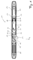
- the Fig. 1 shows a top view of a closure 10 according to the invention, which has an elongated housing 12 which accommodates the individual components of the closure 10.
- the housing 12 has two side walls 13 that are opposite one another and run in the longitudinal direction of the housing 12, between which the individual components of the closure 10, which will be described in more detail below, are arranged.
- the housing 12 has a relatively small width and depth and can therefore be mounted in a fitting groove of a sash to be secured by means of the lock 10.
- a claw-shaped closure element 14 is mounted on the housing 12 so that it can pivot about a pivot axis 15.
- the closure element 14 has a receptacle 16 in the form of a groove open on one side, the width of which is dimensioned such that a cylindrical locking element (not shown) fits into it, which is intended for attachment to the sash of the window or door.
- the housing 12 is designed for attachment to the wing and the locking element is designed for attachment to the frame.
- the closure element 14 On the side opposite the holding receptacle 16, the closure element 14 has a toothing 17 which meshes with a toothing 18 which is formed on a gear element 19 which is pivotably mounted on the housing 12 about a pivot axis 11.
- the gear element 19 On the side opposite the toothing 18, the gear element 19 forms a projection 20, also referred to here as a sliding cam, the function of which will be discussed in more detail below.
- the closure 10 has a locking carriage 21 which can be moved in the longitudinal direction thereof and which forms a locking cam 22 on the side facing the gear element 19, which interacts with the sliding cam 20, as will also be explained in more detail below.
- the closure 10 has an electric motor 23 arranged on the housing 12, which is coupled to the locking carriage 21 in such a way that it can move in different directions depending on the direction of rotation of the motor 23. More specifically, the motor 23 drives a drive spindle 24 of a spindle drive 25, with the rotation of the drive spindle 24 causing a spindle nut 26 arranged thereon is moved in a manner known per se in the longitudinal direction of the drive spindle 24.
- the locking carriage 21 is supported on the spindle nut 26 so that it can be moved in different directions together with the spindle nut 26 depending on the direction of rotation of the drive spindle 24.
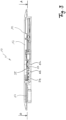
- the closure 10 has an energy storage device such as a battery arranged under a cover 27. Additionally or alternatively, the closure 10 can also have an induction coil, also located under the cover 27, via which the closure 10 can be inductively coupled to an energy source to supply energy to the electric motor 23.
- an energy storage device such as a battery arranged under a cover 27.
- the closure 10 can also have an induction coil, also located under the cover 27, via which the closure 10 can be inductively coupled to an energy source to supply energy to the electric motor 23.
- Fig. 1 can be removed in turn, the locking slide 21 is supported on the spindle nut 26 via two springs 28, so that the locking slide 21 can be deflected against the spring force of the springs 28 when the spindle nut 26 is fixed relative to the spindle nut 26.
- the spindle nut 26 can be moved relative to the locking carriage 21 when it is stationary.
- the relative mobility between the spindle nut 26 and the locking carriage 21 is limited by two stops spaced apart from one another in the axial direction of the drive spindle (not visible), so that the locking carriage 21 can be taken along by the spindle nut 26 after the respective stop has been reached.
- the two springs 28 are supported on the one hand on the locking carriage 21 and on the other hand on the spindle nut 26; Alternatively, it is also possible for the springs 28 to be supported on the one hand on the locking carriage 21 and on the other hand on a part fixed to the housing.
- FIG. 1 a position of the closure 10 in which the closure element 14 is in its release position F, in which the claw-shaped section thereof extends through an opening 29 in the housing wall 13.
- a locking element located on the sash of a window to be secured can slide into the holding receptacle 16, whereupon the closure element 14 continues to move clockwise in the direction of the closing movement of the sash Fig. 4 shown blocking position B of the closure element 14 is pivoted.
- the closure element 14 is biased towards its release position F by means of a return spring, not shown here, whereby this spring can act either directly on the closure element 14 or on the gear element 19 and thus indirectly on the closure element 14.
- the closure element 14 In the blocking position B of the closure element 14, it is angularly oriented so that the sash does not lie tightly against the frame, so that a certain amount of gap ventilation is still possible. However, the closure element 14 can be pivoted from the release position F beyond the blocking position B into a closed position in order to clamp the sash tightly to the frame.
- the locking carriage 21 is started from the one in the Fig. 4
- the locking position S shown is moved further in the direction of the gear element 19 or the closure element 14 by means of the spindle drive 25.
- the spindle nut 26 is moved in the direction of the locking carriage 21 until the spindle nut 26 abuts the locking carriage 21, so that this is moved from its locking position S towards its locking position as the spindle nut 26 continues to move.
- the sliding cam 20 continues to ride on the sliding surface 31 of the locking cam 22, with the result that the gear element 19 is pivoted further counterclockwise.
- the closure element 14 is thus turned clockwise into its position Closed position pivoted, whereby the sash is pulled firmly against the frame.
- the gear element 19 acts as a reduction gear.
- the gear element 19 can equally be replaced by a two-armed lever with lever arms of different lengths.
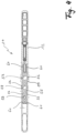
- the housing 12 forms a bearing base 50 in its interior (see Fig. 3 ) on which both the closure element 14 and the gear element 19 meshing with it are rotatably mounted, these two elements being shown in the for the sake of clarity Fig. 3 and 5 however, are not shown.
- the housing 12 is designed in its entirety as a one-piece zinc die-cast part, with the bearing base 50 being formed as an integral part of the housing 12 during the die-casting thereof.
- Three through holes 52, 53, 54 are formed in the bearing base 50 (see Fig. 3 ), whereby the through hole 52 serves to receive a pin (not shown) on which the gear element 19 is rotatably mounted, whereas the through hole 53 serves to receive a pin (not shown) on which the closure element 14 is rotatably mounted.
- the third through hole 54 serves to accommodate a screw (see Fig. 1 ), by means of which the housing 12 can be screwed into the fitting groove of a sash. The forces acting on the closure element 14 and the gear element 19 are thus transmitted to the bearing base 50 via the pins in question.
- a reinforcing plate 55 is integrated into the bearing base 50, with the reinforcing plate 55 being cast into the bearing base 50 in the embodiment shown here.
- the reinforcing plate 55 extends over essentially the entire length of the bearing base 50, so that any stresses that act on the bearing base 50 can essentially be absorbed by the reinforcing plate 55.
- the reinforcing plate 55 has an irregular lateral edge.
- the reinforcing plate 55 has several bulges and indentations 56 on its side wheels. This can ensure that the reinforcing plate 55 forms a positive connection with the material of the bearing base, whereby it can be ensured that the composite component consisting of the bearing base 50 and reinforcing plate 55 can absorb greater forces than if there is no shear-resistant connection between the reinforcing plate 55 and the bearing base 50 assists.
- the reinforcing plate 55 has three holes 57, 58, 59 corresponding to the through holes 52, 53, 54 of the bearing base 50, through which the pins, not shown here, on which the closure element 14 and the gear element 19 are rotatably mounted are, as well as those in the Fig. 1 visible fastening screw extend through.
- the opening 29 for the closure element 14 opens directly into a housing area above the bearing base 50, i.e. into the area in which the closure element 14 is mounted on the bearing base 50.
- the reinforcing plate 55 extends over this housing area into which the opening 29 opens, so that the component weakening that the housing 12 experiences through the opening 29 in the side wall 13 of the housing 12 can be at least partially compensated for by the reinforcing plate 55.
- the reinforcing plate 55 forms two tines 60 on the head and foot sides, each of these tines 60 having a support foot 61 bent out of the plane of the reinforcing plate 55 at its free end.
- the head-side support feet 61 and the foot-side support feet 61 extend in opposite directions, so that the reinforcement plate 55 can be reliably supported and held in place via the support feet 61 in a mold for the casting process of the housing 12.
- the reinforcing plate 55 forms an additional positive connection with the material of the bearing base 50, whereby a particularly shear-resistant force transmission between the reinforcing plate 55 and the bearing base 50 can be ensured.
Landscapes
- Engineering & Computer Science (AREA)
- Mechanical Engineering (AREA)
- Power-Operated Mechanisms For Wings (AREA)
- Casings For Electric Apparatus (AREA)
Claims (10)
- Fermeture (10) pour une fenêtre, une porte ou similaire, la fenêtre, la porte ou similaire comportant un cadre et un battant mobile par rapport au cadre, la fermeture comprenant :un boîtier (12) conçu pour être fixé au cadre ou au battant ; etun élément de fermeture (14) pour bloquer un élément de verrouillage fixé au battant ou au cadre, l'élément de fermeture (14) étant monté dans le boîtier (12) de façon mobile en rotation sur un socle de support (50) formé par celui-ci ;caractérisée en ce quela fermeture comprend une plaque de renforcement (55) qui est intégrée par complémentarité de forme dans le socle de support (50).
- Fermeture selon la revendication 1,
dans laquelle le boîtier (12) est réalisé d'un seul tenant sous forme de pièce métallique coulée, et la plaque de renforcement (55) est intégrée par coulée dans le socle de support (50). - Fermeture selon la revendication 1 ou 2,
dans laquelle la plaque de renforcement (55) est bordée au moins localement de manière irrégulière. - Fermeture selon l'une des revendications précédentes,
dans laquelle le boîtier (12) est fabriqué en un premier matériau métallique, et la plaque de renforcement (55) est fabriquée en un deuxième matériau métallique, le deuxième matériau métallique présentant une tendance à la rupture fragile inférieure à celle du premier matériau métallique, et/ou le deuxième matériau métallique présentant une ductilité et/ou une ténacité supérieure à celle du premier matériau métallique. - Fermeture selon l'une des revendications précédentes,
dans laquelle le boîtier (12) est une pièce coulée sous pression en un alliage de zinc, d'aluminium ou de magnésium, et la plaque de renforcement (55) est fabriquée en acier, en particulier en acier au chrome, de préférence en X14CrMoS17. - Fermeture selon l'une des revendications précédentes,
dans laquelle en outre un élément de transmission (19), en particulier une roue dentée à denture au moins partielle ou un levier de préférence à deux bras, est monté sur le socle de support (50) de façon mobile en rotation et est en prise d'entraînement avec l'élément de fermeture (14). - Fermeture selon l'une des revendications précédentes,dans laquelle l'élément de fermeture (14) est monté de façon mobile en rotation sur un premier pivot qui est au moins partiellement reçu par le socle de support (50) et qui s'étend à travers la plaque de renforcement (55), et/oul'élément de transmission (19) est monté de façon mobile en rotation sur un deuxième pivot qui est au moins partiellement reçu par le socle de support (50) et qui s'étend à travers la plaque de renforcement (55).
- Fermeture selon l'une des revendications précédentes,
dans laquelle le boîtier (12) comprend une paroi latérale (13) dans laquelle est ménagée une ouverture (29) pour l'élément de fermeture (14), l'ouverture (29) débouchant directement dans une zone du boîtier située au-dessus du socle de support (50). - Fermeture selon la revendication 8,
dans laquelle la plaque de renforcement (55) dans le socle de support (50) s'étend au-delà de la zone du boîtier dans laquelle débouche l'ouverture (29). - Fermeture selon l'une des revendications précédentes,
dans laquelle la plaque de renforcement (55) comporte plusieurs pieds d'appui (61) qui sont pliés hors du plan de la plaque de renforcement (55) et qui sont intégrés par coulée dans le socle de support (50).
Applications Claiming Priority (2)
| Application Number | Priority Date | Filing Date | Title |
|---|---|---|---|
| DE102019117867.3A DE102019117867A1 (de) | 2019-07-02 | 2019-07-02 | Verschluss mit einem verstärkten gehäuse für ein fenster, eine tür oder dergleichen |
| PCT/EP2020/068408 WO2021001372A1 (fr) | 2019-07-02 | 2020-06-30 | Serrure dotée d'un boîtier renforcé pour une fenêtre, une porte ou similaire |
Publications (2)
| Publication Number | Publication Date |
|---|---|
| EP3963151A1 EP3963151A1 (fr) | 2022-03-09 |
| EP3963151B1 true EP3963151B1 (fr) | 2023-11-15 |
Family
ID=71527763
Family Applications (1)
| Application Number | Title | Priority Date | Filing Date |
|---|---|---|---|
| EP20737391.1A Active EP3963151B1 (fr) | 2019-07-02 | 2020-06-30 | Serrure dotée d'un boîtier renforcé pour une fenêtre, une porte ou similaire |
Country Status (5)
| Country | Link |
|---|---|
| EP (1) | EP3963151B1 (fr) |
| CN (1) | CN114096727B (fr) |
| DE (1) | DE102019117867A1 (fr) |
| PL (1) | PL3963151T3 (fr) |
| WO (1) | WO2021001372A1 (fr) |
Family Cites Families (11)
| Publication number | Priority date | Publication date | Assignee | Title |
|---|---|---|---|---|
| DE1048507B (de) * | 1959-06-11 | Oslo Daniel Martens | Riegelfall'enschloß | |
| AT384649B (de) * | 1985-04-17 | 1987-12-10 | Mayer & Co Riegel Beschlag | Feststellvorrichtung fuer einen fenster- oder tuerfluegel in wenigstens einer spaltlueftungsstellung |
| DE29805358U1 (de) * | 1998-03-25 | 1999-07-29 | Ramsauer | Schnappverschluß für eine Blechschrankschiebetür |
| FR2791386B1 (fr) * | 1999-03-23 | 2001-06-08 | Valeo Securite Habitacle | Serrure pour ouvrant de vehicule automobile |
| PT1118739E (pt) * | 2000-01-21 | 2005-08-31 | Talpe Joseph Jr | Fechadura |
| NL1033325C2 (nl) * | 2007-02-02 | 2008-08-05 | M H B B V | Vergrendelingsinrichting en samenstel. |
| DE202014000876U1 (de) * | 2014-02-03 | 2015-05-05 | Siegenia-Aubi Kg | Beschlag eines zumindest hebbaren, vorzugsweise aber auch verschiebbaren Flügels von Fenstern oder Türen |
| DE102015112261A1 (de) * | 2015-07-28 | 2017-02-02 | Maco Technologie Gmbh | Verschluss für ein Fenster, eine Tür oder dergleichen |
| DE102015112256A1 (de) * | 2015-07-28 | 2017-02-02 | Maco Technologie Gmbh | Verschluss für ein Fenster, eine Tür oder dergleichen |
| DE102016104596A1 (de) * | 2016-03-14 | 2017-09-14 | Maco Technologie Gmbh | Beschlaganordnung zur Sicherung eines Fensters, einer Tür oder dergleichen an einem Schließblech |
| DE102017104152A1 (de) * | 2017-02-28 | 2018-08-30 | Kiekert Ag | Kraftfahrzeugtürschloss |
-
2019
- 2019-07-02 DE DE102019117867.3A patent/DE102019117867A1/de active Pending
-
2020
- 2020-06-30 EP EP20737391.1A patent/EP3963151B1/fr active Active
- 2020-06-30 PL PL20737391.1T patent/PL3963151T3/pl unknown
- 2020-06-30 CN CN202080048972.1A patent/CN114096727B/zh active Active
- 2020-06-30 WO PCT/EP2020/068408 patent/WO2021001372A1/fr unknown
Also Published As
| Publication number | Publication date |
|---|---|
| EP3963151A1 (fr) | 2022-03-09 |
| DE102019117867A1 (de) | 2021-01-07 |
| CN114096727A (zh) | 2022-02-25 |
| PL3963151T3 (pl) | 2024-04-15 |
| CN114096727B (zh) | 2024-03-19 |
| WO2021001372A1 (fr) | 2021-01-07 |
Similar Documents
| Publication | Publication Date | Title |
|---|---|---|
| DE102007035116A1 (de) | Gelenkstabschloss | |
| EP2692969B1 (fr) | Engrenage d'un dispositif de verrouillage à crémone, dispositif de verrouillage avec un tel engrenage ainsi que fenêtre, porte ou analogue avec un tel dispositif de verrouillage à crémone | |
| EP2362041B1 (fr) | Verrouillage de protection contre les mines pour l'agencement sur des portes de véhicules militaires | |
| EP0007395A1 (fr) | Serrure pour portes à serrure cylindrique actionnée par une clé | |
| DE202013009352U1 (de) | Fenster oder Tür mit einem Beschlag | |
| EP2929113B1 (fr) | Serrure pour une coffre ou une porte | |
| DE202005000939U1 (de) | Verriegelungseinrichtung | |
| EP3963151B1 (fr) | Serrure dotée d'un boîtier renforcé pour une fenêtre, une porte ou similaire | |
| EP2784248B1 (fr) | Agencement d'engrenage pour une ferrure de bielle | |
| EP3266960A1 (fr) | Système comprenant un châssis dormant destiné à loger un cadre de vantail | |
| EP3655601B1 (fr) | Serrure | |
| DE19831142B4 (de) | Treibstangenbeschlag für einen Reinigungsflügel | |
| EP2453086B1 (fr) | Ferrure de crémone pour battant fixe de fenêtres ou de portes à deux vantaux sans montant médian | |
| AT509464B1 (de) | Schloss | |
| DE202018103048U1 (de) | Schloss | |
| EP2320013B1 (fr) | Armature dotée d'une transmission de renvoi | |
| WO2012119721A2 (fr) | Serrure de meuble | |
| EP3222801A1 (fr) | Verrou pour coffres-forts | |
| DE10318707B4 (de) | Sicherheitseinrichtung | |
| DE102007035123B4 (de) | Kippsicherung | |
| DE102006031226B4 (de) | Schloss für eine Fahrzeugtür | |
| EP1361327B1 (fr) | Ferrure | |
| DE102016122551A1 (de) | Flügelrahmen eines Fensters oder einer Tür | |
| DE60025126T2 (de) | Schlossmechanismus für Fahrzeugtüre | |
| EP1359270B1 (fr) | Caisse de gâche pour cadres en acier |
Legal Events
| Date | Code | Title | Description |
|---|---|---|---|
| STAA | Information on the status of an ep patent application or granted ep patent |
Free format text: STATUS: UNKNOWN |
|
| STAA | Information on the status of an ep patent application or granted ep patent |
Free format text: STATUS: THE INTERNATIONAL PUBLICATION HAS BEEN MADE |
|
| PUAI | Public reference made under article 153(3) epc to a published international application that has entered the european phase |
Free format text: ORIGINAL CODE: 0009012 |
|
| STAA | Information on the status of an ep patent application or granted ep patent |
Free format text: STATUS: REQUEST FOR EXAMINATION WAS MADE |
|
| 17P | Request for examination filed |
Effective date: 20211129 |
|
| AK | Designated contracting states |
Kind code of ref document: A1 Designated state(s): AL AT BE BG CH CY CZ DE DK EE ES FI FR GB GR HR HU IE IS IT LI LT LU LV MC MK MT NL NO PL PT RO RS SE SI SK SM TR |
|
| DAV | Request for validation of the european patent (deleted) | ||
| DAX | Request for extension of the european patent (deleted) | ||
| GRAP | Despatch of communication of intention to grant a patent |
Free format text: ORIGINAL CODE: EPIDOSNIGR1 |
|
| STAA | Information on the status of an ep patent application or granted ep patent |
Free format text: STATUS: GRANT OF PATENT IS INTENDED |
|
| INTG | Intention to grant announced |
Effective date: 20230531 |
|
| GRAS | Grant fee paid |
Free format text: ORIGINAL CODE: EPIDOSNIGR3 |
|
| GRAA | (expected) grant |
Free format text: ORIGINAL CODE: 0009210 |
|
| STAA | Information on the status of an ep patent application or granted ep patent |
Free format text: STATUS: THE PATENT HAS BEEN GRANTED |
|
| AK | Designated contracting states |
Kind code of ref document: B1 Designated state(s): AL AT BE BG CH CY CZ DE DK EE ES FI FR GB GR HR HU IE IS IT LI LT LU LV MC MK MT NL NO PL PT RO RS SE SI SK SM TR |
|
| REG | Reference to a national code |
Ref country code: CH Ref legal event code: EP Ref country code: GB Ref legal event code: FG4D Free format text: NOT ENGLISH |
|
| REG | Reference to a national code |
Ref country code: DE Ref legal event code: R096 Ref document number: 502020006056 Country of ref document: DE |
|
| REG | Reference to a national code |
Ref country code: IE Ref legal event code: FG4D Free format text: LANGUAGE OF EP DOCUMENT: GERMAN |
|
| P01 | Opt-out of the competence of the unified patent court (upc) registered |
Effective date: 20231102 |
|
| REG | Reference to a national code |
Ref country code: NL Ref legal event code: FP |
|
| REG | Reference to a national code |
Ref country code: LT Ref legal event code: MG9D |
|
| PG25 | Lapsed in a contracting state [announced via postgrant information from national office to epo] |
Ref country code: GR Free format text: LAPSE BECAUSE OF FAILURE TO SUBMIT A TRANSLATION OF THE DESCRIPTION OR TO PAY THE FEE WITHIN THE PRESCRIBED TIME-LIMIT Effective date: 20240216 |
|
| PG25 | Lapsed in a contracting state [announced via postgrant information from national office to epo] |
Ref country code: IS Free format text: LAPSE BECAUSE OF FAILURE TO SUBMIT A TRANSLATION OF THE DESCRIPTION OR TO PAY THE FEE WITHIN THE PRESCRIBED TIME-LIMIT Effective date: 20240315 |
|
| PG25 | Lapsed in a contracting state [announced via postgrant information from national office to epo] |
Ref country code: LT Free format text: LAPSE BECAUSE OF FAILURE TO SUBMIT A TRANSLATION OF THE DESCRIPTION OR TO PAY THE FEE WITHIN THE PRESCRIBED TIME-LIMIT Effective date: 20231115 |
|
| PG25 | Lapsed in a contracting state [announced via postgrant information from national office to epo] |
Ref country code: ES Free format text: LAPSE BECAUSE OF FAILURE TO SUBMIT A TRANSLATION OF THE DESCRIPTION OR TO PAY THE FEE WITHIN THE PRESCRIBED TIME-LIMIT Effective date: 20231115 |
|
| PG25 | Lapsed in a contracting state [announced via postgrant information from national office to epo] |
Ref country code: LT Free format text: LAPSE BECAUSE OF FAILURE TO SUBMIT A TRANSLATION OF THE DESCRIPTION OR TO PAY THE FEE WITHIN THE PRESCRIBED TIME-LIMIT Effective date: 20231115 Ref country code: IS Free format text: LAPSE BECAUSE OF FAILURE TO SUBMIT A TRANSLATION OF THE DESCRIPTION OR TO PAY THE FEE WITHIN THE PRESCRIBED TIME-LIMIT Effective date: 20240315 Ref country code: GR Free format text: LAPSE BECAUSE OF FAILURE TO SUBMIT A TRANSLATION OF THE DESCRIPTION OR TO PAY THE FEE WITHIN THE PRESCRIBED TIME-LIMIT Effective date: 20240216 Ref country code: ES Free format text: LAPSE BECAUSE OF FAILURE TO SUBMIT A TRANSLATION OF THE DESCRIPTION OR TO PAY THE FEE WITHIN THE PRESCRIBED TIME-LIMIT Effective date: 20231115 Ref country code: BG Free format text: LAPSE BECAUSE OF FAILURE TO SUBMIT A TRANSLATION OF THE DESCRIPTION OR TO PAY THE FEE WITHIN THE PRESCRIBED TIME-LIMIT Effective date: 20240215 Ref country code: PT Free format text: LAPSE BECAUSE OF FAILURE TO SUBMIT A TRANSLATION OF THE DESCRIPTION OR TO PAY THE FEE WITHIN THE PRESCRIBED TIME-LIMIT Effective date: 20240315 |