EP3962059B1 - Kameramodul - Google Patents
Kameramodul Download PDFInfo
- Publication number
- EP3962059B1 EP3962059B1 EP21196055.4A EP21196055A EP3962059B1 EP 3962059 B1 EP3962059 B1 EP 3962059B1 EP 21196055 A EP21196055 A EP 21196055A EP 3962059 B1 EP3962059 B1 EP 3962059B1
- Authority
- EP
- European Patent Office
- Prior art keywords
- protrusion
- substrate
- disposed
- camera module
- connector
- Prior art date
- Legal status (The legal status is an assumption and is not a legal conclusion. Google has not performed a legal analysis and makes no representation as to the accuracy of the status listed.)
- Active
Links
Images








Classifications
-
- G—PHYSICS
- G03—PHOTOGRAPHY; CINEMATOGRAPHY; ANALOGOUS TECHNIQUES USING WAVES OTHER THAN OPTICAL WAVES; ELECTROGRAPHY; HOLOGRAPHY
- G03B—APPARATUS OR ARRANGEMENTS FOR TAKING PHOTOGRAPHS OR FOR PROJECTING OR VIEWING THEM; APPARATUS OR ARRANGEMENTS EMPLOYING ANALOGOUS TECHNIQUES USING WAVES OTHER THAN OPTICAL WAVES; ACCESSORIES THEREFOR
- G03B17/00—Details of cameras or camera bodies; Accessories therefor
- G03B17/02—Bodies
-
- G—PHYSICS
- G03—PHOTOGRAPHY; CINEMATOGRAPHY; ANALOGOUS TECHNIQUES USING WAVES OTHER THAN OPTICAL WAVES; ELECTROGRAPHY; HOLOGRAPHY
- G03B—APPARATUS OR ARRANGEMENTS FOR TAKING PHOTOGRAPHS OR FOR PROJECTING OR VIEWING THEM; APPARATUS OR ARRANGEMENTS EMPLOYING ANALOGOUS TECHNIQUES USING WAVES OTHER THAN OPTICAL WAVES; ACCESSORIES THEREFOR
- G03B17/00—Details of cameras or camera bodies; Accessories therefor
- G03B17/02—Bodies
- G03B17/08—Waterproof bodies or housings
-
- G—PHYSICS
- G03—PHOTOGRAPHY; CINEMATOGRAPHY; ANALOGOUS TECHNIQUES USING WAVES OTHER THAN OPTICAL WAVES; ELECTROGRAPHY; HOLOGRAPHY
- G03B—APPARATUS OR ARRANGEMENTS FOR TAKING PHOTOGRAPHS OR FOR PROJECTING OR VIEWING THEM; APPARATUS OR ARRANGEMENTS EMPLOYING ANALOGOUS TECHNIQUES USING WAVES OTHER THAN OPTICAL WAVES; ACCESSORIES THEREFOR
- G03B17/00—Details of cameras or camera bodies; Accessories therefor
- G03B17/02—Bodies
- G03B17/12—Bodies with means for supporting objectives, supplementary lenses, filters, masks, or turrets
-
- G—PHYSICS
- G03—PHOTOGRAPHY; CINEMATOGRAPHY; ANALOGOUS TECHNIQUES USING WAVES OTHER THAN OPTICAL WAVES; ELECTROGRAPHY; HOLOGRAPHY
- G03B—APPARATUS OR ARRANGEMENTS FOR TAKING PHOTOGRAPHS OR FOR PROJECTING OR VIEWING THEM; APPARATUS OR ARRANGEMENTS EMPLOYING ANALOGOUS TECHNIQUES USING WAVES OTHER THAN OPTICAL WAVES; ACCESSORIES THEREFOR
- G03B30/00—Camera modules comprising integrated lens units and imaging units, specially adapted for being embedded in other devices, e.g. mobile phones or vehicles
-
- H—ELECTRICITY
- H04—ELECTRIC COMMUNICATION TECHNIQUE
- H04N—PICTORIAL COMMUNICATION, e.g. TELEVISION
- H04N23/00—Cameras or camera modules comprising electronic image sensors; Control thereof
- H04N23/50—Constructional details
- H04N23/51—Housings
-
- H—ELECTRICITY
- H04—ELECTRIC COMMUNICATION TECHNIQUE
- H04N—PICTORIAL COMMUNICATION, e.g. TELEVISION
- H04N23/00—Cameras or camera modules comprising electronic image sensors; Control thereof
- H04N23/50—Constructional details
- H04N23/52—Elements optimising image sensor operation, e.g. for electromagnetic interference [EMI] protection or temperature control by heat transfer or cooling elements
-
- H—ELECTRICITY
- H04—ELECTRIC COMMUNICATION TECHNIQUE
- H04N—PICTORIAL COMMUNICATION, e.g. TELEVISION
- H04N23/00—Cameras or camera modules comprising electronic image sensors; Control thereof
- H04N23/50—Constructional details
- H04N23/54—Mounting of pick-up tubes, electronic image sensors, deviation or focusing coils
-
- H—ELECTRICITY
- H04—ELECTRIC COMMUNICATION TECHNIQUE
- H04N—PICTORIAL COMMUNICATION, e.g. TELEVISION
- H04N23/00—Cameras or camera modules comprising electronic image sensors; Control thereof
- H04N23/50—Constructional details
- H04N23/55—Optical parts specially adapted for electronic image sensors; Mounting thereof
-
- H—ELECTRICITY
- H04—ELECTRIC COMMUNICATION TECHNIQUE
- H04N—PICTORIAL COMMUNICATION, e.g. TELEVISION
- H04N23/00—Cameras or camera modules comprising electronic image sensors; Control thereof
- H04N23/57—Mechanical or electrical details of cameras or camera modules specially adapted for being embedded in other devices
Definitions
- the teachings in accordance with exemplary and non-limiting embodiments of this invention relate generally to a camera module.
- the camera module capturing a subject in a photograph or an image may be mounted on various devices and pieces of equipment. Inter alia, vehicles mounted with camera modules have been marketed. The camera module may be used on a vehicle as front and rear monitoring cameras, blackboxes and the like.
- a structure is required to mount a camera module when the camera module is to be mounted on a vehicle. Furthermore, a solid strong sealing is required in case of assembling parts to thereby prevent foreign objects from being introduced into the camera module, because a part of the camera module is exposed outside of the vehicle when mounted on a vehicle.
- a camera module mounted on a vehicle is disposed therein with a plurality of substrates, where a structure is also required to fix the plurality of substrates inside the camera module while being discretely diposed.
- a structure is further required to fix a connector extended from a substrate and shielding electromagnetic waves generated from inside the camera module.
- the exemplary embodiment of the present invention is to provide a camera module including a coupling structure (bracket) in order to mount a camera module on a vehicle.
- Another example is a camera module coupled to a vehicle in a solid sealing structure.
- the exemplary embodiment of the present invention is further to provide a camera module including a structure supporting a plurality of substrates in a discrete state.
- Another example is a camera module including a cover fixing a connector extended from a substrate and shielding electromagnetic waves generated from inside of the camera module.
- a camera module according to the present invention is claimed in claim 1.
- Preferred embodiments of the camera module according to the present invention are claimed in claims 2 to 14.
- the pressing part may include a first pressing part diposed to a first direction and a second pressing part disposed to a second direction different from the first direction.
- the first direction may be perpendicular to the second direction.
- the protrusion may include first and second protrusion each spaced apart on the second surface of the rear body, and the hook may include a first hook hitched by the first protrusion and a second hook hitched by the second protrusion, and the rear body may further include a rib diposed between the first hook and the second hook, and a width of the rib may correspond to a discrete distance between the first hook and the second hook.
- An outer surface of rear body may further include a third surface disposed opposite to the second surface
- the protrusion may include a first protrusion disposed on a second surface of rear body and a second protrusion disposed on a third surface of the rear body
- the hook may include a first hook hitched by the first protrusion and a second hook hitched by the second protrusion.
- the pressing part may include a first extension part integrally formed with the bottom part, and extended from the bottom part toward a first surface of the rear body, and a contact part extended from the first extension part to contact a first surface of the rear body, and a second extension part extended from the contact part toward a direction distancing from the first surface of the rear body.
- the camera module may further comprise a connector extended from the second substrate to pass through the rear body, and the bottom part of the bracket may include a hole passed through by the connector.
- the second protrusion may include a bottom part spaced apart from an outer circumference of the first surface of the front body, and the rear body may include a bottom part spaced apart from the front body, and a side part extended from the bottom part toward the front body, wherein the side part of the rear body may include a second surface facing the front body, a second protrusion protruded from the second surface, a third protrusion protrused from the second surface and disposed at a position corresponding to that between the second protrusion and the outer circumference of the first surface at the front body, and a fourth protrusion slantly connecting an inner surface of the third protrusion and the second surface, and the front body and the rear body may be coupled by allowing the second protrusion and the fourth protrusion to be fused.
- the second protrusion of the front body and the fourth protrusion of the rear body may be integrated by ultrasonic fusion.
- a distance between a distal end of the first protrusion and the first surface is longer than a distance between a distal end of the second protrusion and the first surface
- the rib is extended from the first surface of front body, the rib includes a slant surface so slanted as to allow a distance at the first protrusion between a distal end of the rib and the first surface is formed to be longer than a distance at the second protrusion between a distal end of the rib and the first surface.
- the substrate may include a third surface facing the front body, and a distal surface of the first protrusion may be fixed to the third surface of the substrate by an adhesive.
- Size of an outer circumference at the first protrusion may be smaller than size of an outer circumference of the third surface at the substrate.
- the rear body may include a groove disposed at an outer circumference of the third protrusion and extended to a distal end of the third protrusion.
- the lens, the barrel and the front body may be integrally formed.
- Each of the first protrusion and the second protrusion is extended from the first surface so as to allow a cross-section to form a single closed curve shape.
- At least two surfaces of the four surfaces of the protrusion may be spaced apart from the extension part.
- the camera module may further comprise a cover fixed to an inner surface of rear body, wherein the cover may include a bottom plate including a hole passed through by the connector, and a side plate extended from the bottom plate, and the bottom plate of the cover may include a pressing unit elastically support the connector.
- the first substrate may include a third surface facing the second substrate, and the shield member may include a protrusion coupled to the third surface of the first substrate.
- the shield member may further include a first slant part outwardly slantly extended from the extension part, and a second slant part inwardly slantly extended from the first slant part.
- the body part may be formed with four (4) pieces, each spaced apart, and may further include four (4) connection parts connecting the four body parts.
- the second substrate may include three protrusions
- the shield member may include three extension parts respectively coupled to the three protrusions.
- the extension part may be extended from four surfaces of the shield member, each of the three body parts out of the four body parts of the shield member may be disposed with an extension part, and the remaining body part may be disposed with a cut-out part, and the cut-out part may be more recessed than the fourth surface, and a groove may be disposed between the cut-out part and the fourth surface.
- the first pressing unit and the second pressing unit may be integrally formed with the bottom plate.
- the pressing unit may include a first extension part inwardly slantly extended from the bottom plate, and a first contact part extended from the first extension part to contact a first surface of the connector, and a second extension part slantly extended toward the hole from the first contact part.
- the pressing unit may further include a second contact part extended from the second extension part to contact a second surface of connector, and a third extension part slantly outwardly extended from the second contact part.
- a distal end of the side plate may be overlapped with the first substrate to a direction perpendicular to an optical axis of the lens.
- the pressing unit may include four (4) pressing pieces, each spaced apart from the other, and the said four pressing pieces may be equidistantly disposed on a circumference of second surface of connector.
- the camera module may further include a shield member coupled to the first substrate and the second substrate, and the shield member may include a body part coupled to the first substrate, a coupling part extended from the body part and coupled to the second substrate, and the coupling part may be contacted to the side plate of cover.
- An external surface of cover and the connector may be grounded.
- the exemplary embodiment has an advantageous effect in that a rear body and a bracket of a camera module can be easily assembled to be conducive to improvement of manufacturing yield.
- the exemplary embodiment has an advantageous effect in that the phenomenon of foreign objects and moisture outside of camera module being introduced into the camera module can be prevented.
- the exemplary embodiment has an advantageous effect in that a support structure comprising a plurality of substrates is provided to thereby contribute to miniaturization of camera module.
- the exemplary embodiment has an advantageous effect in that a reduced manufacturing cost can be expected by performing shield of electromagnetic wave and fixture of connector through a cover of relatively simple structure.
- first, second, A, B (a), (b), etc. may be used. These terms may be used only to distinguish one element from another element, and the nature, order or sequence is not restricted by these terms.
- any one of “inner protrusion(132)”, “outer protrusion (133)”, “external wall protrusion (221)” and “fusion protrusion (222)” may be called a “first protrusion”, a remaining one may be called a “second protrusion”, another remaining one may be called a “third protrusion” and the remaining one may be called a “fourth protrusion”.
- any one of a “rib (134)” and a “rib (225)” may be called a “first rib” and the remaining one may be called a “second rib”.
- any one of a “front substrate (310)” and a “rear substrate (320)” may be called a “first substrate” and the remaining one may be called a “second substrate”.
- any one of a “guide groove (345a)” and a “discrete groove (345b)” may be called a “first groove” and the remaining one may be called a “second groove”.
- FIG. 1 is a perspective view of a camera module according to an exemplary embodiment of the present invention
- FIG. 2 is a perspective view of a camera module viewed from a different direction of FIG. 1 according to an exemplary embodiment of the present invention
- FIG. 3 is an exploded perspective view of a camera module according to an exemplary embodiment of the present invention
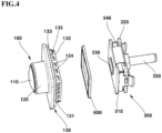
- FIG. 4 is an exploded perspective view of some elements of a camera module according to an exemplary embodiment of the present invention
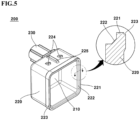
- FIG. 5 is a perspective view and a partially enlarged view of a rear body of a camera module according to an exemplary embodiment of the present invention
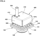
- FIG. 6 is a perspective view of some elements of a camera module according to an exemplary embodiment of the present invention
- FIG. 1 is a perspective view of a camera module according to an exemplary embodiment of the present invention
- FIG. 2 is a perspective view of a camera module viewed from a different direction of FIG. 1 according to an exemplary embodiment of the present invention
- FIG. 3 is an exploded perspective view of a
- FIG. 7 is a perspective view and a partially enlarged view of some elements of a camera module according to an exemplary embodiment of the present invention
- FIG. 8 is a perspective view illustrating a state of a process in which some elements of camera module are assembled according to an exemplary embodiment of the present invention
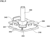
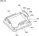
- FIGS. 9 and 10 are perspective views of some elements of a camera module according to an exemplary embodiment of the present invention
- FIG. 11 is a planar view of a shield member of a camera module according to an exemplary embodiment of the present invention
- FIG. 12 is a perspective view illustrating a state of a process in which a shield member of a camera module is assembled according to an exemplary embodiment of the present invention
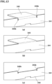
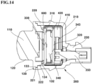
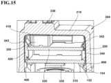
- FIG. 13 is a perspective view of some elements of a shield member in a camera module, where FIG. 13(a) illustrates a configuration related to a bar of a shield member according to an exemplary embodiment (first exemplary embodiment), FIG. 13(b) illustrates a configuration related to a bar of a shield member according to a modification (second exemplary embodiment), and FIG. 13 (c) illustrates a state where a bar of a shield member is removed according to an exemplary embodiment (first exemplary embodiment), FIG. 14 is a cross-sectional view of a camera module according to an exemplary embodiment of the present invention, FIGS. 15 and 16 are cross-sectional perspective views of some elements of a camera module according to an exemplary embodiment of the present invention, FIG.
- FIG. 17 is a perspective view of a camera module according to an exemplary embodiment of the present invention
- FIG. 18 is a perspective view of some elements of a camera module according to an exemplary embodiment of the present invention
- FIG. 19 is a planar view in a manufacturing process of a shield member according to an exemplary embodiment of the present invention
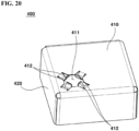
- FIG. 20 is a perspective view of a cover according to an exemplary embodiment of the present invention.
- a camera module may be coupled to a vehicle.
- the camera module may be used for any one or more of a front camera of a vehicle, a side camera, a rear camera and a blackbox camera.
- the camera module may capture a subject and output the captured subject in an image to a display part (not shown).
- the camera module may include a front body assembly (100).
- the front body assembly (100) may include a lens (110), a barrel (120) and a front body (130).
- the lens (110), the barrel (120) and the front body (130) may be integrally formed in the present exemplary embodiment.
- the lens (110), the barrel (120) and the front body (130) may omit an additional sealing member supposedly disposed among a lens (110), a barrel (120) and a front body (130) essentially required over a comparative illustration where the lens (110), the barrel (120) and the front body (130) are not integrally formed.
- more than two elements of the lens (110), the barrel (120) and the front body (130) may be integrally formed.
- the front body assembly (100) may include a lens (110).
- the front body assembly (100) may include a plurality of lenses (110).
- the lens (110) may be disposed on the barrel (120).
- the lens (110) may be accommodated into the barrel (120).
- the lens (110) may be formed in a plural number.
- the lens (110) may be aligned with an image sensor (330). That is, an opitical axis of lens (110) and an optical axis of image sensor (330) may be matchingly aligned.
- the front body assembly (100) may include an IR filter (Infrared Ray filter) disposed on a rear side of the lens (110).
- IR filter Infrared Ray filter
- the front body assembly (100) may include a barrel (120).
- the barrel (120) may be disposed on the front body assembly (130).
- the barrel (120) may accommodate the lens (110) therein.
- An inner circumferential surface of the barrel (120) may be formed with a shape and a size corresponding to those of an outer circumferential surface of the plurality of lenses (110).
- the front body assembly (100) may include a front body (130).
- the front body (130) may be coupled by the barrel (120).
- the front body (130) may be coupled with a rear body (200).
- the front body (130) may be coupled with a front substrate (310).
- the front substrate (310) is coupled with the barrel (120).
- the front body (130) may include a body part (131).
- the body part (131) may be outwardly extended from an outer circumferential surface of barrel (120).
- the outer circumferential surface of body part (131) may include a squared four-angled shape. However, corners on the outer circumferential surface of the body part (131) may be roundly formed.
- the body part (131) may include a rear surface (hereinafter referred to as "first surface") facing the front substrate (310).
- the front body (130) includes a first surface (rear surface) facing the rear body (200), an inner protrusion protruded from the first surface and spaced apart from the first surface (132, hereinafter referred to as first protrusion") and an outer protrusion (133, hereinafter referred to as "second protrusion").
- the front body (130) includes an inner protrusion (132).
- the inner protrusion (132) may be protruded from a first surface of the body part (131) of front body (130).
- the inner protrusion (132) is disposed inside of the outer protrusion (133).
- the inner protrusion (132) is coupled with the front substrate (310).
- a distance between a distal end of the inner protrusion (132) and a first surface of body part (131) is longer than a distance between a distal end of outer protrusion (133) and a first surface of the body part (131). That is, the inner protrusion (132) is more protruded than the outer protrusion (133).
- a distal surface of the inner protrusion (132) may be fixed to a third surface (front surface)) of front substrate (310) by an adhesive.
- the size of a distal surface of inner protrusion (132) may be smaller than that of an outer circumference of the third surface (front surface) of the front substrate (310).
- the adhesive (600) is disposed at an inner side from an outer circumference of front substrate by being spaced apart in the present exemplary embodiment, the phenomenon of adhesive (600) being discharged to outside of the front substrate (310) can be prevented.
- the inner protrusion (132) may be extended from the first surface of the body part (131) to allow having a single closed curved shape at a cross-section thereof.
- the outer circumferrnece of inner protrusion (132) may include a four-angled square shape. However, corners of the outer circumference in the inner protrusion (132) may be roundly formed.
- the front body (130) includes an outer protrusion (133).
- the outer protrusion (133) protrudes from a first surface of the body part (131) of front body (130).
- the outer protrusion (133) is disposed outside of the inner protrusion (132).
- the outer protrusion (133) is coupled with the rear body (200).
- the outer protrusion (133) may be spaced apart from an an outer circumference of first surface of body part (131) at the front body (130).
- the outer protrusion (133) may be disposed between the inner protrusion (132) and the outer circumference of body part (131).
- the outer protrusion (133) is extended from the first surface of the body part (131) to allowing having a single closed curved shape at a cross-section.
- the outer circumference of the outer protrusion (133) may include a four-angled square shape. However, corners of the outer circumference of the outer protrusion (133) may be roundly formed.
- the front body (130) in the present exemplary embodiment includes a plurality of ribs (134) to connect the inner protrusion (132) and the outer protrusion (133) between the inner protrusion (132) and the outer protrusion (133) and to be mutually spaced apart.
- a plurality of discrete space (135) may be formed among the plurality of ribs (134).
- the thus-described discrete structure of the plurality of ribs (134) may be called a "weight-loss structure".
- the discrete structure of the plurality of ribs (134) in the present exemplary embodiment can minimize the phenomenon of heat generated from an ultrasonic fusiong process between the front body (130) and the rear body (200) from being transmitted to an adhesive (600) that fixes the inner protrusion (132) of front body (130) to the front substrate (310).
- the front body (130) may includes a rib (134).
- the rib (134) is extended from a first surface of body part (131) at the front body (130).
- the rib (134) may connect the inner protrusion (132) with the outer protrusion (133).
- the rib (134) can reinforce the strength of the inner protrusion (132) and the outer protrusion (133).
- the rib (134) is disposed in a plural number, each mutually spaced apart. At this time, a plurality of discrete spaces (135) may be formed among the plurality of ribs (134).
- the rib (134) may be disposed, five (5) ribs each, on four surfaces of inner protrusion (132).
- the rib (134) may be spaced apart from corners of the inner protrusion (132).
- the rib (134) includes an inclined slant surface (134a).
- the rib (134) includes a slant surface (134a) so that a distance between a distal end of the rib (134) and a first surface of body part (131) at the inner protrusion (132) side is longer than a distance between a distal end of rib (134) and a first surface of body part (131) at the outer protrusion (133) side.
- the distal surface of rib (1340 in the present exemplary embodiment is slantly disposed relative to the inner protrusion (132) and the outer protrusion (133). At this time, the slant is such that the height of the rib (134) is decreased toward an outside.
- the slant surface (134a) guides the insertion of front body (130) when the front body (130) is inserted into an inner space of rear body (200).
- the front body (130) may include a discrete space (135).
- the discrete space (135) may be disposed among the plurality of ribs (134).
- the discrete space may prevent the phenomenon in which heat generated from the outer protrusion (133) reaches the adhesive (600) disposed inside of the inner protrusion (132) through the discrete space (135) at the time of ultrasonic coupling (fusion).
- the camera module may include a rear body (200).
- the rear body (200) may be coupled with the front body (130).
- the rear body (200) may form a space thereinside through the coupling with the front body (130).
- the front body (130) and the rear body (200) in the present exemplary embodiment may be coupled by allowing the outer protrusion (133) and a fusion protrusion (222) to be fused.
- the outer protrusion (133) of front body (130) and the fusion protrusion (222) of rear body (200) may be integrated by the ultrasonic fusion.
- the ultrasonic fusion between the rear body (200) and the front body (130) may mean a process in which the rear body (200) and the front body (130) are fused and integrated at a contact area while the front body is pressed and vibrated at the same time while the rear body (200) is fixed.
- the fusion protrusion (222) of rear body (200) and an outer protrusion (133) of front body (130) may be integrated by fusion through generation of high temperature.
- the front body (130) may be fixed and the rear body (200) is pressed and simultaneously vibrated at the time of ultrasonic fusion.
- the ultrasonic fusion in the present exemplary embodiment may be called a "ultrasonic fusion", a “pressure/vibration fusion” and the like.
- the rear body (200) may include a bottom part (210) spaced apart from the front body (130), and a side part (220) extended from the bottom part (210) toward the front body (130).
- the rear body (200) may include a bottom part (210).
- the bottom part (210) may be spaced apart from the front body (130).
- the bottom part (210) may be so disposed as to be parallel with the front body (130).
- the bottom part (210) may take a four-angled plate shape. However, corners of the bottom part (210) may be roundly formed.
- the bottom part (210) may be disposed with a hole through which the connector (350) can pass.
- the rear body (200) may include a side part (220).
- the side part (220) may be extended from the bottom part (210).
- the side part (220) may encompass a substrate assembly (300) disposed thereinside and a cover (400).
- the side part (220) may be extended from an outer circumference or an edge of bottom part (210).
- the side part (220) may be disposed in the number of four (4).
- the said four pieces of side parts (220) may form an 90°with respective other adjacent side parts.
- the two side parts (220) out of four side parts (220) may be disposed with a protrusion (224) and a rib (225).
- a distal end (front end) of the side part (220) may be coupled with the front body (130).
- the side part (220) of rear body (200) may include a front surface (hereinafter referred to as "second surface") facing the front body (130), an external wall protrusion (221) protruded from the second surface and disposed at a position corresponding to an area between the outer protrusion (133) and an outer circumference of the first surface of front body (130), and a fusion protrusion (222) slantly connecting an inner surface of external wall protrusion (221) and the second surface.
- second surface a front surface facing the front body (130)
- a fusion protrusion (222) slantly connecting an inner surface of external wall protrusion (221) and the second surface.
- the side part (220) may include the external wall protrusion (221, hereinafter referred to as "third protrusion").
- the external wall protrusion (221) may form an outer circumference of side part (220).
- the external wall protrusion (221) may be formed by allowing an outer circumference of side part (220) to be extended as it is.
- a front surface of the external wall protrusion (221) may face a rear surface of front body (130).
- a front surface of external wall protrusion (221) and a rear surface of body part (131) at the front body (130) may be coupled therebetween.
- the side part (220) may include a fusion protrusion (222, hereinafter referred to as "fourth protrusion").
- the fusion protrusion (222) may slantly connect a front surface (second surface) of side part (220) and an inner surface of the external wall protrusion (221).
- the slant surface of fusion protrusion (222) may be formed at a 135°with a front surface of side part (220).
- the slant surface of fusion protrusion (222) may be formed at 135° with an inner surface of external wall protrusion (221).
- the fusion protrusion (222) may be protruded from a front surface of side part (220).
- the fusion protrusion (222) and the outer protrusion (133) of front body (130) may be overlapped to a horizontal direction (optical axis direction).
- the fusion protrusion (222) and the outer protrusion (133) may be fused and integrated by pressure/vibration.
- the thus-mentioned integrated coupling in the present exemplary embodiment can omit an additional sealing member required between the front body (130) and the rear body (200).
- the side part (220) may include a groove (223).
- the rear body (200) may include a groove (223) disposed at an outer circumferential surface of external wall protrusion (221) and extended to a distal end of the external wall protrusion (221). It can be ascertained through the groove (223) according to the present exemplary embodiment that fusion has been properly implemented between the front body (130) and the rear body (200).
- the rear body (200) may include a lug (224) disposed on an outer lateral surface.
- the side part (220) may include a lug (224).
- the lug (224) may be hitched by a hook (521) of bracket (500).
- the lug (224) may be formed with a slant surface at a surface facing a rear side. Through this configuration, when a pressure is applied to the bracket (500) relative to the rear body (200), the hook (521) rides on the slant surface to be hitched by the lug (224).
- the lug (224) may be disposed in a total number of four (4), two lugs each on one side part (220) of the rear body (200), that is, disposed on two side parts (220).
- the side part (220) is disposed with a lug (224, the lug hereinafter may be interchangeably used/intepreted as "protrusion")
- the bracket (500) is disposed with a hook (521)
- a modification may explain that a hook may be disposed on the side part (220), and the lug may be disposed on the bracket (500).
- the lug (224) in the present exemplary embodiment may include a first lug and a second lug mutually spaced apart on any one surface of the external surface (second surface) of rear body (200).
- the hook (521) may include a first hook hitched by the first lug and a second hook hitched by the second lug.
- the lug (224) may include a sixth surface (front surface) hitched by the hook (521) and a seventh surface (rear surface, slant surface) connecting the sixth surface and the second surface (external surface) of rear body (200). At this time, the seventh surface of the lug (224) may slantly connect the sixth surface of lug (224) and the second surface of rear body (200). The seventh surface of lug (224) may form an acute angle with the sixth surface of lug (224), and may form an obtuse angle with the second surface of rear body (200). Through this configuration, it may be easy for the hook (521) to ride over the seventh surface of lug (224), but conversely, it may be difficult for the hook (521) to be disengaged from the lug (224).
- the rear body (200) may include a rib (225) disposed on an external surface (second surface) between the first hook and the second hook. At this time, a width of the rib (225) may correspond to a discrete distance between the first hook and the second hook.
- the rib (225) may guide the assembly while the bracket (500) is inserted into the rear body (200).
- the rib (225) may be disposed between two hooks (521) of bracket (500).
- the rib (225) may be disposed between two lugs (224).
- the rear body (200) may include a connector extraction part (230).
- the connector extraction part (230) may include a hole. The hole may allow the connector (350) to pass therethrough.
- the connector extraction part (230) may accommodate therein at least a part of the connector (350). A diameter of at least a part of inner circumference of the connector extraction part (230) may correspond to a diameter of the connector (350). Through this configuration, the connector extraction part (230) can grasp/fix the connector (350).
- the camera module may include a substrate assembly (300).
- the substrate assembly (300) may be accommodated into the cover (400).
- the substrate assembly (300) may be disposed at an inner space formed by the rear body (200) and the front body (130).
- the substrate assembly (300) may be fixed to the front body (130) by an adhesive (600).
- the substrate assembly (300) may include a front substrate (310, hereinafter referred to as "first substrate”).
- the front substrate (310) may be disposed at an inner space formed by the front body (130) and the rear body (200).
- the front substrate (310) may include a front surface (hereinafter referred to as "third surface") facing the front body (130).
- the front substrate (310) may be disposed with an image sensor (330). At this time, the front substrate (310) may be called a "sensor substrate”.
- the front substrate (310) may be a PCB (Printed Circuit Board).
- the front substrate (310) may be a Rigid PCB.
- the front substrate (310) may be electrically connected to a rear substrate (320).
- the front substrate (310) may include a third surface (rear surface) facing the rear substrate (320).
- a shield member (340) may include a lug (342) coupled with the third surface of front substrate (310).
- the substrate assembly (300) may include a connection part (315).
- the connection part (315) may connect the front substrate (310) and the rear substrate (320).
- the connection part (315) may electrically connect the front substrate (310) and the rear substrate (320).
- the connection part (315) may be an FPCB (Flexible Printed Circuit Board).
- the connection part (315) may be bent.
- the connection part (315) may have elasticity.
- the substrate assembly (300) may include a rear substrate (320, hereinafter referred to as "second substrate”).
- the rear substrate (320) may supply an electric power to the front substrate (310).
- the rear substrate (320) may be called a "power PCB”.
- the rear substrate (320) may be disposed in parallel with the front substrate (310).
- the rear substrate (320) may be spaced apart from the front substrate (310).
- the rear substrate (320) may be electrically connected to the connector (350).
- the rear substrate (320) may include a lug (321).
- the lug (321) may be disposed on an outer circumference of rear substrate (320). At least a part of the lug (321) may be disposed on a hole (343b) of shield member (340).
- the lug (321) may include four surfaces disposed on the hole (343b) to face the extension part (343a). At this time, the said four surfaces of lug (321) may include a front surface facing a front side, a rear surface disposed at an opposite side of the front surface, and two side surfaces extending the rear surface and the front surface. At least one surface in the four surfaces of lug (321) in the present exemplary embodiment may be spaced apart from the extension part (343a).
- At least two surfaces in the four surfaces of lug (321) may be spaced apart from the extension part (343a).
- at least three surfaces in the four surfaces of lug (321) may be spaced apart from the extension part (343a). That is, a discrete space may be formed between the lug (321) and the extension part (343a) in the present exemplary embodiment.
- a discrete space to an x axis direction and a discrete space to a z axis direction may be disposed between the lug (321) and the extension part (343a) in the present exemplary embodiment.
- the lug (321) may include a first lug disposed on a first surface (external surface) of the rear substrate (320), and a second lug disposed on a second surface (external surface) of the rear substrate (320) disposed on an opposite side of the first surface.
- the rear substrate (320) may include a first groove disposed on two sides of first lug at an outer circumference of rear substrate (320), and a second groove disposed on two sides of second lug at an outer circumference of rear substrate (320).
- the rear substrate (320) may include a first groove disposed on a first surface (external surface) of the rear substrate (320), and a second groove disposed on second surface (external surface) of rear substrate (320) opposite to the first surface.
- the extension part (343a) may include a first extension part disposed on the first groove and a second extension part disposed on the second groove. At least one inner surface of an inner surface of the first extension part and an inner surface of the second extension part in the present exemplary embodiment may be spaced apart from the rear substrate (320). That is, a discrete space to a y axis direction (see FIG. 7 ) may be formed between the extension part (343a) and the rear substrate (320) in the present exemplary embodiment.
- the lug (321) of rear body (200) can be inserted into the hole (343b) of the extension part (343a), even though there is a large accumulated tolerance between the front substrate (310) fixed to the front body (130) and the rear substrate (320) fixed to the rear body (200), by the discrete spaces to x axis direction, y axis direction and/or z axis direction between the rear substrate (320) and the extension part (343a) as explained above.
- the rear substrate (320) may include three lugs (321).
- the lug (321) may be disposed only three side surfaces of four side surfaces of rear substrate (320).
- One side surface of the four side surfaces of rear substrate (320) may not be disposed with a lug (321).
- the shield member (340) may include three extension parts (343a) respectively coupled with the three lugs (321).
- the extension part (343a) may be extended to a fourth surface (rear surface) of body part (341).
- Each of the three body parts (341) of the four body parts (341) at the shield member (340) may be disposed with an extension part (343a), and the remaining body part (341) may be disposed with a cut-out part.
- the cut-out part may be a portion formed by removing a bar (345).
- the cut-out part may be more recessed than the fourth surface.
- a discrete groove (345b) may be disposed between the cut-out part and the fourth surface.
- the substrate assembly (300) may include an image sensor (330).
- the image sensor (330) may be disposed on the front substrate (310).
- the image sensor (330) may be electricaly connected to the front substrate (310).
- the image sensor (330) may be coupled to the front substrate (310) by way of SMT (Surface Mounting Technology).
- the image sensor (330) may be coupled to the front substrate (310) by way of flip chip technology.
- the image sensor (330) may be so disposed as to be matched to the lens (110) in terms of optical axis. That is, an optical axis of image sensor (330) and an optical axis of lens (110) may be aligned.
- the image sensor (330) may convert a light irradiated on an effective image region of the image sensor (330) to an electric signal.
- the image sensor (330) may be any one of CCD (charge coupled device, MOS (metal oxide semiconductor), CPD and CID.
- the substrate assembly (300) may include a shield member (340).
- the shield member (340) may fix the front substrate (310) and the rear substrate (320).
- the shield member (340) may be coupled to the front substrate (310) and to the rear substrate (320).
- the shield member (340) may be so disposed as to allow the front substrate (310) and the rear substrate (320) to be spaced apart.
- the shield member (340) may be directly coupled to a rear surface of the front substrate (310).
- the rear substrate (320) and the shield member (340) may be coupled by allowing a lug of the rear substrate (320) to be inserted into a hole (343b) of a coupling part (343) at the shield member (340).
- the shield member (340) may be formed with a metal. At this time, the shiled member (340) may be called a "shield can".
- the shield member (340) in the present exemplary embodiment may be integrally formed.
- the shield member (340) in the present exemplary embodiment may be formed by allowing a whole-bodied plate material to be bent.
- the shield member (340) in the present exemplary embodiment may be formed by allowing four body parts (341) to be bent relative to four connection parts (344)(bridge), and by allowing a first slant part (343c) and a second slant part (343d) to be bent.
- a bar (345) used when the shield member (340) and the front substrate (310) are coupled may be removed after coupling between the shield member (340) and the front substrate (310).
- the coupling among the shield member (340), the front substrate (310) and the rear substrate (320) in the present exemplary embodiment may be implemented by the following sequence.
- the lug (342) of shield member (340) may be coupled to a rear surface ⁇ a surface facing the rear substrate (320), a surface disposed on an opposite side of third surface facing the front body (130) ⁇ of front substrate (310).
- the lug (342) of shield member (340) may be coupled to a rear surface of front substrate (310) by way of SMT (Surface Mounter Technology).
- SMT Surface Mounter Technology
- a front surface ⁇ third surface facing the front body (130) ⁇ of front substrate (310) may be in a state of the image sensor (330) being mounted.
- the shield member (340) may be coupled to the front substrate (310), and the front substrate (310) is first mounted with the shield member (340), and then the front substrate (310) may be mounted with the image sensor (330).
- a front surface of front substrate (310) may be fixed by the front body assembly (100) using an adhesive (600).
- an alignment between the lens (110) and the image sensor (330) may be adjusted.
- an AA Active Alignment
- the front substrate (310) may be coupled to the shield member (340) after the front substrate (310) and the front body assembly (100) are coupled.
- the extension (315 which is an FPCB) extended from the front substrate (310) is bent to allow the rear substrate (320) to be pushed into three holes (343b) of shield member (340). At this time, a rear surface of rear substrate (320) may be in a state of the connector (350) being coupled. It should be apparent that the connector (350) may be simultaneously coupled in the subsequent process of the cover (400) being coupled.
- the shield member (340) may include a body part (341).
- the body part (341) may be coupled to the front substrate (310).
- the body part (341) may be a metal plate.
- the body part (341) may be disposed in the number of four (4).
- the body part (341) may be disposed in four pieces, each mutually spaced apart. At this time, four pieces of body part (341) may respectively form a 90°with an adjacent body part (341).
- the body part (341) may be connected by the connection part (344).
- Three pieces of body part (341) of four pieces of body part (341) may be disposed with a coupling part (343) coupled by the rear substrate (320), and the remaining one piece of body part (341) may be disposed with a bar (345).
- the shield member (340) may include a lug (342).
- the lug (342) may be protruded from a front end of the body part (341).
- Each two pieces of lug (342) may be disposed on a single body part (341), each mutually spaced apart. That is, a total of eight (8) lugs (342) are disposed on a total of four (4) pieces of body part (341).
- the shield member (340) may include two lugs (342) for each body part (341) with a view to increasing the disengagement strength between the shield member (340) and the front substrate (310) when the shield member (340) and the front substrate (310) are coupled. At this time, the disengagement strength may mean SMD disengagement strength.
- two lugs (342) disposed at each body part (341) may be mutually spaced apart. That is, a gap may be formed between two lugs (342).
- a straight type is applied where no gap is formed between the lugs (342)
- the shield member (340) may include a coupling part (343).
- the coupling part (343) may be coupled with a rear substrate (320).
- the coupling part (343) may be extended from the body part (341).
- the coupling part (343) may be protruded from a rear end of the body part (341).
- the coupling part (343) may be disposed in the number of three (3) pieces, and may be respectively disposed on three pieces of body part (341). That is, one of the four pieces of body part (341) may not be disposed with the coupling part (343).
- the three pieces of couplint part (343) may be coupled to three side surfaces of rear substrate (320).
- the coupling part (343) may be brought into contact with a side plate (420) of cover (400).
- the coupling part (343) may be electrically connected to the side plate (420) of cover (400).
- the coupling part (343) may include a first coupling part including a third surface (inner lateral surface) facing the rear substrate (320) and disposed on a first groove, and a second coupling part including a fourth surface (inner lateral surface) facing the rear substrate (320) and disposed on a second groove. At this time, at least one of the third surface of first coupling part and the fourth surface of the second coupling part may be spaced apart from the rear substrate (320).
- the coupling part (343) may include an extension part (343a).
- the extension part (343a) may be extended from the body part (341).
- the extension part (343a) may be protruded from a rear end of the body part (341).
- the extension part (343a) may be rearwardly protruded from a part of the body part (341).
- a width of extension part (343a) may be 40 ⁇ 70 % of a width of the body part (341).
- the extension part (343a) may be disposed with a hole (343b).
- the coupling part (343) may include a hole (343b).
- the hole (343b) may be disposed on the extension part (343a).
- the hole (343b) may be coupled by the rear substrate (320).
- the hole (343b) may be coupled by a lug of the rear substrate (320).
- the hole (343b) may be greater than the lug of rear substrate (320). That is, a discrete space (gap) may be formed between the coupling part (343) and the rear substrate (320) disposed on the hole (343b).
- the front substrate (310) and the shield member (340) in the present exemplary embodiment may be coupled to the front body (130), and the rear substrate (320) and the connector (350) may be coupled to the cover (400) and the rear body (200).
- a discrete space between the shield member (340) and the rear substrate (320) in the present exemplary embodiment may be formed to x axis, y axis and z axis directions.
- the rear substrate (320) may be fixedby the connector (350), and the connector (350) may be fixed by the pressing unit (412) of cover (400), and even if there is a manufacturing tolerance on the shield member (340) and the rear substrate (320), the rear substrate (320) can be coupled to the shield member (340).
- the size of hole (343b) of shield member (340) is same as the size of lug of the rear substrate (320)
- the lug of rear substrate (320) may not be inserted into the hole (343b) of shield member (340). This is because the rear substrate (320) is fixed to the rear body (200) and the shield member (340) is fixed to the front body (130).
- the coupling part (343) may include a first slant part (343c).
- the first slant part (343c) may be outwardly and slantly extended from the extension part (343a).
- the first slant part (343c) may be outwardly bent relative to the extension part (343a).
- the first slant part (343c) may be slantly extended from the extension part (343a).
- the coupling part (343) may include a second slant part (343d).
- the second slant part (343d) may be inwardly and slantly extended from the first slant part (343c).
- the second slant part (343d) may be inwardly bent relative to the first slant part (343c).
- the second slant part (343d) may be disposed in parallel with the extension part (343a). It is easy to insert the rear substrate (320) into the hole (343b) of coupling part (343) and it is also easy to remove the rear substrate (320) by the shape of the first slant part (343c) and the second slant part (343d) according to the present exemplary embodiment.
- the rear substrate (320) is pressed toward the body partg (341) of shield member (340)
- the lug of rear substrate (320) is inserted in the hole (343b) by riding down the first slant part (343c).
- the second slant part (343d) is grasphed and outwardly pulled, the lug of the rear substrate (320) may be easily removed from the hole (343b).
- the shield member (340) may include a connection part (344).
- the shield member (340) may include four connection parts (344) connecting four pieces of body part (341).
- the connection part (344) may be disposed at each corner of the shield member (340).
- the connection part (344) may be formed with a bridge shape in order to manufacturing process simplication (shape realization using only bending) of shield member (340) and quality improvement. At this time, the connection part (344) may be called a "bridge".
- the shield member (340) may include a bar (345).
- the bar (345) may be used for grasping the shield member (340) when the front substrate (310) is coupled by the shield member (340). Thereafter, when the coupling of shield member (340) to the front substrate (310) is completed, the bar (345) may be removed.
- the bar (345) may be formed by being bent from the body part (341).
- the bar (345), as illustrated in the first exemplary embodiment of FIG. 13(a) may be bent from the body part (341) to allow a rear surface (surface facing the rear substrate (320)) not to protrude over a rear end of the body part (341).
- a rear end of the body part (341) may be extended for a predetermined level at an area different from an area used to be formed with the bar (345).
- the shield member (340) may include a cut-out part that is formed as a result of removal of bar (345).
- the shield member (340) may include a discrete groove (345b, hereinafter referred to as "second groove”).
- the discrete groove (345b) may be formed on two sides of an area where the bar (345) and the body part (341) are connected in the first exemplary embodiment.
- the discrete groove (345b) may be a U-shaped groove.
- a cut-out part ⁇ an area where the bar (345) is cut out ⁇ of body part (341) may be disposed between two discrete grooves (345b).
- the discrete groove (345b) may be omitted from the second exemplary embodiment.
- the shield member (340) may include a removal part (346). Although the removal part (346) may be existent in the manufacturing process as illustrated in FIG. 19 , the removal part (346) may be an area that is to be removed in the assembly process.
- the shield member (340) may include a groove (347) formed at two sides of an area where the removal part (346) and the connection part (344) are met. At this time, a width ⁇ see FIG. 19(a) ⁇ of the groove (347) may be 0.27 mm. A depth ⁇ see FIG. 19(b) ⁇ of the groove (347) may be 0.05 mm. A curvature ⁇ see FIG. 19(c) ⁇ of the groove (347) may be R0.20 mm.
- the substrate assembly (300) may include a connector (350).
- the connector (350) may be coupled to the rear substrate (320).
- the connector (350) may be fixed to the rear substrate (320).
- the connector (350) may be electrically connected to the rear substrate (320).
- the connector (350) may be fixed to the cover (400).
- the connector (350) may be fixed to the rear body (200).
- the connector (350) may be coupled to the rear body (200).
- the connector (350) may pass through a hole (411) of cover (400) and a hole of the rear body (200).
- the connector (350) may be outwardly extracted through a connector extraction part (230) of rear body (200).
- the connector (350) may be extended from the rear substrate (320) and may pass through the rear body (200).
- the camera module may include a cover (400).
- the cover (400) may be fixed to an inner surface of rear body (200).
- the cover (400) may be disposed inside of the rear body (200).
- the cover (400) may be fixed into the rear body (200).
- the cover (400) may be formed with a metal.
- the cover (400) may be called a "rear shield can”.
- the cover (400) may be formed by allowing a metal plate to be bent.
- the cover (400) may be grounded to the rear substrate (320). An external surface of cover (400) and the connector (350) may be grounded.
- the cover (400) may shield an EMI (electromagnetic interference) or electromagnetic wave.
- EMI electromagnetic interference
- the cover (400) may include a bottom plate (410).
- the bottom plate (410) may be disposed on a bottom part (210) of rear body (200).
- the bottom plate (410) may include a hole (411).
- the hole (411) of bottom plate (410) may be passed through by the connector (350).
- the bottom plate (410) may include a hole (411) disposed with the connector (350).
- the cover (400) may include a tension structure.
- the doubly-formed tension structure of cover (400) may press the connector (350).
- the tension structure of cover (400) may push the connector (350) to a center and may simultaneously downwardly push the connector (350).
- the connector (350) may be fixed through the pressing unit (412, tension structure) of cover (400) in the present exemplary embodiment.
- the hole (343b) of coupling part (343) at the shield member (340) may be so formed as to provide a sufficient tolerance to a coupled area with the rear substrate (320), such that even if there is generated an accumulated tolerance between the rear substrate (320) and the shield member (340), the phenomenon of a concentricity of connector (350) relative to the rear substrate (320) being twisted can be prevented.
- the cover (400) may include a pressing unit (412) disposed on the bottom plate (410) to elastically support the connector (350).
- the bottom plate (410) may include the pressing unitg (412).
- the pressing unit (412) may be interpreted as one element of bottom plate (410), or alternatively, the pressing unit (412) may be interpreted as an element separate from the bottom plate (410).
- the pressing unit (412) may press the connector (350).
- the pressing unit (412) may elastically press the connector (350).
- the pressing unit (412) may fix the connector (350).
- the pressing unit (412) may include a first pressing part (412a).
- the first pressing part (412a) may support a rear side ⁇ a surface facing the bottom plate (410) of cover (400) ⁇ of connector (350).
- the first pressing part (412a) may press the connector (350) toward a front side (direction facing the rear substrate (320) ⁇ . That is, the first pressing part (412a) may press the connector (350) toward the rear substrate (320).
- the pressing unit (412) may include a second pressing part (412b).
- the second pressing part (412b) may support an outer circumferential surface of connector (350).
- the second pressing part (412b) may press the connector (350) toward a center of hole (411) of bottom plate (410).
- the pressing unit (412) may include four pressing pieces, each mutually spaced apart. The said four pieces may be equidistantly disposed on a circumference of second surface (external lateral surface) of connector (350).
- Each of the said four pieces may be disposed at a 90°relative to an adjacent other pressing piece.
- Each of the four pressing pieces may include a first pressing part (412a) and a second pressing part (412b).
- the pressing unit (412) may be formed with two pressing pieces.
- the pressing unit (412) may be formed with eight (8) pressing pieces.
- the pressing unit (412) may include a plurality of pressing pieces, and a part of the plurality of pressing pieces may be formed as a first pressing part (412a), and the remaining other plurality of pressing pieces may be formed as a second pressing part (412b). That is, the first pressing part (412a) and the second pressing part (412b) may be separately formed in the modification.
- the pressing unit (412) may include a first pressing part (412a) pressing a first surface (rear surface) of connector (350), and a second pressing part pressing a second surface (external lateral surface) of connector (350).
- the connector (350) may include a first surface (rear surface) facing an inner surface of the bottom plate (410) of cover (400), and a second surface (external lateral surface) extended from the first surface and disposed on the hole (411).
- the pressing unit (412) may include a first pressing part (412a) pressing the connector (350) to a first direction (front side), and a second pressing part (412b) pressing the connector (350) to a second direction (inner side) different from the first direction. That is, the pressing unit (412) in the present exemplary embodiment may press the connector (350) to at least two or more directions. Through this configuration, the connector (350) can be securely fixed to a bottom plate (410) of cover (400).
- the first pressing part (412a) and the second pressing part (412b) may be integrally formed. That is, a part of the bottom plate (410) may be cut out and bent to form the first pressing part (412a) and the second pressing part (412b). An area cut out from the bottom plate (410) may be initially bent to form the first pressing part (412a), and the initially bent area may be secondly bent to form the second pressing part (412b).
- the pressing unit (412) may include a first extension part slantly and inwardly extended from the bottom plate (410), a first contact part extended from the first extension part to contact a first surface (rear surface) of connector (350), and a second extension part slantly extended from the fisrt contact part toward the hole (411). Additionally, the pressing unit (412) may further include a second contact part extended from the second extension part to contact a second surface (external lateral surface) of connector (350), and a third extension part outwardly and slantly extended from the second contact part.
- the cover (400) may include a side plate (420).
- the side plate (420) may be brought into contact with the shield member (340).
- An inner surface of side plate (420) may be brought into contact with a coupling part (343) of shield member (340).
- the side plate (420) of cover (400) and the coupling part (343) of shield member (340) may be brought into contact at three points.
- the side plate (420) may be extended from the bottom plate (410).
- the side plate (420) may be extended from an outer circumference or an edge of bottom plate (410).
- the side plate (420) may include four side plates (420).
- the said four side plates (420) may be correspondingly disposed at four side parts (220) of rear body (200).
- a front end/distal end of side plate (420) may be overlapped with the front substrate (310) to a direction perpendicular to an optical axis of lens (110).
- the camera module may include a bracket (500).
- the bracket (500) may be used for fixing the camera module to a vehicle.
- the bracket (500) may be coupled with the rear body (200).
- the bracket (500) may be fixed to a vehicle and the like.
- the bracket (500) in the present exemplary embodiment may be coupled to an outer surface of the rear body (200).
- the outer surface of rear body (200) may include a first surface (rear surface) disposed opposite to the front body (130), and a second surface (external lateral surface) connecting the first surface and the front body (130).
- the outer surface of rear body (200) may include a third surface (external lateral surface) disposed at an opposite side of second surface.
- the outer surface of rear body (200) may include a fourth surface (external lateral surface) and a fifth surface (external lateral surface) interposed between the second surface and the third surface and mutually oppositely disposed. That is,the outer surface of rear body (200) may include one rear surface and four external lateral surfaces.
- the bracket (500) may include a bottom part (510).
- the bottom part (510) may face a first surface (rear surface) of rear body (200).
- the bottom part (510) may be disposed at a position corresponding to that of the bottom part (210) of rear body (200).
- the bottom part (510) may include a hole that is passed through by the connector (350).
- the bracket (500) may include a pressing part (511).
- the pressing part (511) may be disposed on the bottom part (510) to press a first surface (rear surface) of rear body (200) toward a front side.
- the pressing part (511) may support a rear surface of rear body (200).
- the bottom part (510) may include a pressing part (511).
- the pressing part (511) may have elasticity. At this time, the pressing part (511) may be called a "tension structure".
- the pressing part (511) may be disposed at two points. The said two pressing parts (511) may be so extended from the bottom part (510) as to mutually form a 90°.
- the pressing part (511) may include a first pressing part disposed toward a first direction, and a second pressing part disposed toward a second direction different from the first direction. At this time, the first direction may be perpendicular to the second direction.
- the pressing part (511) may press the bottom part (210) of rear body (200) toward a front side ⁇ direction toward the front body (130) ⁇ . Through this configuration, a hook coupling between the lug (224) and the hook (521) can be securely maintained.
- the pressing part (511) in the present exemplary embodiment may be integrally formed with the bottom part (510).
- the pressing part (511) may include a first extension part extended from the bottom part (510) toward a rear surface (first surface) of rear body (200), a contact part extended from the first extension part to contact a rear surface of rear body (200), and a second extension part extended from the contact part toward a direction distancing from the rear surface of rear body (200).
- the bracket (500) may include a side part (520).
- the side part (520) may be disposed on a second surface (external lateral surface) of rear body (200).
- the side part (520) may be extended from an outer circumference or edge of trhe bottom part (510).
- the side part (520) may include four side parts (520). At this time, two mutually opposite two side parts (520) may include a hook (521). At this time, the other side parts (520) may include a hole (522).
- the side part (520) of bracket (500) may include a coupling part (523) respectively disposed on two external lateral surfaces (fourth surface, fifth surface) out of four external lateral surfaces of rear body (200) and including a hole (522).
- the coupling part (523) may be coupled to a vehicle.
- the bracket (500) may include a hook (521) disposed on the side part (520) to be hitched by the lug (224) of the rear body (200).
- the hook (521) may be extended from the bottom part (510).
- the side part (520) may include a hook (521).
- the hook (521) may be coupled with the lug (224) of rear body (200).
- the side part (520) of bracket (500) may include two hooks (521) on each two surfaces. That is, a total of four hooks (521) may be disposed. At this time, two hooks (521) may be disposed opposite to the other two hooks (521).
- a rib (225) of rear body (200) may be interposed between two hooks (521).
- a horizontal (left/right) gap (room) may be adjusted and guided by the said two hooks (521) and the rib (225) at the time of assembly.
- the rear body (200) in the present exemplary embodiment may include a first lug and a second lug disposed on an external lateral surface of rear body (200), each mutually and oppositely disposed.
- the hook (521) may be hitched by the first lug and the second lug respectively.
- the hook (521) may include a first hook hitched by the first lug and a second hook hitched by the second lug.
- the side part (520) may include a hole (522).
- the hole (522) may be formed to allow a fixing member (not shown) fixed to a vehicle to be coupled.
- the hole (522) may be coupled by a screw.
- the hole (522) may be called a "screw hole”.
- a total of four holes (522) may be disposed, two holes for a side part (520), and two holes for oppositely disposed side part (520).
- the camera module may include an adhesive (600).
- the adhesive (600) may fix the front body assembly (100) and the front substrate (310).
- the adhesive (600) may be disposed between an inner protrusion (132) of front body (130) and a front surface of front substrate (310).
- An active alignment between the lens (110) and the image sensor (330) can be implemented in the present exemplary embodiment. To be more specific, an optical axis alignment between the lens (110) and the image sensor (330) may be adjusted while the adhesive (600) is initially cured (hardened), and then the final curing of adhesive (600) may be processed.
- the adhesive (600) may be cured by heat and/or UV.
Landscapes
- Engineering & Computer Science (AREA)
- Multimedia (AREA)
- Signal Processing (AREA)
- Physics & Mathematics (AREA)
- General Physics & Mathematics (AREA)
- Electromagnetism (AREA)
- Studio Devices (AREA)
- Camera Bodies And Camera Details Or Accessories (AREA)
- Lens Barrels (AREA)
- Fittings On The Vehicle Exterior For Carrying Loads, And Devices For Holding Or Mounting Articles (AREA)
- Structure And Mechanism Of Cameras (AREA)
Claims (14)
- Kameramodul, umfassend:einen vorderen Körper (130);eine Linse (110), die an dem vorderen Körper (130) angeordnet ist;einen hinteren Körper (200), der mit dem vorderen Körper (130) gekoppelt ist;ein Substrat (310), das an einem inneren Raum zwischen dem vorderen Körper (130) und dem hinteren Körper (200) angeordnet ist; undeinen Bildsensor (330), der an dem Substrat (310) angeordnet ist,wobei der vordere Körper (130) eine dem hinteren Körper (200) zugewandte erste Oberfläche, und einen ersten Vorsprung (132) und einen zweiten Vorsprung (133) umfasst, die von der ersten Oberfläche vorstehen und voneinander beabstandet sind,der erste Vorsprung (132) an einer inneren Seite des zweiten Vorsprungs (133) angeordnet ist, um zu erlauben, dass er näher an einer optischen Achse als der zweite Vorsprung (133) ist,der erste Vorsprung (132) mit dem Substrat (310) gekoppelt ist und der zweite Vorsprung (133) mit dem hinteren Körper (200) gekoppelt ist, undder vordere Körper (130) ferner eine Vielzahl von Rippen (134), die den ersten Vorsprung (132) und den zweiten Vorsprung (133) verbinden, zwischen dem ersten Vorsprung (132) und dem zweiten Vorsprung (133) und gegenseitig von dem anderen beabstandet umfasst,wobei ein Abstand zwischen einem distalen Ende des ersten Vorsprungs (132) und der ersten Oberfläche länger als ein Abstand zwischen einem distalen Ende des zweiten Vorsprungs (133) und der ersten Oberfläche ist,wobei jede Rippe der Vielzahl von Rippen (134) von der ersten Oberfläche des vorderen Körpers (130) erstreckt ist,wobei jede Rippe der Vielzahl von Rippen eine schräge Oberfläche umfasst, die so abgeschrägt ist, dass sie erlaubt, dass ein Abstand an dem ersten Vorsprung (132) zwischen einem distalen Ende der Rippe und der ersten Oberfläche so gebildet ist, dass er länger als ein Abstand an dem zweiten Vorsprung (133) zwischen einem distalen Ende der Rippe und der ersten Oberfläche ist.
- Kameramodul nach Anspruch 1, wobei der zweite Vorsprung (133) von einem äußeren Umfang der ersten Oberfläche des vorderen Körpers (130) beabstandet ist,wobei der hintere Körper (200) ein unteres Teil (210), das von dem vorderen Körper (130) beabstandet ist, und ein Seitenteil (220) umfasst, das von dem unteren Teil (210) zu dem vorderen Körper (130) hin erstreckt ist,wobei das Seitenteil (220) des hinteren Körpers (200) eine zweite Oberfläche, die dem vorderen Körper (130) zugewandt ist, einen dritten Vorsprung (221), der von der zweiten Oberfläche vorsteht und an einer Position angeordnet ist, die jener zwischen dem zweiten Vorsprung (133) und dem äußeren Umfang der ersten Oberfläche an dem vorderen Körper (130) entspricht, und einen vierten Vorsprung (222) umfasst, der eine innere Oberfläche des dritten Vorsprungs (221) und die zweite Oberfläche schräg verbindet, undwobei der vordere Körper (130) und der hintere Körper (200) dadurch gekoppelt sind, dass der zweite Vorsprung (133) und der vierte Vorsprung (222) verschmolzen sind.
- Kameramodul nach Anspruch 2, wobei der hintere Körper (200) eine Nut (223) umfasst, die an einem äußeren Umfang des dritten Vorsprungs (221) angeordnet und zu einem distalen Ende des dritten Vorsprungs (221) erstreckt ist.
- Kameramodul nach einem der Ansprüche 2 bis 3, wobei der zweite Vorsprung (133) des vorderen Körpers (130) und der vierte Vorsprung (222) des hinteren Körpers (200) durch Ultraschallfusion integriert sind.
- Kameramodul nach einem der Ansprüche 1 bis 4, wobei das Substrat (310) eine dritte Oberfläche umfasst, die dem vorderen Körper (130) zugewandt ist, und
wobei eine distale Oberfläche des ersten Vorsprungs (132) an der dritten Oberfläche des Substrats (310) durch ein Klebemittel fixiert ist. - Kameramodul nach Anspruch 5, wobei eine Größe eines äußeren Umfangs an dem ersten Vorsprung (132) kleiner als eine Größe eines äußeren Umfangs der dritten Oberfläche an dem Substrat (310) ist.
- Kameramodul nach einem der Ansprüche 1 bis 6, wobei die Linse (110) und der vordere Körper (130) integral gebildet sind.
- Kameramodul nach einem der Ansprüche 1 bis 7, wobei jeder des ersten Vorsprungs (132) und des zweiten Vorsprungs (133) von der ersten Oberfläche erstreckt sind, um zu erlauben, dass ein Querschnitt eine einzige geschlossene Kurvenform bildet.
- Kameramodul nach einem der Ansprüche 1 bis 7, umfassend:ein zweites Substrat (320), das von dem Substrat (310) in dem inneren Raum beabstandet und mit dem Substrat (310) elektrisch verbunden ist;einen Verbinder (350), der mit dem zweiten Substrat (320) gekoppelt ist; undeine Abdeckung (400), die in dem hinteren Körper (200) fixiert ist,wobei die Abdeckung (400) eine untere Platte (410) umfassend ein Loch (411), in dem der Verbinder (350) angeordnet ist, eine Seitenplatte (420), die sich von der unteren Platte (410) erstreckt, und eine Presseinheit (412) umfasst, die an der unteren Platte (410) angeordnet ist, um den Verbinder (350) elastisch zu stützen,der Verbinder (350) eine erste Oberfläche, die einer inneren Oberfläche der unteren Platte (410) der Abdeckung (400) zugewandt ist, und eine zweite Oberfläche umfasst, die sich von der ersten Oberfläche erstreckt und an dem Loch (411) angeordnet ist, und die Presseinheit (412) ein erstes Pressteil (412a), das die erste Oberfläche des Verbinders (350) presst, und ein zweites Pressteil (412b) umfasst, das die zweite Oberfläche des Verbinders (350) presst.
- Kameramodul nach Anspruch 9, wobei das erste Pressteil (412a) und das zweite Pressteil (412b) integral gebildet sind,wobei das Pressteil (412) ferner umfasst- ein erstes Erstreckungsteil, das von der Bodenplatte (410) schräg und nach innen erstreckt ist, wobei sich das erste Pressteil (412a) von dem ersten Erstreckungsteil erstreckt, um die erste Oberfläche des Verbinders (350) zu kontaktieren, und- ein zweites Erstreckungsteil, das von dem ersten Pressteil (412a) zu dem Loch (411) hin schräg erstreckt ist, wobei sich das zweite Pressteil (412b) von dem zweiten Erstreckungsteil erstreckt, um die zweite Oberfläche des Verbinders (350) zu kontaktieren, und wobeidie erste Oberfläche des Verbinders (350) eine hintere Oberfläche ist und die zweite Oberfläche des Verbinders (350) eine äußere laterale Oberfläche des Verbinders (350) ist.
- Kameramodul nach Anspruch 10, wobei das Pressteil (412) ferner ein drittes Erstreckungsteil umfasst, das sich von dem zweiten Pressteil (412b) schräg nach außen erstreckt.
- Kameramodul nach einem der Ansprüche 9 bis 11, wobei eine äußere Oberfläche der Abdeckung (400) und der Verbinder (350) geerdet sind.
- Kameramodul nach einem der Ansprüche 1 bis 12, umfassend eine Halterung (500), die mit einer äußeren Oberfläche des hinteren Körpers (200) gekoppelt ist,wobei die äußere Oberfläche des hinteren Körpers (200) eine erste Oberfläche, die gegenüber dem vorderen Körper (130) angeordnet ist, und eine zweite Oberfläche umfasst, welche die erste Oberfläche und den vorderen Körper (130) verbindet,der hintere Körper (200) eine Nase (224) umfasst, die an der zweiten Oberfläche angeordnet ist, unddie Halterung (500) ein unteres Teil (510), das der ersten Oberfläche des hinteren Körpers (200) zugewandt ist, ein Pressteil (511), das an dem unteren Teil (510) angeordnet ist, um die erste Oberfläche des hinteren Körpers (200) zu einer vorderen Seite hin zu pressen, vier Seitenteile (520), die an der zweiten Oberfläche des hinteren Körpers (200) angeordnet sind, und ein Loch (522) umfasst, das an wenigstens einem der vier Seitenteile (520) angeordnet ist, um das Kameramodul an einem Fahrzeug zu fixieren.
- Kameramodul nach einem der Ansprüche 9 bis 13, umfassend ein Abschirmungselement (340), mit dem das Substrat (310) und das zweite Substrat (320) gekoppelt sind,wobei das Abschirmungselement (340) ein Körperteil (341), das mit dem Substrat (310) gekoppelt ist, ein Erstreckungsteil (343a), das sich von dem Körperteil (341) erstreckt, und ein Loch (343b) umfasst, das an dem Erstreckungsteil (343a) angeordnet ist,das zweite Substrat (320) eine Nase (321) umfasst, von der wenigstens ein Teil an dem Loch (343b) angeordnet ist, unddie Nase (224) vier Oberflächen umfasst, die an dem Loch (343b) angeordnet sind und dem Erstreckungsteil (343a) zugewandt sind, undwenigstens eine Oberfläche der vier Oberflächen der Nase (321) von dem Erstreckungsteil (343a) beabstandet ist.
Priority Applications (1)
| Application Number | Priority Date | Filing Date | Title |
|---|---|---|---|
| EP24216843.3A EP4546806A1 (de) | 2017-07-04 | 2018-07-04 | Kameramodul |
Applications Claiming Priority (6)
| Application Number | Priority Date | Filing Date | Title |
|---|---|---|---|
| KR1020170084704A KR102374764B1 (ko) | 2017-07-04 | 2017-07-04 | 카메라 모듈 |
| KR1020170084703A KR102371643B1 (ko) | 2017-07-04 | 2017-07-04 | 카메라 모듈 |
| KR1020170084702A KR102396100B1 (ko) | 2017-07-04 | 2017-07-04 | 카메라 모듈 |
| KR1020170084701A KR102374763B1 (ko) | 2017-07-04 | 2017-07-04 | 카메라 모듈 |
| PCT/KR2018/007568 WO2019009611A1 (ko) | 2017-07-04 | 2018-07-04 | 카메라 모듈 |
| EP18829121.5A EP3651445B1 (de) | 2017-07-04 | 2018-07-04 | Kameramodul |
Related Parent Applications (2)
| Application Number | Title | Priority Date | Filing Date |
|---|---|---|---|
| EP18829121.5A Division EP3651445B1 (de) | 2017-07-04 | 2018-07-04 | Kameramodul |
| EP18829121.5A Division-Into EP3651445B1 (de) | 2017-07-04 | 2018-07-04 | Kameramodul |
Related Child Applications (2)
| Application Number | Title | Priority Date | Filing Date |
|---|---|---|---|
| EP24216843.3A Division-Into EP4546806A1 (de) | 2017-07-04 | 2018-07-04 | Kameramodul |
| EP24216843.3A Division EP4546806A1 (de) | 2017-07-04 | 2018-07-04 | Kameramodul |
Publications (3)
| Publication Number | Publication Date |
|---|---|
| EP3962059A2 EP3962059A2 (de) | 2022-03-02 |
| EP3962059A3 EP3962059A3 (de) | 2022-06-01 |
| EP3962059B1 true EP3962059B1 (de) | 2025-03-05 |
Family
ID=64951136
Family Applications (3)
| Application Number | Title | Priority Date | Filing Date |
|---|---|---|---|
| EP18829121.5A Active EP3651445B1 (de) | 2017-07-04 | 2018-07-04 | Kameramodul |
| EP21196055.4A Active EP3962059B1 (de) | 2017-07-04 | 2018-07-04 | Kameramodul |
| EP24216843.3A Pending EP4546806A1 (de) | 2017-07-04 | 2018-07-04 | Kameramodul |
Family Applications Before (1)
| Application Number | Title | Priority Date | Filing Date |
|---|---|---|---|
| EP18829121.5A Active EP3651445B1 (de) | 2017-07-04 | 2018-07-04 | Kameramodul |
Family Applications After (1)
| Application Number | Title | Priority Date | Filing Date |
|---|---|---|---|
| EP24216843.3A Pending EP4546806A1 (de) | 2017-07-04 | 2018-07-04 | Kameramodul |
Country Status (5)
| Country | Link |
|---|---|
| US (5) | US11159701B2 (de) |
| EP (3) | EP3651445B1 (de) |
| JP (2) | JP7189162B2 (de) |
| CN (2) | CN114760397B (de) |
| WO (1) | WO2019009611A1 (de) |
Families Citing this family (23)
| Publication number | Priority date | Publication date | Assignee | Title |
|---|---|---|---|---|
| EP3651445B1 (de) * | 2017-07-04 | 2021-10-27 | LG Innotek Co., Ltd. | Kameramodul |
| US11356582B2 (en) * | 2018-07-11 | 2022-06-07 | Samsung Electro-Mechanics Co., Ltd. | Camera module with gap maintaining member |
| USD908158S1 (en) * | 2019-01-07 | 2021-01-19 | Shenzhen Cnest Electronic Technology Co., Ltd. | Dashboard camera |
| JP7266189B2 (ja) * | 2019-01-31 | 2023-04-28 | パナソニックIpマネジメント株式会社 | カメラモジュール及び車両 |
| JP7074706B2 (ja) * | 2019-03-20 | 2022-05-24 | 京セラ株式会社 | 電子機器、撮像装置、および移動体 |
| JP7189073B2 (ja) * | 2019-04-22 | 2022-12-13 | 京セラ株式会社 | 電子機器、撮像装置、移動体、及び撮像装置の製造方法 |
| KR102902591B1 (ko) * | 2019-11-12 | 2025-12-22 | 엘지이노텍 주식회사 | 카메라 모듈 |
| DE102019131393A1 (de) * | 2019-11-21 | 2021-05-27 | Connaught Electronics Ltd. | Intern ausgerichtete Kamera und Herstellungsverfahren hierfür |
| CN113783002B (zh) * | 2020-06-09 | 2023-09-12 | 三赢科技(深圳)有限公司 | 保护连接器及镜头模组 |
| WO2021261943A1 (ko) * | 2020-06-25 | 2021-12-30 | 엘지이노텍 주식회사 | 카메라 모듈 |
| KR102380310B1 (ko) | 2020-08-26 | 2022-03-30 | 삼성전기주식회사 | 카메라 모듈 |
| KR20230006278A (ko) * | 2021-07-02 | 2023-01-10 | 엘지이노텍 주식회사 | 카메라 모듈 |
| KR20230020242A (ko) * | 2021-08-03 | 2023-02-10 | 엘지이노텍 주식회사 | 카메라 모듈 |
| KR20230029076A (ko) * | 2021-08-23 | 2023-03-03 | 엘지이노텍 주식회사 | 카메라 모듈 |
| KR20230031685A (ko) * | 2021-08-27 | 2023-03-07 | 엘지이노텍 주식회사 | 카메라 모듈 |
| JP2023034101A (ja) * | 2021-08-30 | 2023-03-13 | イリソ電子工業株式会社 | 電子部品 |
| KR20230072638A (ko) * | 2021-11-18 | 2023-05-25 | 엘지이노텍 주식회사 | 카메라 모듈 |
| WO2023171952A1 (ko) * | 2022-03-07 | 2023-09-14 | 삼성전자주식회사 | 카메라 모듈 및 이를 포함하는 전자 장치 |
| WO2024004821A1 (ja) * | 2022-06-29 | 2024-01-04 | パナソニックIpマネジメント株式会社 | 車載用カメラ |
| JP2025536003A (ja) * | 2022-11-10 | 2025-10-30 | エルジー イノテック カンパニー リミテッド | カメラモジュール |
| EP4380172A1 (de) * | 2022-12-01 | 2024-06-05 | Ficosa Adas, S.L.U. | Fahrzeugkameraanordnung |
| WO2025170401A1 (ko) * | 2024-02-07 | 2025-08-14 | 엘지이노텍 주식회사 | 카메라 모듈 |
| EP4707917A1 (de) * | 2024-09-05 | 2026-03-11 | OWL Sentry Sp. z o.o. | Gehäuse und sensoranordnung für eine überwachungsstation |
Family Cites Families (31)
| Publication number | Priority date | Publication date | Assignee | Title |
|---|---|---|---|---|
| JPS58187907A (ja) * | 1982-04-27 | 1983-11-02 | Olympus Optical Co Ltd | レンズ保持装置 |
| JPH043197Y2 (de) * | 1986-12-19 | 1992-01-31 | ||
| JP2002056938A (ja) | 2000-08-09 | 2002-02-22 | Sumitomo Wiring Syst Ltd | コネクタの支持構造 |
| JP3873951B2 (ja) * | 2003-08-27 | 2007-01-31 | ミツミ電機株式会社 | カメラモジュール用コネクタ |
| TW200509480A (en) * | 2003-08-27 | 2005-03-01 | Mitsumi Electric Co Ltd | Connector for camera module |
| JP4785421B2 (ja) * | 2005-05-30 | 2011-10-05 | 市光工業株式会社 | 車載カメラ構造 |
| KR100835096B1 (ko) | 2006-09-05 | 2008-06-03 | 삼성전기주식회사 | 카메라 모듈의 렌즈배럴 |
| KR101019269B1 (ko) | 2008-04-01 | 2011-03-07 | 엘에스전선 주식회사 | 방수형 커넥터 하우징 어셈블리 |
| JP5272636B2 (ja) * | 2008-10-10 | 2013-08-28 | ミツミ電機株式会社 | モジュールコネクタ |
| JP5381697B2 (ja) * | 2009-12-28 | 2014-01-08 | 株式会社リコー | 撮像装置 |
| JP5521649B2 (ja) * | 2010-03-05 | 2014-06-18 | 株式会社リコー | 撮像装置及び車載カメラ |
| JP5565117B2 (ja) * | 2010-06-07 | 2014-08-06 | 株式会社リコー | 撮像装置 |
| TW201227034A (en) * | 2010-12-17 | 2012-07-01 | Hon Hai Prec Ind Co Ltd | Camera module |
| JP5810661B2 (ja) * | 2011-06-17 | 2015-11-11 | リコーイメージング株式会社 | カメラボディ |
| KR101428842B1 (ko) * | 2011-11-08 | 2014-08-08 | 엘지이노텍 주식회사 | 차량용 카메라 모듈 |
| KR101291512B1 (ko) | 2011-11-22 | 2013-08-09 | 주식회사 세코닉스 | 광축 조정이 용이한 자동차 카메라 |
| US9491342B2 (en) * | 2012-01-05 | 2016-11-08 | Magna Electronics Inc. | Camera module for vehicle vision system |
| JP6354305B2 (ja) | 2013-11-25 | 2018-07-11 | 株式会社リコー | 接地部品、電子機器、撮像装置、及び接地部品の生産方法 |
| KR101785368B1 (ko) | 2014-04-23 | 2017-10-16 | 엘지이노텍 주식회사 | 차량용 카메라 모듈 |
| JP2015210292A (ja) * | 2014-04-24 | 2015-11-24 | Smk株式会社 | 撮像装置 |
| US9391409B2 (en) * | 2014-05-22 | 2016-07-12 | Yazaki Corporation | Electronic device connector |
| KR102248086B1 (ko) | 2014-11-14 | 2021-05-04 | 엘지이노텍 주식회사 | 자동차용 카메라 모듈 |
| KR101725053B1 (ko) | 2014-12-01 | 2017-04-11 | (주)씨캠스 | 방수 기능을 가진 차량용 카메라 |
| DE102015110262A1 (de) * | 2015-06-25 | 2016-12-29 | Connaught Electronics Ltd. | Kamera für ein Kraftfahrzeug mit Abschirmeinrichtung, Fahrerassistenzsystem sowie Kraftfahrzeug |
| KR102542645B1 (ko) | 2015-08-18 | 2023-06-14 | 엘지이노텍 주식회사 | 렌즈구동장치, 카메라 모듈 및 광학기기 |
| JP2017102338A (ja) | 2015-12-03 | 2017-06-08 | パナソニックIpマネジメント株式会社 | 車載カメラ |
| DE102015121396A1 (de) * | 2015-12-09 | 2017-06-14 | Connaught Electronics Ltd. | Kamera mit einem Gehäuse zum Abschirmen von elektromagnetischer Strahlung und Kraftfahrzeug |
| KR101705525B1 (ko) | 2016-01-27 | 2017-02-13 | (주)캠시스 | Avm 카메라 모듈 차량 고정용 어셈블리 |
| JP6779123B2 (ja) * | 2016-12-27 | 2020-11-04 | ホシデン株式会社 | レセプタクルコネクタおよびコネクタ |
| EP3651445B1 (de) * | 2017-07-04 | 2021-10-27 | LG Innotek Co., Ltd. | Kameramodul |
| JP2020043285A (ja) | 2018-09-13 | 2020-03-19 | キオクシア株式会社 | 半導体装置およびその製造方法 |
-
2018
- 2018-07-04 EP EP18829121.5A patent/EP3651445B1/de active Active
- 2018-07-04 EP EP21196055.4A patent/EP3962059B1/de active Active
- 2018-07-04 WO PCT/KR2018/007568 patent/WO2019009611A1/ko not_active Ceased
- 2018-07-04 CN CN202210310682.0A patent/CN114760397B/zh active Active
- 2018-07-04 EP EP24216843.3A patent/EP4546806A1/de active Pending
- 2018-07-04 CN CN201880044705.XA patent/CN110832834B/zh active Active
- 2018-07-04 US US16/623,446 patent/US11159701B2/en active Active
- 2018-07-04 JP JP2019572091A patent/JP7189162B2/ja active Active
-
2021
- 2021-09-16 US US17/477,287 patent/US11611688B2/en active Active
-
2022
- 2022-12-01 JP JP2022192915A patent/JP7375150B2/ja active Active
-
2023
- 2023-02-21 US US18/112,062 patent/US11910076B2/en active Active
-
2024
- 2024-01-12 US US18/411,570 patent/US12316930B2/en active Active
-
2025
- 2025-04-23 US US19/187,066 patent/US20250310621A1/en active Pending
Also Published As
| Publication number | Publication date |
|---|---|
| EP3651445A4 (de) | 2020-05-13 |
| US20220006928A1 (en) | 2022-01-06 |
| CN110832834A (zh) | 2020-02-21 |
| CN110832834B (zh) | 2022-04-19 |
| US12316930B2 (en) | 2025-05-27 |
| WO2019009611A1 (ko) | 2019-01-10 |
| US20250310621A1 (en) | 2025-10-02 |
| EP3651445A1 (de) | 2020-05-13 |
| CN114760397B (zh) | 2023-11-17 |
| JP7375150B2 (ja) | 2023-11-07 |
| US11910076B2 (en) | 2024-02-20 |
| US11611688B2 (en) | 2023-03-21 |
| EP3962059A3 (de) | 2022-06-01 |
| JP7189162B2 (ja) | 2022-12-13 |
| EP4546806A1 (de) | 2025-04-30 |
| US20200145560A1 (en) | 2020-05-07 |
| JP2020525840A (ja) | 2020-08-27 |
| CN114760397A (zh) | 2022-07-15 |
| US11159701B2 (en) | 2021-10-26 |
| JP2023021186A (ja) | 2023-02-09 |
| EP3651445B1 (de) | 2021-10-27 |
| US20230199286A1 (en) | 2023-06-22 |
| US20240155213A1 (en) | 2024-05-09 |
| EP3962059A2 (de) | 2022-03-02 |
Similar Documents
| Publication | Publication Date | Title |
|---|---|---|
| EP3962059B1 (de) | Kameramodul | |
| KR102708474B1 (ko) | 카메라 모듈 | |
| KR102550823B1 (ko) | 카메라 모듈 | |
| JP7771257B2 (ja) | カメラモジュール及び車両用カメラ | |
| CN113589618B (zh) | 用于固定相机模块电路板的装置以及相机模块 | |
| EP2023607A2 (de) | Fahrzeugkamerasystem | |
| KR20160057723A (ko) | 자동차용 카메라 모듈 | |
| CN117882387A (zh) | 相机模块 | |
| KR102483472B1 (ko) | 차량용 카메라 | |
| KR102374763B1 (ko) | 카메라 모듈 | |
| KR102396100B1 (ko) | 카메라 모듈 | |
| KR102580952B1 (ko) | 카메라 모듈 | |
| US7443444B2 (en) | Image pickup apparatus |
Legal Events
| Date | Code | Title | Description |
|---|---|---|---|
| PUAI | Public reference made under article 153(3) epc to a published international application that has entered the european phase |
Free format text: ORIGINAL CODE: 0009012 |
|
| STAA | Information on the status of an ep patent application or granted ep patent |
Free format text: STATUS: THE APPLICATION HAS BEEN PUBLISHED |
|
| AC | Divisional application: reference to earlier application |
Ref document number: 3651445 Country of ref document: EP Kind code of ref document: P |
|
| AK | Designated contracting states |
Kind code of ref document: A2 Designated state(s): AL AT BE BG CH CY CZ DE DK EE ES FI FR GB GR HR HU IE IS IT LI LT LU LV MC MK MT NL NO PL PT RO RS SE SI SK SM TR |
|
| PUAL | Search report despatched |
Free format text: ORIGINAL CODE: 0009013 |
|
| AK | Designated contracting states |
Kind code of ref document: A3 Designated state(s): AL AT BE BG CH CY CZ DE DK EE ES FI FR GB GR HR HU IE IS IT LI LT LU LV MC MK MT NL NO PL PT RO RS SE SI SK SM TR |
|
| RIC1 | Information provided on ipc code assigned before grant |
Ipc: G03B 17/12 20210101ALI20220426BHEP Ipc: G03B 17/08 20210101ALI20220426BHEP Ipc: G03B 17/02 20210101ALI20220426BHEP Ipc: H04N 5/225 20060101AFI20220426BHEP |
|
| STAA | Information on the status of an ep patent application or granted ep patent |
Free format text: STATUS: REQUEST FOR EXAMINATION WAS MADE |
|
| 17P | Request for examination filed |
Effective date: 20221102 |
|
| RBV | Designated contracting states (corrected) |
Designated state(s): AL AT BE BG CH CY CZ DE DK EE ES FI FR GB GR HR HU IE IS IT LI LT LU LV MC MK MT NL NO PL PT RO RS SE SI SK SM TR |
|
| REG | Reference to a national code |
Free format text: PREVIOUS MAIN CLASS: H04N0005225000 Ipc: H04N0023510000 Ref country code: DE Ref legal event code: R079 Ref document number: 602018079970 Country of ref document: DE |
|
| GRAP | Despatch of communication of intention to grant a patent |
Free format text: ORIGINAL CODE: EPIDOSNIGR1 |
|
| STAA | Information on the status of an ep patent application or granted ep patent |
Free format text: STATUS: GRANT OF PATENT IS INTENDED |
|
| RIC1 | Information provided on ipc code assigned before grant |
Ipc: G03B 30/00 20210101ALI20240710BHEP Ipc: H04N 23/52 20230101ALI20240710BHEP Ipc: G03B 17/12 20210101ALI20240710BHEP Ipc: G03B 17/08 20210101ALI20240710BHEP Ipc: G03B 17/02 20210101ALI20240710BHEP Ipc: H04N 23/51 20230101AFI20240710BHEP |
|
| INTG | Intention to grant announced |
Effective date: 20240802 |
|
| GRAJ | Information related to disapproval of communication of intention to grant by the applicant or resumption of examination proceedings by the epo deleted |
Free format text: ORIGINAL CODE: EPIDOSDIGR1 |
|
| STAA | Information on the status of an ep patent application or granted ep patent |
Free format text: STATUS: REQUEST FOR EXAMINATION WAS MADE |
|
| GRAS | Grant fee paid |
Free format text: ORIGINAL CODE: EPIDOSNIGR3 |
|
| STAA | Information on the status of an ep patent application or granted ep patent |
Free format text: STATUS: GRANT OF PATENT IS INTENDED |
|
| GRAS | Grant fee paid |
Free format text: ORIGINAL CODE: EPIDOSNIGR3 |
|
| GRAP | Despatch of communication of intention to grant a patent |
Free format text: ORIGINAL CODE: EPIDOSNIGR1 |
|
| GRAJ | Information related to disapproval of communication of intention to grant by the applicant or resumption of examination proceedings by the epo deleted |
Free format text: ORIGINAL CODE: EPIDOSDIGR1 |
|
| GRAS | Grant fee paid |
Free format text: ORIGINAL CODE: EPIDOSNIGR3 |
|
| STAA | Information on the status of an ep patent application or granted ep patent |
Free format text: STATUS: GRANT OF PATENT IS INTENDED |
|
| GRAP | Despatch of communication of intention to grant a patent |
Free format text: ORIGINAL CODE: EPIDOSNIGR1 |
|
| GRAJ | Information related to disapproval of communication of intention to grant by the applicant or resumption of examination proceedings by the epo deleted |
Free format text: ORIGINAL CODE: EPIDOSDIGR1 |
|
| STAA | Information on the status of an ep patent application or granted ep patent |
Free format text: STATUS: REQUEST FOR EXAMINATION WAS MADE |
|
| INTC | Intention to grant announced (deleted) | ||
| GRAS | Grant fee paid |
Free format text: ORIGINAL CODE: EPIDOSNIGR3 |
|
| STAA | Information on the status of an ep patent application or granted ep patent |
Free format text: STATUS: GRANT OF PATENT IS INTENDED |
|
| GRAP | Despatch of communication of intention to grant a patent |
Free format text: ORIGINAL CODE: EPIDOSNIGR1 |
|
| INTG | Intention to grant announced |
Effective date: 20241216 |
|
| INTG | Intention to grant announced |
Effective date: 20241223 |
|
| GRAA | (expected) grant |
Free format text: ORIGINAL CODE: 0009210 |
|
| STAA | Information on the status of an ep patent application or granted ep patent |
Free format text: STATUS: THE PATENT HAS BEEN GRANTED |
|
| INTC | Intention to grant announced (deleted) | ||
| INTG | Intention to grant announced |
Effective date: 20250114 |
|
| AC | Divisional application: reference to earlier application |
Ref document number: 3651445 Country of ref document: EP Kind code of ref document: P |
|
| AK | Designated contracting states |
Kind code of ref document: B1 Designated state(s): AL AT BE BG CH CY CZ DE DK EE ES FI FR GB GR HR HU IE IS IT LI LT LU LV MC MK MT NL NO PL PT RO RS SE SI SK SM TR |
|
| REG | Reference to a national code |
Ref country code: GB Ref legal event code: FG4D |
|
| REG | Reference to a national code |
Ref country code: CH Ref legal event code: EP |
|
| REG | Reference to a national code |
Ref country code: IE Ref legal event code: FG4D |
|
| REG | Reference to a national code |
Ref country code: DE Ref legal event code: R096 Ref document number: 602018079970 Country of ref document: DE |
|
| REG | Reference to a national code |
Ref country code: NL Ref legal event code: FP |
|
| PG25 | Lapsed in a contracting state [announced via postgrant information from national office to epo] |
Ref country code: RS Free format text: LAPSE BECAUSE OF FAILURE TO SUBMIT A TRANSLATION OF THE DESCRIPTION OR TO PAY THE FEE WITHIN THE PRESCRIBED TIME-LIMIT Effective date: 20250605 |
|
| PG25 | Lapsed in a contracting state [announced via postgrant information from national office to epo] |
Ref country code: FI Free format text: LAPSE BECAUSE OF FAILURE TO SUBMIT A TRANSLATION OF THE DESCRIPTION OR TO PAY THE FEE WITHIN THE PRESCRIBED TIME-LIMIT Effective date: 20250305 |
|
| PG25 | Lapsed in a contracting state [announced via postgrant information from national office to epo] |
Ref country code: ES Free format text: LAPSE BECAUSE OF FAILURE TO SUBMIT A TRANSLATION OF THE DESCRIPTION OR TO PAY THE FEE WITHIN THE PRESCRIBED TIME-LIMIT Effective date: 20250305 |
|
| PGFP | Annual fee paid to national office [announced via postgrant information from national office to epo] |
Ref country code: GB Payment date: 20250624 Year of fee payment: 8 |
|
| REG | Reference to a national code |
Ref country code: LT Ref legal event code: MG9D |
|
| PG25 | Lapsed in a contracting state [announced via postgrant information from national office to epo] |
Ref country code: NO Free format text: LAPSE BECAUSE OF FAILURE TO SUBMIT A TRANSLATION OF THE DESCRIPTION OR TO PAY THE FEE WITHIN THE PRESCRIBED TIME-LIMIT Effective date: 20250605 |
|
| PGFP | Annual fee paid to national office [announced via postgrant information from national office to epo] |
Ref country code: NL Payment date: 20250623 Year of fee payment: 8 |
|
| PG25 | Lapsed in a contracting state [announced via postgrant information from national office to epo] |
Ref country code: HR Free format text: LAPSE BECAUSE OF FAILURE TO SUBMIT A TRANSLATION OF THE DESCRIPTION OR TO PAY THE FEE WITHIN THE PRESCRIBED TIME-LIMIT Effective date: 20250305 |
|
| PG25 | Lapsed in a contracting state [announced via postgrant information from national office to epo] |
Ref country code: LV Free format text: LAPSE BECAUSE OF FAILURE TO SUBMIT A TRANSLATION OF THE DESCRIPTION OR TO PAY THE FEE WITHIN THE PRESCRIBED TIME-LIMIT Effective date: 20250305 |
|
| PGFP | Annual fee paid to national office [announced via postgrant information from national office to epo] |
Ref country code: FR Payment date: 20250624 Year of fee payment: 8 |
|
| PG25 | Lapsed in a contracting state [announced via postgrant information from national office to epo] |
Ref country code: GR Free format text: LAPSE BECAUSE OF FAILURE TO SUBMIT A TRANSLATION OF THE DESCRIPTION OR TO PAY THE FEE WITHIN THE PRESCRIBED TIME-LIMIT Effective date: 20250606 Ref country code: BG Free format text: LAPSE BECAUSE OF FAILURE TO SUBMIT A TRANSLATION OF THE DESCRIPTION OR TO PAY THE FEE WITHIN THE PRESCRIBED TIME-LIMIT Effective date: 20250305 |
|
| REG | Reference to a national code |
Ref country code: AT Ref legal event code: MK05 Ref document number: 1774041 Country of ref document: AT Kind code of ref document: T Effective date: 20250305 |
|
| PG25 | Lapsed in a contracting state [announced via postgrant information from national office to epo] |
Ref country code: SE Free format text: LAPSE BECAUSE OF FAILURE TO SUBMIT A TRANSLATION OF THE DESCRIPTION OR TO PAY THE FEE WITHIN THE PRESCRIBED TIME-LIMIT Effective date: 20250305 |
|
| PG25 | Lapsed in a contracting state [announced via postgrant information from national office to epo] |
Ref country code: SM Free format text: LAPSE BECAUSE OF FAILURE TO SUBMIT A TRANSLATION OF THE DESCRIPTION OR TO PAY THE FEE WITHIN THE PRESCRIBED TIME-LIMIT Effective date: 20250305 |
|
| PG25 | Lapsed in a contracting state [announced via postgrant information from national office to epo] |
Ref country code: PT Free format text: LAPSE BECAUSE OF FAILURE TO SUBMIT A TRANSLATION OF THE DESCRIPTION OR TO PAY THE FEE WITHIN THE PRESCRIBED TIME-LIMIT Effective date: 20250707 |
|
| PGFP | Annual fee paid to national office [announced via postgrant information from national office to epo] |
Ref country code: DE Payment date: 20250624 Year of fee payment: 8 |
|
| PG25 | Lapsed in a contracting state [announced via postgrant information from national office to epo] |
Ref country code: IT Free format text: LAPSE BECAUSE OF FAILURE TO SUBMIT A TRANSLATION OF THE DESCRIPTION OR TO PAY THE FEE WITHIN THE PRESCRIBED TIME-LIMIT Effective date: 20250305 Ref country code: PL Free format text: LAPSE BECAUSE OF FAILURE TO SUBMIT A TRANSLATION OF THE DESCRIPTION OR TO PAY THE FEE WITHIN THE PRESCRIBED TIME-LIMIT Effective date: 20250305 |
|
| PG25 | Lapsed in a contracting state [announced via postgrant information from national office to epo] |
Ref country code: AT Free format text: LAPSE BECAUSE OF FAILURE TO SUBMIT A TRANSLATION OF THE DESCRIPTION OR TO PAY THE FEE WITHIN THE PRESCRIBED TIME-LIMIT Effective date: 20250305 |
|
| PG25 | Lapsed in a contracting state [announced via postgrant information from national office to epo] |
Ref country code: CZ Free format text: LAPSE BECAUSE OF FAILURE TO SUBMIT A TRANSLATION OF THE DESCRIPTION OR TO PAY THE FEE WITHIN THE PRESCRIBED TIME-LIMIT Effective date: 20250305 Ref country code: EE Free format text: LAPSE BECAUSE OF FAILURE TO SUBMIT A TRANSLATION OF THE DESCRIPTION OR TO PAY THE FEE WITHIN THE PRESCRIBED TIME-LIMIT Effective date: 20250305 |
|
| PG25 | Lapsed in a contracting state [announced via postgrant information from national office to epo] |
Ref country code: RO Free format text: LAPSE BECAUSE OF FAILURE TO SUBMIT A TRANSLATION OF THE DESCRIPTION OR TO PAY THE FEE WITHIN THE PRESCRIBED TIME-LIMIT Effective date: 20250305 |
|
| PG25 | Lapsed in a contracting state [announced via postgrant information from national office to epo] |
Ref country code: SK Free format text: LAPSE BECAUSE OF FAILURE TO SUBMIT A TRANSLATION OF THE DESCRIPTION OR TO PAY THE FEE WITHIN THE PRESCRIBED TIME-LIMIT Effective date: 20250305 |
|
| PG25 | Lapsed in a contracting state [announced via postgrant information from national office to epo] |
Ref country code: IS Free format text: LAPSE BECAUSE OF FAILURE TO SUBMIT A TRANSLATION OF THE DESCRIPTION OR TO PAY THE FEE WITHIN THE PRESCRIBED TIME-LIMIT Effective date: 20250705 |
|
| REG | Reference to a national code |
Ref country code: DE Ref legal event code: R097 Ref document number: 602018079970 Country of ref document: DE |
|
| PLBE | No opposition filed within time limit |
Free format text: ORIGINAL CODE: 0009261 |
|
| STAA | Information on the status of an ep patent application or granted ep patent |
Free format text: STATUS: NO OPPOSITION FILED WITHIN TIME LIMIT |
|
| PG25 | Lapsed in a contracting state [announced via postgrant information from national office to epo] |
Ref country code: DK Free format text: LAPSE BECAUSE OF FAILURE TO SUBMIT A TRANSLATION OF THE DESCRIPTION OR TO PAY THE FEE WITHIN THE PRESCRIBED TIME-LIMIT Effective date: 20250305 |
|
| REG | Reference to a national code |
Ref country code: CH Ref legal event code: L10 Free format text: ST27 STATUS EVENT CODE: U-0-0-L10-L00 (AS PROVIDED BY THE NATIONAL OFFICE) Effective date: 20260114 |
|
| 26N | No opposition filed |
Effective date: 20251208 |
|
| REG | Reference to a national code |
Ref country code: CH Ref legal event code: H13 Free format text: ST27 STATUS EVENT CODE: U-0-0-H10-H13 (AS PROVIDED BY THE NATIONAL OFFICE) Effective date: 20260224 |
|
| PG25 | Lapsed in a contracting state [announced via postgrant information from national office to epo] |
Ref country code: LU Free format text: LAPSE BECAUSE OF NON-PAYMENT OF DUE FEES Effective date: 20250704 |
|
| REG | Reference to a national code |
Ref country code: BE Ref legal event code: MM Effective date: 20250731 |
|
| PG25 | Lapsed in a contracting state [announced via postgrant information from national office to epo] |
Ref country code: BE Free format text: LAPSE BECAUSE OF NON-PAYMENT OF DUE FEES Effective date: 20250731 |
|
| PG25 | Lapsed in a contracting state [announced via postgrant information from national office to epo] |
Ref country code: CH Free format text: LAPSE BECAUSE OF NON-PAYMENT OF DUE FEES Effective date: 20250731 |