EP3961916B1 - Système photovoltaïque, procédé permettant de localiser des dispositifs dans une chaîne photovoltaïque, appareil mlpe et procédé pour classer des appareils mlpe - Google Patents
Système photovoltaïque, procédé permettant de localiser des dispositifs dans une chaîne photovoltaïque, appareil mlpe et procédé pour classer des appareils mlpe Download PDFInfo
- Publication number
- EP3961916B1 EP3961916B1 EP21191001.3A EP21191001A EP3961916B1 EP 3961916 B1 EP3961916 B1 EP 3961916B1 EP 21191001 A EP21191001 A EP 21191001A EP 3961916 B1 EP3961916 B1 EP 3961916B1
- Authority
- EP
- European Patent Office
- Prior art keywords
- mlpe
- apparatuses
- accumulated operation
- rank
- operation duration
- Prior art date
- Legal status (The legal status is an assumption and is not a legal conclusion. Google has not performed a legal analysis and makes no representation as to the accuracy of the status listed.)
- Active
Links
- 238000000034 method Methods 0.000 title claims description 95
- 238000004891 communication Methods 0.000 claims description 89
- 230000004044 response Effects 0.000 claims description 63
- 238000009434 installation Methods 0.000 claims description 26
- 238000013507 mapping Methods 0.000 claims description 3
- 230000008859 change Effects 0.000 description 23
- 230000008569 process Effects 0.000 description 19
- 238000010586 diagram Methods 0.000 description 10
- 230000001960 triggered effect Effects 0.000 description 9
- 238000005516 engineering process Methods 0.000 description 5
- 230000003213 activating effect Effects 0.000 description 2
- 238000007796 conventional method Methods 0.000 description 2
- 238000013461 design Methods 0.000 description 2
- 230000005674 electromagnetic induction Effects 0.000 description 2
- 238000012163 sequencing technique Methods 0.000 description 2
- 239000007787 solid Substances 0.000 description 2
- 238000009825 accumulation Methods 0.000 description 1
- QVFWZNCVPCJQOP-UHFFFAOYSA-N chloralodol Chemical compound CC(O)(C)CC(C)OC(O)C(Cl)(Cl)Cl QVFWZNCVPCJQOP-UHFFFAOYSA-N 0.000 description 1
- 238000013480 data collection Methods 0.000 description 1
- 238000004146 energy storage Methods 0.000 description 1
- 238000007667 floating Methods 0.000 description 1
- 238000012423 maintenance Methods 0.000 description 1
- 238000012986 modification Methods 0.000 description 1
- 230000004048 modification Effects 0.000 description 1
- 238000012544 monitoring process Methods 0.000 description 1
- 230000000422 nocturnal effect Effects 0.000 description 1
- 238000010248 power generation Methods 0.000 description 1
- 230000000750 progressive effect Effects 0.000 description 1
- 239000004984 smart glass Substances 0.000 description 1
Images


Classifications
-
- H—ELECTRICITY
- H02—GENERATION; CONVERSION OR DISTRIBUTION OF ELECTRIC POWER
- H02J—CIRCUIT ARRANGEMENTS OR SYSTEMS FOR SUPPLYING OR DISTRIBUTING ELECTRIC POWER; SYSTEMS FOR STORING ELECTRIC ENERGY
- H02J3/00—Circuit arrangements for ac mains or ac distribution networks
- H02J3/38—Arrangements for parallely feeding a single network by two or more generators, converters or transformers
- H02J3/40—Synchronising a generator for connection to a network or to another generator
-
- H—ELECTRICITY
- H02—GENERATION; CONVERSION OR DISTRIBUTION OF ELECTRIC POWER
- H02S—GENERATION OF ELECTRIC POWER BY CONVERSION OF INFRARED RADIATION, VISIBLE LIGHT OR ULTRAVIOLET LIGHT, e.g. USING PHOTOVOLTAIC [PV] MODULES
- H02S50/00—Monitoring or testing of PV systems, e.g. load balancing or fault identification
- H02S50/10—Testing of PV devices, e.g. of PV modules or single PV cells
-
- G—PHYSICS
- G06—COMPUTING; CALCULATING OR COUNTING
- G06Q—INFORMATION AND COMMUNICATION TECHNOLOGY [ICT] SPECIALLY ADAPTED FOR ADMINISTRATIVE, COMMERCIAL, FINANCIAL, MANAGERIAL OR SUPERVISORY PURPOSES; SYSTEMS OR METHODS SPECIALLY ADAPTED FOR ADMINISTRATIVE, COMMERCIAL, FINANCIAL, MANAGERIAL OR SUPERVISORY PURPOSES, NOT OTHERWISE PROVIDED FOR
- G06Q50/00—Information and communication technology [ICT] specially adapted for implementation of business processes of specific business sectors, e.g. utilities or tourism
- G06Q50/06—Energy or water supply
-
- H—ELECTRICITY
- H02—GENERATION; CONVERSION OR DISTRIBUTION OF ELECTRIC POWER
- H02J—CIRCUIT ARRANGEMENTS OR SYSTEMS FOR SUPPLYING OR DISTRIBUTING ELECTRIC POWER; SYSTEMS FOR STORING ELECTRIC ENERGY
- H02J3/00—Circuit arrangements for ac mains or ac distribution networks
- H02J3/38—Arrangements for parallely feeding a single network by two or more generators, converters or transformers
- H02J3/381—Dispersed generators
-
- H—ELECTRICITY
- H02—GENERATION; CONVERSION OR DISTRIBUTION OF ELECTRIC POWER
- H02S—GENERATION OF ELECTRIC POWER BY CONVERSION OF INFRARED RADIATION, VISIBLE LIGHT OR ULTRAVIOLET LIGHT, e.g. USING PHOTOVOLTAIC [PV] MODULES
- H02S40/00—Components or accessories in combination with PV modules, not provided for in groups H02S10/00 - H02S30/00
- H02S40/30—Electrical components
-
- H—ELECTRICITY
- H02—GENERATION; CONVERSION OR DISTRIBUTION OF ELECTRIC POWER
- H02S—GENERATION OF ELECTRIC POWER BY CONVERSION OF INFRARED RADIATION, VISIBLE LIGHT OR ULTRAVIOLET LIGHT, e.g. USING PHOTOVOLTAIC [PV] MODULES
- H02S50/00—Monitoring or testing of PV systems, e.g. load balancing or fault identification
-
- H—ELECTRICITY
- H04—ELECTRIC COMMUNICATION TECHNIQUE
- H04L—TRANSMISSION OF DIGITAL INFORMATION, e.g. TELEGRAPHIC COMMUNICATION
- H04L67/00—Network arrangements or protocols for supporting network services or applications
- H04L67/01—Protocols
- H04L67/12—Protocols specially adapted for proprietary or special-purpose networking environments, e.g. medical networks, sensor networks, networks in vehicles or remote metering networks
-
- H—ELECTRICITY
- H04—ELECTRIC COMMUNICATION TECHNIQUE
- H04L—TRANSMISSION OF DIGITAL INFORMATION, e.g. TELEGRAPHIC COMMUNICATION
- H04L67/00—Network arrangements or protocols for supporting network services or applications
- H04L67/14—Session management
- H04L67/141—Setup of application sessions
-
- H—ELECTRICITY
- H02—GENERATION; CONVERSION OR DISTRIBUTION OF ELECTRIC POWER
- H02J—CIRCUIT ARRANGEMENTS OR SYSTEMS FOR SUPPLYING OR DISTRIBUTING ELECTRIC POWER; SYSTEMS FOR STORING ELECTRIC ENERGY
- H02J2300/00—Systems for supplying or distributing electric power characterised by decentralized, dispersed, or local generation
- H02J2300/20—The dispersed energy generation being of renewable origin
- H02J2300/22—The renewable source being solar energy
- H02J2300/24—The renewable source being solar energy of photovoltaic origin
-
- Y—GENERAL TAGGING OF NEW TECHNOLOGICAL DEVELOPMENTS; GENERAL TAGGING OF CROSS-SECTIONAL TECHNOLOGIES SPANNING OVER SEVERAL SECTIONS OF THE IPC; TECHNICAL SUBJECTS COVERED BY FORMER USPC CROSS-REFERENCE ART COLLECTIONS [XRACs] AND DIGESTS
- Y02—TECHNOLOGIES OR APPLICATIONS FOR MITIGATION OR ADAPTATION AGAINST CLIMATE CHANGE
- Y02E—REDUCTION OF GREENHOUSE GAS [GHG] EMISSIONS, RELATED TO ENERGY GENERATION, TRANSMISSION OR DISTRIBUTION
- Y02E10/00—Energy generation through renewable energy sources
- Y02E10/50—Photovoltaic [PV] energy
- Y02E10/56—Power conversion systems, e.g. maximum power point trackers
Definitions
- the present disclosure relates to the technical field of photovoltaic power generation, and in particular to a photovoltaic system, a method for locating devices in a photovoltaic string, a MLPE apparatus, and a method for ranking MLPE apparatuses.
- the document US2017/176504A is a relevant prior art.
- MLPE module level power electronics
- one or more photovoltaic modules are provided with one MLPE apparatus, and there is a large quantity of MLPE apparatuses in a photovoltaic system.
- MLPE apparatus In order to facilitate post-installation operations such as maintenance, it is necessary to acquire an accurate position of each MLPE apparatus.
- a corresponding label code (for example, a two-dimensional code, or a bar code) is usually pasted on each MLPE apparatus.
- installation personnel tear off the label code from each MLPE apparatus, and paste the label code on a piece of paper on which a position of the MLPE apparatus is marked. After all MLPE apparatuses are installed, the installation position of each MLPE apparatus is recorded into an upper computer according to the piece of paper on which the label codes are pasted.
- the above method for determining installation positions of MLPE apparatuses in conventional technology is complex, resulting in long operation time and high labor costs.
- a photovoltaic system a method for locating devices in a photovoltaic string, a MLPE apparatus, and a method for ranking MLPE apparatuses are provided according to embodiments of the present disclosure.
- a method for ranking MLPE apparatuses is provided according to a first aspect of the present disclosure.
- the method is applied to MLPE apparatuses that are in communication connection with each other in a photovoltaic system.
- the method includes: sending, by each MLPE apparatus according to a predetermined rule, an initial message to each other MLPE apparatus, where the initial message includes a serial number corresponding to said MLPE apparatus and an accumulated operation duration of said MLPE apparatus; determining, by the MLPE apparatuses, a rank of the accumulated operation duration of each MLPE apparatus according to the initial messages sent from all MLPE apparatuses; communicating, by the MLPE apparatuses, communication with a communication host of the photovoltaic system; and reporting, by the MLPE apparatuses, the rank of the accumulated operation duration of each MLPE apparatus to the communication host.
- the initial message further includes an interim rank of the accumulated operation duration.
- determining, by the MLPE apparatuses, the rank of the accumulated operation duration of each MLPE apparatus according to the initial messages sent from all MLPE apparatuses includes: in response to each MLPE apparatus receiving a ranking message, comparing, by said MLPE apparatus, the accumulated operation duration included in the ranking message with the accumulated operation duration of said MLPE apparatus to obtain a first comparing result, and determining, by said MLPE apparatus, whether to adjust the interim rank of the accumulated operation duration of said MLPE apparatus based on the first comparing result.
- the ranking message is the initial message sent from any other MLPE apparatus.
- the interim rank included in the ranking message is identical to the interim rank of the accumulated operation duration of said MLPE apparatus. Determining, by said
- whether to adjust the interim rank of the accumulated operation duration of said MLPE apparatus based on the result of the comparing includes: increasing the interim rank of the MLPE apparatus by 1 in response to the accumulated operation duration of said MLPE apparatus being shorter than the accumulated operation duration included in the ranking message; and keeping the interim rank of the MLPE apparatus unchanged in response to the accumulated operation duration of said MLPE apparatus being longer than the accumulated operation duration included in the ranking message.
- Determining, by the MLPE apparatuses, the rank of the accumulated operation duration of each MLPE apparatus according to the initial messages sent from all MLPE apparatuses further includes: determining, by each MLPE apparatus, whether the interim rank included in each initial message received within a preset period is different from the interim rank of said MLPE apparatus; and determining, by each MLPE apparatus, the interim rank of said MLPE apparatus as the rank of the accumulated operation duration of said MLPE apparatus, in response to determining that the interim rank included in each initial message received within the preset period being different from the interim rank of said MLPE apparatus.
- the method further includes, for each MLPE apparatus: storing, in response to receiving a ranking message, the interim rank and the accumulated operation duration included in the ranking message; in response to the interim rank included in the ranking message being identical to the interim rank of the accumulated operation duration of said MLPE apparatus, comparing the accumulated operation duration included in the ranking message with the accumulated operation duration of said MLPE apparatus to obtain a first comparing result, and increasing, by 1, the interim rank of a MLPE apparatus corresponding to the shorter accumulated operation duration in the first comparing result; and in response to the interim rank included in the ranking message being identical to any interim rank stored in said MLPE apparatus, comparing the accumulated operation duration included in the ranking message with the accumulated operation duration corresponding to said interim rank stored in said MLPE apparatus, to obtain a second comparing result, and increasing, by 1, the interim rank of a MLPE apparatus corresponding to the shorter accumulated operation duration in the second comparing result.
- Determining, by the MLPE apparatuses, the rank of the accumulated operation duration of each MLPE apparatus according to the initial messages sent from all MLPE apparatuses further includes: determining, by each MLPE apparatus, whether the interim rank included in each initial message received within a preset period is identical to the stored interim rank of an MLPE apparatus sending said initial message, and determining, by the MLPE apparatuses, the interim rank of each MLPE apparatus as the rank of the accumulated operation duration of said MLPE apparatus, in response to each MLPE apparatus determining that the interim rank included in each ranking message received within a preset period is identical to the stored interim rank of an MLPE apparatus sending said ranking message.
- the ranking message is the initial message sent from any other MLPE apparatus.
- the method before sending, by each MLPE apparatus according to the predetermined rule, the initial message to each other MLPE apparatus, the method further includes: stopping, by the MLPE apparatuses synchronously, timing the accumulated operation durations.
- stopping, by the MLPE apparatuses synchronously, timing the accumulated operation durations includes: stopping, by the MLPE apparatuses synchronously, timing the accumulated operation durations in response to detecting a timing-stop signal.
- the timing-stop signal is at least one of: a change in an output voltage, a change in an output current, a short-circuit connection, or a preset communication signal.
- the timing-stop signal is generated by a converter, a switch device, a synchronization device, the communication host, or a power grid, which is in a post-stage of the MLPE apparatuses of the photovoltaic system.
- the timing-stop signal is the short-circuit connection, and is generated by shorting a converter, shorting a switch device, or shorting the photovoltaic string.
- the method includes: determining, by the MLPE apparatuses, whether a timing-start signal is detected; resuming, by the MLPE apparatuses, timing the accumulated operation durations in response to determining that the timing-start signal is detected; and stopping, by the MLPE apparatuses synchronously, timing the accumulated operation durations in response to determining that the timing-stop signal is detected again.
- the method further includes: starting, by each MLPE apparatus, timing the accumulated operation duration in response to detecting a timing-start signal.
- each MLPE apparatus detects the timing-start signal by at least one of: detecting a predetermined electric change, being subject to a predetermined mechanical change, or receiving a preset signal through communication.
- the predetermined electric change includes: being powered, a change of an electric parameter at an input terminal, or a change of an electric parameter at an output terminal.
- the predetermined mechanical change includes: a predetermined component being installed or removed, a predetermined component being connected or disconnected, or a state of a predetermined component being changed.
- the preset signal is a signal for activating said MLPE apparatus.
- sending, by each MLPE apparatus according to the predetermined rule, the initial message to each other MLPE apparatus includes: sending, by each MLPE apparatus, the initial message in response to a random period lapsing after stopping timing the respective accumulated operation duration.
- sending, by each MLPE apparatus according to the predetermined rule, the initial message to each other MLPE apparatus includes: sending, by each MLPE apparatus, the initial message in response to a corresponding preset period lapsing after stopping timing the respective accumulated operation duration.
- the corresponding preset period is determined by the respective accumulated operation duration of said MLPE apparatus, or a serial number corresponding to said MLPE apparatus.
- sending, by each MLPE apparatus according to the predetermined rule, the initial message to each other MLPE apparatus includes: in response to receiving the respective accumulated operation duration from any other of the MLPE apparatuses, determining a sending time based on a difference between the received accumulated operation duration and the accumulated operation duration of said MLPE apparatuses, and sending the initial message at the sending time.
- a method for locating devices in a photovoltaic string is further provided according to a second aspect of the present disclosure.
- the photovoltaic string includes MLPE apparatuses that are in communication connection with each other in a photovoltaic system.
- the method includes: any aforementioned method for ranking the MLPE apparatuses; and determining, by a communication host in the photovoltaic system, a physical location of each of the devices in the photovoltaic string, according to the rank of the accumulated operation duration of each MLPE apparatus and a sequence of installing positions of the devices in the photovoltaic string, where the devices are installed at the installing positions based on the sequence.
- determining, by the communication host, the physical location of each of the devices in the photovoltaic string includes: acquiring, by the communication host, a sequence of the MLPE apparatuses according to the rank of the accumulated operation duration of each MLPE apparatus; and mapping, by the communication host, the sequence of the MLPE apparatuses to the sequence of installing positions of the devices in the photovoltaic string, to determine the physical location of each of the devices.
- the devices in the photovoltaic string are photovoltaic modules, or the MLPE apparatuses in a post-stage of photovoltaic modules.
- An MLPE apparatus is further provided according to a third aspect of the present disclosure, including a main circuit, a detector and a controller.
- the detector is configured to detect a signal.
- An input of the main circuit receives power from a photovoltaic module in a photovoltaic system.
- An output of the main circuit is connected to an output of a main circuit of another MLPE apparatus in parallel or in series, to form a photovoltaic string in the photovoltaic system.
- the controller is coupled to the main circuit and the detector, and is in communication connection with each other MLPE apparatus in the photovoltaic string.
- the controller is configured to perform any aforementioned method for ranking the MLPE apparatuses.
- a photovoltaic system is further provided according to a fourth aspect of the present disclosure, including a communication host and at least one photovoltaic string.
- the photovoltaic string includes multiple photovoltaic modules that are connected in parallel or series via corresponding MLPE apparatuses.
- the communication host is in communication connection with the MLPE apparatuses, and the communication host and the MLPE apparatuses are configured to perform any aforementioned method for locating the devices in the photovoltaic string.
- outputs of main circuits of the MLPE apparatuses in the photovoltaic string are connected in series.
- the MLPE apparatus are power optimizers, rapid shutdown devices, or module monitors.
- outputs of main circuits of the MLPE apparatuses in the photovoltaic string are connected in parallel.
- the MLPE apparatuses are micro inverters.
- outputs of the MLPE apparatuses in each of the at least one photovoltaic string are connected in parallel.
- the photovoltaic system further includes a converter, configured to receive and convert power from the at least one photovoltaic string
- the communication host is a controller in the photovoltaic system, a near-end controller in communication connection with a controller in the photovoltaic system, or a remote server, a cloud server, or a display terminal in communication connection with a controller.
- the controller in the photovoltaic system is an independent system controller, or an internal controller of a converter.
- the method for ranking MLPE apparatuses is provided according to embodiments of the present disclosure.
- Each MLPE apparatus sends, actively according to a predetermine rule, the initial message including the serial number corresponding to said MLPE apparatus and the accumulated operation duration of said MLPE apparatus.
- the MLPE apparatuses determine the rank of the accumulated operation duration of each MLPE apparatus according to the initial messages sent from all MLPE apparatuses.
- the MLPE apparatuses reports the rank of the accumulated operation duration of each MLPE apparatus to the communication host.
- the communication host determines the physical location of each device in the photovoltaic string according to the ranks of the accumulated operation durations and a sequence of installing positions of the devices in the photovoltaic string.
- a method for ranking MLPE apparatuses is provided according to an embodiment of the present disclosure. Addressed are problems of long operation time, complex processes, and high labor costs in determining a physical position of each MLPE apparatus in conventional technology.
- the method for ranking MLPE apparatuses is applied to MLPE apparatuses that are that are in communication connection with each other in a photovoltaic system.
- a specific manner of the communication connection is not limited herein.
- a flowchart of the method is as shown in Figure 1 . The method includes steps S101 to S103.
- each MLPE apparatus sends an initial message according to a predetermined rule.
- the initial message includes a serial number corresponding to said MLPE apparatus and an accumulated operation duration of said MLPE apparatus.
- each MLPE apparatus corresponds to a serial number, that is, an ID number.
- the ID number may be marked on the MLPE apparatus before delivery, or may be dynamically allocated on site during installation.
- each MLPE apparatus corresponds to a unique ID number.
- An internal program of each MLPE apparatus may record the accumulated operation duration of the MLPE apparatus. Longer accumulated operation duration indicates earlier installation of the MLPE apparatus.
- the MLPE apparatuses are in communication connection each other, and therefore each MLPE apparatus is capable to send the initial message thereof to the other MLPE apparatuses.
- each MLPE apparatus sends the corresponding initial message according to a predetermined rule, in order to avoid a signal conflict among the MLPE apparatuses.
- the predetermined rule may depend on a specific application environment.
- the MLPE apparatuses determine a rank of the accumulated operation duration of each MLPE apparatus according to the initial messages sent from all MLPE apparatuses.
- the initial message may further include an interim rank of the accumulated operation duration of the corresponding MLPE apparatus, besides the serial number and the accumulated operation duration.
- An initial value of the interim rank of the accumulated operation duration in the initial message sent by each MLPE apparatus may be set as 1 (that is, the first rank) by default.
- the accumulated operation duration of an MLPE apparatus 1 with an ID number A202007030001 is 62'33
- the interim rank of the accumulated operation duration of the MLPE apparatus 1 is equal to 1.
- the initial message sent from the MLPE apparatus 1 to the other MLPE apparatuses may be "A202007030001, 62'33", 1"
- each MLPE apparatus compares the accumulated operation duration included in the ranking message with the accumulated operation duration of said MLPE apparatus to obtain a first comparing result, and determines whether to adjust the interim rank of the accumulated operation duration of said MLPE apparatus based on the first comparing result, so as to determine the rank of the accumulated operation duration of the MLPE apparatus.
- a process of determining whether to adjust the interim rank of the accumulated operation duration of said MLPE apparatus based on the first comparing result, to determine the rank of the accumulated operation duration of the MLPE apparatus may be as shown in Figure 2 .
- the process includes steps S201 to S203.
- each MLPE apparatus increases the interim rank of said MLPE apparatus by 1, in response to the accumulated operation duration of said MLPE apparatus being shorter than the accumulated operation duration included in the ranking message. Otherwise, the interim rank of the MLPE apparatus is kept unchanged.
- the accumulated operation duration of an MLPE apparatus 1 is 10 minutes, and the interim rank of the MLPE apparatus 1 is 1.
- the interim rank of the MLPE apparatus 2 is also 1.
- the interim rank of the MLPE apparatus 1 is remained to be 1, in response to the MLPE apparatus 1 receiving the ranking message from the MLPE apparatus 2.
- the interim rank of the MLPE apparatus 1 is changed to be 2, in response to the MLPE apparatus 1 receiving the ranking message from the MLPE apparatus 2.
- each MLPE apparatus determines whether the interim rank included in each initial message received within a preset period is different from the interim rank of said MLPE apparatus. The process goes to step 203 in response to positive determination.
- the predetermined period may be manually set based on a practical requirement.
- the predetermined period is set to be 10 minutes.
- each MLPE apparatus determines the interim rank of said MLPE apparatus as the rank of the accumulated operation duration of said MLPE apparatus.
- the flow as shown in Figure 2 may terminate when the interim ranks of all MLPE apparatuses in a photovoltaic system or in a photovoltaic string are different from each other.
- the ranking process terminates in response to the interim rank included in each initial message received by an MLPE apparatus within a preset period is different from the interim rank of such MLPE apparatus. Otherwise, the MLPE apparatuses continue to send the initial messages, to dynamically adjust the ranks of the accumulated operation durations the MLPE apparatuses in the photovoltaic system.
- FIG. 3 An exemplary process of ranking is as shown in Figure 3 . It is assumed that a photovoltaic string includes four MLPE apparatuses, and the four MLPE apparatuses report the initial messages successively.
- each initial message is sent from an apparatus at a tail of an arrow to apparatuses at heads of the arrow.
- a solid box frame indicates that the interim rank of a corresponding MLPE apparatus is modified after the MLPE apparatus receives the initial message.
- a dashed box frame indicates that the interim rank of a corresponding MLPE apparatus is unchanged after the MLPE apparatus receives the initial message.
- the rank of the accumulated operation duration of each MLPE apparatus is determined in step (5). Afterwards, the method goes to step S103.
- step S103 the MLPE apparatuses communicate with a communication host of the photovoltaic system, and report the rank of the accumulated operation duration of each MLPE apparatus to the communication host.
- the MLPE apparatuses and the communication host may be installed in different days. For example, installation personnel install all MLPE apparatuses and all photovoltaic modules in the first day, and install the communication host in the second day.
- the MLPE apparatuses would be powered down at random moments in the first night, and acquire power again at random moments in the second day.
- timing of the accumulated operation durations is influenced, and a result of the ranking obtained when establishing the network in the second day is inaccurate.
- the rank of the accumulated operation duration of each MLPE apparatus is determined before the MLPE apparatus communicates with the communication host of the photovoltaic system. That is, the rank of the accumulated operation duration ranks of each MLPE apparatus is determined in the first day after all the MLPE apparatuses have been installed, which can address the above issue.
- the method for ranking MLPE apparatuses is provided according to embodiments of the present disclosure.
- Each MLPE apparatus sends, actively according to a predetermine rule, the initial message including the serial number corresponding to said MLPE apparatus and the accumulated operation duration of said MLPE apparatus.
- the MLPE apparatuses determine the rank of the accumulated operation duration of each MLPE apparatus according to the initial messages sent from all MLPE apparatuses.
- the MLPE apparatuses reports the rank of the accumulated operation duration of each MLPE apparatus to the communication host.
- the communication host determines the physical location of each device in the photovoltaic string according to the ranks of the accumulated operation durations and a sequence of installing positions of the devices in the photovoltaic string.
- a method for ranking MLPE apparatuses is further provided according to another embodiment of the present disclosure. Referring to the aforementioned embodiments, the method includes steps S211 to S214.
- each MLPE apparatus stores the interim rank and the accumulated operation duration included in the ranking message in response to receiving a ranking message.
- each MLPE apparatus compares the accumulated operation duration included in the ranking message with the accumulated operation duration of said MLPE apparatus to obtain a first comparing result in response to the interim rank included in the ranking message being identical to the interim rank of the accumulated operation duration of said MLPE apparatus, and compares the accumulated operation duration included in the ranking message with the accumulated operation duration corresponding to any interim rank stored in said MLPE apparatus to obtain a second comparing result in response to the interim rank included in the ranking message being identical to said interim rank stored in said MLPE apparatus.
- each MLPE apparatus increases, by 1, the interim rank of a MLPE apparatus corresponding to the shorter accumulated operation duration in the obtained first comparing result or the obtained second comparing result.
- the interim rank of the MLPE apparatus is increased by 1 in response to the accumulated operation duration of the MLPE apparatus being shorter than the accumulated operation duration included in the ranking message sent from another MLPE apparatus, and the interim rank of the MLPE apparatus is kept unchanged and the interim rank of another MLPE apparatus is increased by 1 in response to the accumulated operation duration of the MLPE apparatus being longer than the accumulated operation duration included in the ranking message sent from the other MLPE apparatus.
- the interim rank of a third MLPE apparatus is increased by 1 in response to the accumulated operation duration of the third MLPE apparatus being shorter than the accumulated operation duration included in the ranking message sent from another MLPE apparatus, and the interim rank of the third MLPE apparatus is kept unchanged and the interim rank of another MLPE apparatus is increased by 1 in response to the accumulated operation duration of the third MLPE apparatus being longer than the accumulated operation duration included in the ranking message sent from the other MLPE apparatus.
- the MLPE apparatus updates the stored interim ranks of other MLPE apparatuses through the process in the step S212.
- each MLPE apparatus stores the interim ranks of another MLPE apparatus when receiving the ranking message from the other MLPE apparatus, updates the stored interim ranks of other MLPE apparatuses accordingly, and therefore is capable to know timely whether the rank is completed. Time consumed by the ranking is greatly reduced.
- each MLPE apparatus determines whether the interim rank included in each initial message received within a preset period is identical to the stored interim rank of an MLPE apparatus sending said initial message. The method goes to step S214 in case of positive determination.
- the MLPE apparatus determines the interim rank thereof and updates the stored interim ranks of other MLPE apparatuses. Theoretically, correct ranks of the accumulated operation durations by an MLPE apparatus, when the interim ranks of all the other MLPE apparatuses are stored in such MLPE apparatus. In practice, the MLPE apparatus may not be capable to determine whether the interim ranks of all the other MLPE apparatuses are stored in it. Hence, when the interim rank included in each initial message received by a MLPE apparatus within a preset period is identical to the stored interim rank of an MLPE apparatus sending said initial message, it may indicate that the interim ranks of all the other MLPE apparatuses are stored in such MLPE apparatuses.
- a photovoltaic string includes four MLPE apparatuses 1 to 4.
- the MLPE apparatuses 1 may determine that it has stored the interim ranks of all the other MLPE apparatuses.
- step S214 the MLPE apparatuses determine the interim rank of each MLPE apparatus as the rank of the accumulated operation duration of said MLPE apparatus.
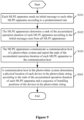
- a process of ranking according to an embodiment may be as shown in Figure 6 , and the present disclosure is not limited thereto.
- each initial message is sent from an apparatus at a tail of an arrow to apparatuses at heads of the arrow.
- a solid box frame indicates that the interim rank of or stored in a corresponding MLPE apparatus is modified after the MLPE apparatus receives the initial message.
- a dashed box frame indicates that the interim rank of or stored in a corresponding MLPE apparatus is unchanged.
- the four MLPE apparatuses send ranking messages successively, the interim ranks stored in each MLPE apparatus is updated, and correct ranks are acquired in step (3), namely, acquired two steps ahead of the case as shown in Figure 2 .
- the photovoltaic string includes more than four MLPE apparatuses.
- a sequence of the MLPE apparatuses is acquired before the MLPE apparatuses communicate with the communication host.
- a network of a photovoltaic system is established only partially based on the communication host, which reduces time consumed in establishing the network.
- Step (4) is further performed after the correct ranks are acquired in process as shown in Figure 6 , so that each MLPE apparatus in the photovoltaic system stores the interim ranks of all MLPE apparatuses. It is prevented that some MLPE apparatuses may not be accessed due to poor network quality when establishing the network.
- the communication host may acquire the sequence of the interim ranks of all MLPE apparatuses in the photovoltaic system when communicating with any MLPE apparatus. It is not necessary to perform another process of sequencing at the communication host, which improves recognition rate and success rate when establishing the network.
- a method for ranking MLPE apparatuses is further provided according to another embodiment of the present.
- a flowchart of the method is as shown in Figure 7 .
- the method further includes step S301.
- step S301 the MLPE apparatuses stop timing the accumulated operation durations synchronously.
- the MLPE apparatuses are installed at different times, that is, the MLPE apparatuses start timing at different moments. After all MLPE apparatuses are installed, the MLPE apparatuses are controlled to stop timing the accumulated operation durations synchronously. Therefore, the accumulated operation durations included in the initial messages sent by each MLPE apparatus are different from each other, and the rank of each MLPE device can be determined according to the aforementioned manner of self-networking.
- the MLPE apparatuses may stop timing the accumulated operation durations synchronously in response to detecting a timing-stop signal.
- the timing-stop signal may be at least one of: a change in an output voltage, a change in an output current, a short-circuit connection, or a preset communication signal.
- the timing-stop signal may be generated by a converter, a switch device, a synchronization device, the communication host, or a power grid, which is in a post-stage of the MLPE apparatuses of the photovoltaic system.
- the synchronization device is taken as an example, and controlling the MLPE apparatuses to stop timing the accumulated operation durations synchronously may include a following process.
- Installation personnel connect the synchronization device to the photovoltaic string, after determining that all the MLPE apparatuses have been installed.
- the additional synchronization device applies a voltage or a current on the photovoltaic string, or transmits a triggering signal to the MLPE apparatuses, so as to trigger the MLPE apparatuses to stop timing the accumulated operation durations synchronously.
- the synchronization device may be add-on equipment, which is only used in installing and debugging the system, and is removed after the system is installed and debugged.
- the power grid may induce a change in voltage, current, frequency, or the like of the photovoltaic string. Further, in a case that the converter is connected to the power grid and starts operating, the power grid may induce a change of voltage, current, frequency, or the like of the photovoltaic string. Therefore, the timing-stop signal may also be generated due to connection with the power grid.
- the timing-stop signal may be generated in one of following manners.
- each MLPE apparatus outputs a preset voltage to a converter after being installed, for example, outputs a safe voltage around 1V.
- An output voltage of a photovoltaic string including 12 MLPE apparatuses connected in series is around 12V
- the converter After receiving an input voltage around 12V, the converter transmits a prompt signal to the communication host, so as to inform the operator that the photovoltaic string has been installed.
- the converter or the switch device is shorted through software control, or the photovoltaic string is manually shorted by the operator, which may reduce the output voltage of the photovoltaic string to zero.
- the MLPE apparatuses stop timing the accumulated operation durations synchronously in response to detecting the short-circuit connection.
- the two photovoltaic strings may be connected in an end-to-end manner, to form a large short-circuit loop. In such case, the accumulated operation durations of all MLPE apparatuses in the two photovoltaic strings may be ranked together.
- Described above are only exemplary manners of triggering the MLPE apparatuses to stop timing the accumulated operation durations synchronously.
- the present disclosure is not limited thereto.
- Other manners of triggering the MLPE apparatuses to stop timing the accumulated operation durations synchronously also fall within the protection scope of the present disclosure.
- the installed MLPE apparatuses of the photovoltaic string may be triggered to stop timing the accumulated operation durations synchronously, so as to prevent random nocturnal power-down from affecting the timing.
- Each installed MLPE apparatus records the accumulated operation duration thereof in such day.
- the timing may be resumed by triggering the installed MLPE apparatuses to start timing again, before installing the remaining photovoltaic modules and MLPE apparatuses.
- the method may further includes followings two steps.
- the MLPE apparatuses determine whether a timing-start signal is detected.
- the MLPE apparatuses resume timing the accumulated operation durations in response to determining that the timing-start signal is detected.
- all the MLPE apparatuses in the photovoltaic string stop timing the accumulated operation durations synchronously, and each MLPE apparatus in the photovoltaic string acquires the accumulated operation durations thereof.
- the MLPE apparatuses After the MLPE apparatuses stop timing the accumulated operation durations synchronously, the MLPE apparatuses send the initial messages according to a predetermined rule, in order to avoid a signal conflict among the MLPE apparatuses when sending the initial messages.
- the predetermined rule may be determined in following manners.
- each MLPE apparatus sends the initial message in response to a random period lapsing after stopping timing the respective accumulated operation duration.
- the MLPE apparatuses may correspond to the random periods different from each other. There may be a small quantity of MLPE apparatuses correspond to identical random periods, which would not result in a severe signal conflict.
- each MLPE apparatus sends the initial message in response to a corresponding preset period lapsing after stopping timing the respective accumulated operation duration.
- the preset period may be acquired based on the accumulated operation duration of the MLPE apparatus. For example, a value of the predetermined period may be in correlation (positive correlation or negative correlation) with the accumulated operation duration of the corresponding MLPE apparatus.
- each MLPE apparatus may sends the initial message in response to a period of T lapsing after the timing being stopped. T may be determined on requirement, for example, equal to the accumulated operation duration divided by 3600.
- Other cases can be obtained by analogy.
- the MLPE apparatuses send the initial message at different moments, since the respective accumulated operation durations of the MLPE apparatuses are different from each other.
- a value of the preset period may be in correlation with a serial number of the corresponding MLPE apparatus.
- the serial number (or part of the serial number) of the MLPE apparatus is converted through calculation into a moment at which the MLPE apparatus sends the initial message.
- the calculated moments for sending the initial messages are different for different MLPE apparatuses, since the serial numbers of the MLPE apparatuses are different from each other.
- each remaining MLPE apparatus determines a respective sending time based on a difference in the respective accumulated operation duration between the one of the MLPE apparatuses and said remaining MLPE apparatus.
- each of the remaining MLPE apparatuses receives and parses the accumulated operation duration included in the received initial message to acquire a difference in the accumulated operation duration between itself and the MLPE apparatus sending the initial message first. Then, a sending time of such remaining MLPE apparatus is determined based on such difference.
- a method for ranking MLPE apparatuses is further provided according to another embodiment of the present disclosure.
- a flowchart of the method is as shown in Figure 8 .
- the method further includes step S401.
- step S401 each MLPE apparatus starts timing the accumulated operation duration in response to detecting a timing-start signal.
- each MLPE apparatus of the photovoltaic string starts timing immediately in response to being powered on, and each MLPE apparatus may acquire the accumulated operation duration thereof as long as the MLPE apparatuses stop timing synchronously.
- various factors may result in inaccuracy in the acquired accumulated operation durations, when the MLPE apparatuses are only controlled to stop timing synchronously.
- the MLPE apparatus may be pre-installed in the photovoltaic module before delivery, or the MLPE apparatus may be integrated in a junction box of the photovoltaic module. In such cases, the MLPE apparatus may be powered in response to being exposed to light, even before the photovoltaic module is transported to the installing position and installed.
- the step S401 is performed before the step S101 in this embodiment. That is, each MLPE starts timing the accumulated operation duration when detecting the corresponding timing-start signal, and then the step S201 is performed, so as to acquire the accumulated operation durations of the MLPE apparatuses.
- the timing-start signal is detectable by each MLPE apparatus during installation.
- the MLPE apparatuses are installed at different moments.
- Each MLPE apparatus may be triggered to start timing the accumulated operation duration in response to detecting the timing-start signal at the moment of installation. Thereby, the MLPE apparatuses start timing at different moments.
- Each MLPE apparatus detects the timing-start signal by at least one of: detecting a predetermined electric change, being subject to a predetermined mechanical change, or receiving a preset signal through communication.
- the predetermined electric change may be being powered.
- the photovoltaic modules are usually installed on site together with the MLPE apparatuses.
- the MLPE apparatus is first fixed on a frame or a support of the photovoltaic module, and an input terminal of the MLPE apparatus is connected to the photovoltaic module. Therefore, the earlier an MLPE apparatus is installed, the earlier such MLPE apparatus is connected to a photovoltaic module, and the earlier such MLPE apparatus is powered and starts timing the accumulated operation duration.
- Different MLPE apparatuses are installed at different moments, and thereby record different accumulated operation durations.
- a case of a reconstructed photovoltaic system is similar to the one of the new photovoltaic system.
- Photovoltaic modules have been installed in the reconstructed system.
- the earlier such MLPE apparatus is connected to a photovoltaic module, the earlier such MLPE apparatus is powered and starts timing the accumulated operation duration.
- Different MLPE apparatuses are installed at different moments, and thereby record different accumulated operation durations.
- the predetermined electric change may be a change of an electric parameter at an input terminal or an output terminal.
- the electric parameter includes a voltage, a current, a frequency, or the like.
- a MLPE apparatus detects that an input voltage is greater than 20V, it is indicated that the MLPE apparatus has been installed on a photovoltaic module, and thereby the MLPE apparatus may start timing.
- a MLPE apparatus detects that an output voltage is equal to 1V, it is indicated that the MLPE apparatus has been powered and in an initial state, and thereby the MLPE apparatus may start timing.
- an additional device may be configured to detect the change of the electric parameter at the input terminal or an output terminal of an MLPE apparatus may be detected, in order to trigger the MLPE apparatus to start timing.
- an output terminal of the MLPE apparatus is provided with a voltage generator, and the voltage generator is configured to generate a voltage following a predetermined rule, so that the MLPE apparatus is capable to detect the voltage accurately.
- the MLPE apparatus may be powered in response to being exposed to light, even before the photovoltaic module is transported to the installing position and installed.
- the timing-start signal may be detected in response to the MLPE apparatus being subject to a predetermined mechanical change.
- the predetermined mechanical change may be: a predetermined component being installed or removed, a predetermined component being connected or disconnected, or a state of a predetermined component being changed.
- Examples of removing the predetermined component from the MLPE apparatus may be as follows.
- a plug configured to connect and disconnect two nodes in the MLPE apparatus is pre-installed in the MLPE apparatus before delivery.
- the plug is temporarily or permanently removed to establish or break connection between the two nodes.
- the MLPE apparatus is triggered to start timing in response to detecting the connection between the two nodes being established or broken.
- the predetermined component may operate based on electromagnetic induction, for example, may be a magnetic strip or a component provided with a near field communication (NFC) chip.
- NFC near field communication
- the MLPE apparatus In response to the component being removed temporarily or permanently, the MLPE apparatus detects an internal change of a magnetic field or a communication signal, and the timing is triggered to start.
- Examples of installing the predetermined component to the MLPE apparatus may be as follows. For example, a socket is reserved in the MLPE apparatus before delivery. During installing the MLPE apparatus or the photovoltaic module in which the MLPE apparatus is pre-installed or integrated, the timing is triggered to start in response to the component being inserted into the socket.
- the component may be provided in a package of the MLPE apparatus, or may be a conventional tool for on-site installation, such as a screwdriver.
- the component may be permanently removed or installed, in order to trigger the MLPE apparatus to start timing. Alternatively, the component may be temporarily removed or inserted once. For example, the screwdriver is inserted to the socket once and then pulled out immediately, to trigger the MLPE apparatus to start timing.
- the predetermined component may operate based on electromagnetic induction, for example, may be a magnetic strip or a component provided with a NFC chip.
- the MLPE apparatus detects an internal change of a magnetic field or a communication signal, and the timing is triggered to start.
- An example of connecting the predetermined component of the MLPE apparatus may be as follows. Two output terminals of the MLPE apparatus or the photovoltaic module in which the MLPE apparatus is pre-installed or integrated are in a floating state when delivery. During installation, the two output terminals are transiently coupled with each other, which is detected by the MLPE apparatus, and thereby timing is triggered to start.
- An example of disconnecting the predetermined component of the MLPE apparatus may be as follows. Two output terminals of the MLPE apparatus or the photovoltaic module in which the MLPE apparatus is pre-installed or integrated are shorted when delivery. During installation, the two output terminals disconnected from each other, which is detected by the MLPE apparatus, and thereby timing is triggered to start.
- An example of a state of the predetermined component of the MLPE apparatus being changed may be as follows.
- a button, a knob, or a dial switch is reserved on an MLPE apparatus.
- a state of the button, the knob, or the dial switch is changed to trigger the MLPE apparatus to start timing.
- each MLPE apparatus may detect the timing-start signal in response to receiving a preset signal indicating starting the timing, which is transmitted through communication.
- the preset signal may be transmitted from an external device. That is, each MLPE apparatus is triggered to start timing by an external communication signal.
- the communication signal is generated by a portable device, such as a mobile phone or a smart wearable device with a communication function (for example, a smart bracelet, smart glasses, or a smart ring).
- the communication signal is transmitted to the MLPE apparatus to trigger the timing, by using a protocol suitable for communication over a short distance, such as the NFC or the Bluetooth, in response to the mobile phone or the smart wearable device with a communication function approaching the MLPE apparatus.
- the protocol suitable for communication over the short distance is advantageous in that triggering timing of one MLPE apparatus would not lead to erroneously triggering timing of another located nearby.
- the aforementioned communication signal may further be configured as a signal for activating the MLPE apparatus.
- the MLPE apparatus may output a safe voltage before being activated, and may output normal power after being activated.
- step S501 is performed after the MLPE apparatuses communicate with the communication host and report the accumulated operation duration ranks of the MLPE apparatuses to the communication host.
- a flowchart of the method is as shown in Figure 9 .
- a communication host in the photovoltaic system determines a physical location of each device in the photovoltaic string according to the rank of the accumulated operation duration of each MLPE apparatus and a sequence of installing positions of the devices in the photovoltaic string. The devices are installed at the installing positions based on the sequence.
- the devices in the photovoltaic string include photovoltaic modules, or the MLPE apparatuses in a post-stage of photovoltaic modules.
- the photovoltaic system may include a photovoltaic string, and the photovoltaic string may include twelve photovoltaic modules sequentially installed at installation positions #1, #2.
- the twelve photovoltaic modules correspond to twelve MLPE apparatuses, 1 to 12, respectively.
- the photovoltaic modules are installed successively following a direction of an arrow line as shown in Figure 4 , that is, the photovoltaic modules and the corresponding MLPE apparatuses are installed at the installation position #1 first, and installed at the installation position #12 last.
- the MLPE apparatuses can be mapped to the installation positions according to the ranks of the accumulation operation durations and the sequence of the installation positions, and accordingly the physical location of each MLPE apparatus or each photovoltaic module can be determined.
- the sequence of the installation positions as shown in Figure 4 is only exemplary, and the present disclosure is not limited thereto. Those skilled in the art may design another sequence of the installation positions according to actual conditions, which also falls within the protection scope of the present disclosure.
- An MLPE apparatus is further provided according to another embodiment of the present disclosure.
- a schematic structural diagram of the MLPE apparatus may be as shown in Figure 10 .
- the MLPE apparatus includes a main circuit 110, a detector 120, and a controller 130.
- the detector 120 is configured to detect a signal, such as the timing-stop signal.
- An input of the main circuit 110 receives power from a photovoltaic module in a photovoltaic system.
- An output of the main circuit 110 is connected to an output of a main circuit 110 of another MLPE apparatus in parallel or in series, to form a photovoltaic string in the photovoltaic system.
- the controller 130 is coupled to the main circuit 110 and the detector 120, and is in communication connection with each other MLPE apparatus in the photovoltaic string.
- the controller 130 is configured to perform any aforementioned method for ranking the MLPE apparatuses.
- the controller 130 includes the built-in predetermined rule for sending the initial message of the MLPE apparatus.
- Each initial message includes the serial number and the accumulated operation duration, and may include the interim rank of the accumulated operation duration when required.
- the controller 130 is configured to control an operation state of the main circuit 110, determine the rank of the accumulated operation duration of the MLPE apparatus according to the initial messages sent from all MLPE apparatuses, and report the rank of the accumulated operation duration of the MLPE apparatus to the communication host after the MLPE apparatus communicates with the communication host. Accordingly, the communication host may determine the physical location of each device in the photovoltaic string, according to the rank of the accumulated operation duration of each MLPE apparatus and the sequence of the installing positions of the devices in the photovoltaic string.
- the MLPE apparatus may be: a power optimizer configured to perform maximum power point tracking (MPPT) on a photovoltaic module, a rapid shutdown device configured to switch on and off a photovoltaic module, or a module monitor.
- MPPT maximum power point tracking
- outputs of the main circuit 110 of all MLPE apparatuses in a same photovoltaic string are connected in series.
- the power optimizer includes a direct-current (DC) power optimizer or an alternating-current (AC) power optimizer.
- the DC power optimizer converts a low-voltage DC input into a low-voltage DC output, and the low-voltage DC outputs are connected in series to acquire a high-voltage DC output.
- the AC power optimizer converts a low-voltage DC input into a low-voltage AC output, and the low-voltage AC outputs are connected in series to acquire a high-voltage AC output.
- the MLPE apparatus may alternatively be a micro inverter. In such case, outputs of the main circuits 110 of all MLPE apparatuses in a same photovoltaic string are connected in parallel.
- the present disclosure is not limited to the above examples.
- Reference is made to Figure 11 and Figure 12 which show schematic structures of a Buck optimizer and a rapid shutdown device, respectively.
- a photovoltaic system is further provided according to another embodiment of the present disclosure.
- a schematic structural diagram of the system may be as shown in Figure 13 .
- the system includes a communication host 210 and at least one photovoltaic string 220.
- the photovoltaic string 220 includes multiple photovoltaic modules that are connected in parallel (as shown in Figure 13 ) or in series (as shown in Figure 14 ) via corresponding MLPE apparatuses.
- the communication host 210 receives the rank of the accumulated operation duration reported by each MLPE apparatus, and determines the physical location of each photovoltaic module or each MLPE apparatus according to the rank of the accumulated operation duration of each MLPE apparatus and a sequence of installing positions of the devices in the photovoltaic string 220. The devices are installed at the installing positions based on the sequence.
- the communication host 210 is communication connection with the MLPE apparatuses, and is configured perform any aforementioned method for locating the devices in the photovoltaic string.
- outputs of the MLPE apparatus may be directly connected into a power grid, and there may be no converter in a post-stage of the MLPE apparatus (as shown in Figure 13 ).
- the Buck optimizer or the rapid shutdown device it is necessary to arrange a converter in a post-stage of the MLPE apparatus, so as to convert DC power of the photovoltaic string into AC power and transmit the AC power to a grid (as shown in Figure 14 ).
- the converter may be a DC-DC converter or a DC-AC converter, for example, a photovoltaic inverter or an energy-storage current transformer.
- the present disclosure is not limited to the above examples.
- low-voltage AC outputs of the MLPE apparatus are connected in series to form a high-voltage AC output, which may be directly connected into a power grid.
- the converter in the post-stage of the MLPE apparatus as shown in Figure 14 may not be necessary
- ranking of the MLPE apparatuses may be performed among all photovoltaic strings 220, and alternatively may be performed in each photovoltaic string 220 separately. In the latter case, a result of the ranking of each photovoltaic string 220 is mapped to the corresponding photovoltaic string 220 at the communication host 210.
- the communication host 210 may be a controller in the photovoltaic system, such as a system controller or an internal controller of a converter.
- the communication host 210 may be a near-end controller in communication connection with a controller in the photovoltaic system, such as a local personal computer (PC).
- the communication host 210 may be a remote server, a cloud server, or a display terminal (such as a mobile phone), which in communication connection with any aforementioned controller.
- the present disclosure is not limited to the above examples.
- the communication host 210 may communicate with a post-stage converter or each MLPE apparatus through wired communication (for example, under RS485 standards or the Ethernet technology), wireless communication (for example, under WIFI, Bluetooth, ZigBee, or LoRa), or a power line carrier communication, all of which fall within the protection scope of the present disclosure.
- wired communication for example, under RS485 standards or the Ethernet technology
- wireless communication for example, under WIFI, Bluetooth, ZigBee, or LoRa
- a power line carrier communication all of which fall within the protection scope of the present disclosure.
- the photovoltaic string is a part of a photovoltaic array, and further a part of a photovoltaic system.
- the aforementioned device in the photovoltaic string may be regarded as a device in the photovoltaic array or a device in the photovoltaic system.
- the method for locating the devices in the photovoltaic string may be regarded as a method for locating devices in the photovoltaic array, or a method for locating devices in the photovoltaic system.
Landscapes
- Engineering & Computer Science (AREA)
- Business, Economics & Management (AREA)
- Health & Medical Sciences (AREA)
- Power Engineering (AREA)
- Computer Networks & Wireless Communication (AREA)
- Signal Processing (AREA)
- General Health & Medical Sciences (AREA)
- Economics (AREA)
- Strategic Management (AREA)
- Medical Informatics (AREA)
- Water Supply & Treatment (AREA)
- Tourism & Hospitality (AREA)
- Physics & Mathematics (AREA)
- General Business, Economics & Management (AREA)
- General Physics & Mathematics (AREA)
- Theoretical Computer Science (AREA)
- Computing Systems (AREA)
- Primary Health Care (AREA)
- Public Health (AREA)
- Marketing (AREA)
- Human Resources & Organizations (AREA)
- Remote Monitoring And Control Of Power-Distribution Networks (AREA)
- Photovoltaic Devices (AREA)
- Management, Administration, Business Operations System, And Electronic Commerce (AREA)
- Data Exchanges In Wide-Area Networks (AREA)
- Selective Calling Equipment (AREA)
- Information Transfer Between Computers (AREA)
Claims (15)
- Procédé de classement d'appareils MLPE, sachant que les appareils MLPE sont en connexion de communication les uns avec les autres dans un système photovoltaïque, et le procédé comprend :le démarrage, par chaque appareil MLPE, d'un chronométrage d'une durée de fonctionnement accumulée dudit appareil MLPE en réponse à la détection d'un signal de démarrage de chronométrage, sachant que le signal de démarrage de chronométrage est décelable par chaque appareil MLPE pendant l'installation dudit appareil MLPE ;l'envoi (S101), par chaque appareil MLPE selon une règle prédéterminée, d'un message initial à chaque autre appareil MLPE, sachant que le message initial comprend un numéro de série correspondant audit appareil MLPE et la durée de fonctionnement accumulée dudit appareil MLPE ;la détermination (S102), par les appareils MLPE, d'un rang de la durée de fonctionnement accumulée de chaque appareil MLPE parmi les durées de fonctionnement accumulées des appareils MLPE selon les messages initiaux envoyés depuis tous les appareils MLPE ;la communication (S103), par les appareils MLPE, avec un hôte de communication du système photovoltaïque ; etle signalement (S103), par les appareils MLPE, du rang de la durée de fonctionnement accumulée de chaque appareil MLPE à l'hôte de communication.
- Le procédé selon la revendication 1, sachant que :le message initial comprend en outre un rang provisoire de la durée de fonctionnement accumulée ; etla détermination, par les appareils MLPE, du rang de la durée de fonctionnement accumulée de chaque appareil MLPE selon les messages initiaux envoyés depuis tous les appareils MLPE comprend :en réponse à la réception, par chaque appareil MLPE, d'un message de classement,la comparaison, par ledit appareil MLPE, de la durée de fonctionnement accumulée comprise dans le message de classement avec la durée de fonctionnement accumulée dudit appareil MLPE pour obtenir un premier résultat de comparaison ; etle fait de déterminer, par ledit appareil MLPE sur la base du premier résultat de comparaison, s'il convient d'ajuster le rang provisoire de la durée de fonctionnement accumulée dudit appareil MLPE ;sachant que le message de classement est le message initial envoyé depuis n'importe quel autre appareil MLPE.
- Le procédé selon la revendication 2, sachant que :le rang provisoire compris dans le message de classement est identique au rang provisoire de la durée de fonctionnement accumulée dudit appareil MLPE ;le fait de déterminer, par ledit appareil MLPE, s'il convient d'ajuster le rang provisoire de la durée de fonctionnement accumulée dudit appareil MLPE sur la base du résultat de la comparaison comprend :l'augmentation du rang provisoire de l'appareil MLPE de 1, en réponse au fait que la durée de fonctionnement accumulée dudit appareil MLPE est plus courte que la durée de fonctionnement accumulée comprise dans le message de classement ; etle fait de maintenir le rang provisoire de l'appareil MLPE inchangé, en réponse au fait que la durée de fonctionnement accumulée dudit appareil MLPE est plus longue que la durée de fonctionnement accumulée comprise dans le message de classement ; etla détermination, par les appareils MLPE, du rang de la durée de fonctionnement accumulée de chaque appareil MLPE selon les messages initiaux envoyés depuis tous les appareils MLPE comprend en outre :le fait de déterminer, par chaque appareil MLPE, si le rang provisoire compris dans chaque message initial reçu au sein d'une période prédéfinie est différent du rang provisoire dudit appareil MLPE ; etle fait de déterminer, par chaque appareil MLPE, le rang provisoire dudit appareil MLPE en tant que le rang de la durée de fonctionnement accumulée dudit appareil MLPE, en réponse au fait de déterminer que le rang provisoire compris dans chaque message initial reçu au sein de la période prédéfinie est différent du rang provisoire dudit appareil MLPE.
- Le procédé selon l'une quelconque des revendications 1 à 3, comprenant en outre, pour chaque appareil MLPE en réponse à la réception d'un message de classement :le stockage du rang provisoire et de la durée de fonctionnement accumulée compris dans le message de classement ;en réponse au fait que le rang provisoire compris dans le message de classement est identique au rang provisoire de la durée de fonctionnement accumulée dudit appareil MLPE,la comparaison de la durée de fonctionnement accumulée comprise dans le message de classement avec la durée de fonctionnement accumulée dudit appareil MLPE pour obtenir un premier résultat de comparaison, etl'augmentation, de 1, du rang provisoire d'un appareil MLPE correspondant à la durée de fonctionnement accumulée plus courte dans le premier résultat de comparaison ; eten réponse au fait que le rang provisoire compris dans le message de classement est identique à n'importe quel rang provisoire stocké dans ledit appareil MLPE,la comparaison de la durée de fonctionnement accumulée comprise dans le message de classement avec la durée de fonctionnement accumulée correspondant audit rang provisoire stocké dans ledit appareil MLPE, pour obtenir un deuxième résultat de comparaison, etl'augmentation, de 1, du rang provisoire d'un appareil MLPE correspondant à la durée de fonctionnement accumulée plus courte dans le deuxième résultat de comparaison ;sachant que le message de classement est le message initial envoyé depuis n'importe quel autre appareil MLPE ;sachant que la détermination, par les appareils MLPE, du rang de la durée de fonctionnement accumulée de chaque appareil MLPE selon les messages initiaux envoyés depuis tous les appareils MLPE comprend en outre :le fait de déterminer, par chaque appareil MLPE, si le rang provisoire compris dans chaque message initial reçu au sein d'une période prédéfinie est identique au rang provisoire stocké d'un appareil MLPE envoyant ledit message initial ; etla détermination, par les appareils MLPE, du rang provisoire de chaque appareil MLPE en tant que le rang de la durée de fonctionnement accumulée dudit appareil MLPE, en réponse au fait de déterminer, par chaque appareil MLPE, que le rang provisoire compris dans chaque message de classement reçu au sein d'une période prédéfinie est identique au rang provisoire stocké d'un appareil MLPE envoyant ledit message de classement.
- Le procédé selon l'une quelconque des revendications 1 à 4, sachant qu'avant l'envoi, par chaque appareil MLPE selon la règle prédéterminée, du message initial à chaque autre appareil MLPE, le procédé comprend en outre :
l'arrêt (S301), par les appareils MLPE de manière synchrone, du chronométrage des durées de fonctionnement accumulées. - Le procédé selon la revendication 5, sachant que l'arrêt, par les appareils MLPE de manière synchrone, du chronométrage des durées de fonctionnement accumulées comprend :
l'arrêt, par les appareils MLPE de manière synchrone, du chronométrage des durées de fonctionnement accumulées en réponse à la détection d'un signal d'arrêt de chronométrage. - Le procédé selon la revendication 6, sachant qu'après l'arrêt, par les appareils MLPE, du chronométrage des durées de fonctionnement accumulées de manière synchrone, le procédé comprend :le fait de déterminer, par les appareils MLPE, si un autre signal de démarrage de chronométrage est détecté ;la reprise, par les appareils MLPE, du chronométrage des durées de fonctionnement accumulées en réponse au fait de déterminer que le signal de démarrage de chronométrage est détecté ; etl'arrêt, par les appareils MLPE de manière synchrone, du chronométrage des durées de fonctionnement accumulées en réponse au fait de déterminer que le signal d'arrêt de chronométrage est détecté de nouveau.
- Le procédé selon l'une quelconque des revendications 1 à 7, sachant que l'envoi, par chaque appareil MLPE selon la règle prédéterminée, du message initial à chaque autre appareil MLPE comprend :l'envoi, par chaque appareil MLPE, du message initial en réponse au fait qu'une période aléatoire expire après l'arrêt du chronométrage de la durée de fonctionnement accumulée respective ; oul'envoi, par chaque appareil MLPE, du message initial en réponse au fait qu'une période prédéfinie correspondante expire après l'arrêt du chronométrage de la durée de fonctionnement accumulée respective,sachant que la période prédéfinie correspondante est déterminée par la durée de fonctionnement accumulée respective de chaque appareil MLPE, ou un numéro de série correspondant audit appareil MLPE.
- Le procédé selon l'une quelconque des revendications 1 à 8, sachant que l'envoi, par chaque appareil MLPE selon la règle prédéterminée, du message initial à chaque autre appareil MLPE comprend :
en réponse à la réception de la durée de fonctionnement accumulée respective depuis n'importe quel autre des appareils MLPE,la détermination d'un moment d'envoi sur la base d'une différence entre la durée de fonctionnement accumulée reçue et la durée de fonctionnement accumulée desdits appareils MLPE, etl'envoi du message initial au moment d'envoi. - Procédé de localisation de dispositifs dans une chaîne photovoltaïque, sachant que la chaîne photovoltaïque comprend des appareils MLPE qui sont en connexion de communication les uns avec les autres dans un système photovoltaïque, et le procédé comprend :le procédé selon l'une quelconque des revendications 1 à 9 ; etla détermination (S501), par un hôte de communication dans le système photovoltaïque, d'un emplacement physique de chacun des dispositifs dans la chaîne photovoltaïque, selon le rang de la durée de fonctionnement accumulée de chaque appareil MLPE et une séquence de positions d'installation des dispositifs dans la chaîne photovoltaïque ;sachant que les dispositifs sont installés dans les positions d'installation sur la base de la séquence.
- Le procédé selon la revendication 10, sachant que la détermination, par l'hôte de communication, de l'emplacement physique de chacun des dispositifs dans la chaîne photovoltaïque comprend :l'acquisition, par l'hôte de communication, d'une séquence des appareils MLPE selon le rang de la durée de fonctionnement accumulée de chaque appareil MLPE ; etla mise en correspondance, par l'hôte de communication, de la séquence des appareils MLPE avec la séquence de positions d'installation des dispositifs dans la chaîne photovoltaïque, pour déterminer l'emplacement physique de chacun des dispositifs.
- Le procédé selon la revendication 10 ou 11, sachant que les dispositifs dans la chaîne photovoltaïque sont des modules photovoltaïques, ou les appareils MLPE dans un étage postérieur de modules photovoltaïques.
- Appareil MLPE, comprenant :un circuit principal, sachant qu'une entrée du circuit principal reçoit de la puissance depuis un module photovoltaïque dans un système photovoltaïque, et une sortie du circuit principal est connectée en parallèle ou en série à une sortie d'un circuit principal d'un autre appareil MLPE, pour former une chaîne photovoltaïque dans le système photovoltaïque ;un détecteur, configuré pour détecter un signal ; etun dispositif de commande, couplé au circuit principal et au détecteur, sachant que le dispositif de commande est en connexion de communication avec chaque autre appareil MLPE dans la chaîne photovoltaïque, et est configuré pour effectuer le procédé selon l'une quelconque des revendications 1 à 9.
- Système photovoltaïque, comprenant :un hôte de communication, etau moins une chaîne photovoltaïque,sachant que la chaîne photovoltaïque comprend une pluralité de modules photovoltaïques qui sont connectés en parallèle ou en série via des appareils MLPE correspondants ; etsachant que l'hôte de communication est en connexion de communication avec les appareils MLPE ; etsachant que l'hôte de communication et les appareils MLPE sont configurés pour effectuer le procédé selon l'une quelconque des revendications 10 à 12.
- Le système photovoltaïque selon la revendication 14, sachant que :des sorties de circuits principaux des appareils MLPE dans une de l'au moins une chaîne photovoltaïque sont connectées en série, et les appareils MLPE sont des optimiseurs de puissance, des dispositifs d'arrêt rapide, ou des dispositifs de surveillance de module ; oudes sorties des circuits principaux des appareils MLPE dans une de l'au moins une chaîne photovoltaïque sont connectées en parallèle, et les appareils MLPE sont des micro-onduleurs.
Applications Claiming Priority (1)
| Application Number | Priority Date | Filing Date | Title |
|---|---|---|---|
| CN202010869819.7A CN112017072B (zh) | 2020-08-26 | 2020-08-26 | 光伏系统、组串内设备的定位方法和mlpe设备及其排序方法 |
Publications (3)
| Publication Number | Publication Date |
|---|---|
| EP3961916A1 EP3961916A1 (fr) | 2022-03-02 |
| EP3961916B1 true EP3961916B1 (fr) | 2023-11-01 |
| EP3961916C0 EP3961916C0 (fr) | 2023-11-01 |
Family
ID=73502235
Family Applications (1)
| Application Number | Title | Priority Date | Filing Date |
|---|---|---|---|
| EP21191001.3A Active EP3961916B1 (fr) | 2020-08-26 | 2021-08-12 | Système photovoltaïque, procédé permettant de localiser des dispositifs dans une chaîne photovoltaïque, appareil mlpe et procédé pour classer des appareils mlpe |
Country Status (5)
| Country | Link |
|---|---|
| US (1) | US11894687B2 (fr) |
| EP (1) | EP3961916B1 (fr) |
| JP (1) | JP7337126B2 (fr) |
| CN (1) | CN112017072B (fr) |
| AU (1) | AU2021218086B2 (fr) |
Families Citing this family (3)
| Publication number | Priority date | Publication date | Assignee | Title |
|---|---|---|---|---|
| CN113489057A (zh) * | 2021-07-06 | 2021-10-08 | 阳光新能源开发有限公司 | 一种光伏系统、光伏组串接线方法及装置 |
| CN115603661A (zh) * | 2022-10-19 | 2023-01-13 | 杭州禾迈电力电子股份有限公司(Cn) | 光伏设备搜索方法、管理模块、系统及存储介质 |
| CN115378052B (zh) * | 2022-10-19 | 2023-03-24 | 杭州禾迈电力电子股份有限公司 | 光伏设备分组方法、管理模块、光伏设备、系统及介质 |
Citations (1)
| Publication number | Priority date | Publication date | Assignee | Title |
|---|---|---|---|---|
| US20130346054A1 (en) * | 2012-06-26 | 2013-12-26 | Asim Mumtaz | System, method and apparatus for generating layout of devices in solar installations |
Family Cites Families (44)
| Publication number | Priority date | Publication date | Assignee | Title |
|---|---|---|---|---|
| US4143321A (en) * | 1977-05-25 | 1979-03-06 | The Boeing Co. | Apparatus and process for grouping pulse signals according to source |
| JPS62213426A (ja) | 1986-03-14 | 1987-09-19 | Hitachi Ltd | 電灯線搬送ホ−ムコントロ−ルシステム |
| JPH0546360A (ja) | 1991-08-16 | 1993-02-26 | Mitsubishi Electric Corp | ソーテイング装置 |
| JPH07336897A (ja) | 1994-06-03 | 1995-12-22 | Nissin Electric Co Ltd | 分散電源用インバータ装置及びその制御方法 |
| JP3245504B2 (ja) | 1994-09-27 | 2002-01-15 | シャープ株式会社 | インバータ装置 |
| JPH09182279A (ja) | 1995-10-26 | 1997-07-11 | Nitto Kogyo Kk | 太陽光発電システムにおける短絡検出装置 |
| CA2223314C (fr) * | 1996-12-03 | 2003-03-18 | Kabushiki Kaisha Toshiba | Systeme de protection et de controle du circuit d'alimentation electrique, et systeme de commande asservi |
| JP2004015868A (ja) | 2002-06-04 | 2004-01-15 | Toshiba Corp | 電気所の保護制御システム及び差動保護継電器 |
| JP5057766B2 (ja) | 2006-12-15 | 2012-10-24 | シャープ株式会社 | 太陽光発電システムおよび保存装置 |
| US8310366B2 (en) * | 2008-12-18 | 2012-11-13 | Symbol Technologies, Inc. | RFID device and related method for providing assistance for locating it |
| JP5492432B2 (ja) | 2009-03-18 | 2014-05-14 | 中国電力株式会社 | 監視装置、監視システムおよびプログラム |
| JP2013526824A (ja) * | 2010-05-07 | 2013-06-24 | アドバンスド エナージィ インダストリーズ,インコーポレイテッド | 太陽光発電予測システム並びに方法 |
| US20110282600A1 (en) * | 2010-05-12 | 2011-11-17 | General Electric Company | System and method for photovoltaic plant power curve measurement and health monitoring |
| KR101239015B1 (ko) * | 2010-05-25 | 2013-03-04 | 주식회사 텔에이스 | 전파측위용 지상 고정형 송신기의 시각 동기 방법 및 간섭 제거 방법 |
| JP2012204571A (ja) | 2011-03-25 | 2012-10-22 | Toshiba Corp | 発電システム監視装置およびコンピュータプログラム |
| KR101254957B1 (ko) * | 2011-07-18 | 2013-04-16 | 이흥수 | 교통 신호 제어 장치 및 방법 |
| WO2013051157A1 (fr) | 2011-10-07 | 2013-04-11 | 日立ビークルエナジー株式会社 | Système de surveillance de batteries, organe de commande hôte et dispositif de surveillance de batteries |
| CN103248399A (zh) | 2012-02-08 | 2013-08-14 | 台达电子工业股份有限公司 | 电力线通讯方法及电力线通讯系统 |
| JP2014099571A (ja) | 2012-11-16 | 2014-05-29 | Chube Univ | 太陽光発電ユニット |
| US9590559B2 (en) * | 2012-11-23 | 2017-03-07 | Solar Analytics Pty Ltd. | Monitoring system |
| JP5636621B2 (ja) | 2013-01-29 | 2014-12-10 | ソーラー・エナジー・ソリューションズ株式会社 | 太陽光発電監視方法 |
| CA2953834C (fr) * | 2014-08-04 | 2020-07-14 | Sungrow Power Supply Co., Ltd. | Systeme et procede de protection pour onduleur photovoltaique connecte au reseau |
| US10505370B2 (en) * | 2014-09-30 | 2019-12-10 | Sungrow Power Supply Co., Ltd. | Safety detection device and method of grid-connected inverter |
| CN104704702B (zh) * | 2015-01-29 | 2017-01-11 | 湖北民族学院 | 光伏发电系统及其故障检测方法 |
| US10003300B2 (en) * | 2015-10-09 | 2018-06-19 | Sunpower Corporation | Photovoltaic management and module-level power electronics |
| US10126131B2 (en) * | 2015-10-26 | 2018-11-13 | Enphase Energy, Inc. | Automated photovoltaic geospatial location |
| US10365309B2 (en) * | 2015-12-17 | 2019-07-30 | Enphase Energy, Inc. | Method and apparatus for using module-level power electronics data for validating distributed energy resource system parameters |
| CN105790302B9 (zh) * | 2016-04-11 | 2018-08-07 | 阳光电源股份有限公司 | 一种级联型光伏并网逆变器及其控制方法和控制装置 |
| US20170363666A1 (en) * | 2016-06-16 | 2017-12-21 | Enphase Energy, Inc. | Method and apparatus for energy flow visualization |
| US10985694B2 (en) * | 2016-07-15 | 2021-04-20 | Enphase Energy, Inc. | Method and apparatus for determining key performance photovoltaic characteristics using sensors from module-level power electronics |
| US20180026575A1 (en) * | 2016-07-25 | 2018-01-25 | Sunpower Corporation | Solar roof mounting surface transition |
| CN106253334B (zh) * | 2016-08-19 | 2018-12-28 | 阳光电源股份有限公司 | 一种级联型光伏并网逆变器及其控制方法和控制装置 |
| CN106230003B (zh) * | 2016-08-22 | 2019-08-13 | 阳光电源股份有限公司 | 一种级联多电平逆变系统及其调制方法和控制器 |
| CN106646641A (zh) * | 2016-12-29 | 2017-05-10 | 上海瑞示电子科技有限公司 | 一种基于多个探测器的检测方法及系统 |
| CN106992550B (zh) * | 2017-05-26 | 2021-04-13 | 阳光电源股份有限公司 | 一种控制装置及汇流箱 |
| US20190036481A1 (en) * | 2017-07-25 | 2019-01-31 | Sunpower Corporation | Photovoltaic module with distributed power conversion circuits |
| KR101983453B1 (ko) | 2017-08-04 | 2019-05-28 | 성창 주식회사 | 군집 태양광 트래커들의 제어 방법 및 시스템 |
| CN108183682B (zh) * | 2018-01-15 | 2021-04-09 | 重庆华智天下科技有限公司 | 一种居民屋顶光伏板端电压自动对线装置 |
| EP3667902A1 (fr) | 2018-12-12 | 2020-06-17 | Solaredge Technologies Ltd. | Appareil et procédé permettant de déterminer un ordre de dispositifs de puissance dans des systèmes de production de puissance |
| CN109861644B (zh) * | 2018-12-24 | 2020-07-07 | 阳光电源股份有限公司 | 光伏组件故障诊断方法、边缘计算处理装置和逆变器 |
| CN110198358A (zh) * | 2019-07-05 | 2019-09-03 | 深圳艾为电气技术有限公司 | 一种基于LoRa物联网的烘干设备控制系统 |
| CN111131536B (zh) * | 2019-12-09 | 2021-07-13 | 珠海格力电器股份有限公司 | 通讯地址的高效配置方法及装置、系统、电表 |
| CN111050287A (zh) * | 2019-12-20 | 2020-04-21 | 福州数据技术研究院有限公司 | 一种低功耗射频识别定位系统及其方法 |
| CN111262767B (zh) * | 2020-03-27 | 2022-11-15 | 阳光电源股份有限公司 | 一种光伏系统及其通信方法 |
-
2020
- 2020-08-26 CN CN202010869819.7A patent/CN112017072B/zh active Active
-
2021
- 2021-08-12 EP EP21191001.3A patent/EP3961916B1/fr active Active
- 2021-08-17 US US17/404,181 patent/US11894687B2/en active Active
- 2021-08-18 AU AU2021218086A patent/AU2021218086B2/en active Active
- 2021-08-23 JP JP2021135731A patent/JP7337126B2/ja active Active
Patent Citations (1)
| Publication number | Priority date | Publication date | Assignee | Title |
|---|---|---|---|---|
| US20130346054A1 (en) * | 2012-06-26 | 2013-12-26 | Asim Mumtaz | System, method and apparatus for generating layout of devices in solar installations |
Also Published As
| Publication number | Publication date |
|---|---|
| EP3961916A1 (fr) | 2022-03-02 |
| US20220069586A1 (en) | 2022-03-03 |
| AU2021218086B2 (en) | 2023-06-08 |
| US11894687B2 (en) | 2024-02-06 |
| JP7337126B2 (ja) | 2023-09-01 |
| AU2021218086A1 (en) | 2022-03-17 |
| CN112017072B (zh) | 2024-05-14 |
| EP3961916C0 (fr) | 2023-11-01 |
| CN112017072A (zh) | 2020-12-01 |
| JP2022040047A (ja) | 2022-03-10 |
Similar Documents
| Publication | Publication Date | Title |
|---|---|---|
| EP3961916B1 (fr) | Système photovoltaïque, procédé permettant de localiser des dispositifs dans une chaîne photovoltaïque, appareil mlpe et procédé pour classer des appareils mlpe | |
| US11728443B2 (en) | Systems and methods for remote or local shut-off of a photovoltaic system | |
| EP2798720B1 (fr) | Dispositif de chargement, procédé de commande de dispositif de chargement, et procédé de détection de dispositif périphérique | |
| CN106849263B (zh) | 一种供电设备、供电系统、供电方法 | |
| JP6424699B2 (ja) | 通信システム | |
| US11626837B2 (en) | Photovoltaic system and method for locating devices in photovoltaic string | |
| CN110147154A (zh) | 实现掉电上电的方法、装置和电路 | |
| EP3226179A1 (fr) | Appareil électronique | |
| JP2008009658A (ja) | 通信端末装置および同装置を内蔵した電力量計 | |
| CN217563394U (zh) | 本质安全型远控装置 | |
| CN215180698U (zh) | 一种智能电网开关检测电路、装置及其系统 | |
| CN210578228U (zh) | 一种设有检测装置的直流电源装置 | |
| CN221102615U (zh) | 智能插头、供电控制系统和电子设备 | |
| CN214799042U (zh) | 工业交流电监测管理系统 | |
| CN215185946U (zh) | 电源机柜 | |
| CN212627318U (zh) | 一种远程控制的线路智能负荷开关 | |
| EP3136610B1 (fr) | Appareil electronique et procede | |
| JP2000253585A (ja) | 分散電源システム | |
| CN118054469A (zh) | 一种电力系统的稳定性控制系统及方法 | |
| CN112018899A (zh) | 一种远程控制的线路智能负荷开关 | |
| CN116317160A (zh) | 一种电源远程控制装置及电能终端设备 | |
| JP2017055617A (ja) | 蓄電池、電力管理システム、及び電力管理方法 |
Legal Events
| Date | Code | Title | Description |
|---|---|---|---|
| PUAI | Public reference made under article 153(3) epc to a published international application that has entered the european phase |
Free format text: ORIGINAL CODE: 0009012 |
|
| STAA | Information on the status of an ep patent application or granted ep patent |
Free format text: STATUS: THE APPLICATION HAS BEEN PUBLISHED |
|
| AK | Designated contracting states |
Kind code of ref document: A1 Designated state(s): AL AT BE BG CH CY CZ DE DK EE ES FI FR GB GR HR HU IE IS IT LI LT LU LV MC MK MT NL NO PL PT RO RS SE SI SK SM TR |
|
| STAA | Information on the status of an ep patent application or granted ep patent |
Free format text: STATUS: REQUEST FOR EXAMINATION WAS MADE |
|
| 17P | Request for examination filed |
Effective date: 20220323 |
|
| RBV | Designated contracting states (corrected) |
Designated state(s): AL AT BE BG CH CY CZ DE DK EE ES FI FR GB GR HR HU IE IS IT LI LT LU LV MC MK MT NL NO PL PT RO RS SE SI SK SM TR |
|
| GRAP | Despatch of communication of intention to grant a patent |
Free format text: ORIGINAL CODE: EPIDOSNIGR1 |
|
| STAA | Information on the status of an ep patent application or granted ep patent |
Free format text: STATUS: GRANT OF PATENT IS INTENDED |
|
| INTG | Intention to grant announced |
Effective date: 20230526 |
|
| GRAS | Grant fee paid |
Free format text: ORIGINAL CODE: EPIDOSNIGR3 |
|
| GRAA | (expected) grant |
Free format text: ORIGINAL CODE: 0009210 |
|
| STAA | Information on the status of an ep patent application or granted ep patent |
Free format text: STATUS: THE PATENT HAS BEEN GRANTED |
|
| AK | Designated contracting states |
Kind code of ref document: B1 Designated state(s): AL AT BE BG CH CY CZ DE DK EE ES FI FR GB GR HR HU IE IS IT LI LT LU LV MC MK MT NL NO PL PT RO RS SE SI SK SM TR |
|
| REG | Reference to a national code |
Ref country code: GB Ref legal event code: FG4D |
|
| REG | Reference to a national code |
Ref country code: CH Ref legal event code: EP |
|
| REG | Reference to a national code |
Ref country code: DE Ref legal event code: R096 Ref document number: 602021006368 Country of ref document: DE |
|
| REG | Reference to a national code |
Ref country code: IE Ref legal event code: FG4D |
|
| U01 | Request for unitary effect filed |
Effective date: 20231117 |
|
| U07 | Unitary effect registered |
Designated state(s): AT BE BG DE DK EE FI FR IT LT LU LV MT NL PT SE SI Effective date: 20231123 |
|
| PG25 | Lapsed in a contracting state [announced via postgrant information from national office to epo] |
Ref country code: GR Free format text: LAPSE BECAUSE OF FAILURE TO SUBMIT A TRANSLATION OF THE DESCRIPTION OR TO PAY THE FEE WITHIN THE PRESCRIBED TIME-LIMIT Effective date: 20240202 |
|
| PG25 | Lapsed in a contracting state [announced via postgrant information from national office to epo] |
Ref country code: IS Free format text: LAPSE BECAUSE OF FAILURE TO SUBMIT A TRANSLATION OF THE DESCRIPTION OR TO PAY THE FEE WITHIN THE PRESCRIBED TIME-LIMIT Effective date: 20240301 |
|
| PG25 | Lapsed in a contracting state [announced via postgrant information from national office to epo] |
Ref country code: ES Free format text: LAPSE BECAUSE OF FAILURE TO SUBMIT A TRANSLATION OF THE DESCRIPTION OR TO PAY THE FEE WITHIN THE PRESCRIBED TIME-LIMIT Effective date: 20231101 |
|
| PG25 | Lapsed in a contracting state [announced via postgrant information from national office to epo] |
Ref country code: IS Free format text: LAPSE BECAUSE OF FAILURE TO SUBMIT A TRANSLATION OF THE DESCRIPTION OR TO PAY THE FEE WITHIN THE PRESCRIBED TIME-LIMIT Effective date: 20240301 Ref country code: GR Free format text: LAPSE BECAUSE OF FAILURE TO SUBMIT A TRANSLATION OF THE DESCRIPTION OR TO PAY THE FEE WITHIN THE PRESCRIBED TIME-LIMIT Effective date: 20240202 Ref country code: ES Free format text: LAPSE BECAUSE OF FAILURE TO SUBMIT A TRANSLATION OF THE DESCRIPTION OR TO PAY THE FEE WITHIN THE PRESCRIBED TIME-LIMIT Effective date: 20231101 |