EP3961274A1 - Multikern-glasfaser und entwurfsverfahren - Google Patents
Multikern-glasfaser und entwurfsverfahren Download PDFInfo
- Publication number
- EP3961274A1 EP3961274A1 EP20794731.8A EP20794731A EP3961274A1 EP 3961274 A1 EP3961274 A1 EP 3961274A1 EP 20794731 A EP20794731 A EP 20794731A EP 3961274 A1 EP3961274 A1 EP 3961274A1
- Authority
- EP
- European Patent Office
- Prior art keywords
- core
- cores
- inter
- mode coupling
- optical fiber
- Prior art date
- Legal status (The legal status is an assumption and is not a legal conclusion. Google has not performed a legal analysis and makes no representation as to the accuracy of the status listed.)
- Pending
Links
- 239000013307 optical fiber Substances 0.000 title claims abstract description 58
- 238000013461 design Methods 0.000 title claims description 15
- 238000000034 method Methods 0.000 title claims description 13
- 230000008878 coupling Effects 0.000 claims abstract description 133
- 238000010168 coupling process Methods 0.000 claims abstract description 133
- 238000005859 coupling reaction Methods 0.000 claims abstract description 133
- 238000009826 distribution Methods 0.000 claims description 8
- 238000005452 bending Methods 0.000 claims description 7
- 238000004891 communication Methods 0.000 claims description 6
- 239000000835 fiber Substances 0.000 description 28
- 230000004044 response Effects 0.000 description 22
- 230000005540 biological transmission Effects 0.000 description 20
- 238000010586 diagram Methods 0.000 description 12
- 230000003287 optical effect Effects 0.000 description 11
- 230000000694 effects Effects 0.000 description 7
- 239000011295 pitch Substances 0.000 description 6
- 238000004364 calculation method Methods 0.000 description 5
- 238000005516 engineering process Methods 0.000 description 4
- 238000012545 processing Methods 0.000 description 4
- 230000001902 propagating effect Effects 0.000 description 4
- 230000009467 reduction Effects 0.000 description 3
- VYPSYNLAJGMNEJ-UHFFFAOYSA-N Silicium dioxide Chemical compound O=[Si]=O VYPSYNLAJGMNEJ-UHFFFAOYSA-N 0.000 description 2
- 230000008859 change Effects 0.000 description 2
- 230000007423 decrease Effects 0.000 description 2
- 239000012535 impurity Substances 0.000 description 2
- 239000000463 material Substances 0.000 description 2
- NRNCYVBFPDDJNE-UHFFFAOYSA-N pemoline Chemical compound O1C(N)=NC(=O)C1C1=CC=CC=C1 NRNCYVBFPDDJNE-UHFFFAOYSA-N 0.000 description 2
- 238000012935 Averaging Methods 0.000 description 1
- ZOXJGFHDIHLPTG-UHFFFAOYSA-N Boron Chemical compound [B] ZOXJGFHDIHLPTG-UHFFFAOYSA-N 0.000 description 1
- PXGOKWXKJXAPGV-UHFFFAOYSA-N Fluorine Chemical compound FF PXGOKWXKJXAPGV-UHFFFAOYSA-N 0.000 description 1
- OAICVXFJPJFONN-UHFFFAOYSA-N Phosphorus Chemical compound [P] OAICVXFJPJFONN-UHFFFAOYSA-N 0.000 description 1
- XAGFODPZIPBFFR-UHFFFAOYSA-N aluminium Chemical compound [Al] XAGFODPZIPBFFR-UHFFFAOYSA-N 0.000 description 1
- 229910052782 aluminium Inorganic materials 0.000 description 1
- 238000004458 analytical method Methods 0.000 description 1
- 229910052796 boron Inorganic materials 0.000 description 1
- 238000006243 chemical reaction Methods 0.000 description 1
- 230000005684 electric field Effects 0.000 description 1
- 229910052731 fluorine Inorganic materials 0.000 description 1
- 239000011737 fluorine Substances 0.000 description 1
- 229910052732 germanium Inorganic materials 0.000 description 1
- GNPVGFCGXDBREM-UHFFFAOYSA-N germanium atom Chemical compound [Ge] GNPVGFCGXDBREM-UHFFFAOYSA-N 0.000 description 1
- 230000006872 improvement Effects 0.000 description 1
- 230000009022 nonlinear effect Effects 0.000 description 1
- 229910052698 phosphorus Inorganic materials 0.000 description 1
- 239000011574 phosphorus Substances 0.000 description 1
- 230000003595 spectral effect Effects 0.000 description 1
Images


Classifications
-
- G—PHYSICS
- G02—OPTICS
- G02B—OPTICAL ELEMENTS, SYSTEMS OR APPARATUS
- G02B6/00—Light guides; Structural details of arrangements comprising light guides and other optical elements, e.g. couplings
- G02B6/02—Optical fibres with cladding with or without a coating
- G02B6/02042—Multicore optical fibres
-
- G—PHYSICS
- G02—OPTICS
- G02B—OPTICAL ELEMENTS, SYSTEMS OR APPARATUS
- G02B27/00—Optical systems or apparatus not provided for by any of the groups G02B1/00 - G02B26/00, G02B30/00
- G02B27/0012—Optical design, e.g. procedures, algorithms, optimisation routines
-
- G—PHYSICS
- G02—OPTICS
- G02B—OPTICAL ELEMENTS, SYSTEMS OR APPARATUS
- G02B6/00—Light guides; Structural details of arrangements comprising light guides and other optical elements, e.g. couplings
- G02B6/02—Optical fibres with cladding with or without a coating
- G02B6/02004—Optical fibres with cladding with or without a coating characterised by the core effective area or mode field radius
- G02B6/02009—Large effective area or mode field radius, e.g. to reduce nonlinear effects in single mode fibres
Definitions
- the present disclosure relates to a multi-core optical fiber.
- Non Patent Literature (NPL) 1 In an optical fiber communication system, transmission capacity is limited by non-linear effects or a fiber fuse generated in optical fibers.
- spatial multiplexing technologies are under study, such as parallel transmission using a multi-core fiber containing a plurality of cores in one optical fiber (Non Patent Literature (NPL) 1), mode-multiplexing transmission using a multi-mode fiber in which a plurality of propagation modes are present in a core (NPL 2), and a few-mode multi-core fiber combining multi-core and mode-multiplexing (NPL 3).
- a power penalty is desirably 1 dB or less, and for attaining this goal, the crosstalk should be -26 dB or less as described in NPL 1 or 4.
- the crosstalk can be compensated at a reception end, and even if an inter-core distance is small and the crosstalk is -26 dB or more, the power penalty can be less than 1 dB by signal processing, and thus, a space use efficiency can be improved.
- a differential modal group delay (DMD) between a plurality of signal lights generated in a transmission line is large, an impulse response width of the transmission line is large, which leads to signal processing increase.
- DMD differential modal group delay
- the DMD between a plurality of modes propagating the same core can be reduced by controlling a refractive index distribution of the optical fiber.
- the modes propagating in different cores can be taken as different modes, and thus, the DMD can be similarly defined.
- a relationship between an amount of the inter-core crosstalk and the DMD is clarified in NPL 5, and thus, it is known that reduction in the inter-core distance increases the DMD.
- NPL 5 A relationship between an amount of the inter-core crosstalk and the DMD.
- reduction in the inter-core distance increases the DMD.
- a lower limit of the inter-core distance is present and there is a limitation on the improvement of the space use efficiency.
- the impulse response width of the optical fiber is smaller than the DMD in some cases. This is because the propagating modes distributively couple each other in a propagation direction, so that a group velocity averaging effect is obtained.
- NPL 6 describes that the modes randomly coupling in this manner reduce a signal processing load at the reception end, and it is known that fiber bending and twisting greatly affect the coupling.
- NPL 6 discloses only the description of a case that the refractive index distribution of the core (core radius or relative index difference) has a specific value.
- the above non patent literatures do not disclose an arbitrary multi-core configuration for acquiring a random mode coupling (core refractive index distribution, inter-core distance, or the like), and hence there is a problem what configuration a coupling type multi-core fiber has as a communication fiber is still unclear.
- the present invention has an object to provide a multi-core optical fiber having a multi-core configuration for acquiring a random mode coupling and to provide a design method thereof.
- the present invention defines an inter-mode coupling coefficient for acquiring a desired mode coupling, and adjusts a core radius, a relative index difference, a core interval, and other multi-core fiber configurations so that the inter-mode coupling coefficient is acquired.
- the inter-mode coupling coefficient of -30 dB/m or more is acquired.
- a cut-off wavelength is 1.26 ⁇ m or less
- a bending loss is 0.1 dB/100 turn or less at a wavelength of 1625 nm and a bend radius of 30 mm
- a mode field diameter is 8.2 ⁇ m or more and 9.6 ⁇ m or less at a wavelength of 1310 nm.
- a design method according to the present invention is a design method of a multi-core optical fiber, the multi-core optical fiber including two or more cores with a step type refractive index distribution, the design method including:
- a minimum core interval A that is the interval between the adjacent cores is calculated using Math. C1.
- the present invention can clarify a multi-core fiber configuration in which the modes are strongly coupled with each other for an arbitrary core profile, so that the impulse response width of the fiber can be reduced. Accordingly, the present invention can provide a multi-core optical fiber having a multi-core configuration for acquiring a random mode coupling and a design method thereof.
- the multi-core optical fiber according to the present invention more cores can be arranged in a smaller area, and thus, an effect is obtained that a degree of core multiplexing is improved and transmission capacity is increased.
- the differential modal group delay of the propagating modes is small, and thus, effect is obtained that a calculation load is small in MIMO processing that compensates the inter-modal crosstalk at the reception end.
- the multi-core optical fiber according to the present invention in a case that a loss difference occurs between the modes/cores at a connection point or the like, an effect is obtained that the loss difference is averaged in the transmission line and the transmission quality is improved.
- Fig. 1 is a cross-sectional view of a multi-core optical fiber 11 with two cores. There are a core region 12 having a refractive index of n1 and a clad region 13 having a refractive index of n2, where n1 > n2.
- n1 > n2 can be attained by using materials for those regions, such as pure quartz glass, or quartz glass to which impurities that increase the refractive index are added such as germanium (Ge), aluminum (Al), or phosphorus (P) or impurities that decrease the refractive index such as fluorine (F) or boron (B).
- impurities that increase the refractive index are added such as germanium (Ge), aluminum (Al), or phosphorus (P) or impurities that decrease the refractive index such as fluorine (F) or boron (B).
- An inter-core distance is represented by A.
- the bend radius of 140 mm for calculation to cable the optical fiber and install the cable because it is meant that a bend of the bend radius of 140 mm is effectively generated in the cable as in the definition that an optical fiber strand to which a bend of the bend radius of 140 mm is imparted is used as an alternative instead of using a cable sample in measuring a cut-off wavelength in ITU-T (see NPLs 7 and 8).
- optical fiber twisting is thought to be generated in producing the optical fiber, and the optical fiber not twisted at all is generally unrealistic.
- the optical fibers are typically twisted to have a helical structure in the cable, and an estimation of 500 mm or less leads to no problem because of the descriptions of twist pitches of 79 mm and 500mm, and thus, it is only required that the design use 4 ⁇ rad/m or more.
- Fig. 2 illustrates the core interval A where an inter-mode coupling of (A) -30 dB/m or more, (B) -20 dB/m or more, or (C) -10 dB/m or more occurs, and a coupling coefficient ⁇ calculated from a core configuration for acquiring the inter-mode coupling, when the bend radius is 140mm and the twisting rate is 4 ⁇ rad/m in the two-core fiber.
- a wavelength is assumed to be 1550 nm.
- a coupling of -30 dB/km is referred to as a random coupling.
- the horizontal axis represents a relative index difference ⁇ of the core, assuming a step type core in which a core radius a is adjusted so that the V value is 2.162.
- V a normalized frequency
- n1 the refractive index of the core (specifically, see NPL 11).
- u represents a normalized lateral propagation constant
- w represents a normalized lateral attenuation constant.
- V 2.162
- another value may be used.
- ⁇ an angular frequency in a vacuum
- ⁇ 0 a dielectric constant in a vacuum
- E1 and E2 represent electrical field distributions of a core mode guided in each core and a core mode guided in an adjacent core, respectively
- N represents a refractive index distribution of a multi-core fiber
- N2 represents a refractive index distribution by assuming that only one of the cores exists.
- a the radius of the core
- ⁇ a relative index difference
- u a normalized lateral propagation constant
- w a normalized lateral attenuation constant
- A a core interval
- V a normalized frequency
- K 1 2 (W) represents a modified Bessel function of the second kind.
- the coupling coefficient in Math. 3 can be also applied to a multi-core optical fiber with N cores.
- the mode coupling coefficient is defined as a value between two cores, and thus, for a multi-core configuration with N cores (N is an integer of 3 or more) also, a mode coupling coefficient between any two cores can be calculated. Accordingly, the present invention can be applied to any number of cores. However, in the present invention characterized by a desired amount of mode coupling between adjacent cores, it is only required that conditions described below be satisfied between the adjacent cores which are the closest in distance.
- the coupling coefficient ⁇ for acquiring the random coupling is in a range from 0.5 to 120 m -1 independently from ⁇ of the core.
- the mode coupling is -20 dB/m, it is possible and more desirable to further reduce the impulse response width as described later.
- the coupling coefficient ⁇ be in a range from 2.0 to 98 m -1 independently from ⁇ of the core.
- the mode coupling is -10 dB/m, it is possible and more desirable to further reduce the impulse response width.
- the coupling coefficient ⁇ be in a range from 6.6 to 77.1 m -1 independently from ⁇ of the core.
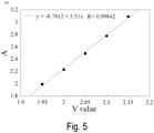
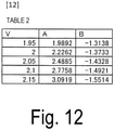
- Fig. 3 illustrates the core interval A where an inter-mode coupling of (A) -30 dB/m or more, (B) -20 dB/m or more, or (C) -10 dB/m or more occurs, and a coupling coefficient ⁇ calculated from a core configuration for acquiring the inter-mode coupling with the V value being varied, when the bend radius is 140mm and the twisting rate is 4 ⁇ rad/m in the two-core fiber.
- a wavelength is assumed to be 1550 nm.
- the relative index difference ⁇ is assumed to be 0.35% and constant.
- V value is expressed by equations below, and thus, the V value can be varied by changing parameters included in the equations below.
- the coupling coefficient ⁇ for generating the random coupling is in a range from 0.5 to 130 m -1 independently from the V value.
- the mode coupling is -20 dB/m, it is possible and more desirable to further reduce the impulse response width as described later.
- the coupling coefficient ⁇ be in a range from 2.2 to 100 m -1 independently from the V value.
- the mode coupling is -10 dB/m, it is possible and more desirable to further reduce the impulse response width.
- the coupling coefficient ⁇ be in a range from 7.3 to 79.2 m -1 independently from the V value.
- the coupling coefficient ⁇ be in a range from 0.5 to 120 m -1 even if the core has any configuration.
- the coupling coefficient ⁇ be in a range from 2.2 to 98 m -1 even if the core has any configuration.
- the coupling coefficient ⁇ be in a range from 7.3 to 77.1 m -1 even if the core has any configuration.
- Fig. 4 illustrates the core interval A where an inter-mode coupling of (A) -30 dB/m or more, (B) -20 dB/m or more, or (C) -10 dB/m or more with respect to the twisting rate occurs, and a coupling coefficient ⁇ calculated from a core configuration for acquiring the inter-mode coupling.
- the core radius a is assumed to be 4.4 ⁇ m, and the relative index difference ⁇ is assumed to be 0.35%.
- the range of the core pitch A where the random coupling occurs is constant independently from the twisting rate.
- the range of the coupling coefficient ⁇ where the random coupling occurs slightly increases as the twisting rate increases. In consideration of a twisting cycle being 4 ⁇ rad/m or more, it is only required that the coupling coefficient ⁇ for acquiring the random coupling be in a range from 0.73 to 120 m -1 . Note that details of data in Fig. 4(A) are illustrated in Table 1 in Fig. 11 . In consideration of core configuration dependency illustrated in Figs. 2(A) and 3(A) or the like, it is only required that the coupling coefficient ⁇ be in a range from 0.73 to 120 m -1 .
- the mode coupling is -20 dB/m, it is possible and more desirable to further reduce the impulse response width as described later.
- the coupling coefficient ⁇ be in a range from 2.2 to 100 m -1 .
- the coupling coefficient ⁇ be in a range from 2.2 to 98 m -1 .
- the mode coupling is -10 dB/m
- the coupling coefficient ⁇ be in a range from 6.6 to 84 m -1 .
- the coupling coefficient ⁇ be in a range from 7.3 to 77.1 m -1 .
- the multi-core optical fiber generating the random coupling independently from the core interval can be designed.
- the first embodiment describes that the core interval required for acquiring the random coupling changes depending on the core configuration such as ⁇ , but the coupling coefficient ⁇ required for acquiring the random coupling is constant.
- ⁇ required for the random coupling is ⁇ c.
- ⁇ c For example, when the mode coupling of -30 dB/m or more is acquired, 0.73 ⁇ ⁇ c ⁇ 120(m -1 ) as described in the first embodiment.
- a range of ⁇ c is ⁇ min ⁇ ⁇ c ⁇ ⁇ max .
- the core interval for acquiring the random coupling can be determined. In other words, it is only required that the core interval ⁇ satisfy the following. [Math.
- a pulse indicating a large intensity is present on both ends, and a width of the pulse is 40 ns the same as of an accumulated DMD (1 ns/km x 40 km).
- the impulse response width is the same as of the accumulated DMD.
- the impulse response shape is a Gaussian shape. It is well known that in a case that the inter-mode coupling is strong, the impulse response shape is a Gaussian shape. In the case of -20 dB/km, it can be seen that the Gaussian shape is similarly obtained, but a width thereof is further smaller.
- Fig. 8 illustrates the amount of inter-mode coupling and an impulse response 20 dB down width that are calculated. As described in the above calculation, the advantageous reduction effect of the impulse response width is observed over the coupling amount of -30 dB/m or more.
- the impulse response width thereof is proportional to a square root of the distance, which is advantageous in that the impulse response width can be reduced particularly in a long distance transmission as compared to an uncoupled fiber that is proportional to the distance.
- a cut-off wavelength should be 1.26 ⁇ m or less
- a bending loss should be 0.1 dB/100 turn or less at a wavelength of 1625 nm and a bend radius of 30 mm
- a mode field diameter should be 8.2 to 9.6 ⁇ m at a wavelength of 1310 nm.
- Fig. 9 is a diagram illustrating core configuration conditions for each core of the multi-core optical fiber to comply with G.652 (the horizontal axis represents a core radius and the vertical axis represents a relative index difference of the core).
- a region of the cut-off wavelength of 1.26 ⁇ m or less is below a curve A.
- a region of the bending loss of 0.1 dB/100 turn or less is above a curve B.
- a region of the mode field diameter of 8.2 to 9.6 ⁇ m is between a curve C and a curve D.
- the multi-core optical fiber satisfies the characteristics of G.652 and a coupling type MCF core capable of using wavelength bands from the O-band to the L-band can be attained.
- the coupling type multi-core optical fiber can be obtained that is for transmission using the desired wavelength band and has the optical characteristics complying with the international standard.
- the present invention can provide the coupling type multi-core optical fiber and the design method thereof, the coupling type multi-core optical fiber having the optical characteristics complying with the international standard in the desired wavelength band that has not been clear.
- Conceivable examples of a core arrangement of the multi-core optical fiber include a square lattice manner, a hexagonal close-packed structure, an annular manner, and the like with 2 to 19 cores, for example, as illustrated in Fig. 10 .
- the number of lengths between adjacent cores is plural, and the shortest length of the lengths is used as ⁇ .
- the present invention can achieve also a multi-core optical fiber having a trench structure in which a low refractive index clad 14 is present to surround step type cores 12 as illustrated in Fig. 13 .
- a relative index difference of the core with respect to a clad 13 is ⁇ + and a relative index difference of the low refractive index clad 14 with respect to the clad 13 is ⁇ -
- the low refractive index clad 14 is treated as an effective clad for each of the cores 12.
- the multi-core optical fiber according to the present invention can be used as a transmission medium in an optical transmission system.
- an optical cable for the optical transmission system includes the multi-core optical fiber described in the above embodiments and a sheath covering the multi-core optical fiber with the twist pitch of 500 mm or less.
Landscapes
- Physics & Mathematics (AREA)
- General Physics & Mathematics (AREA)
- Optics & Photonics (AREA)
- Optical Communication System (AREA)
- Optical Fibers, Optical Fiber Cores, And Optical Fiber Bundles (AREA)
- Optical Couplings Of Light Guides (AREA)
Applications Claiming Priority (2)
| Application Number | Priority Date | Filing Date | Title |
|---|---|---|---|
| JP2019084500A JP6715372B1 (ja) | 2019-04-25 | 2019-04-25 | マルチコア光ファイバ及び設計方法 |
| PCT/JP2020/015442 WO2020217939A1 (ja) | 2019-04-25 | 2020-04-06 | マルチコア光ファイバ及び設計方法 |
Publications (2)
| Publication Number | Publication Date |
|---|---|
| EP3961274A1 true EP3961274A1 (de) | 2022-03-02 |
| EP3961274A4 EP3961274A4 (de) | 2023-01-11 |
Family
ID=71131646
Family Applications (1)
| Application Number | Title | Priority Date | Filing Date |
|---|---|---|---|
| EP20794731.8A Pending EP3961274A4 (de) | 2019-04-25 | 2020-04-06 | Multikern-glasfaser und entwurfsverfahren |
Country Status (5)
| Country | Link |
|---|---|
| US (1) | US20220214496A1 (de) |
| EP (1) | EP3961274A4 (de) |
| JP (1) | JP6715372B1 (de) |
| CN (1) | CN113711094B (de) |
| WO (1) | WO2020217939A1 (de) |
Families Citing this family (8)
| Publication number | Priority date | Publication date | Assignee | Title |
|---|---|---|---|---|
| WO2022049735A1 (ja) * | 2020-09-04 | 2022-03-10 | 日本電信電話株式会社 | マルチコア光ファイバ |
| EP4220995A4 (de) * | 2020-09-24 | 2024-04-24 | Sumitomo Electric Industries | Mehradrige glasfaser und optisches übertragungssystem |
| WO2023113012A1 (ja) * | 2021-12-17 | 2023-06-22 | 住友電気工業株式会社 | 光ファイバケーブル |
| WO2023182227A1 (ja) * | 2022-03-24 | 2023-09-28 | 住友電気工業株式会社 | マルチコア光ファイバ |
| WO2023189621A1 (ja) * | 2022-03-30 | 2023-10-05 | 住友電気工業株式会社 | マルチコア光ファイバ |
| WO2024013876A1 (ja) * | 2022-07-13 | 2024-01-18 | 日本電信電話株式会社 | マルチコア光ファイバ及び設計方法 |
| CN115327697B (zh) * | 2022-08-17 | 2024-04-26 | 长飞光纤光缆股份有限公司 | 一种随机耦合多芯光纤及其制造方法、多芯光缆 |
| CN115455355B (zh) * | 2022-09-16 | 2023-07-25 | 苏州大学 | 一种多芯少模光纤模间串扰检测方法及装置 |
Family Cites Families (12)
| Publication number | Priority date | Publication date | Assignee | Title |
|---|---|---|---|---|
| WO2010038863A1 (ja) * | 2008-10-03 | 2010-04-08 | 国立大学法人 横浜国立大学 | 非結合系マルチコアファイバ |
| JP5708015B2 (ja) * | 2010-02-26 | 2015-04-30 | 住友電気工業株式会社 | 光ファイバケーブル |
| US9103961B2 (en) * | 2011-08-12 | 2015-08-11 | University Of Central Florida Research Foundation, Inc. | Systems and methods for optical transmission using supermodes |
| JP5522696B2 (ja) * | 2011-10-13 | 2014-06-18 | 日本電信電話株式会社 | 4芯単一モード光ファイバおよび光ケーブル |
| EP2944989A4 (de) * | 2013-01-10 | 2016-09-07 | Sumitomo Electric Industries | Optische komponente und optisches kommunikationssystem |
| JP6532748B2 (ja) * | 2015-04-30 | 2019-06-19 | 株式会社フジクラ | マルチコアファイバ |
| JP2017072818A (ja) * | 2015-10-08 | 2017-04-13 | 住友電気工業株式会社 | マルチコア光ファイバ、マルチコア光ファイバケーブルおよび光ファイバ伝送システム |
| WO2017061184A1 (ja) * | 2015-10-08 | 2017-04-13 | 住友電気工業株式会社 | マルチコア光ファイバ、マルチコア光ファイバケーブルおよび光ファイバ伝送システム |
| JP6954294B2 (ja) * | 2016-09-09 | 2021-10-27 | 住友電気工業株式会社 | 光増幅器およびマルチコア光ファイバ |
| WO2019198365A1 (ja) * | 2018-04-09 | 2019-10-17 | 住友電気工業株式会社 | マルチコア光ファイバおよびマルチコア光ファイバケーブル |
| CN109283613A (zh) * | 2018-11-26 | 2019-01-29 | 北京交通大学 | 一种低芯间串扰多芯光纤 |
| JP7326933B2 (ja) * | 2019-07-03 | 2023-08-16 | 住友電気工業株式会社 | マルチコア光ファイバ |
-
2019
- 2019-04-25 JP JP2019084500A patent/JP6715372B1/ja active Active
-
2020
- 2020-04-06 WO PCT/JP2020/015442 patent/WO2020217939A1/ja unknown
- 2020-04-06 EP EP20794731.8A patent/EP3961274A4/de active Pending
- 2020-04-06 US US17/605,758 patent/US20220214496A1/en active Pending
- 2020-04-06 CN CN202080029841.9A patent/CN113711094B/zh active Active
Also Published As
| Publication number | Publication date |
|---|---|
| CN113711094A (zh) | 2021-11-26 |
| EP3961274A4 (de) | 2023-01-11 |
| JP6715372B1 (ja) | 2020-07-01 |
| WO2020217939A1 (ja) | 2020-10-29 |
| CN113711094B (zh) | 2023-06-30 |
| US20220214496A1 (en) | 2022-07-07 |
| JP2020181106A (ja) | 2020-11-05 |
Similar Documents
| Publication | Publication Date | Title |
|---|---|---|
| EP3961274A1 (de) | Multikern-glasfaser und entwurfsverfahren | |
| EP2706387B1 (de) | Faserdesigns mit mehreren LP-Modi für Multiplex durch Modenteilung | |
| Saitoh et al. | Crosstalk and core density in uncoupled multicore fibers | |
| US8094985B2 (en) | Multi-core holey fiber and optical transmission system | |
| JP3320745B2 (ja) | 分散フラット光ファイバ | |
| EP1498753B1 (de) | Multimode-Gradientenindex-Faser und Herstellungsmethode | |
| US9020316B2 (en) | Low attenuation optical fibers with an F-graded index core | |
| JP4065716B2 (ja) | 有効面積の広い正分散光ファイバ | |
| US9128237B2 (en) | Optical fiber and optical transmission system | |
| JP6397898B2 (ja) | 空間分割多重のための少モード光ファイバ | |
| JP6611250B2 (ja) | マルチコア光ファイバ及びマルチコア光ファイバの設計方法 | |
| US5732178A (en) | Single-mode optical fiber | |
| JP6361101B2 (ja) | 光ファイバ | |
| JP6453166B2 (ja) | マルチコア光ファイバ、光ファイバの製造方法、光ファイバケーブルの製造方法 | |
| US8315494B2 (en) | Optical fiber | |
| EP2657732B1 (de) | Mehradrige Faser | |
| CN112219145B (zh) | 多芯光纤和多芯光纤缆线 | |
| EP1507154B1 (de) | Optische faser mit dispersionsverschiebung | |
| Seraji et al. | A revisit of refractive index profiles design for reduction of positive dispersion, splice loss, and enhancement of negative dispersion in optical transmission lines | |
| JP7364192B2 (ja) | マルチコア光ファイバ及び光ファイバケーブル | |
| US20030044148A1 (en) | Controlled dispersion optical fiber | |
| JP7320788B2 (ja) | 結合型マルチコア光ファイバ | |
| Sagae et al. | Solid-Type low-latency optical fiber with large effective area | |
| US20230244028A1 (en) | Optical fiber | |
| EP3492956A1 (de) | Nichtnulldispersionsverschobene faser mit geringer grenzwellenlänge und grosser effektiver fläche |
Legal Events
| Date | Code | Title | Description |
|---|---|---|---|
| STAA | Information on the status of an ep patent application or granted ep patent |
Free format text: STATUS: THE INTERNATIONAL PUBLICATION HAS BEEN MADE |
|
| PUAI | Public reference made under article 153(3) epc to a published international application that has entered the european phase |
Free format text: ORIGINAL CODE: 0009012 |
|
| STAA | Information on the status of an ep patent application or granted ep patent |
Free format text: STATUS: REQUEST FOR EXAMINATION WAS MADE |
|
| 17P | Request for examination filed |
Effective date: 20211125 |
|
| AK | Designated contracting states |
Kind code of ref document: A1 Designated state(s): AL AT BE BG CH CY CZ DE DK EE ES FI FR GB GR HR HU IE IS IT LI LT LU LV MC MK MT NL NO PL PT RO RS SE SI SK SM TR |
|
| DAV | Request for validation of the european patent (deleted) | ||
| DAX | Request for extension of the european patent (deleted) | ||
| A4 | Supplementary search report drawn up and despatched |
Effective date: 20221208 |
|
| RIC1 | Information provided on ipc code assigned before grant |
Ipc: G02B 6/02 20060101AFI20221202BHEP |
|
| STAA | Information on the status of an ep patent application or granted ep patent |
Free format text: STATUS: EXAMINATION IS IN PROGRESS |
|
| 17Q | First examination report despatched |
Effective date: 20230825 |
|
| GRAP | Despatch of communication of intention to grant a patent |
Free format text: ORIGINAL CODE: EPIDOSNIGR1 |
|
| STAA | Information on the status of an ep patent application or granted ep patent |
Free format text: STATUS: GRANT OF PATENT IS INTENDED |
|
| INTG | Intention to grant announced |
Effective date: 20240301 |