EP3958960B1 - Elektrische stimulation mit thermischer behandlung oder thermischer überwachung - Google Patents
Elektrische stimulation mit thermischer behandlung oder thermischer überwachung Download PDFInfo
- Publication number
- EP3958960B1 EP3958960B1 EP20724703.2A EP20724703A EP3958960B1 EP 3958960 B1 EP3958960 B1 EP 3958960B1 EP 20724703 A EP20724703 A EP 20724703A EP 3958960 B1 EP3958960 B1 EP 3958960B1
- Authority
- EP
- European Patent Office
- Prior art keywords
- electric field
- medical device
- field generating
- electrodes
- control circuit
- Prior art date
- Legal status (The legal status is an assumption and is not a legal conclusion. Google has not performed a legal analysis and makes no representation as to the accuracy of the status listed.)
- Active
Links
Images


Classifications
-
- A—HUMAN NECESSITIES
- A61—MEDICAL OR VETERINARY SCIENCE; HYGIENE
- A61N—ELECTROTHERAPY; MAGNETOTHERAPY; RADIATION THERAPY; ULTRASOUND THERAPY
- A61N1/00—Electrotherapy; Circuits therefor
- A61N1/18—Applying electric currents by contact electrodes
- A61N1/32—Applying electric currents by contact electrodes alternating or intermittent currents
- A61N1/36—Applying electric currents by contact electrodes alternating or intermittent currents for stimulation
- A61N1/36002—Cancer treatment, e.g. tumour
-
- A—HUMAN NECESSITIES
- A61—MEDICAL OR VETERINARY SCIENCE; HYGIENE
- A61F—FILTERS IMPLANTABLE INTO BLOOD VESSELS; PROSTHESES; DEVICES PROVIDING PATENCY TO, OR PREVENTING COLLAPSING OF, TUBULAR STRUCTURES OF THE BODY, e.g. STENTS; ORTHOPAEDIC, NURSING OR CONTRACEPTIVE DEVICES; FOMENTATION; TREATMENT OR PROTECTION OF EYES OR EARS; BANDAGES, DRESSINGS OR ABSORBENT PADS; FIRST-AID KITS
- A61F7/00—Heating or cooling appliances for medical or therapeutic treatment of the human body
- A61F7/007—Heating or cooling appliances for medical or therapeutic treatment of the human body characterised by electric heating
-
- A—HUMAN NECESSITIES
- A61—MEDICAL OR VETERINARY SCIENCE; HYGIENE
- A61N—ELECTROTHERAPY; MAGNETOTHERAPY; RADIATION THERAPY; ULTRASOUND THERAPY
- A61N1/00—Electrotherapy; Circuits therefor
- A61N1/18—Applying electric currents by contact electrodes
- A61N1/32—Applying electric currents by contact electrodes alternating or intermittent currents
- A61N1/36—Applying electric currents by contact electrodes alternating or intermittent currents for stimulation
- A61N1/36014—External stimulators, e.g. with patch electrodes
- A61N1/3603—Control systems
- A61N1/36034—Control systems specified by the stimulation parameters
-
- A—HUMAN NECESSITIES
- A61—MEDICAL OR VETERINARY SCIENCE; HYGIENE
- A61F—FILTERS IMPLANTABLE INTO BLOOD VESSELS; PROSTHESES; DEVICES PROVIDING PATENCY TO, OR PREVENTING COLLAPSING OF, TUBULAR STRUCTURES OF THE BODY, e.g. STENTS; ORTHOPAEDIC, NURSING OR CONTRACEPTIVE DEVICES; FOMENTATION; TREATMENT OR PROTECTION OF EYES OR EARS; BANDAGES, DRESSINGS OR ABSORBENT PADS; FIRST-AID KITS
- A61F7/00—Heating or cooling appliances for medical or therapeutic treatment of the human body
- A61F7/007—Heating or cooling appliances for medical or therapeutic treatment of the human body characterised by electric heating
- A61F2007/0071—Heating or cooling appliances for medical or therapeutic treatment of the human body characterised by electric heating using a resistor, e.g. near the spot to be heated
- A61F2007/0073—Heating or cooling appliances for medical or therapeutic treatment of the human body characterised by electric heating using a resistor, e.g. near the spot to be heated thermistor
-
- A—HUMAN NECESSITIES
- A61—MEDICAL OR VETERINARY SCIENCE; HYGIENE
- A61F—FILTERS IMPLANTABLE INTO BLOOD VESSELS; PROSTHESES; DEVICES PROVIDING PATENCY TO, OR PREVENTING COLLAPSING OF, TUBULAR STRUCTURES OF THE BODY, e.g. STENTS; ORTHOPAEDIC, NURSING OR CONTRACEPTIVE DEVICES; FOMENTATION; TREATMENT OR PROTECTION OF EYES OR EARS; BANDAGES, DRESSINGS OR ABSORBENT PADS; FIRST-AID KITS
- A61F7/00—Heating or cooling appliances for medical or therapeutic treatment of the human body
- A61F2007/0089—Chemotherapy developing heat
-
- A—HUMAN NECESSITIES
- A61—MEDICAL OR VETERINARY SCIENCE; HYGIENE
- A61F—FILTERS IMPLANTABLE INTO BLOOD VESSELS; PROSTHESES; DEVICES PROVIDING PATENCY TO, OR PREVENTING COLLAPSING OF, TUBULAR STRUCTURES OF THE BODY, e.g. STENTS; ORTHOPAEDIC, NURSING OR CONTRACEPTIVE DEVICES; FOMENTATION; TREATMENT OR PROTECTION OF EYES OR EARS; BANDAGES, DRESSINGS OR ABSORBENT PADS; FIRST-AID KITS
- A61F7/00—Heating or cooling appliances for medical or therapeutic treatment of the human body
- A61F2007/0095—Heating or cooling appliances for medical or therapeutic treatment of the human body with a temperature indicator
- A61F2007/0096—Heating or cooling appliances for medical or therapeutic treatment of the human body with a temperature indicator with a thermometer
-
- A—HUMAN NECESSITIES
- A61—MEDICAL OR VETERINARY SCIENCE; HYGIENE
- A61F—FILTERS IMPLANTABLE INTO BLOOD VESSELS; PROSTHESES; DEVICES PROVIDING PATENCY TO, OR PREVENTING COLLAPSING OF, TUBULAR STRUCTURES OF THE BODY, e.g. STENTS; ORTHOPAEDIC, NURSING OR CONTRACEPTIVE DEVICES; FOMENTATION; TREATMENT OR PROTECTION OF EYES OR EARS; BANDAGES, DRESSINGS OR ABSORBENT PADS; FIRST-AID KITS
- A61F7/00—Heating or cooling appliances for medical or therapeutic treatment of the human body
- A61F7/12—Devices for heating or cooling internal body cavities
- A61F2007/126—Devices for heating or cooling internal body cavities for invasive application, e.g. for introducing into blood vessels
-
- A—HUMAN NECESSITIES
- A61—MEDICAL OR VETERINARY SCIENCE; HYGIENE
- A61N—ELECTROTHERAPY; MAGNETOTHERAPY; RADIATION THERAPY; ULTRASOUND THERAPY
- A61N1/00—Electrotherapy; Circuits therefor
- A61N1/02—Details
- A61N1/04—Electrodes
- A61N1/05—Electrodes for implantation or insertion into the body, e.g. heart electrode
-
- A—HUMAN NECESSITIES
- A61—MEDICAL OR VETERINARY SCIENCE; HYGIENE
- A61N—ELECTROTHERAPY; MAGNETOTHERAPY; RADIATION THERAPY; ULTRASOUND THERAPY
- A61N1/00—Electrotherapy; Circuits therefor
- A61N1/02—Details
- A61N1/04—Electrodes
- A61N1/06—Electrodes for high-frequency therapy
-
- A—HUMAN NECESSITIES
- A61—MEDICAL OR VETERINARY SCIENCE; HYGIENE
- A61N—ELECTROTHERAPY; MAGNETOTHERAPY; RADIATION THERAPY; ULTRASOUND THERAPY
- A61N1/00—Electrotherapy; Circuits therefor
- A61N1/18—Applying electric currents by contact electrodes
- A61N1/32—Applying electric currents by contact electrodes alternating or intermittent currents
- A61N1/36—Applying electric currents by contact electrodes alternating or intermittent currents for stimulation
- A61N1/36014—External stimulators, e.g. with patch electrodes
- A61N1/36017—External stimulators, e.g. with patch electrodes with leads or electrodes penetrating the skin
-
- A—HUMAN NECESSITIES
- A61—MEDICAL OR VETERINARY SCIENCE; HYGIENE
- A61N—ELECTROTHERAPY; MAGNETOTHERAPY; RADIATION THERAPY; ULTRASOUND THERAPY
- A61N1/00—Electrotherapy; Circuits therefor
- A61N1/18—Applying electric currents by contact electrodes
- A61N1/32—Applying electric currents by contact electrodes alternating or intermittent currents
- A61N1/36—Applying electric currents by contact electrodes alternating or intermittent currents for stimulation
- A61N1/3605—Implantable neurostimulators for stimulating central or peripheral nerve system
- A61N1/36128—Control systems
- A61N1/36135—Control systems using physiological parameters
- A61N1/3614—Control systems using physiological parameters based on impedance measurement
-
- A—HUMAN NECESSITIES
- A61—MEDICAL OR VETERINARY SCIENCE; HYGIENE
- A61N—ELECTROTHERAPY; MAGNETOTHERAPY; RADIATION THERAPY; ULTRASOUND THERAPY
- A61N1/00—Electrotherapy; Circuits therefor
- A61N1/40—Applying electric fields by inductive or capacitive coupling ; Applying radio-frequency signals
- A61N1/403—Applying electric fields by inductive or capacitive coupling ; Applying radio-frequency signals for thermotherapy, e.g. hyperthermia
Definitions
- Embodiments herein relate to medical devices and exemplary methods for using the same to treat cancerous tumors within a bodily tissue.
- first-line therapies such as surgery, radiation therapy, and chemotherapy.
- second-line therapies can include radioactive seeding, cryotherapy, hormone or biologics therapy, ablation, and the like. Combinations of first-line therapies and second-line therapies can also be a benefit to patients if one particular therapy on its own is not effective.
- Cancerous tumors can form if one normal cell in any part of the body mutates and then begins to grow and multiply too much and too quickly. Cancerous tumors can be a result of a genetic mutation to the cellular DNA or RNA that arises during cell division, an external stimulus such as ionizing or non-ionizing radiation, exposure to a carcinogen, or a result of a hereditary gene mutation. Regardless of the etiology, many cancerous tumors are the result of unchecked rapid cellular division.
- US 2019/117973 A1 discloses medical device systems including electric field shaping elements for use in treating cancerous tumors within a bodily tissue.
- a method for treating a cancerous tumor is provided. The method can include implanting one or more electrodes within a patient and measuring the impedance of tissue within the patient along a vector passing through or near a cancerous tumor. The method can also include administering an electric field to the cancerous tumor of the patient based on the measured impedance.
- IMDs may store and introduce chemotherapy drugs into the body prior to electroporation therapy.
- High frequency stimulation of tissue in or around the tumor may also be provided to increase tissue temperature prior to electroporation therapy.
- delivery of the electroporation therapy may be synchronized with cardiac qRs complex. Algorithms to suspend therapy in the event of edema may also be incorporated.
- US 2016/346536 A1 discloses cells that are in the process division being vulnerable to damage by AC electric fields that have specific frequency and field strength characteristics. The selective destruction of rapidly dividing cells can therefore be accomplished by imposing an AC electric field in a target region for extended periods of time at particular frequencies with particular filed strengths.
- US 4,016,886 A discloses a method for a localized tissue heating of tumors. Localized radio frequency current fields are produced with specific electrode configurations. Several electrode configurations are disclosed, enabling variations in electrical and thermal properties of tissues to be exploited.
- EP 2 942 023 A2 discloses high-frequency ablation of tissue in the body using a cooled high-frequency electrode connected to a high frequency generator including a computer graphic control system and an automatic controller for control the signal output from the generator, and adapted to display on a real time graphic display a measured parameter related to the ablation process and visually monitor the variation of the parameter of the signal output that is controlled by the controller during the ablation process.
- One or more measured parameters may be displayed simultaneously to visually interpret the relation of their variation and values.
- the displayed one or more parameters can be taken from the list of measured voltage, current, power, impedance, electrode temperature, and tissue temperature related to the ablation process.
- US 2018/221088 A1 discloses ablation of cardiac tissue being carried out by inserting a probe having an ablation electrode and a plurality of microelectrodes into a body of a living subject to establish contact between two of the microelectrodes and target tissue, and energizing the ablation electrode. While the ablation electrode is energized impedances are measured between the microelectrodes, and the power level of the ablation electrode adjusted according to the impedances.
- a medical device system having an electric field generating circuit configured to generate one or more electric fields and a control circuit in communication with the electric field generating circuit.
- the control circuit can be configured to control delivery of the one or more electric fields from the electric field generating circuit.
- the system can include two or more electrodes to deliver the electric fields to a site of a cancerous tumor within a patient and a temperature sensor to measure the temperature of tissue at the site of the cancerous tumor, the temperature sensor in electronic communication with the control circuit.
- the control circuit can cause the electric field generating circuit to generate one or more electric fields at frequencies selected from a range of between 10 kHz to 1 MHz.
- the system can include a first lead providing electrical communication between the control circuit and at least one electrode; wherein the temperature sensor is disposed on the first lead.
- the first lead can include at least one of a transcutaneous lead and a fully implanted lead.
- At least two electrodes are configured to be implanted.
- the electric fields are delivered across at least one vector defined by an electrode pair.
- the temperature sensor is positioned between the electrode pair.
- the temperature sensor is adapted to be inserted into the cancerous tumor.
- the electric fields are delivered across at least two vectors, wherein a first vector is defined by a first pair of electrodes and a second vector is defined by a second pair of electrodes.
- the system can include at least two electric field generating circuits, wherein a first electric field generating circuit is implanted and a second electric field generating circuit is external.
- the system can further include an implanted housing, the implanted housing defining an interior volume into which the electric field generating circuit and the control circuit are disposed.
- the temperature sensor is selected from the group consisting of a thermistor, a resistance thermometer, a thermocouple, and a semi-conductor based sensor.
- a medical device system having an electric field generating circuit configured to generate one or more electric fields and a control circuit in communication with the electric field generating circuit, the control circuit configured to control delivery of the one or more electric fields from the electric field generating circuit.
- the system can include two or more electrodes forming at least one electrode pair to deliver the electric fields to a site of a cancerous tumor within a patient.
- the control circuit can cause the electric field generating circuit to generate one or more electric fields at frequencies selected from a range of between 10 kHz to 1 MHz.
- the control circuit can calculate a power output of the electric field and estimate a temperature of tissue within the electric field based on the power output and a distance between the electrodes of the electrode pair.
- the medical device system is configured to receive data regarding the distance between the electrodes of the electrode pair.
- the medical device system is configured to estimate the distance between the electrodes of the electrode pair based on impedance data.
- a medical device system having an electric field generating circuit configured to generate one or more electric fields and a control circuit in communication with the electric field generating circuit, the control circuit configured to control delivery of the one or more electric fields from the electric field generating circuit.
- the system can further include two or more electrodes forming at least one electrode pair to deliver the electric fields to a site of a cancerous tumor within a patient and wherein the control circuit causes the electric field generating circuit to generate one or more electric fields at frequencies selected from a range of between 10 kHz to 1 MHz.
- the control circuit can estimate a temperature of tissue within the electric field based on an impedance measurement.
- control circuit estimates a temperature of tissue within the electric field based on an impedance measurement and a distance between the electrodes of the electrode pair.
- the medical device system is configured to receive data regarding the distance between the electrodes of the electrode pair.
- control circuit estimates changes in temperature of tissue within the electric field based on changes in measured impedance.
- the system can further include a heating element, wherein the control circuit causes the heating element to generate heat.
- first-line therapies to treat cancerous tumors can include surgery, radiation therapy, and chemotherapy.
- first-line therapies have undesirable concomitant side effects, such as fatigue, hair loss, immunosuppression, and long surgical recovery times, to name a few.
- apoptosis i.e., programmed cell death
- alternating electric fields can lead to increased electric field density near the cleavage furrow of the dividing cells during telophase.
- An increased electric field density in the region of the cleavage furrow can result in dielectrophoresis of charged macromolecules, such as proteins and nucleic acids, toward the high electric field density at the furrow.
- the unequal concentration of key macromolecules required for cellular division at the site of the cleavage furrow can disrupt the final separation of the sister cells during telophase and eventually lead to apoptosis.
- Temperature can be in important parameter to measure during the administration of an electrical field. In some cases, it may be desirable to limit and/or prevent thermal destruction of tissues. As such, the temperature of tissue can be monitored (directly or indirectly) in order to prevent the temperature from rising to a level where the thermal destruction of tissue may occur. However, in some embodiments, a degree of heating in combination with the application of an electrical field may be therapeutic. Thus, in some embodiments, it may be desirable to apply heat to tissue.
- various embodiments disclosed herein include a medical device system that can generate an electric field for treatment of cancer that can include, or can control, at least one electrode, and/or at least one temperature sensor or at least one heating element.
- an electric field can be generated, and heat can be applied, such as via a heating element, to treat a tumor.
- a temperature sensor can be used to monitor the temperature of tissue near or around an electric field or a heating element, such as to observe changes to tissue during heating or electric field generation.
- the medical device can be configured to turn off or stop the therapy if the temperature of the tissue exceed a threshold.
- FIG. 1 a schematic view is shown of a medical device 100 in accordance with various embodiments herein.
- the medical device 100 can be implanted entirely within the body of a patient 101 at or near the site of a cancerous tumor 110 located within a bodily tissue.
- Various implant sites can be used including areas such as in the limbs, the upper torso, the abdominal area, the head, and the like.
- the medical device 200 can be external but can be connected to a component, such as leads, that are at least partially implanted within the body of a patient 101.
- the medical device 200 can be partially implanted and partially external to the body of a patient.
- the medical device 200 can include a transcutaneous connection between components disposed internal to the body and external to the body.
- the medical device system described herein can include an implanted medical device 100 and an external medical device 200. In other embodiments, the medical device system described herein can include a partially implanted medical device.
- An implanted portion of a medical device system such as an implanted medical device 100 or portion thereof, can wirelessly communicate patient identification data, diagnostic information, electric field data, physiological parameters, software updates, and the like with a fully or partially external portion of a medical device 200 over a wireless connection.
- Implanted medical device 100 can also wirelessly communicate with an external device configured to wirelessly charge the medical device utilizing inductance, radio frequency, and acoustic energy transfer techniques, and the like.
- a portion of a medical device or system can be entirely implanted, and a portion of the medical device can be entirely external.
- one or more electrodes or leads can be entirely implanted within the body, whereas the portion of the medical device that generates an electric field, such as an electric field generator, can be entirely external to the body.
- the electric field generators described can include many of the same components as and can be configured to perform many of the same functions as a pulse generator.
- the portion of the medical device that is entirely external can communicate wirelessly with the portion of the medical device that is entirely internal.
- a wired connection can be used for the implanted portion to communication with the external portion.
- the implanted medical device 100 and/or the medical device 200 can include a housing 102 and a header 104 coupled to the housing 102.
- the housing 102 can be formed of a material such as a metal, ceramic, polymer, composite, or the like.
- the housing 102, or one or more portions thereof, can be formed of titanium.
- the header 104 can be formed of various materials, but in some embodiments the header 104 can be formed of a translucent polymer such as an epoxy material. In some embodiments the header 104 can be hollow. In other embodiments the header 104 can be filled with components and/or structural materials such as epoxy or another material such that it is non-hollow.
- the header 104 and housing 102 can be surrounded by a protective casing made of durable polymeric material. In other embodiments, where a portion of a device is partially external, the header 104 and housing 102 can be surrounded by a protective casing made of one or more of a polymeric material, metallic material, and/or glass material.
- the header 104 can be coupled to one or more leads 106.
- the header 104 can serve to provide fixation of the proximal end of one or more leads 106 and electrically couple the one or more leads 106 to one or more components within the housing 102.
- the one or more leads 106 can include one or more electrodes 108 disposed along the length of the electrical leads 106.
- electrodes 108 can include electric field generating electrodes and in other embodiments electrodes 108 can include electric field sensing electrodes.
- leads 106 can include both electric field generating and electric field sensing electrodes.
- leads 106 can include any number of electrodes that are both electric field sensing and electric field generating.
- the leads 106 can include one or more conductors therein, such as metal wires, to provide electrical communication between the electrodes and a proximal end (or plug) of the lead.
- the wires can exist as single strands or fibers or can be multifibrillar such as a cable.
- the leads 106 can include a shaft, typically formed of a polymeric material or another non-conductive material, within which the conductors therein can pass.
- the proximal end of the leads 106 can be inserted into the header 104, thereby providing electrical communication between the electrodes 108 and the components inside the housing 102. It will be appreciated that while many embodiments of medical devices herein are designed to function with leads, leadless medical devices that generate electrical fields are also contemplated herein.
- the electrodes 108 can be positioned around or adjacent to a tumor 110, such as a cancerous tumor.
- the tumor 110 can be positioned within an electric field generated by the electrodes 108.
- the electric fields generated by the implanted medical device 100 and/or the medical device 200 can vary.
- the implanted medical device 100 and/or the medical device 200 can generate one or more electric fields at frequencies selected from a range of between 10 kHz to 1 MHz.
- an electric field can be applied to the site of a cancerous tumor at a specific frequency or constant frequency range.
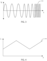
- an electric field can be applied to the site of a cancerous tumor by sweeping through a range of frequencies.
- exemplary plot 312 shows an alternating electric field, delivered by the electrodes 108, where the frequency increases over time.
- FIG. 4 shows the change in frequency as a function of time in exemplary plot 414 during a programmed therapy parameter.
- a frequency sweep can include sweeping from a minimum frequency up to a maximum frequency.
- a frequency sweep can include sweeping from a maximum frequency down to a minimum frequency.
- sweeping from a minimum frequency up to a maximum frequency and sweeping from the maximum frequency down to the minimum frequency can be repeated as many times as desired throughout the duration of the delivery of the electric field from the electric field generating circuit.
- a frequency sweep can include alternating between a first frequency sweep covering a range of about 100 kHz to 300 kHz and a second frequency sweep covering a range about 200 kHz to 500 kHz. It will be appreciated that sweeping through a first and second frequency range as described can be performed indefinitely throughout the course of the therapy.
- the second frequency sweep (range) can be at higher frequencies than the first frequency sweep (range).
- the first frequency sweep (range) can be at higher frequencies than the second frequency sweep (range).
- Frequency ranges for the first and second frequency ranges can be any range including specific frequencies recited above or below, provided that the lower end of each range is a value less than the upper end of each range. At times, it may be beneficial to have some amount of overlap between the frequency range of the first and second frequency sweep.
- the medical device 500 can include at least one electric field generating circuit configured to generate one or more electric fields.
- the electric field generating circuit can be disposed within the housing 102.
- the medical device 500 can further include control circuity that can be in communication with the electric field generating circuit.
- the control circuity can be configured to control delivery of the one or more electric fields from the electric field generating circuit.
- the control circuitry causes the electric field generating circuit to generate one or more electric fields at frequencies selected from a range of between 10 kHz to 1 MHz.
- the medical device 500 can include an implanted housing 102.
- the implanted housing 102 can define an interior volume into which the electric field generating circuit and the first control circuit are disposed.
- the medical device 500 can include one or more leads 106, such as two leads 106 (although embodiments with three, four, five, six or more leads are also directly contemplated herein).
- at least one of the leads 106 can be fully implanted or fully beneath the patient's skin 516, such as shown in FIG. 5 .
- a plurality of leads 106 are fully implanted, such as two leads 106, three leads 106, four leads 106, five leads 106, or six leads 106.
- at least two electrodes 108 are implanted and disposed on a fully implanted lead 106.
- the lead 106 can be a transcutaneous lead that extends across the patient's skin 516, such as shown in FIG. 8 .
- the medical device 500 can include two or more electrodes 108.
- the electrodes 108 can be configured to deliver the electric fields to the site of a cancerous tumor 110.
- a lead 106 can provide electrical communication between the control circuitry and at least one electrode 108.
- an electric field can be delivered across at least one vector 520 defined by a pair of electrodes 108 formed by two or more electrodes 108.
- the electric fields can be delivered across at least two vectors.
- a first vector can be defined by a first pair of electrodes and a second vector can be defined by a second pair of electrodes.
- the medical device can include at least one temperature sensor 518.
- the temperature sensor 518 can be configured to measure the temperature of tissue at the site of the tumor 110, such as to monitor temperature changes that could be a result of electric field generation or changes that could be a result of heating with a heating element.
- the temperature sensor 518 can be in electronic communication with the control circuitry.
- the medical device can include at least one temperature sensor 519 which is disposed in tissue which is not within the region being treated, such as within healthy tissue.
- the temperature sensor 519 which is remote from the treatment region, can be used along with temperature sensors 518 to determine changes in temperature that are a result of the therapy.
- the temperature sensor 518 can be selected from the group consisting of a thermistor, a resistance thermometer, a thermocouple, a semi-conductor based sensor, a bimetallic device, a thermometer, a change-of-state sensor, an optical temperature sensor (such as an infrared sensor), and the like.
- the temperature sensor 518 can be disposed on a lead 106. In some embodiments, a plurality of temperature sensors 518 can be disposed on a single lead 106. In some embodiments, at least one temperature sensor 518 is disposed on each of the leads 106. In some embodiments with multiple leads 106, at least two of the leads 106 can have a temperature sensor 518 disposed on the lead 106.
- a temperature sensor can be chronically implanted. In some embodiments, a temperature sensor can be implanted for greater than 1, 2, 4, 8, 12, 24, 52 or more weeks, or an amount falling within a range between any of the foregoing. However, in some embodiments, a temperature sensor can be transitorily implanted. In some embodiments, a temperature sensor can be implanted for less than 2 days, 1 day, 12 hours, 4 hours, 2 hours, or 1 hour, or an amount falling within a range between any of the foregoing. In some embodiments, a temperature sensor 518 can be removable, such that it can be removed after confirmation that the medical device is delivering therapy in a safe or expected manner.
- a removeable temperature sensor can be implanted during implanting of the electrodes 108.
- the removeable temperature sensor can be configured to measure the temperature of tissue near one or more electrodes, such as during implanting the of the electrodes.
- the removeable temperature sensor can be mounted on a transitorily inserted lead, introducer sheath, guide wire, delivery catheter, other type of catheter, or other type of surgical or implant instrument.
- a patient can undergo a thermal scan, such as after a medical device has been implanted.
- the thermal scan can be conducted by an external device or component.
- the thermal scan can determine temperatures of tissues in the patient's body, such as tissues near the electrodes.
- the thermal scan can allow for a less intrusive manner to monitor the temperature of various tissues within the patient's body, such as during therapy by a medical device.
- a thermal scan can be performed in various ways.
- a thermal scan can be performed using infrared thermography (IRT), an infrared thermometer, thermal imaging, thermal video, indium antimonide (InSb) devices, mercury cadmium telluride (MCT) devices, and the like.
- IRT infrared thermography
- InSb indium antimonide
- MCT mercury cadmium telluride
- control circuitry can be configured to calculate the power output of the electric field.
- the control circuit can also be configured to estimate a temperature of tissue within the electric field, such as based on the power output and the distance between the electrodes 108 of the electrode pair.
- Power in Watts
- P avg I 2 rms *R. 1 watt is equivalent to 1 joule/second.
- ⁇ T can be approximated as I 2 rms *R/mCp.
- the distance (D) between electrodes can be used as a proxy for mass.
- ⁇ T can be approximated as I 2 rms *R/DCp.
- the specific heat capacity of the tissue can be about 3.6 to 3.9 kJ kg -1 K -1 .
- the medical device 500 can be configured to receive data regarding the distance between two electrodes 108 in an electrode pair, such as to estimate the temperature of the tissue within the electric field. In some embodiments, the medical device 500 can receive data regarding the distance between two electrodes from a user. As an example, a user can enter the distance during a programming phase. In some embodiments, a user, such as a physician, can use an imaging device, such as a fluoroscope or ultrasound imaging device, to determine the distance between two electrodes 108. The data can then be entered into the medical device 500. In further embodiments, the medical device 500 can be configured to estimate the distance between the electrodes 108 of an electrode pair, such as based on impedance data between the two electrodes 108.
- control circuitry can be configured to estimate the temperature of tissue within the electric field, such as based on an impedance measurement. In some embodiments, the control circuitry can be configured to estimate the temperature of tissue within the electric field, such as based on an impedance measurement and the distance between the electrodes 108 of the electrode pair.
- the medical device 500 can be configured to receive data regarding the distance between the electrodes 108 of the electrode pair. In further embodiments, the control circuitry can be configured to estimate changes in temperature of tissue within the electric field, such as based on changes in measured impedance.
- the impedance of tissue can change as the temperature of the tissue changes. These changes in impedance can be characterized and compared to known data for the therapy device. Afterwards, the impedance measurements can be correlated to a temperature estimate of the tissue.
- the medical device 500 can include a temperature sensor 518 positioned between a pair of electrodes 108.
- the temperature sensor 518 can be adapted to be inserted into the tumor 110.
- the lead 106 which the temperature sensor 518 is disposed on does not include an electrode. In some embodiments, the lead 106 can include a plurality of temperature sensors 518.
- the therapy delivered by the medical device 500 can include generating an electric field and generating heat at the tumor 110.
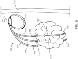
- FIG. 7 is a schematic view of a medical device 500 in accordance with various embodiments herein.
- the medical device 500 can include a heating element 722.
- the heating element 722 can be configured to generate heat.
- the heating element 722 can generate heat simultaneously with the electrodes generating an electric field.
- the heating element 722 can generate heat and cause tissue to be heated through various means.
- the heating element 722 may operate to heat tissue through conduction.
- the heating element 722 may itself heat up through joule heating (also known as Ohmic or resistive heating) which can be performed by passing an electric current through a component with electrical resistance.
- joule heating also known as Ohmic or resistive heating
- a nichrome (nickel/chromium 80/20) wire, ribbon, or strip either directly exposed or embedded within another material can be used as a heating element 722 and as it is heated it can heat the surrounding tissue through thermal conduction.
- Various other materials can also be used as a heating element.
- the heating element 722 may emit electromagnetic radiation that is then absorbed by the surrounding tissue causing it to heat up.
- the heating element 722 can include an infrared light emitter which generates electromagnetic radiation that can be absorbed the surrounding tissue raising its temperature, which can serve as an example of radiant heating.
- the heating element 722 can provide heat to tissue both through conduction and radiation.
- control circuitry causes the heating element 722 to generate heat. In some embodiments, the control circuity estimates the temperature of tissue within the electric field based on an impedance measurement. In some embodiments, the control circuitry estimates the temperature of the tissue within the electric field based on a power measurement.
- one or more heating elements 722 can be disposed on a lead 106.
- a lead 106 which includes a heating element 722 does not include an electrode 108.
- a lead 106 can include at least one heating element 722 and at least one electrode 108, such as shown in FIG. 8.
- FIG. 8 shows a schematic view of a medical device 500 in accordance with various embodiments herein.
- the medical device 500 can include a housing 102 (which can be an external housing in this example) and one or more leads 106.
- the medical device 500 can include one or more transcutaneous leads 106, such as a lead 106 that passes through or across the patient's skin 516.
- at least two electrodes 108 are implanted and disposed on a transcutaneous lead 106.
- at least two electrodes 108 are implanted and disposed on transcutaneous leads 106, such as at least one electrode 108 on two different transcutaneous leads 106.
- device operations herein may consume a significant amount of electrical power.
- joule heating may consume a significant amount of electrical power.
- the power capacity of fully implanted components may be somewhat limited (e.g., there are finite limits to the total power capacity provided by implanted batteries).
- the system may be configured to deliver power to an internal (implanted) component from an external power source.
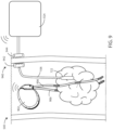
- FIG. 9 show a schematic view of a medical device 500 in accordance with various embodiments herein.
- the medical device 500 can include an implanted housing 902 and one or more fully implanted leads 906.
- the implanted leads 906 can include electrodes 108.
- the medical device 500 can include an external housing 924.
- an external power supply can be disposed within the external housing 924.
- the implanted housing 902 can be in wireless communication with the external housing 924, such as exchange data or information regarding therapy delivery.
- control circuity can be disposed in one of the implanted housing 902 or the external housing 924. In some embodiments, control circuitry can be disposed at least partially in the implanted housing 902 and the external housing 924.
- a transcutaneous lead 106 can include a wireless power transfer connection 940.
- the wireless power transfer connection 940 can be established transcutaneously between the external housing 924, such as a power supply within an external housing 924, and an implanted lead 106.
- the medical device 500 can include an inductive power transfer link, including paired internal 942 and external 944 inductors to transfer power form outside of the body to an implanted component of the system.
- the inductive power transfer link can allow for a transfer of power from an external power supply to an internal component, which in turn can cause an electrical field to be generated or heat to be generated without puncturing the skin 516 or otherwise requiring a maintained opening or tunnel through the patient's skin 516.
- the fully implanted leads 906 can include electrodes 108 and can be free of heating elements 722, and the transcutaneous lead 106 can include one or more heating elements 722.
- the external housing 924 can include a power source, such as to power the heating elements 722.
- the electric fields can be delivered across at least two vectors 520, 920.
- the first vector 520 can be defined by a first pair of electrodes 108
- the second vector 920 can be defined by a second pair of electrodes 108.
- the first vector 520 and the second vector 920 can be substantially orthogonal to one another.
- the medical device 500 can include at least two electric field generating circuits.
- a first electric field generating circuit can be implanted, such as within the housing 902
- a second electric field generating circuit can be external, such as within the housing 924.
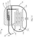
- the housing 102 can define an interior volume 1102 that can be hollow and that in some embodiments is hermetically sealed off from the area 1104 outside of medical device 1100. In other embodiments the housing 102 can be filled with components and/or structural materials such that it is non-hollow.
- the medical device 1100 can include control circuitry 1106, which can include various components 1108, 1110, 1112, 1114, 1116, and 1118 disposed within housing 102. In some embodiments, these components can be integrated and in other embodiments these components can be separate. In yet other embodiments, there can be a combination of both integrated and separate components.
- the medical device 1100 can also include an antenna 1124, to allow for unidirectional or bidirectional wireless data communication, such as with an external device or an external power supply.
- the components of medical device 1100 can include an inductive energy receiver coil (not shown) communicatively coupled or attached thereto to facilitate transcutaneous recharging of the medical device via recharging circuitry.
- control circuitry 1106 can include, but are not limited to, a microprocessor, memory circuit (such as random access memory (RAM) and/or read only memory (ROM)), recorder circuitry, controller circuit, a telemetry circuit, a power supply circuit (such as a battery), a timing circuit, and an application specific integrated circuit (ASIC), a recharging circuit, amongst others.
- Control circuitry 1106 can be in communication with an electric field generating circuit 1120 that can be configured to generate electric current to create one or more fields.
- the electric field generating circuit 1120 can be integrated with the control circuitry 1106 or can be a separate component from control circuitry 1106.
- Control circuitry 1106 can be configured to control delivery of electric current from the electric field generating circuit 1120. In some embodiments, the electric field generating circuit 1120 can be present in a portion of the medical device that is external to the body.
- control circuitry 1106 can be configured to direct the electric field generating circuit 1120 to deliver an electric field via leads 106 to the site of a cancerous tumor located within a bodily tissue. In other embodiments, the control circuitry 1106 can be configured to direct the electric field generating circuit 1120 to deliver an electric field via the housing 102 of medical device 1100 to the site of a cancerous tumor located within a bodily tissue. In other embodiments, the control circuitry 1106 can be configured to direct the electric field generating circuit 1120 to deliver an electric field between leads 106 and the housing 102 of medical device 1100. In some embodiments, one or more leads 106 can be in electrical communication with the electric field generating circuit 1120.
- various components within medical device 1100 can include an electric field sensing circuit 1122 configured to generate a signal corresponding to sensed electric fields.
- Electric field sensing circuit 1122 can be integrated with control circuitry 1106 or it can be separate from control circuitry 1106.
- Sensing electrodes can be disposed on or adjacent to the housing of the medical device, on one or more leads connected to the housing, on a separate device implanted near or in the tumor, or any combination of these locations.
- the electric field sensing circuit 1122 can include a first sensing electrode 1132 and a second sensing electrode 1134.
- the housing 102 itself can serve as a sensing electrode for the electric field sensing circuit 1122.
- the electrodes 1132 and 1134 can be in communication with the electric field sensing circuit 1122.
- the electric field sensing circuit 1122 can measure the electrical potential difference (voltage) between the first electrode 1132 and the second electrode 1134.
- the electric field sensing circuit 1122 can measure the electrical potential difference (voltage) between the first electrode 1132 or second electrode 1134, and an electrode disposed along the length of one or more leads 106. In some embodiments, the electric field sensing circuit can be configured to measure sensed electric fields and to record electric field strength in V/cm.
- the electric field sensing circuit 1122 can additionally measure an electrical potential difference between the first electrode 1132 or the second electrode 1134 and the housing 102 itself.
- the medical device can include a third electrode 1136, which can be an electric field sensing electrode or an electric field generating electrode.
- one or more sensing electrodes can be disposed along lead 106 and can serve as additional locations for sensing an electric field. Many combinations can be imagined for measuring electrical potential difference between electrodes disposed along the length of one or more leads 106 and the housing 102 in accordance with the embodiments herein.
- the one or more leads 106 can be in electrical communication with the electric field generating circuit 1120.
- the one or more leads 106 can include one or more electrodes 108, as shown in FIGS. 1 and 2 .
- various electrical conductors such as electrical conductors 1126 and 1128, can pass from the header 104 through a feed-through structure 1130 and into the interior volume 1102 of medical device 1100. As such, the electrical conductors 1126 and 1128 can serve to provide electrical communication between the one or more leads 106 and control circuitry 1106 disposed within the interior volume 1102 of the housing 102.
- recorder circuitry can be configured to record the data produced by the electric field sensing circuit 1122 and record time stamps regarding the same.
- the control circuitry 1106 can be hardwired to execute various functions, while in other embodiments the control circuitry 1106 can be directed to implement instructions executing on a microprocessor or other external computation device.
- a telemetry circuit can also be provided for communicating with external computation devices such as a programmer, a home-based unit, and/or a mobile unit (e.g. a cellular phone, personal computer, smart phone, tablet computer, and the like).
- FIG. 12 Elements of various embodiments of the medical devices described herein are shown in FIG. 12 . However, it will be appreciated that some embodiments can include additional elements beyond those shown in FIG. 12 . In addition, some embodiments may lack some elements shown in FIG. 12 .
- the medical devices as embodied herein can gather information through one or more sensing channels and can output information through one or more field generating channels.
- a microprocessor 1202 can communicate with a memory 1204 via a bidirectional data bus.
- the memory 1204 can include read only memory (ROM) or random-access memory (RAM) for program storage and RAM for data storage.
- the microprocessor 1202 can also be connected to a telemetry interface 1218 for communicating with external devices such as a programmer, a home-based unit and/or a mobile unit (e.g. a cellular phone, personal computer, smart phone, tablet computer, and the like) or directly to the cloud or another communication network as facilitated by a cellular or other data communication network.
- the medical device can include a power supply circuit 1220.
- the medical device can include an inductive energy receiver coil interface (not shown) communicatively coupled or attached thereto to facilitate transcutaneous recharging of the medical device.
- the channel interfaces 1206, 1210, and 1214 can include various components such as analog-to-digital converters for digitizing signal inputs, sensing amplifiers, registers which can be written to by the control circuitry in order to adjust the gain and threshold values for the sensing amplifiers, source drivers, modulators, demodulators, multiplexers, and the like.
- the temperature sensors 1216 are shown as part of a medical device in FIG. 12 , it is realized that in some embodiments one or more of the temperature sensors could be physically separate from the medical device. In various embodiments, one or more of the temperature sensors can be within another implanted medical device communicatively coupled to a medical device via telemetry interface 1218. In yet other embodiments, one or more of the temperature sensors can be external to the body and coupled to a medical device via telemetry interface 1218.
- a method of treating a cancerous tumor is included.
- the exemplary can include implanting at least two electrodes inside a body of a patient with the cancerous tumor, implanting a temperature sensor inside the body of the patent, generating an electrical field between at least one pair of electrodes, the electric field having frequencies within a range of between 10 kHz to 1 MHz, and sensing the temperature with the temperature sensor.
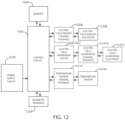
- FIG. 13 shows a flowchart depicting an exemplary method 1300 in accordance with various examples herein.
- the method 1300 can be a method for treating a cancerous tumor.
- the method 1300 can include implanting at least two electrodes inside a body of a patient with the cancerous tumor, step 1330.
- the method 1300 can further include implanting a temperature sensor inside the body of the patent, step 1332, such as near or within the cancerous tumor.
- the method 1300 can also include generating an electrical field between at least one pair of electrodes, step 1334.
- the electric field can have frequencies within a range of between 10 kHz to 1 MHz.
- the method 1300 can include sensing the temperature with the temperature sensor, step 1336, such as the temperature of the tissue near the tumor or the temperature of the tumor. In some examples, the method 1300 can include estimating the temperature of tissue within the electric field, such as based on the power output and the distance between the electrodes. In some examples, the method 1300 can include estimating the distance between electrodes of an electrode pair, such as based on impedance data.
- systems or device herein can be configured to direct an electric field generating circuit to deliver an electric field using one or more frequencies selected from a range of between 10 kHz to 1 MHz.
- the control circuitry can be configured to direct the electric field generating circuit to deliver an electric field at one or more frequencies selected from a range of between 100 kHz to 500 kHz.
- the control circuitry can be configured to direct the electric field generating circuit to deliver an electric field at one or more frequencies selected from a range of between 100 kHz to 300 kHz.
- the control circuitry can be configured to direct the electric field generating circuit to periodically deliver an electric field using one or more frequencies greater than 1 MHz.
- the electric field can be effective in disrupting cellular mitosis in cancerous cells.
- the electric field can be delivered to the site of a cancerous tumor along more than one vector.
- the electric field can be delivered along at least one vector, including at least one of the lead electrodes.
- at least two vectors with spatial diversity between the two vectors can be used.
- the vectors can be spatially and/or directionally separated (e.g., the vectors can be disposed at an angle with respect to one another) by at least about 10, 20, 30, 40, 50, 60, 70, 80 or 90 degrees.
- a desired electric field strength can be achieved by delivering an electric current between two electrodes.
- the specific current and voltage at which the electric field is delivered can vary and can be adjusted to achieve the desired electric field strength at the site of the tissue to be treated.
- the control circuitry can be configured to direct the electric field generating circuit to deliver an electric field using currents ranging from 1 mAmp to 1000 mAmp to the site of a cancerous tumor.
- the control circuitry can be configured to direct the electric field generating circuit to deliver an electric field using currents ranging from 20 mAmp to 500 mAmp to the site of a cancerous tumor.
- the control circuitry can be configured to direct the electric field generating circuit to deliver an electric field using currents ranging from 30 mAmp to 300 mAmp to the site of a cancerous tumor.
- control circuitry can be configured to direct the electric field generating circuit to deliver an electric field using currents including 1 mAmp, 2 mAmp, 3 mAmp, 4 mAmp, 5 mAmp, 6 mAmp, 7 mAmp, 8 mAmp, 9 mAmp, 10 mAmp, 15 mAmp, 20 mAmp, 25 mAmp, 30 mAmp, 35 mAmp, 40 mAmp, 45 mAmp, 50 mAmp, 60 mAmp, 70 mAmp, 80 mAmp, 90 mAmp, 100 mAmp, 125 mAmp, 150 mAmp, 175 mAmp , 200 mAmp, 225 mAmp, 250 mAmp, 275 mAmp, 300 mAmp, 325 mAmp, 350 mAmp, 375 mAmp, 400 mAmp, 425 mAmp, 450
- control circuitry can be configured to direct the electric field generating circuit to deliver an electric field at a current falling within a range, wherein any of the forgoing currents can serve as the lower or upper bound of the range, provided that the lower bound of the range is a value less than the upper bound of the range.
- control circuitry can be configured to direct the electric field generating circuit to deliver an electric field using voltages ranging from 1 V rms to 50 V rms to the site of a cancerous tumor. In some embodiments, the control circuitry can be configured to direct the electric field generating circuit to deliver an electric field using voltages ranging from 5 V rms to 30 V rms to the site of a cancerous tumor. In some embodiments, the control circuitry can be configured to direct the electric field generating circuit to deliver an electric field using voltages ranging from 10 V rms to 20 V rms to the site of a cancerous tumor.
- control circuitry can be configured to direct the electric field generating circuit to deliver an electric field using one or more voltages including 1 V rms , 2 V rms , 3 V rms , 4 V rms , 5 V rms , 6 V rms , 7 V rms , 8 V rms , 9 V rms , 10 V rms , 15 V rms , 20 V rms , 25 V rms , 30 V rms , 35 V rms , 40 V rms , 45 V rms , or 50 V rms .
- control circuitry can be configured to direct the electric field generating circuit to deliver an electric field using a voltage falling within a range, wherein any of the forgoing voltages can serve as the lower or upper bound of the range, provided that the lower bound of the range is a value less than the upper bound of the range.
- control circuitry can be configured to direct the electric field generating circuit to deliver and electric field using one or more frequencies including 10 kHz, 20 kHz, 30 kHz, 40 kHz, 50 kHz, 60 kHz, 70 kHz, 80 kHz, 90 kHz, 100 kHz, 125 kHz, 150 kHz, 175 kHz, 200 kHz, 225 kHz, 250 kHz, 275 kHz, 300 kHz, 325 kHz, 350 kHz, 375 kHz, 400 kHz, 425 kHz, 450 kHz, 475 kHz, 500 kHz, 525 kHz, 550 kHz, 575 kHz, 600 kHz, 625 kHz, 650 kHz, 675 kHz, 700 kHz, 725 kHz, 750 kHz, 775 kHz, 800 kHz, 825 kHz, 850 kHz, 875 k
- control circuitry can be configured to direct the electric field generating circuit to generate one or more applied electric field strengths selected from a range of between 0.25 V/cm to 1000 V/cm. In some embodiments, the control circuitry can be configured to direct the electric field generating circuit to generate one or more applied electric field strengths of greater than 3 V/cm. In some embodiments, the control circuitry can be configured to direct the electric field generating circuit to generate one or more applied electric field strengths selected from a range of between 1 V/cm to 10 V/cm. In some embodiments, the control circuitry can be configured to direct the electric field generating circuit to generate one or more applied electric field strengths selected from a range of between 3 V/cm to 5 V/cm.
- control circuitry can be configured to direct the electric field generating circuit to generate one or more applied electric field strengths including 0.25 V/cm, 0.5 V/cm, 0.75 V/cm, 1.0 V/cm, 2.0 V/cm, 3.0 V/cm, 5.0 V/cm, 6.0 V/cm, 7.0 V/cm, 8.0 V/cm, 9.0 V/cm, 10.0 V/cm, 20.0 V/cm, 30.0 V/cm, 40.0 V/cm, 50.0 V/cm, 60.0 V/cm, 70.0 V/cm, 80.0 V/cm, 90.0 V/cm, 100.0 V/cm, 125.0 V/cm, 150.0 V/cm, 175.0 V/cm, 200.0 V/cm, 225.0 V/cm, 250.0 V/cm, 275.0 V/cm, 300.0 V/cm, 325.0 V/cm, 350.0 V/cm, 375.0 V/cm, 400.0
- the electric field generating circuit can generate an electric field having a field strength at a treatment site falling within a range, wherein any of the foregoing field strengths can serve as the upper or lower bound of the range, provided that the upper bound is greater than the lower bound.
- the phrase “configured” describes a system, apparatus, or other structure that is constructed or configured to perform a particular task or adopt a particular configuration.
- the phrase “configured” can be used interchangeably with other similar phrases such as arranged and configured, constructed and arranged, constructed, manufactured and arranged, and the like.
Landscapes
- Health & Medical Sciences (AREA)
- Life Sciences & Earth Sciences (AREA)
- Public Health (AREA)
- Engineering & Computer Science (AREA)
- Biomedical Technology (AREA)
- Veterinary Medicine (AREA)
- Animal Behavior & Ethology (AREA)
- General Health & Medical Sciences (AREA)
- Radiology & Medical Imaging (AREA)
- Nuclear Medicine, Radiotherapy & Molecular Imaging (AREA)
- Heart & Thoracic Surgery (AREA)
- Vascular Medicine (AREA)
- Hospice & Palliative Care (AREA)
- Oncology (AREA)
- Biophysics (AREA)
- Electrotherapy Devices (AREA)
- Measuring And Recording Apparatus For Diagnosis (AREA)
- Surgical Instruments (AREA)
Claims (15)
- Medizinproduktsystem, das aufweist:eine Erzeugungsschaltung (1120) für elektrische Felder, die so konfiguriert ist, dass sie ein oder mehrere elektrische Felder erzeugt; undeine Steuerschaltung (1106) in Kommunikation mit der Erzeugungsschaltung (1120) für elektrische Felder, wobei die Steuerschaltung (1106) so konfiguriert ist, dass sie die Abgabe des einen oder der mehreren elektrischen Felder von der Erzeugungsschaltung (1120) für elektrische Felder steuert;zwei oder mehr Elektroden (108), um die elektrischen Felder zu einer Stelle eines Krebstumors in einem Patienten abzugeben;ein Heizelement (722), das auf einer Leitung (106) angeordnet ist, wobei die Steuerschaltung (1106) so konfiguriert ist, dass sie bewirkt, dass das Heizelement (722) Wärme erzeugt und eine Umgebung des Heizelements (722) über Wärmeleitung erwärmt; undeinen Temperatursensor (519), um die Temperatur von Gewebe an der Stelle des Krebstumors zu messen, wobei der Temperatursensor (519) in elektronischer Kommunikation mit der Steuerschaltung (1106) steht;wobei die Steuerschaltung (1106) bewirkt, dass die Erzeugungsschaltung (1120) für elektrische Felder ein oder mehrere elektrische Felder mit Frequenzen erzeugt, die aus einem Bereich zwischen 10 kHz bis 1 MHz ausgewählt sind.
- Medizinproduktsystem nach Anspruch 1, das ferner aufweist:eine erste Leitung (106), die für elektrische Kommunikation zwischen der Steuerschaltung (1106) und mindestens einer Elektrode (108) sorgt;wobei der Temperatursensor (519) auf der ersten Leitung (106) angeordnet ist.
- Medizinproduktsystem nach einem der Ansprüche 1 bis 2, wobei die elektrischen Felder über mindesten einen Vektor (520, 920) abgegeben werden, der durch ein Elektrodenpaar definiert ist.
- Medizinproduktsystem nach einem der Ansprüche 1 bis 3, wobei der Temperatursensor (519) zwischen dem Elektrodenpaar positioniert ist.
- Medizinproduktsystem nach einem der Ansprüche 1 bis 4, wobei die elektrischen Felder über mindesten zwei Vektoren (520, 920) abgegeben werden, wobei ein erster Vektor (520) durch ein erstes Paar Elektroden (108) definiert ist und ein zweiter Vektor (920) durch ein zweites Paar Elektroden (108) definiert ist.
- Medizinproduktsystem nach einem der Ansprüche 1 bis 5, wobei die elektrischen Felder entlang der mindesten zwei Vektoren (520, 920) räumlich und/oder direktional voneinander getrennt sind.
- Medizinproduktsystem nach einem der Ansprüche 1 bis 6, das mindestens zwei Erzeugungsschaltungen (1120) für elektrische Felder umfasst, wobei eine erste Erzeugungsschaltung (1120) für elektrische Felder implantiert ist und eine zweite Erzeugungsschaltung (1120) für elektrische Felder extern liegt.
- Medizinproduktsystem, das aufweist:eine Erzeugungsschaltung (1120) für elektrische Felder, die so konfiguriert ist, dass sie ein oder mehrere elektrische Felder erzeugt; undeine Steuerschaltung (1106) in Kommunikation mit der Erzeugungsschaltung (1120) für elektrische Felder, wobei die Steuerschaltung (1106) so konfiguriert ist, dass sie die Abgabe des einen oder der mehreren elektrischen Felder von der Erzeugungsschaltung (1120) für elektrische Felder steuert;zwei oder mehr Elektroden (108), die mindestens ein Elektrodenpaar (108) bilden, um die elektrischen Felder zu einer Stelle eines Krebstumors in einem Patienten abzugeben;ein Heizelement (722), das auf einer Leitung (106) angeordnet ist, wobei die Steuerschaltung (1106) so konfiguriert ist, dass sie bewirkt, dass das Heizelement (722) Wärme erzeugt und eine Umgebung des Heizelements (722) über Wärmeleitung erwärmt; undwobei die Steuerschaltung (1106) bewirkt, dass die Erzeugungsschaltung (1120) für elektrische Felder ein oder mehrere elektrische Felder mit Frequenzen erzeugt, die aus einem Bereich zwischen 10 kHz bis 1 MHz ausgewählt sind;wobei die Steuerschaltung (1106) eine Leistungsabgabe des elektrischen Felds berechnet und eine Temperatur von Gewebe im elektrischen Feld auf der Grundlage der Leistungsabgabe und eines Abstands zwischen den Elektroden (108) des Elektrodenpaars (108) schätzt.
- Medizinproduktsystem nach Anspruch 8, wobei das Medizinproduktsystem so konfiguriert ist, dass es Daten über den Abstand zwischen den Elektroden (108) des Elektrodenpaars (108) empfängt.
- Medizinproduktsystem nach einem der Ansprüche 8 bis 9, wobei das Medizinproduktsystem so konfiguriert ist, dass es den Abstand zwischen den Elektroden (108) des Elektrodenpaars (108) auf der Grundlage von Impedanzdaten schätzt.
- Medizinproduktsystem, das aufweist:eine Erzeugungsschaltung (1120) für elektrische Felder, die so konfiguriert ist, dass sie ein oder mehrere elektrische Felder erzeugt; undeine Steuerschaltung (1106) in Kommunikation mit der Erzeugungsschaltung (1120) für elektrische Felder, wobei die Steuerschaltung (1106) so konfiguriert ist, dass sie die Abgabe des einen oder der mehreren elektrischen Felder von der Erzeugungsschaltung (1120) für elektrische Felder steuert;zwei oder mehr Elektroden (108), die mindestens ein Elektrodenpaar (108) bilden, um die elektrischen Felder zu einer Stelle eines Krebstumors in einem Patienten abzugeben;ein Heizelement (722), das auf einer Leitung (106) angeordnet ist, wobei die Steuerschaltung (1106) so konfiguriert ist, dass sie bewirkt, dass das Heizelement (722) Wärme erzeugt und eine Umgebung des Heizelements (722) über Wärmeleitung erwärmt; undwobei die Steuerschaltung (1106) bewirkt, dass die Erzeugungsschaltung (1120) für elektrische Felder ein oder mehrere elektrische Felder mit Frequenzen erzeugt, die aus einem Bereich zwischen 10 kHz bis 1 MHz ausgewählt sind;wobei die Steuerschaltung (1106) eine Temperatur von Gewebe im elektrischen Feld auf der Grundlage einer Impedanzmessung schätzt.
- Medizinproduktsystem nach Anspruch 11, wobei die Steuerschaltung (1106) eine Temperatur von Gewebe im elektrischen Feld auf der Grundlage einer Impedanzmessung und eines Abstands zwischen den Elektroden (108) des Elektrodenpaars (108) schätzt.
- Medizinproduktsystem nach einem der Ansprüche 11 bis 12, wobei das Medizinproduktsystem so konfiguriert ist, dass es Daten über den Abstand zwischen den Elektroden (108) des Elektrodenpaars (108) empfängt.
- Medizinproduktsystem nach einem der Ansprüche 11 bis 13, wobei die Steuerschaltung (1106) Temperaturänderungen von Gewebe im elektrischen Feld auf der Grundlage von Änderungen der gemessenen Impedanz schätzt.
- Medizinproduktsystem nach einem der Ansprüche 11 bis 14, wobei das Heizelement (722) auf einer Leitung (106) angeordnet ist, die keine Elektrode (108) aufweist.
Applications Claiming Priority (2)
| Application Number | Priority Date | Filing Date | Title |
|---|---|---|---|
| US201962837416P | 2019-04-23 | 2019-04-23 | |
| PCT/US2020/029277 WO2020219521A1 (en) | 2019-04-23 | 2020-04-22 | Electrical stimulation with thermal treatment or thermal monitoring |
Publications (2)
| Publication Number | Publication Date |
|---|---|
| EP3958960A1 EP3958960A1 (de) | 2022-03-02 |
| EP3958960B1 true EP3958960B1 (de) | 2025-06-18 |
Family
ID=70614673
Family Applications (1)
| Application Number | Title | Priority Date | Filing Date |
|---|---|---|---|
| EP20724703.2A Active EP3958960B1 (de) | 2019-04-23 | 2020-04-22 | Elektrische stimulation mit thermischer behandlung oder thermischer überwachung |
Country Status (5)
| Country | Link |
|---|---|
| US (2) | US11712561B2 (de) |
| EP (1) | EP3958960B1 (de) |
| JP (1) | JP7476231B2 (de) |
| CN (1) | CN113766950A (de) |
| WO (1) | WO2020219521A1 (de) |
Families Citing this family (15)
| Publication number | Priority date | Publication date | Assignee | Title |
|---|---|---|---|---|
| US12403306B2 (en) | 2017-10-23 | 2025-09-02 | Cardiac Pacemakers, Inc. | Electric field shaping leads for treatment of cancer |
| US11338135B2 (en) | 2017-10-23 | 2022-05-24 | Cardiac Pacemakers, Inc. | Medical devices for cancer therapy with electric field shaping elements |
| EP3917423B1 (de) | 2019-02-27 | 2024-11-13 | Novocure GmbH | Abgabe von tumorbehandlungsfeldern (ttfelds) mittels implantierbarer wandleranordnungen |
| EP4378519A1 (de) | 2019-04-22 | 2024-06-05 | Boston Scientific Scimed, Inc. | Elektrische stimulationsvorrichtungen zur krebsbehandlung |
| EP3958959B1 (de) | 2019-04-22 | 2024-04-24 | Boston Scientific Scimed Inc. | Vorrichtungen zur verabreichung einer elektrischen stimulation zur behandlung von krebs |
| CN119838138A (zh) | 2019-04-22 | 2025-04-18 | 波士顿科学国际有限公司 | 对癌症的电与化学组合治疗 |
| WO2020219517A2 (en) | 2019-04-23 | 2020-10-29 | Boston Scientific Scimed, Inc. | Electrical stimulation for cancer treatment with internal and external electrodes |
| JP2022529374A (ja) | 2019-04-23 | 2022-06-21 | ボストン サイエンティフィック サイムド,インコーポレイテッド | がん治療のための電気刺激用電極 |
| WO2020219521A1 (en) | 2019-04-23 | 2020-10-29 | Boston Scientific Scimed, Inc. | Electrical stimulation with thermal treatment or thermal monitoring |
| EP4603136A3 (de) * | 2019-12-20 | 2025-11-05 | Novocure GmbH | Behandlungsanordnung zur bereitstellung von tumorbehandlungsfeldern für tiertestpatienten |
| US11883655B2 (en) | 2020-02-24 | 2024-01-30 | Boston Scientific Scimed, Inc. | Systems and methods for treatment of pancreatic cancer |
| WO2024102325A1 (en) * | 2022-11-10 | 2024-05-16 | Cardiac Pacemakers, Inc. | Implantable medical systems for cancer treatment with thermal management features |
| WO2024173737A1 (en) * | 2023-02-17 | 2024-08-22 | Cardiac Pacemakers, Inc. | Implantable medical systems for cancer treatment with electrodes for thermal management |
| WO2025038453A1 (en) * | 2023-08-15 | 2025-02-20 | Boston Scientific Scimed, Inc. | Implantable medical systems for cancer treatment with asymmetric current distribution amongst electrodes |
| WO2025202989A1 (en) * | 2024-03-29 | 2025-10-02 | Novocure Gmbh | Applying alternating electric fields to a subjects body in multiple directions, with certain directions being prioritized |
Citations (4)
| Publication number | Priority date | Publication date | Assignee | Title |
|---|---|---|---|---|
| US5928229A (en) * | 1993-11-08 | 1999-07-27 | Rita Medical Systems, Inc. | Tumor ablation apparatus |
| US20050004507A1 (en) * | 2000-03-13 | 2005-01-06 | Oncostim. Inc. | Method and device for treating cancer with electrical therapy in conjunction with chemotherapeutic agents and radiation therapy |
| US20050209640A1 (en) * | 2000-02-17 | 2005-09-22 | Yoram Palti | Treating a tumor or the like with an electric field |
| US20050240173A1 (en) * | 2002-10-02 | 2005-10-27 | Yoram Palti | Treating a tumor or the like with an electric field that is focused at a target region |
Family Cites Families (165)
| Publication number | Priority date | Publication date | Assignee | Title |
|---|---|---|---|---|
| US4016886A (en) | 1974-11-26 | 1977-04-12 | The United States Of America As Represented By The United States Energy Research And Development Administration | Method for localizing heating in tumor tissue |
| US5099838A (en) | 1988-12-15 | 1992-03-31 | Medtronic, Inc. | Endocardial defibrillation electrode system |
| US5324328A (en) | 1992-08-05 | 1994-06-28 | Siemens Pacesetter, Inc. | Conductor for a defibrillator patch lead |
| US5397342A (en) | 1993-06-07 | 1995-03-14 | Cardiac Pacemakers, Inc. | Resilient structurally coupled and electrically independent electrodes |
| US5582609A (en) | 1993-10-14 | 1996-12-10 | Ep Technologies, Inc. | Systems and methods for forming large lesions in body tissue using curvilinear electrode elements |
| US5458597A (en) | 1993-11-08 | 1995-10-17 | Zomed International | Device for treating cancer and non-malignant tumors and methods |
| DE69521308T2 (de) | 1994-04-01 | 2002-05-02 | Akzo Nobel N.V., Arnheim/Arnhem | Verwendung eines sicherheitsklemmens zur abdichtung von behältern für chemische verbindungen, und ein behälter dafür |
| US5755758A (en) | 1995-11-07 | 1998-05-26 | Medtronic, Inc. | Intramuscular stimulation lead with enhanced infection resistance |
| US7412285B2 (en) | 1999-04-09 | 2008-08-12 | Oncostim, Inc. | Method and device for treating cancer with electrical therapy in conjunction with chemotherapeutic agents and radiation therapy |
| US6366808B1 (en) | 2000-03-13 | 2002-04-02 | Edward A. Schroeppel | Implantable device and method for the electrical treatment of cancer |
| US20040215296A1 (en) | 1999-11-16 | 2004-10-28 | Barrx, Inc. | System and method for treating abnormal epithelium in an esophagus |
| US6549812B1 (en) | 1999-11-29 | 2003-04-15 | Medtronic, Inc. | Medical electrical lead having bending stiffness which increase in the distal direction |
| US6853864B2 (en) | 2000-02-02 | 2005-02-08 | Catholic University Of America, The | Use of electromagnetic fields in cancer and other therapies |
| GB0002849D0 (en) | 2000-02-08 | 2000-03-29 | Gyrus Medical Ltd | An electrosurgical instrument and an electosurgery system including such an instrument |
| US8175698B2 (en) | 2000-02-17 | 2012-05-08 | Novocure Ltd. | Treating bacteria with electric fields |
| US7146210B2 (en) | 2000-02-17 | 2006-12-05 | Standen Ltd. | Apparatus and method for optimizing tumor treatment efficiency by electric fields |
| USRE43618E1 (en) | 2000-02-17 | 2012-08-28 | Novocure Ltd | Method and apparatus for destroying dividing cells |
| US7089054B2 (en) | 2002-10-02 | 2006-08-08 | Standen Ltd. | Apparatus and method for treating a tumor or the like |
| US7136699B2 (en) | 2002-10-02 | 2006-11-14 | Standen, Ltd. | Apparatus for destroying dividing cells |
| US8447395B2 (en) | 2000-02-17 | 2013-05-21 | Novocure Ltd | Treating bacteria with electric fields |
| GB0005247D0 (en) | 2000-03-03 | 2000-04-26 | Btg Int Ltd | Electrical impedance method for differentiating tissue types |
| US6673623B1 (en) | 2000-09-12 | 2004-01-06 | Novocure, Inc. | Methods and compositions that control lipid production |
| CA2482202C (en) | 2001-04-13 | 2012-07-03 | Surgi-Vision, Inc. | Systems and methods for magnetic-resonance-guided interventional procedures |
| US7305266B1 (en) | 2001-05-14 | 2007-12-04 | Pacesetter, Inc. | Cardiac stimulation devices and methods for measuring impedances associated with the heart |
| US20020198567A1 (en) | 2001-06-07 | 2002-12-26 | Yona Keisari | Electro-endocytotic therapy as a treatment modality of cancer |
| JP2003036987A (ja) | 2001-07-24 | 2003-02-07 | Harison Toshiba Lighting Corp | 放電ランプ点灯装置、機器および画像形成装置 |
| US6909918B2 (en) | 2001-10-10 | 2005-06-21 | Medtronic, Inc. | Implantable percutaneous stimulation lead with lead carrier |
| US7653438B2 (en) | 2002-04-08 | 2010-01-26 | Ardian, Inc. | Methods and apparatus for renal neuromodulation |
| US20030204161A1 (en) | 2002-04-25 | 2003-10-30 | Bozidar Ferek-Petric | Implantable electroporation therapy device and method for using same |
| DE10255858A1 (de) | 2002-11-29 | 2004-06-17 | Evotec Oai Ag | Fluidisches Mikrosystem mit feldformenden Passivierungsschichten auf Mikroelektroden |
| US6920361B2 (en) | 2003-02-14 | 2005-07-19 | Medtronic, Inc. | Reverse wound electrodes |
| US8346482B2 (en) | 2003-08-22 | 2013-01-01 | Fernandez Dennis S | Integrated biosensor and simulation system for diagnosis and therapy |
| US8500713B2 (en) * | 2003-10-29 | 2013-08-06 | Medtronic, Inc. | Implantable electroporation therapy device and method for using same |
| US7524274B2 (en) | 2003-11-07 | 2009-04-28 | Cytyc Corporation | Tissue positioning systems and methods for use with radiation therapy |
| US7720549B2 (en) | 2004-04-06 | 2010-05-18 | Oncostim, Inc. | Partially implantable system for the electrical treatment of abnormal tissue growth |
| US20050222646A1 (en) | 2004-04-06 | 2005-10-06 | Kai Kroll | Method and device for treating cancer with modified output electrical therapy |
| US20120277839A1 (en) | 2004-09-08 | 2012-11-01 | Kramer Jeffery M | Selective stimulation to modulate the sympathetic nervous system |
| US10973570B2 (en) | 2004-09-10 | 2021-04-13 | Boston Scientific Scimed, Inc. | Apparatus and method for treatment of in-stent restenosis |
| AU2005301103A1 (en) | 2004-11-08 | 2006-05-11 | Continence Control Systems International Pty Ltd | An implantable electrode arrangement |
| EP1819394A1 (de) | 2004-11-08 | 2007-08-22 | Continence Control Systems International PTY Ltd. | Implantierbare elektrodenanordnung |
| US8409111B2 (en) | 2004-11-22 | 2013-04-02 | Bard Peripheral Vascular, Inc. | Removable localizing wire |
| ES2663782T3 (es) | 2004-12-07 | 2018-04-17 | Novocure Limited | Electrodos para aplicar un campo eléctrico in vivo durante un período de tiempo |
| ES2651812T3 (es) | 2005-06-08 | 2018-01-29 | Novocure Limited | Aparato para tratar el cáncer con campos eléctricos que se guían a las localizaciones deseadas dentro de un cuerpo |
| US8332029B2 (en) | 2005-06-28 | 2012-12-11 | Bioness Inc. | Implant system and method using implanted passive conductors for routing electrical current |
| EP3804809B1 (de) | 2005-10-03 | 2023-12-27 | Novocure GmbH | Optimierung der eigenschaften eines elektrischen felds zur erhöhung der wirkung des felds auf proliferierende zellen |
| US7616992B2 (en) | 2006-01-30 | 2009-11-10 | Medtronic, Inc. | Intravascular medical device |
| US8019414B2 (en) | 2006-04-05 | 2011-09-13 | Novocure Ltd. | Treating cancer using electromagnetic fields in combination with other treatment regimens |
| US7899555B2 (en) | 2006-04-11 | 2011-03-01 | Pacesetter, Inc. | Intrapericardial lead |
| US7809441B2 (en) | 2006-05-17 | 2010-10-05 | Cardiac Pacemakers, Inc. | Implantable medical device with chemical sensor and related methods |
| US20070270916A1 (en) | 2006-05-18 | 2007-11-22 | Fischell Robert E | Cardiac pacemaker with integrated battery |
| US20130226267A9 (en) | 2006-08-21 | 2013-08-29 | Marom Bikson | Method to reduce heating at implantable medical devices including neuroprosthetic devices |
| WO2008034103A2 (en) | 2006-09-14 | 2008-03-20 | Lazure Technologies, Llc | Device and method for destruction of cancer cells |
| CA2663762A1 (en) | 2006-09-18 | 2008-03-27 | Boston Scientific Limited | Endoprostheses |
| US8728073B2 (en) | 2006-10-10 | 2014-05-20 | Biosense Webster, Inc. | Multi-region staged inflation balloon |
| US20080208305A1 (en) | 2007-01-17 | 2008-08-28 | The Cleveland Clinic Foundation | Apparatus and methods for treating pulmonary conditions |
| US7844345B2 (en) | 2007-02-08 | 2010-11-30 | Neuropace, Inc. | Drug eluting lead systems |
| US7937147B2 (en) | 2007-02-28 | 2011-05-03 | Cardiac Pacemakers, Inc. | High frequency stimulation for treatment of atrial fibrillation |
| WO2009044289A1 (en) | 2007-03-06 | 2009-04-09 | Novocure Ltd. | Treating cancer using electromagnetic fields in combination with photodynamic therapy |
| US8376013B2 (en) | 2008-03-11 | 2013-02-19 | Duke University | Plasmonic assisted systems and methods for interior energy-activation from an exterior source |
| ES2739384T3 (es) | 2007-08-14 | 2020-01-30 | Novocure Ltd | Tratamiento de parásitos con campos eléctricos |
| WO2009036457A1 (en) | 2007-09-14 | 2009-03-19 | Lazure Technologies, Llc | Multi-layer electrode ablation probe and related methods |
| WO2009036459A1 (en) | 2007-09-14 | 2009-03-19 | Lazure Technologies, Llc | Multi-tine probe and treatment by activation of opposing tines |
| US8715203B2 (en) | 2007-09-17 | 2014-05-06 | Novocure Limited | Composite electrode |
| TWI348280B (en) | 2008-01-21 | 2011-09-01 | Univ Nat Taiwan | Dual injection locked frequency dividing circuit |
| US8180438B2 (en) | 2008-01-30 | 2012-05-15 | Greatbatch Ltd. | Minimally invasive physiologic parameter recorder and introducer system |
| US8864677B2 (en) | 2008-03-13 | 2014-10-21 | Cardiac Pacemakers, Inc. | Systems and methods for myocardial ischemia detection |
| US8968173B2 (en) | 2008-07-16 | 2015-03-03 | Frank Sivo | Methods to arrest cancer cell growth and proliferation using electromagnetic energy delivered via electromagnetic coil systems |
| US8886334B2 (en) | 2008-10-07 | 2014-11-11 | Mc10, Inc. | Systems, methods, and devices using stretchable or flexible electronics for medical applications |
| WO2010118387A1 (en) | 2009-04-09 | 2010-10-14 | Virginia Tech Intellectual Properties, Inc. | Integration of very short electric pulses for minimally to noninvasive electroporation |
| US9155885B2 (en) | 2009-04-24 | 2015-10-13 | Medtronic, Inc. | Incontinence therapy |
| TWI423738B (zh) | 2009-04-28 | 2014-01-11 | Masayuki Kumada | A method and apparatus for generating high density hollow electron cloud instantaneously by laser |
| CN102458563B (zh) | 2009-04-30 | 2014-11-26 | 麦德托尼克公司 | 屏蔽件在可植入医疗引导件内的端接 |
| US8340783B2 (en) | 2009-06-30 | 2012-12-25 | Medtronic, Inc. | Implantable medical device lead with selectively exposed electrodes and reinforcement member |
| WO2011017049A1 (en) | 2009-07-27 | 2011-02-10 | Cardiac Pacemakers, Inc. | Medical device for treating heart failure through blood volume redistribution |
| US9387323B2 (en) | 2009-09-23 | 2016-07-12 | Lake Region Manufacturing, Inc. | Guidewire-style pacing lead |
| CN101693875B (zh) | 2009-09-30 | 2012-04-18 | 重庆大学 | 基于柱状微电极阵列的细胞电融合芯片装置及电融合方法 |
| US8538538B2 (en) | 2009-11-25 | 2013-09-17 | Medtronic, Inc. | Medical electrical stimulation with implantable simulated case electrode |
| US20110238057A1 (en) | 2010-02-16 | 2011-09-29 | Angiodynamics, Inc. | Dual Bracketed Energy Delivery Probe and Method of Use |
| CN103079633B (zh) | 2010-03-11 | 2016-05-04 | 梅恩斯塔伊医疗公司 | 用于治疗背痛的模块式刺激器、植入式rf消融系统及使用方法 |
| US9526911B1 (en) | 2010-04-27 | 2016-12-27 | Lazure Scientific, Inc. | Immune mediated cancer cell destruction, systems and methods |
| EP3100696B1 (de) | 2010-10-25 | 2023-01-11 | Medtronic Ardian Luxembourg S.à.r.l. | Kathetervorrichtungen mit mehrfachelektrodenanordnungen für nierennervenmodulation |
| JP6559395B2 (ja) | 2010-12-14 | 2019-08-14 | ザ リージェンツ オブ ザ ユニバーシティ オブ カリフォルニア | 医学的障害の治療のための、頭蓋外に埋め込み可能なシステム |
| WO2012082900A2 (en) | 2010-12-15 | 2012-06-21 | Boston Scientific Neuromodulation Corporation | Systems and methods for making and using leads for electrical stimulation systems with improved rf compatibility |
| US8945207B2 (en) | 2010-12-20 | 2015-02-03 | Graftcraft I Göteborg Ab | Removable stent and method of production |
| WO2013109309A1 (en) | 2012-01-17 | 2013-07-25 | Novita Therapeutics, Llc | Expandable body device and method of use |
| EP2667929B1 (de) | 2011-01-28 | 2018-06-20 | Medtronic, Inc. | Implantierbare medizinische elektroden und systeme unter verwendung von reflexionspunkten zur steuerung von induzierter radiofrequenzenergie |
| US20120232615A1 (en) | 2011-03-07 | 2012-09-13 | Giancarlo Barolat | Modular Limb Peripheral Nerve Stimulation System and Method of Use |
| US9295404B2 (en) | 2011-03-30 | 2016-03-29 | Admittance Technologies, Inc. | Low power apparatus and method to measure complex electrical admittance or impedance |
| US20150134022A1 (en) | 2011-05-13 | 2015-05-14 | Chong Il Lee | Cell electric stimulator with separate electrodes for electrical field shaping and for stimulation |
| DE102011111649A1 (de) | 2011-08-26 | 2013-02-28 | Peter Osypka | Implantierbare Epikardiale Elektroden Anordnung |
| WO2013052590A1 (en) | 2011-10-04 | 2013-04-11 | Vessix Vascular, Inc. | Apparatus and method for treatment of in-stent restenosis |
| CN202365923U (zh) | 2011-12-07 | 2012-08-08 | 北京天助畅运医疗技术股份有限公司 | 肾神经射频消融涂层电极 |
| CA2857050A1 (en) | 2011-12-13 | 2013-06-20 | Lazure Scientific, Inc. | Control and delivery of electric fields via an electrode array |
| US9005100B2 (en) | 2011-12-15 | 2015-04-14 | The Board Of Trustees Of The Leland Stanford Jr. University | Apparatus and methods for treating pulmonary hypertension |
| CA2859989C (en) | 2011-12-23 | 2020-03-24 | Vessix Vascular, Inc. | Methods and apparatuses for remodeling tissue of or adjacent to a body passage |
| US20130261706A1 (en) | 2012-03-30 | 2013-10-03 | Neuropace, Inc. | Systems and methods for applying rapid sequential electrode stimulation |
| US8923976B2 (en) | 2012-04-26 | 2014-12-30 | Medtronic, Inc. | Movement patterns for electrical stimulation therapy |
| EP2664354B1 (de) | 2012-05-16 | 2015-09-16 | Sorin CRM SAS | Medizinische Leitung mit einer Ringelektrode zur Implantation in ein Herz- oder Hirngefäß und ein Verfahren zu deren Herstellung |
| US10195419B2 (en) | 2012-06-13 | 2019-02-05 | Mainstay Medical Limited | Electrode leads for use with implantable neuromuscular electrical stimulator |
| US9339655B2 (en) | 2012-06-30 | 2016-05-17 | Boston Scientific Neuromodulation Corporation | System and method for compounding low-frequency sources for high-frequency neuromodulation |
| US9282894B2 (en) | 2012-10-08 | 2016-03-15 | Tosense, Inc. | Internet-based system for evaluating ECG waveforms to determine the presence of p-mitrale and p-pulmonale |
| DE102013000966A1 (de) * | 2013-01-22 | 2014-07-24 | Zimmer Medizinsysteme Gmbh | Verfahren und Gerät zur kontinuierlichen, nicht invasiven Messung von Gewebetemperaturen in unterschiedlichen Gewebetiefen |
| US20170050017A1 (en) | 2013-02-25 | 2017-02-23 | Cosman Medical, Inc. | Electrosurgical System |
| EP3510919A3 (de) | 2013-03-27 | 2019-10-16 | Autonomix Medical, Inc. | Systeme zur funktionalen beurteilung und/oder modifizierung von neurologischem verkehr und/oder rezeptor |
| US20160068598A1 (en) | 2013-04-12 | 2016-03-10 | University Of Louisville Research Foundation, Inc. | Anti-cd19 compositions and methods for treating cancer |
| US9655669B2 (en) | 2013-05-06 | 2017-05-23 | Novocure Limited | Optimizing treatment using TTFields by changing the frequency during the course of long term tumor treatment |
| US10779875B2 (en) | 2013-05-06 | 2020-09-22 | Novocure Gmbh | Optimizing treatment using TTfields by changing the frequency during the course of long term tumor treatment |
| US9993656B2 (en) | 2013-06-03 | 2018-06-12 | The General Hospital Corporation | Magnetic neural stimulator and method of activation of neural tissue with same |
| US20160128767A1 (en) | 2013-06-05 | 2016-05-12 | Metavention, Inc. | Modulation of targeted nerve fibers |
| US9106004B2 (en) | 2013-12-19 | 2015-08-11 | Medtronic, Inc. | Implantable medical electrical leads and connector assemblies thereof |
| JP6600632B2 (ja) | 2013-12-27 | 2019-10-30 | モー メディカル デバイセス エルエルシー | 身体の一部への電界治療の適用 |
| US9956035B2 (en) * | 2014-03-27 | 2018-05-01 | Biosense Webster (Israel) Ltd. | Temperature measurement in catheter |
| US9717552B2 (en) * | 2014-05-06 | 2017-08-01 | Cosman Intruments, Llc | Electrosurgical generator |
| US10232167B2 (en) | 2014-05-07 | 2019-03-19 | Medtronic, Inc. | Electrode construction for implantable medical electrical leads |
| JP6594901B2 (ja) | 2014-05-12 | 2019-10-23 | バージニア テック インテレクチュアル プロパティース インコーポレイテッド | パルス電界を使用した細胞の細胞内効果の選択的調節 |
| US10265530B1 (en) | 2014-05-29 | 2019-04-23 | Stimwave Technologies Incorporated | Simulation with electrode arrays |
| US9757535B2 (en) | 2014-07-16 | 2017-09-12 | Fractyl Laboratories, Inc. | Systems, devices and methods for performing medical procedures in the intestine |
| US9833617B2 (en) | 2014-07-25 | 2017-12-05 | Loyalty Based Innovations, LLC | Apparatus and method for treating multiple tumors in patients with metastatic disease by electric fields |
| JP6621216B2 (ja) | 2014-08-27 | 2019-12-18 | ニューロナノ アーベー | 神経組織への医療機器の植込み方法 |
| CN107073271B (zh) | 2014-10-24 | 2021-06-22 | 美敦力公司 | 医疗电引线 |
| US10188863B2 (en) | 2015-02-26 | 2019-01-29 | Medtronic, Inc. | Therapy program selection for electrical stimulation therapy based on a volume of tissue activation |
| US9533163B2 (en) | 2015-02-27 | 2017-01-03 | Pacesetter, Inc. | Systems and methods for implantable medical device communication |
| WO2016142176A1 (en) | 2015-03-09 | 2016-09-15 | Koninklijke Philips N.V. | Iontophoretic device, arrangement and method |
| US20180110978A1 (en) | 2015-03-19 | 2018-04-26 | Old Dominion University Research Foundation | Synergistic regulated cell death induction with hsp90 inhibitors and nanosecond pulsed electric fields |
| CN204698678U (zh) | 2015-04-15 | 2015-10-14 | 杭州睿笛生物科技有限公司 | 纳秒脉冲肿瘤消融阵列电极 |
| WO2016168485A1 (en) | 2015-04-17 | 2016-10-20 | David Robinson | An implantable neuro-stimulation device |
| US11026746B2 (en) | 2015-05-12 | 2021-06-08 | National University Of Ireland, Galway | Devices for therapeutic nasal neuromodulation and associated methods and systems |
| WO2016179712A1 (en) | 2015-05-14 | 2016-11-17 | London Health Sciences Centre Research Inc. | Intratumoral modulation therapy |
| WO2016199142A1 (en) | 2015-06-10 | 2016-12-15 | Hadasit Medical Research Services And Development Ltd. | Implantable monitoring device |
| US10709894B2 (en) | 2015-07-01 | 2020-07-14 | Btl Medical Technologies S.R.O. | Aesthetic method of biological structure treatment by magnetic field |
| CN107847271B (zh) | 2015-08-05 | 2021-08-17 | 波士顿科学医学有限公司 | 可扩展球囊标测与消融装置 |
| WO2017044904A1 (en) | 2015-09-11 | 2017-03-16 | Nalu Medical, Inc. | Apparatus for peripheral or spinal stimulation |
| US9910453B2 (en) | 2015-09-25 | 2018-03-06 | Novocure Limited | High voltage, high efficiency sine wave generator with pre-set frequency and adjustable amplitude |
| US20170105793A1 (en) | 2015-10-15 | 2017-04-20 | Boston Scientific Scimed, Inc. | Energy delivery devices and related methods of use |
| US10188851B2 (en) | 2015-10-28 | 2019-01-29 | Novocure Limited | TTField treatment with optimization of electrode positions on the head based on MRI-based conductivity measurements |
| WO2017087945A1 (en) | 2015-11-20 | 2017-05-26 | Acea Biosciences, Inc. | Cell-substrate impedance monitoring of cancer cells |
| WO2017112665A1 (en) | 2015-12-22 | 2017-06-29 | Gupte Akshay Ashok | Systems to provide sympathetic modulation therapy |
| EP3402517B1 (de) | 2016-01-15 | 2025-08-20 | RFEMB Holdings, LLC | Immunologische behandlung von krebs unter verwendung einer tumorablationstechnik zusammen mit einer kombination eines ctla-4-inhibitors, eines pd-1-inhibitors und gm-csf |
| US10646644B2 (en) | 2016-03-15 | 2020-05-12 | CalXStars Business Accelerator, Inc. | Stimulator, pump and composition |
| WO2017173275A1 (en) | 2016-03-31 | 2017-10-05 | Cardiac Pacemakers, Inc. | Implantable medical device with rechargeable battery |
| US10821283B2 (en) | 2016-04-04 | 2020-11-03 | Novocure Gmbh | Reducing motility of cancer cells using tumor treating fields (TTFields) |
| US9925369B2 (en) | 2016-04-29 | 2018-03-27 | Pacesetter, Inc. | Retrievable intrapericardial electrotherapy lead |
| EP3429679B1 (de) | 2016-05-17 | 2022-11-23 | Boston Scientific Neuromodulation Corporation | Systeme zur verankerung einer leitung zur neurostimulation einer zielanatomie |
| KR102555691B1 (ko) | 2016-06-30 | 2023-07-13 | 노보큐어 리미티드 | 신체에 대한 종양 치료장의 길이 방향 전달을 위한 어레이들 |
| US20180008708A1 (en) | 2016-07-10 | 2018-01-11 | Novocure Limited | Synchronizing Tumor Cells to the G2/M Phase Using TTFields Combined with Taxane or Other Anti-Microtubule Agents |
| WO2018033842A1 (en) | 2016-08-18 | 2018-02-22 | Yoram Wasserman | Temperature measurement in arrays for delivering ttfields |
| WO2018106672A1 (en) | 2016-12-05 | 2018-06-14 | Old Dominion University Research Foundation | Methods and devices for treatment of tumors with nano-pulse stimulation |
| CN106823145A (zh) | 2017-03-24 | 2017-06-13 | 长沙普特斯科技有限公司 | 一种采用调幅电场治疗肿瘤的装置 |
| PL421532A1 (pl) | 2017-05-08 | 2018-11-19 | Michalczyk Marta | System do leczenia nowotworów wewnątrzczaszkowych z wykorzystaniem implantu, generującego ciągłe, zmienne pole elektryczne oraz ultradźwięki, zasilanego metodą przezskórnego transferu energii |
| US12403306B2 (en) | 2017-10-23 | 2025-09-02 | Cardiac Pacemakers, Inc. | Electric field shaping leads for treatment of cancer |
| US20190117969A1 (en) | 2017-10-23 | 2019-04-25 | Cardiac Pacemakers, Inc. | Medical devices for treatment of cancer with electric fields |
| US20190117971A1 (en) | 2017-10-23 | 2019-04-25 | Cardiac Pacemakers, Inc. | Volume-filling leads for treatment of cancer with electric fields |
| US20190117973A1 (en) | 2017-10-23 | 2019-04-25 | Cardiac Pacemakers, Inc. | Electric field cancer therapy devices with feedback mechanisms and diagnostics |
| US11338135B2 (en) | 2017-10-23 | 2022-05-24 | Cardiac Pacemakers, Inc. | Medical devices for cancer therapy with electric field shaping elements |
| EP3755416A1 (de) | 2018-02-20 | 2020-12-30 | University Of Iowa Research Foundation | Therapeutische systeme mit magnetischen und elektrischen feldern |
| KR102592927B1 (ko) | 2018-07-03 | 2023-10-20 | 에드윈 창 | 세포막 투과성을 향상시키기 위한 교류 전기장 사용 |
| CN119838138A (zh) | 2019-04-22 | 2025-04-18 | 波士顿科学国际有限公司 | 对癌症的电与化学组合治疗 |
| EP3958959B1 (de) | 2019-04-22 | 2024-04-24 | Boston Scientific Scimed Inc. | Vorrichtungen zur verabreichung einer elektrischen stimulation zur behandlung von krebs |
| EP4378519A1 (de) | 2019-04-22 | 2024-06-05 | Boston Scientific Scimed, Inc. | Elektrische stimulationsvorrichtungen zur krebsbehandlung |
| WO2020219521A1 (en) | 2019-04-23 | 2020-10-29 | Boston Scientific Scimed, Inc. | Electrical stimulation with thermal treatment or thermal monitoring |
| WO2020219517A2 (en) | 2019-04-23 | 2020-10-29 | Boston Scientific Scimed, Inc. | Electrical stimulation for cancer treatment with internal and external electrodes |
| JP2022529374A (ja) | 2019-04-23 | 2022-06-21 | ボストン サイエンティフィック サイムド,インコーポレイテッド | がん治療のための電気刺激用電極 |
| WO2020227551A1 (en) | 2019-05-09 | 2020-11-12 | Incube Labs, Llc | Anchor system for retaining a device in tissue |
| US11883655B2 (en) | 2020-02-24 | 2024-01-30 | Boston Scientific Scimed, Inc. | Systems and methods for treatment of pancreatic cancer |
| US20220296907A1 (en) | 2021-03-22 | 2022-09-22 | Cardiac Pacemakers, Inc. | Rechargeable systems for delivering electrical stimulation therapy for cancer therapy |
-
2020
- 2020-04-22 WO PCT/US2020/029277 patent/WO2020219521A1/en not_active Ceased
- 2020-04-22 JP JP2021562972A patent/JP7476231B2/ja active Active
- 2020-04-22 CN CN202080030856.7A patent/CN113766950A/zh active Pending
- 2020-04-22 EP EP20724703.2A patent/EP3958960B1/de active Active
- 2020-04-22 US US16/855,448 patent/US11712561B2/en active Active
-
2023
- 2023-07-27 US US18/227,021 patent/US20240024670A1/en active Pending
Patent Citations (4)
| Publication number | Priority date | Publication date | Assignee | Title |
|---|---|---|---|---|
| US5928229A (en) * | 1993-11-08 | 1999-07-27 | Rita Medical Systems, Inc. | Tumor ablation apparatus |
| US20050209640A1 (en) * | 2000-02-17 | 2005-09-22 | Yoram Palti | Treating a tumor or the like with an electric field |
| US20050004507A1 (en) * | 2000-03-13 | 2005-01-06 | Oncostim. Inc. | Method and device for treating cancer with electrical therapy in conjunction with chemotherapeutic agents and radiation therapy |
| US20050240173A1 (en) * | 2002-10-02 | 2005-10-27 | Yoram Palti | Treating a tumor or the like with an electric field that is focused at a target region |
Also Published As
| Publication number | Publication date |
|---|---|
| CN113766950A (zh) | 2021-12-07 |
| WO2020219521A1 (en) | 2020-10-29 |
| JP7476231B2 (ja) | 2024-04-30 |
| EP3958960A1 (de) | 2022-03-02 |
| JP2022529375A (ja) | 2022-06-21 |
| US20240024670A1 (en) | 2024-01-25 |
| US20200338346A1 (en) | 2020-10-29 |
| US11712561B2 (en) | 2023-08-01 |
Similar Documents
| Publication | Publication Date | Title |
|---|---|---|
| EP3958960B1 (de) | Elektrische stimulation mit thermischer behandlung oder thermischer überwachung | |
| EP3700623B1 (de) | Krebstherapievorrichtungen mit elektrischem feld und rückkopplungsmechanismen sowie diagnose | |
| US12186553B2 (en) | Electrical stimulation for cancer treatment with internal and external electrodes | |
| EP3700626B2 (de) | Medizinische vorrichtungen zur krebstherapie mit elementen zur formung eines elektrischen feldes | |
| EP3700621B1 (de) | Medizinische vorrichtungen zur behandlung von krebs mit elektrischen feldern | |
| CN113747936B (zh) | 用于电刺激来治疗癌症的电极 | |
| EP4110455B1 (de) | Systeme zur behandlung von bauchspeicheldrüsenkrebs | |
| EP3700451B1 (de) | Volumenfüllungselektroden zur behandlung von krebs mit elektrischen feldern | |
| EP3700627B2 (de) | Ein elektrisches feld formende elektrode zur behandlung von krebs | |
| US20250058104A1 (en) | Implantable medical systems for cancer treatment with asymmetric current distribution amongst electrodes | |
| US20240189580A1 (en) | Stimulation leads and systems for cancer treatment with low resistance and heat generation | |
| US20250073462A1 (en) | Implantable medical systems for cancer treatment with activation energy based therapy modulation |
Legal Events
| Date | Code | Title | Description |
|---|---|---|---|
| STAA | Information on the status of an ep patent application or granted ep patent |
Free format text: STATUS: UNKNOWN |
|
| STAA | Information on the status of an ep patent application or granted ep patent |
Free format text: STATUS: THE INTERNATIONAL PUBLICATION HAS BEEN MADE |
|
| PUAI | Public reference made under article 153(3) epc to a published international application that has entered the european phase |
Free format text: ORIGINAL CODE: 0009012 |
|
| STAA | Information on the status of an ep patent application or granted ep patent |
Free format text: STATUS: REQUEST FOR EXAMINATION WAS MADE |
|
| 17P | Request for examination filed |
Effective date: 20211123 |
|
| AK | Designated contracting states |
Kind code of ref document: A1 Designated state(s): AL AT BE BG CH CY CZ DE DK EE ES FI FR GB GR HR HU IE IS IT LI LT LU LV MC MK MT NL NO PL PT RO RS SE SI SK SM TR |
|
| DAV | Request for validation of the european patent (deleted) | ||
| DAX | Request for extension of the european patent (deleted) | ||
| STAA | Information on the status of an ep patent application or granted ep patent |
Free format text: STATUS: EXAMINATION IS IN PROGRESS |
|
| 17Q | First examination report despatched |
Effective date: 20240604 |
|
| GRAP | Despatch of communication of intention to grant a patent |
Free format text: ORIGINAL CODE: EPIDOSNIGR1 |
|
| STAA | Information on the status of an ep patent application or granted ep patent |
Free format text: STATUS: GRANT OF PATENT IS INTENDED |
|
| INTG | Intention to grant announced |
Effective date: 20250117 |
|
| RAP3 | Party data changed (applicant data changed or rights of an application transferred) |
Owner name: BOSTON SCIENTIFIC SCIMED, INC. |
|
| GRAS | Grant fee paid |
Free format text: ORIGINAL CODE: EPIDOSNIGR3 |
|
| GRAA | (expected) grant |
Free format text: ORIGINAL CODE: 0009210 |
|
| STAA | Information on the status of an ep patent application or granted ep patent |
Free format text: STATUS: THE PATENT HAS BEEN GRANTED |
|
| AK | Designated contracting states |
Kind code of ref document: B1 Designated state(s): AL AT BE BG CH CY CZ DE DK EE ES FI FR GB GR HR HU IE IS IT LI LT LU LV MC MK MT NL NO PL PT RO RS SE SI SK SM TR |
|
| REG | Reference to a national code |
Ref country code: GB Ref legal event code: FG4D |
|
| REG | Reference to a national code |
Ref country code: CH Ref legal event code: EP |
|
| REG | Reference to a national code |
Ref country code: DE Ref legal event code: R096 Ref document number: 602020052918 Country of ref document: DE |
|
| REG | Reference to a national code |
Ref country code: CH Ref legal event code: EP |
|
| REG | Reference to a national code |
Ref country code: IE Ref legal event code: FG4D |
|
| REG | Reference to a national code |
Ref country code: NL Ref legal event code: FP |
|
| PG25 | Lapsed in a contracting state [announced via postgrant information from national office to epo] |
Ref country code: FI Free format text: LAPSE BECAUSE OF FAILURE TO SUBMIT A TRANSLATION OF THE DESCRIPTION OR TO PAY THE FEE WITHIN THE PRESCRIBED TIME-LIMIT Effective date: 20250618 |
|
| REG | Reference to a national code |
Ref country code: LT Ref legal event code: MG9D |
|
| PG25 | Lapsed in a contracting state [announced via postgrant information from national office to epo] |
Ref country code: NO Free format text: LAPSE BECAUSE OF FAILURE TO SUBMIT A TRANSLATION OF THE DESCRIPTION OR TO PAY THE FEE WITHIN THE PRESCRIBED TIME-LIMIT Effective date: 20250918 Ref country code: GR Free format text: LAPSE BECAUSE OF FAILURE TO SUBMIT A TRANSLATION OF THE DESCRIPTION OR TO PAY THE FEE WITHIN THE PRESCRIBED TIME-LIMIT Effective date: 20250919 |
|
| PG25 | Lapsed in a contracting state [announced via postgrant information from national office to epo] |
Ref country code: BG Free format text: LAPSE BECAUSE OF FAILURE TO SUBMIT A TRANSLATION OF THE DESCRIPTION OR TO PAY THE FEE WITHIN THE PRESCRIBED TIME-LIMIT Effective date: 20250618 |
|
| PG25 | Lapsed in a contracting state [announced via postgrant information from national office to epo] |
Ref country code: HR Free format text: LAPSE BECAUSE OF FAILURE TO SUBMIT A TRANSLATION OF THE DESCRIPTION OR TO PAY THE FEE WITHIN THE PRESCRIBED TIME-LIMIT Effective date: 20250618 |
|
| PG25 | Lapsed in a contracting state [announced via postgrant information from national office to epo] |
Ref country code: RS Free format text: LAPSE BECAUSE OF FAILURE TO SUBMIT A TRANSLATION OF THE DESCRIPTION OR TO PAY THE FEE WITHIN THE PRESCRIBED TIME-LIMIT Effective date: 20250918 |
|
| PG25 | Lapsed in a contracting state [announced via postgrant information from national office to epo] |
Ref country code: LV Free format text: LAPSE BECAUSE OF FAILURE TO SUBMIT A TRANSLATION OF THE DESCRIPTION OR TO PAY THE FEE WITHIN THE PRESCRIBED TIME-LIMIT Effective date: 20250618 |
|
| PG25 | Lapsed in a contracting state [announced via postgrant information from national office to epo] |
Ref country code: PT Free format text: LAPSE BECAUSE OF FAILURE TO SUBMIT A TRANSLATION OF THE DESCRIPTION OR TO PAY THE FEE WITHIN THE PRESCRIBED TIME-LIMIT Effective date: 20251020 |
|
| REG | Reference to a national code |
Ref country code: AT Ref legal event code: MK05 Ref document number: 1803665 Country of ref document: AT Kind code of ref document: T Effective date: 20250618 |