EP3958409A1 - Electrical connector with recordable position assurance - Google Patents
Electrical connector with recordable position assurance Download PDFInfo
- Publication number
- EP3958409A1 EP3958409A1 EP21202265.1A EP21202265A EP3958409A1 EP 3958409 A1 EP3958409 A1 EP 3958409A1 EP 21202265 A EP21202265 A EP 21202265A EP 3958409 A1 EP3958409 A1 EP 3958409A1
- Authority
- EP
- European Patent Office
- Prior art keywords
- connector
- housing
- feature
- receptacle
- exposed
- Prior art date
- Legal status (The legal status is an assumption and is not a legal conclusion. Google has not performed a legal analysis and makes no representation as to the accuracy of the status listed.)
- Pending
Links
- 230000013011 mating Effects 0.000 claims abstract description 73
- 230000000007 visual effect Effects 0.000 claims abstract description 57
- 239000004020 conductor Substances 0.000 claims description 16
- 230000000295 complement effect Effects 0.000 claims description 5
- 230000007246 mechanism Effects 0.000 description 11
- 238000000034 method Methods 0.000 description 6
- 238000004519 manufacturing process Methods 0.000 description 4
- 239000011159 matrix material Substances 0.000 description 3
- 239000000463 material Substances 0.000 description 2
- 238000005259 measurement Methods 0.000 description 2
- 238000012986 modification Methods 0.000 description 2
- 230000004048 modification Effects 0.000 description 2
- 230000005540 biological transmission Effects 0.000 description 1
- 239000003086 colorant Substances 0.000 description 1
- 238000007373 indentation Methods 0.000 description 1
- 230000003287 optical effect Effects 0.000 description 1
- 230000000284 resting effect Effects 0.000 description 1
- 230000008054 signal transmission Effects 0.000 description 1
- 239000007787 solid Substances 0.000 description 1
- 230000007704 transition Effects 0.000 description 1
- 238000012795 verification Methods 0.000 description 1
Images


Classifications
-
- H—ELECTRICITY
- H01—ELECTRIC ELEMENTS
- H01R—ELECTRICALLY-CONDUCTIVE CONNECTIONS; STRUCTURAL ASSOCIATIONS OF A PLURALITY OF MUTUALLY-INSULATED ELECTRICAL CONNECTING ELEMENTS; COUPLING DEVICES; CURRENT COLLECTORS
- H01R13/00—Details of coupling devices of the kinds covered by groups H01R12/70 or H01R24/00 - H01R33/00
- H01R13/40—Securing contact members in or to a base or case; Insulating of contact members
- H01R13/42—Securing in a demountable manner
- H01R13/436—Securing a plurality of contact members by one locking piece or operation
-
- H—ELECTRICITY
- H01—ELECTRIC ELEMENTS
- H01R—ELECTRICALLY-CONDUCTIVE CONNECTIONS; STRUCTURAL ASSOCIATIONS OF A PLURALITY OF MUTUALLY-INSULATED ELECTRICAL CONNECTING ELEMENTS; COUPLING DEVICES; CURRENT COLLECTORS
- H01R13/00—Details of coupling devices of the kinds covered by groups H01R12/70 or H01R24/00 - H01R33/00
- H01R13/46—Bases; Cases
- H01R13/465—Identification means, e.g. labels, tags, markings
-
- H—ELECTRICITY
- H01—ELECTRIC ELEMENTS
- H01R—ELECTRICALLY-CONDUCTIVE CONNECTIONS; STRUCTURAL ASSOCIATIONS OF A PLURALITY OF MUTUALLY-INSULATED ELECTRICAL CONNECTING ELEMENTS; COUPLING DEVICES; CURRENT COLLECTORS
- H01R13/00—Details of coupling devices of the kinds covered by groups H01R12/70 or H01R24/00 - H01R33/00
- H01R13/62—Means for facilitating engagement or disengagement of coupling parts or for holding them in engagement
- H01R13/629—Additional means for facilitating engagement or disengagement of coupling parts, e.g. aligning or guiding means, levers, gas pressure electrical locking indicators, manufacturing tolerances
- H01R13/62933—Comprising exclusively pivoting lever
- H01R13/6295—Pivoting lever comprising means indicating incorrect coupling of mating connectors
-
- H—ELECTRICITY
- H01—ELECTRIC ELEMENTS
- H01R—ELECTRICALLY-CONDUCTIVE CONNECTIONS; STRUCTURAL ASSOCIATIONS OF A PLURALITY OF MUTUALLY-INSULATED ELECTRICAL CONNECTING ELEMENTS; COUPLING DEVICES; CURRENT COLLECTORS
- H01R13/00—Details of coupling devices of the kinds covered by groups H01R12/70 or H01R24/00 - H01R33/00
- H01R13/62—Means for facilitating engagement or disengagement of coupling parts or for holding them in engagement
- H01R13/629—Additional means for facilitating engagement or disengagement of coupling parts, e.g. aligning or guiding means, levers, gas pressure electrical locking indicators, manufacturing tolerances
- H01R13/62933—Comprising exclusively pivoting lever
- H01R13/62955—Pivoting lever comprising supplementary/additional locking means
-
- H—ELECTRICITY
- H01—ELECTRIC ELEMENTS
- H01R—ELECTRICALLY-CONDUCTIVE CONNECTIONS; STRUCTURAL ASSOCIATIONS OF A PLURALITY OF MUTUALLY-INSULATED ELECTRICAL CONNECTING ELEMENTS; COUPLING DEVICES; CURRENT COLLECTORS
- H01R13/00—Details of coupling devices of the kinds covered by groups H01R12/70 or H01R24/00 - H01R33/00
- H01R13/64—Means for preventing incorrect coupling
- H01R13/641—Means for preventing incorrect coupling by indicating incorrect coupling; by indicating correct or full engagement
-
- H—ELECTRICITY
- H01—ELECTRIC ELEMENTS
- H01R—ELECTRICALLY-CONDUCTIVE CONNECTIONS; STRUCTURAL ASSOCIATIONS OF A PLURALITY OF MUTUALLY-INSULATED ELECTRICAL CONNECTING ELEMENTS; COUPLING DEVICES; CURRENT COLLECTORS
- H01R13/00—Details of coupling devices of the kinds covered by groups H01R12/70 or H01R24/00 - H01R33/00
- H01R13/62—Means for facilitating engagement or disengagement of coupling parts or for holding them in engagement
- H01R13/629—Additional means for facilitating engagement or disengagement of coupling parts, e.g. aligning or guiding means, levers, gas pressure electrical locking indicators, manufacturing tolerances
- H01R13/62933—Comprising exclusively pivoting lever
- H01R13/62938—Pivoting lever comprising own camming means
-
- H—ELECTRICITY
- H01—ELECTRIC ELEMENTS
- H01R—ELECTRICALLY-CONDUCTIVE CONNECTIONS; STRUCTURAL ASSOCIATIONS OF A PLURALITY OF MUTUALLY-INSULATED ELECTRICAL CONNECTING ELEMENTS; COUPLING DEVICES; CURRENT COLLECTORS
- H01R2201/00—Connectors or connections adapted for particular applications
- H01R2201/26—Connectors or connections adapted for particular applications for vehicles
Definitions
- the subject matter herein relates generally to electrical connector systems.
- Some electrical connector systems and/or components thereof include a recordable feature that is used to record and log a presence, position, characteristic, or the like of the connector system during a manufacturing process or an assembly process. For example, a characteristic may be recorded that indicates whether a first connector is mated to a complementary second connector. It may be useful to record that the first and second connectors are mated to verify that such a connection has been made in the assembly process and/or to verify the presence of the first and second connectors in a larger product that is being assembled, such as an automobile or an appliance. Such data may be stored in a database.
- the portion of the indicating feature that includes the barcode label 112 is at least one of exposed or exposable in the exposed position such that the barcode label 112 is viewable and readable by the sensor 114. In the exposed position, all of the information contained in the barcode label 112 may be readable by the sensor 114.
- the indicating feature is in the exposed position relative to the concealing feature only when the housing 118 is fully mated to the second connector 104. When the housing 118 is not fully mated to the second connector 104, the indicating feature is in the concealed position relative to the concealing feature.
- Figure 4 is a top perspective view of the first connector 102 according to the embodiment shown in Figure 3 with the lever 134 in the closed position.
- the second connector 104 (shown in Figure 3 ) is not shown in Figure 3 , although it is recognized that the lever 134 in the closed position indicates that the first connector 102 is fully mated to the second connector 104. Therefore, it is assumed in the following description of Figure 4 that the first and second connectors 102, 104 are fully mated to one another.
- Figure 5 is a rear perspective view of the lever 134 of the first connector 102 according to an embodiment.
- the lever 134 is shown in the open position, and the CPA element 162 is shown in the concealed position.
- the CPA element 162 is coupled to a rear side 180 of the handle 148.
- the barcode label 112 is shown in phantom because it is disposed on the first or front side 168 (shown in Figure 3 ) of the CPA element 162.
- the barcode label 112 does not align with the window 172 of the handle 148 when the CPA element 162 is in the concealed position as shown.
- the barcode label 112 is disposed between the window 172 and the second end 176 of the handle 148.
- the CPA element 162 is configured to be moved in the revealing direction 178 towards the first end 174 of the handle 148 in order for the barcode label 112 to align with the window 172.
- the CPA element 162 may be held between two lugs 182 or rails that project from the rear side 180.
- the lugs 182 may extend partially around a second or rear side 186 of the CPA element 162 to hold the CPA element 162 in abutment with, or at least proximate to, the rear side 180 of the handle 148.
- the base portion 164 may include laterally-extending fingers 184 that engage the lugs 182 to prevent the CPA element 162 from falling off of the handle 148.
- the handle 148 defines two deflectable tabs 188 that are biased to extend at least partially rearward from the rear side 180 of the handle 148.
- the barcode label 112 aligns with and is exposed through the window 172 of the handle 148.
- the barcode label 112 is able to be viewed and read by the sensor 114 (shown in Figure 2 ) through the window.
- the barcode label 112 in the illustrated embodiment is a one-dimensional barcode that includes a series of parallel lines with spaces therebetween. The number, width, and arrangement of the lines and spaces convey specific information. The information may identify the first connector 102 and/or the connector system 100 (shown in Figure 3 ), such as by providing a part number, a manufacturer, a part name, or the like.
- the barcode label 112 is disposed on an inner surface (not shown) of the lever 134, such that an arm of the lever 134 defines the indicating feature, instead of the barcode label 112 being located on the housing 118 as shown in Figures 6 and7.
- the housing 118 defines the concealing feature.
- the barcode label 112 may be disposed on a tab or portion of the lever 134 that aligns with and faces a side of the housing 118 when the lever 134 is in the open position.
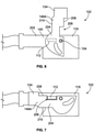
- the CPA element 214 extends over the barcode label 112 to define the concealing feature that conceals the barcode label 112 when the housing 118 is not fully mated to the mating connector (for example, the second connector 104).
- the CPA element 214 is configured to engage the second connector 104 and to slide relative to the housing 118 in a revealing direction 216 to expose the barcode label 112 when the housing 118 is fully mated to the second connector 104.
- the CPA element 214 provides position assurance because the CPA element 214 only slides relative to the housing 118 when the housing 118 is fully mated to the second connector 104.
- the CPA element 214 is referred to below as a slidable insert 214.
- the revealing direction 216 extends away from the mating end 126 of the housing 118 towards the top wall 136.
- the housing 124 of the second connector 104 in an embodiment includes at least one lug 226 that projects from a corresponding wall 228 of the housing 124 that abuts or at least faces the slidable insert 214.
- two lugs 226 are shown in phantom as the lugs 226 are located on an inner surface of the wall 228 that is not visible.
- Figure 13 is a top perspective view of the first connector 102 shown in Figure 12 .
- the top wall 136 of the housing 118 is in the revealed position relative to the CPA element 280.
- the CPA element 280 has been moved in the revealing direction 288 from the initial location shown in Figure 12 to the final location shown in Figure 13 to reveal the barcode label 112 that is disposed on the top wall 136.
- a ledge 290 of CPA element 280 extends over a portion of the handle 148 of the lever 134 to mechanically block the lever 134 from rotating from the closed position towards the open position.
- the ledge 290 extends over a second tab 292 (shown in more detail in Figure 12 ) that projects from the handle 148.
- the CPA element 280 provides a lock that holds the lever 134 in the closed position.
- the deflectable latch 284 (or a different latch) of the CPA element 280 may be configured to engage a second catch surface 294 of the housing 118 when the CPA element 280 is in the position shown in Figure 13 to prohibit the CPA element 280 from inadvertently being moved relative to the housing 118 in a concealing direction 296 that is opposite the revealing direction 288.
- an electrical connector having recordable position assurance comprising: a housing having a mating interface configured to engage a complementary mating connector during a mating operation; at least one electrical conductor held in the housing; an indicating feature carried by the housing, the indicating feature having a visual identifier disposed thereon; and a concealing feature carried by the housing, wherein the indicating feature and the concealing feature are movable relative to each other between a concealed position and an exposed position, the concealing feature concealing at least a portion of the visual identifier in the concealed position, the visual identifier being at least one of exposed or exposable in the exposed position; wherein the indicating feature is in the concealed position relative to the concealing feature when the housing is not fully mated relative to the mating connector, and the indicating feature is in the exposed position relative to the concealing feature when the housing is fully mated to the mating connector.
- the visual identifier identifies the electrical connector, the visual identifier being machine-readable such that the visual identifier is able to be read by a sensor when the visual identifier is exposed in the exposed position of the indicating feature relative to the concealing feature.
- the indicating feature is a connector position assurance (CPA) element that the visual identifier is disposed thereon, the CPA element being coupled to the lever and movable relative to the lever, the visual identifier being concealed by a segment of the lever when the CPA element is in the concealed position relative to the lever, the visual identifier being exposable at least one of through a window defined in the segment or outside a perimeter of the segment when the CPA element is in the exposed position relative to the lever.
- CPA connector position assurance
Landscapes
- Details Of Connecting Devices For Male And Female Coupling (AREA)
- Connector Housings Or Holding Contact Members (AREA)
Applications Claiming Priority (3)
| Application Number | Priority Date | Filing Date | Title |
|---|---|---|---|
| US14/950,599 US9583860B1 (en) | 2015-11-24 | 2015-11-24 | Electrical connector with recordable position assurance |
| PCT/US2016/063058 WO2017091500A1 (en) | 2015-11-24 | 2016-11-21 | Electrical connector with recordable position assurance |
| EP16805706.5A EP3381091B1 (en) | 2015-11-24 | 2016-11-21 | Electrical connector with recordable position assurance |
Related Parent Applications (2)
| Application Number | Title | Priority Date | Filing Date |
|---|---|---|---|
| EP16805706.5A Division EP3381091B1 (en) | 2015-11-24 | 2016-11-21 | Electrical connector with recordable position assurance |
| EP16805706.5A Division-Into EP3381091B1 (en) | 2015-11-24 | 2016-11-21 | Electrical connector with recordable position assurance |
Publications (1)
| Publication Number | Publication Date |
|---|---|
| EP3958409A1 true EP3958409A1 (en) | 2022-02-23 |
Family
ID=57472118
Family Applications (2)
| Application Number | Title | Priority Date | Filing Date |
|---|---|---|---|
| EP16805706.5A Active EP3381091B1 (en) | 2015-11-24 | 2016-11-21 | Electrical connector with recordable position assurance |
| EP21202265.1A Pending EP3958409A1 (en) | 2015-11-24 | 2016-11-21 | Electrical connector with recordable position assurance |
Family Applications Before (1)
| Application Number | Title | Priority Date | Filing Date |
|---|---|---|---|
| EP16805706.5A Active EP3381091B1 (en) | 2015-11-24 | 2016-11-21 | Electrical connector with recordable position assurance |
Country Status (10)
| Country | Link |
|---|---|
| US (1) | US9583860B1 (ko) |
| EP (2) | EP3381091B1 (ko) |
| JP (3) | JP6602978B2 (ko) |
| KR (3) | KR102109135B1 (ko) |
| CN (3) | CN112086813B (ko) |
| BR (1) | BR112018010194A8 (ko) |
| CA (1) | CA3005758C (ko) |
| DE (1) | DE202016008846U1 (ko) |
| MX (1) | MX2018006284A (ko) |
| WO (1) | WO2017091500A1 (ko) |
Families Citing this family (43)
| Publication number | Priority date | Publication date | Assignee | Title |
|---|---|---|---|---|
| US9748695B2 (en) * | 2014-04-30 | 2017-08-29 | Ford Global Technologies, Llc | High voltage connector assembly |
| US9583860B1 (en) * | 2015-11-24 | 2017-02-28 | Te Connectivity Corporation | Electrical connector with recordable position assurance |
| US9748693B1 (en) * | 2016-02-10 | 2017-08-29 | Yazaki North America, Inc. | Connector position assurance with identification feature |
| US9905953B1 (en) | 2016-09-30 | 2018-02-27 | Slobodan Pavlovic | High power spring-actuated electrical connector |
| WO2019082453A1 (ja) * | 2017-10-26 | 2019-05-02 | オリンパス株式会社 | コネクタ装置及びこのコネクタ装置を備えた内視鏡装置 |
| BR112020009997B1 (pt) * | 2017-11-28 | 2023-05-09 | Commscope Technologies Llc | Elemento de indício, sistema de elemento de indício para sistema de telecomunicações e sistema de telecomunicações |
| CN115832744A (zh) | 2018-02-26 | 2023-03-21 | 伊顿智能动力有限公司 | 用于高功率应用的弹簧致动式电连接器 |
| EP3776748A4 (en) * | 2018-03-29 | 2022-01-26 | CommScope Technologies LLC | SIGNS AND METHODS OF IDENTIFICATION OF TELECOMMUNICATIONS COMPONENTS |
| US10651586B2 (en) * | 2018-06-01 | 2020-05-12 | Tyco Electronics Brasil Ltda | Electrical connector with machine-readable graphic identifier |
| CN112956085B (zh) | 2018-06-07 | 2023-09-15 | 皇家精密制品有限责任公司 | 具有内部弹簧部件的电连接器系统及其应用 |
| CN109119819B (zh) * | 2018-08-25 | 2024-04-19 | 广州知崇新能源科技有限公司 | 金属弯头高压连接器 |
| USD916044S1 (en) | 2018-10-19 | 2021-04-13 | Commscope Technologies Llc | Telecommunications enclosure |
| DE102018009478A1 (de) * | 2018-12-04 | 2020-06-04 | Kostal Kontakt Systeme Gmbh | Steckverbinderanordnung |
| CN113508498A (zh) | 2019-01-21 | 2021-10-15 | 皇家精密制品有限责任公司 | 具有无螺栓汇流排系统的配电组件 |
| JP7092712B2 (ja) * | 2019-07-11 | 2022-06-28 | 矢崎総業株式会社 | レバー式コネクタ |
| AT522804B1 (de) * | 2019-09-03 | 2021-02-15 | Henn Gmbh & Co Kg | Steckverbinder zum Verbinden von Leitungen für flüssige oder gasförmige Medien |
| US11721942B2 (en) | 2019-09-09 | 2023-08-08 | Eaton Intelligent Power Limited | Connector system for a component in a power management system in a motor vehicle |
| WO2021050499A1 (en) * | 2019-09-09 | 2021-03-18 | Royal Precision Products Llc | Connector recording system with readable and recordable indicia |
| DE102019126467B4 (de) * | 2019-10-01 | 2022-03-31 | Lisa Dräxlmaier GmbH | Steckverbinder zur modularen anordnung von kontakteinsätzen, steckeranordnung, verwendung sowie verfahren zur herstellung des steckverbinders |
| US11296462B2 (en) * | 2019-10-10 | 2022-04-05 | Aptiv Technologies Limited | Connector assembly with a connector position assurance indicator |
| DE102019219453A1 (de) * | 2019-12-12 | 2021-06-17 | Lear Corporation | Verfahren zur Herstellung elektrischer Steckverbinder |
| US10855032B1 (en) * | 2019-12-30 | 2020-12-01 | GM Global Technology Operations LLC | Electrical connector |
| EP3886267A1 (de) * | 2020-03-27 | 2021-09-29 | Yamaichi Electronics Deutschland GmbH | Steckverbinderbaugruppe, stecksystem und verfahren |
| US11698157B2 (en) | 2020-07-24 | 2023-07-11 | Cooper-Standard Automotive Inc. | Quick connector latch verification utilizing a scannable code |
| JP2023536817A (ja) | 2020-07-29 | 2023-08-30 | イートン インテリジェント パワー リミテッド | 円筒形端子本体を有する電気コネクタシステム |
| US11837822B2 (en) * | 2020-09-22 | 2023-12-05 | Aptiv Technologies Limited | Connector assembly with a connector position assurance indicator |
| US11558972B2 (en) * | 2020-11-19 | 2023-01-17 | Aptiv Technologies Limited | Electrical center cover with machine-readable indicator confirmation of lock engagement |
| KR20230132576A (ko) | 2021-01-23 | 2023-09-15 | 코스탈 콘탁트 치스테메 게엠베하 | 전기 플러그 커넥터 |
| DE102021005000A1 (de) | 2021-01-23 | 2022-07-28 | Kostal Kontakt Systeme Gmbh | Elektrischer Steckverbinder |
| JP2022147207A (ja) * | 2021-03-23 | 2022-10-06 | 住友電装株式会社 | レバー式コネクタ |
| JP2022147206A (ja) * | 2021-03-23 | 2022-10-06 | 住友電装株式会社 | レバー式コネクタ |
| DE102021108320A1 (de) | 2021-04-01 | 2022-10-06 | Bayerische Motoren Werke Aktiengesellschaft | Steckverbinder für ein Hochvoltbordnetz eines Kraftfahrzeugs mit optischer Anzeige, Hochvoltbordnetz sowie Kraftfahrzeug |
| US20230058780A1 (en) * | 2021-08-23 | 2023-02-23 | J.S.T. Corporation | Verification system or verification method for detecting a connector position assurance (cpa) device's closure relative to a housing using a machine or electric/electronic scan system for reading or detecting surface scan of a predetermined barcode or qr code, and portions thereof |
| US20230054816A1 (en) * | 2021-08-23 | 2023-02-23 | J.S.T. Corporation | Verification system or verification method for detecting a connector position assurance (cpa) device's closure relative to a housing using a machine or electric/electronic scan system for reading or detecting surface scan of a predetermined word or character, and portions thereof |
| DE102021005004A1 (de) | 2021-10-06 | 2023-04-06 | Kostal Kontakt Systeme Gmbh | Elektrischer Steckverbinder |
| JP2023069707A (ja) * | 2021-11-08 | 2023-05-18 | 株式会社オートネットワーク技術研究所 | レバー式コネクタ |
| US11849561B2 (en) | 2021-12-22 | 2023-12-19 | In Vue Security Products Inc. | Data center security systems and devices |
| WO2023122159A2 (en) * | 2021-12-22 | 2023-06-29 | Invue Security Products Inc. | Data center security systems and devices |
| JP2023102487A (ja) * | 2022-01-12 | 2023-07-25 | 株式会社オートネットワーク技術研究所 | コネクタ構成体 |
| DE102023102897A1 (de) | 2022-02-09 | 2023-08-10 | Hirschmann Automotive Gmbh | Steckverbinder mit einem zweiteiligen Erkennungsmerkmal |
| KR102664639B1 (ko) * | 2022-06-23 | 2024-05-10 | 주식회사 경신 | 고전압 커넥터 |
| WO2024030158A1 (en) | 2022-08-04 | 2024-02-08 | J.S.T. Corporation | A hidden releasable barcode or qr code for indicating mating or non-mating of two elements, and operation thereof |
| DE102022002888A1 (de) | 2022-08-10 | 2024-02-15 | Kostal Kontakt Systeme Gmbh | Steckverbinderanordnung |
Citations (2)
| Publication number | Priority date | Publication date | Assignee | Title |
|---|---|---|---|---|
| US5120255A (en) * | 1990-03-01 | 1992-06-09 | Yazaki Corporation | Complete locking confirming device for confirming the complete locking of an electric connector |
| US20150318640A1 (en) * | 2014-04-30 | 2015-11-05 | Ford Global Technologies, Llc | High Voltage Connector Assembly |
Family Cites Families (23)
| Publication number | Priority date | Publication date | Assignee | Title |
|---|---|---|---|---|
| JPH0622941Y2 (ja) * | 1986-06-09 | 1994-06-15 | 関東自動車工業株式会社 | コネクタ |
| JPH07114135B2 (ja) * | 1990-03-28 | 1995-12-06 | 矢崎総業株式会社 | 電気コネクタのロック検知機構 |
| US5376017A (en) * | 1992-09-29 | 1994-12-27 | Sumitomo Wiring Systems, Ltd. | Connector |
| JP3603760B2 (ja) * | 2000-08-11 | 2004-12-22 | 住友電装株式会社 | レバー式コネクタ |
| US7134200B2 (en) * | 2000-11-01 | 2006-11-14 | International Business Machines Corporation | Device and method for identifying cables |
| JP3644408B2 (ja) * | 2001-05-30 | 2005-04-27 | 住友電装株式会社 | コネクタ |
| DE20214434U1 (de) * | 2002-09-17 | 2002-12-05 | Kostal Leopold Gmbh & Co Kg | Anordnung zum Kennzeichnen einer aus zumindest zwei Teilen gebildeten Baugruppe |
| JP3960252B2 (ja) * | 2003-04-15 | 2007-08-15 | 住友電装株式会社 | レバー式コネクタ |
| DE20311182U1 (de) * | 2003-07-21 | 2004-02-19 | Tyco Electronics Amp Gmbh | Kontaktstecker und Kontaktbuchse |
| WO2006095607A1 (en) * | 2005-03-10 | 2006-09-14 | Honda Motor Co., Ltd. | Connector for providing waterproof connection and its connection state examining method |
| US7223130B2 (en) * | 2005-05-17 | 2007-05-29 | J.S.T. Corporation | Electrical connector |
| US7351089B2 (en) * | 2006-04-28 | 2008-04-01 | Delphi Technologies, Inc. | Electrical connector having a CPA plug |
| US7329132B1 (en) * | 2006-07-31 | 2008-02-12 | Yazaki North America, Inc. | Low-insertion force-lever connector for blind mating |
| DE102007008042A1 (de) * | 2007-02-17 | 2008-08-21 | Escha Bauelemente Gmbh | Stecker mit Indikatorring |
| US7381084B1 (en) * | 2007-04-17 | 2008-06-03 | Chrysler Llc | Connector position assurance arrangement |
| US7497723B2 (en) * | 2007-06-14 | 2009-03-03 | Nordson Corporation | High-voltage electrical connector with visual indicator |
| US7931490B2 (en) * | 2007-10-19 | 2011-04-26 | Lockheed Martin Corporation | Indicating the integrity of a connector seal |
| JP5231381B2 (ja) * | 2009-11-17 | 2013-07-10 | 株式会社東海理化電機製作所 | バッテリ充電用受電コネクタのコネクタロック構造 |
| FR2962857B1 (fr) * | 2010-07-16 | 2016-09-09 | Tyco Electronics France Sas | Connecteur avec dispositif cpa sur l'element de verrouillage |
| US9111466B2 (en) * | 2013-01-17 | 2015-08-18 | Mellanoy Technologies Ltd. | Efficient access to connectivity information using cable identification |
| US8944844B2 (en) | 2013-01-18 | 2015-02-03 | Tyco Electronics Corporation | Connector mating assurance |
| US9059542B2 (en) * | 2013-07-23 | 2015-06-16 | Tyco Electronics Corporation | Quick connect power connector |
| US9583860B1 (en) | 2015-11-24 | 2017-02-28 | Te Connectivity Corporation | Electrical connector with recordable position assurance |
-
2015
- 2015-11-24 US US14/950,599 patent/US9583860B1/en active Active
-
2016
- 2016-11-21 CA CA3005758A patent/CA3005758C/en active Active
- 2016-11-21 CN CN202010829822.6A patent/CN112086813B/zh active Active
- 2016-11-21 KR KR1020197033337A patent/KR102109135B1/ko active IP Right Grant
- 2016-11-21 EP EP16805706.5A patent/EP3381091B1/en active Active
- 2016-11-21 KR KR1020187017758A patent/KR102045514B1/ko active IP Right Grant
- 2016-11-21 KR KR1020207012851A patent/KR102190646B1/ko active IP Right Grant
- 2016-11-21 EP EP21202265.1A patent/EP3958409A1/en active Pending
- 2016-11-21 JP JP2018526513A patent/JP6602978B2/ja active Active
- 2016-11-21 MX MX2018006284A patent/MX2018006284A/es unknown
- 2016-11-21 CN CN201680068196.5A patent/CN108292818B/zh active Active
- 2016-11-21 WO PCT/US2016/063058 patent/WO2017091500A1/en active Application Filing
- 2016-11-21 DE DE202016008846.8U patent/DE202016008846U1/de active Active
- 2016-11-21 CN CN202210954352.5A patent/CN115473079A/zh active Pending
- 2016-11-21 BR BR112018010194A patent/BR112018010194A8/pt not_active IP Right Cessation
-
2019
- 2019-10-09 JP JP2019185859A patent/JP6921155B2/ja active Active
-
2021
- 2021-07-26 JP JP2021121278A patent/JP7301913B2/ja active Active
Patent Citations (2)
| Publication number | Priority date | Publication date | Assignee | Title |
|---|---|---|---|---|
| US5120255A (en) * | 1990-03-01 | 1992-06-09 | Yazaki Corporation | Complete locking confirming device for confirming the complete locking of an electric connector |
| US20150318640A1 (en) * | 2014-04-30 | 2015-11-05 | Ford Global Technologies, Llc | High Voltage Connector Assembly |
Also Published As
| Publication number | Publication date |
|---|---|
| JP2018535524A (ja) | 2018-11-29 |
| BR112018010194A8 (pt) | 2019-02-26 |
| CA3005758C (en) | 2020-06-16 |
| US9583860B1 (en) | 2017-02-28 |
| JP6921155B2 (ja) | 2021-08-18 |
| JP6602978B2 (ja) | 2019-11-06 |
| CA3005758A1 (en) | 2017-06-01 |
| JP2021177495A (ja) | 2021-11-11 |
| CN112086813A (zh) | 2020-12-15 |
| CN112086813B (zh) | 2022-11-15 |
| BR112018010194A2 (pt) | 2018-11-21 |
| CN115473079A (zh) | 2022-12-13 |
| JP2020027801A (ja) | 2020-02-20 |
| MX2018006284A (es) | 2018-09-07 |
| EP3381091B1 (en) | 2021-11-24 |
| KR20200051846A (ko) | 2020-05-13 |
| CN108292818A (zh) | 2018-07-17 |
| DE202016008846U1 (de) | 2020-01-31 |
| KR102190646B1 (ko) | 2020-12-15 |
| KR20180084992A (ko) | 2018-07-25 |
| KR20190128755A (ko) | 2019-11-18 |
| KR102109135B1 (ko) | 2020-05-12 |
| EP3381091A1 (en) | 2018-10-03 |
| JP7301913B2 (ja) | 2023-07-03 |
| CN108292818B (zh) | 2020-09-11 |
| KR102045514B1 (ko) | 2019-11-18 |
| WO2017091500A1 (en) | 2017-06-01 |
Similar Documents
| Publication | Publication Date | Title |
|---|---|---|
| CA3005758C (en) | Electrical connector with recordable position assurance | |
| US10651586B2 (en) | Electrical connector with machine-readable graphic identifier | |
| EP1072178B1 (en) | Circuit card insertion and removal system | |
| US8169783B2 (en) | Latch assembly for a pluggable electronic module | |
| US5021003A (en) | Apparatus for confirming fitting of electric connector | |
| EP1983618B1 (en) | A connector | |
| US6773279B2 (en) | Lever-type connector, a lever-type connector assembly and a method of assembling a lever-type connector with a mating connector | |
| EP2075880A1 (en) | Lever-type connector, connector assembly and connecting method | |
| US8613630B2 (en) | Latch assembly for a pluggable electronic module | |
| US9843140B1 (en) | Electrical connector having expandable backshell | |
| WO2003021724A1 (en) | Cable connector with slide-actuated engagement means | |
| JP3867650B2 (ja) | ロック機構付きパッケージ | |
| US5513079A (en) | Mass termination of signals from electronic systems to devices under test | |
| JP2005310492A (ja) | コネクタ | |
| CN118120119A (zh) | 杆式连接器 | |
| CN107832186A (zh) | 诊断单元、硬盘模组与服务器 | |
| JP2007234475A (ja) | レバー式コネクタ |
Legal Events
| Date | Code | Title | Description |
|---|---|---|---|
| PUAI | Public reference made under article 153(3) epc to a published international application that has entered the european phase |
Free format text: ORIGINAL CODE: 0009012 |
|
| STAA | Information on the status of an ep patent application or granted ep patent |
Free format text: STATUS: THE APPLICATION HAS BEEN PUBLISHED |
|
| AC | Divisional application: reference to earlier application |
Ref document number: 3381091 Country of ref document: EP Kind code of ref document: P |
|
| AK | Designated contracting states |
Kind code of ref document: A1 Designated state(s): AL AT BE BG CH CY CZ DE DK EE ES FI FR GB GR HR HU IE IS IT LI LT LU LV MC MK MT NL NO PL PT RO RS SE SI SK SM TR |
|
| STAA | Information on the status of an ep patent application or granted ep patent |
Free format text: STATUS: REQUEST FOR EXAMINATION WAS MADE |
|
| 17P | Request for examination filed |
Effective date: 20220815 |
|
| RBV | Designated contracting states (corrected) |
Designated state(s): AL AT BE BG CH CY CZ DE DK EE ES FI FR GB GR HR HU IE IS IT LI LT LU LV MC MK MT NL NO PL PT RO RS SE SI SK SM TR |
|
| RAP1 | Party data changed (applicant data changed or rights of an application transferred) |
Owner name: TE CONNECTIVITY SOLUTIONS GMBH |
|
| REG | Reference to a national code |
Ref country code: DE Ref legal event code: R079 Free format text: PREVIOUS MAIN CLASS: H01R0013641000 Ipc: H01R0013460000 |
|
| GRAP | Despatch of communication of intention to grant a patent |
Free format text: ORIGINAL CODE: EPIDOSNIGR1 |
|
| STAA | Information on the status of an ep patent application or granted ep patent |
Free format text: STATUS: GRANT OF PATENT IS INTENDED |
|
| RIC1 | Information provided on ipc code assigned before grant |
Ipc: H01R 13/641 20060101ALI20240123BHEP Ipc: H01R 13/46 20060101AFI20240123BHEP |
|
| INTG | Intention to grant announced |
Effective date: 20240222 |