EP3958409A1 - Electrical connector with recordable position assurance - Google Patents
Electrical connector with recordable position assurance Download PDFInfo
- Publication number
- EP3958409A1 EP3958409A1 EP21202265.1A EP21202265A EP3958409A1 EP 3958409 A1 EP3958409 A1 EP 3958409A1 EP 21202265 A EP21202265 A EP 21202265A EP 3958409 A1 EP3958409 A1 EP 3958409A1
- Authority
- EP
- European Patent Office
- Prior art keywords
- connector
- housing
- feature
- receptacle
- exposed
- Prior art date
- Legal status (The legal status is an assumption and is not a legal conclusion. Google has not performed a legal analysis and makes no representation as to the accuracy of the status listed.)
- Pending
Links
- 230000013011 mating Effects 0.000 claims abstract description 73
- 230000000007 visual effect Effects 0.000 claims abstract description 57
- 239000004020 conductor Substances 0.000 claims description 16
- 230000000295 complement effect Effects 0.000 claims description 5
- 230000007246 mechanism Effects 0.000 description 11
- 238000000034 method Methods 0.000 description 6
- 238000004519 manufacturing process Methods 0.000 description 4
- 239000011159 matrix material Substances 0.000 description 3
- 239000000463 material Substances 0.000 description 2
- 238000005259 measurement Methods 0.000 description 2
- 238000012986 modification Methods 0.000 description 2
- 230000004048 modification Effects 0.000 description 2
- 230000005540 biological transmission Effects 0.000 description 1
- 239000003086 colorant Substances 0.000 description 1
- 238000007373 indentation Methods 0.000 description 1
- 230000003287 optical effect Effects 0.000 description 1
- 230000000284 resting effect Effects 0.000 description 1
- 230000008054 signal transmission Effects 0.000 description 1
- 239000007787 solid Substances 0.000 description 1
- 230000007704 transition Effects 0.000 description 1
- 238000012795 verification Methods 0.000 description 1
Images


Classifications
-
- H—ELECTRICITY
- H01—ELECTRIC ELEMENTS
- H01R—ELECTRICALLY-CONDUCTIVE CONNECTIONS; STRUCTURAL ASSOCIATIONS OF A PLURALITY OF MUTUALLY-INSULATED ELECTRICAL CONNECTING ELEMENTS; COUPLING DEVICES; CURRENT COLLECTORS
- H01R13/00—Details of coupling devices of the kinds covered by groups H01R12/70 or H01R24/00 - H01R33/00
- H01R13/40—Securing contact members in or to a base or case; Insulating of contact members
- H01R13/42—Securing in a demountable manner
- H01R13/436—Securing a plurality of contact members by one locking piece or operation
-
- H—ELECTRICITY
- H01—ELECTRIC ELEMENTS
- H01R—ELECTRICALLY-CONDUCTIVE CONNECTIONS; STRUCTURAL ASSOCIATIONS OF A PLURALITY OF MUTUALLY-INSULATED ELECTRICAL CONNECTING ELEMENTS; COUPLING DEVICES; CURRENT COLLECTORS
- H01R13/00—Details of coupling devices of the kinds covered by groups H01R12/70 or H01R24/00 - H01R33/00
- H01R13/46—Bases; Cases
- H01R13/465—Identification means, e.g. labels, tags, markings
-
- H—ELECTRICITY
- H01—ELECTRIC ELEMENTS
- H01R—ELECTRICALLY-CONDUCTIVE CONNECTIONS; STRUCTURAL ASSOCIATIONS OF A PLURALITY OF MUTUALLY-INSULATED ELECTRICAL CONNECTING ELEMENTS; COUPLING DEVICES; CURRENT COLLECTORS
- H01R13/00—Details of coupling devices of the kinds covered by groups H01R12/70 or H01R24/00 - H01R33/00
- H01R13/62—Means for facilitating engagement or disengagement of coupling parts or for holding them in engagement
- H01R13/629—Additional means for facilitating engagement or disengagement of coupling parts, e.g. aligning or guiding means, levers, gas pressure electrical locking indicators, manufacturing tolerances
- H01R13/62933—Comprising exclusively pivoting lever
- H01R13/6295—Pivoting lever comprising means indicating incorrect coupling of mating connectors
-
- H—ELECTRICITY
- H01—ELECTRIC ELEMENTS
- H01R—ELECTRICALLY-CONDUCTIVE CONNECTIONS; STRUCTURAL ASSOCIATIONS OF A PLURALITY OF MUTUALLY-INSULATED ELECTRICAL CONNECTING ELEMENTS; COUPLING DEVICES; CURRENT COLLECTORS
- H01R13/00—Details of coupling devices of the kinds covered by groups H01R12/70 or H01R24/00 - H01R33/00
- H01R13/62—Means for facilitating engagement or disengagement of coupling parts or for holding them in engagement
- H01R13/629—Additional means for facilitating engagement or disengagement of coupling parts, e.g. aligning or guiding means, levers, gas pressure electrical locking indicators, manufacturing tolerances
- H01R13/62933—Comprising exclusively pivoting lever
- H01R13/62955—Pivoting lever comprising supplementary/additional locking means
-
- H—ELECTRICITY
- H01—ELECTRIC ELEMENTS
- H01R—ELECTRICALLY-CONDUCTIVE CONNECTIONS; STRUCTURAL ASSOCIATIONS OF A PLURALITY OF MUTUALLY-INSULATED ELECTRICAL CONNECTING ELEMENTS; COUPLING DEVICES; CURRENT COLLECTORS
- H01R13/00—Details of coupling devices of the kinds covered by groups H01R12/70 or H01R24/00 - H01R33/00
- H01R13/64—Means for preventing incorrect coupling
- H01R13/641—Means for preventing incorrect coupling by indicating incorrect coupling; by indicating correct or full engagement
-
- H—ELECTRICITY
- H01—ELECTRIC ELEMENTS
- H01R—ELECTRICALLY-CONDUCTIVE CONNECTIONS; STRUCTURAL ASSOCIATIONS OF A PLURALITY OF MUTUALLY-INSULATED ELECTRICAL CONNECTING ELEMENTS; COUPLING DEVICES; CURRENT COLLECTORS
- H01R13/00—Details of coupling devices of the kinds covered by groups H01R12/70 or H01R24/00 - H01R33/00
- H01R13/62—Means for facilitating engagement or disengagement of coupling parts or for holding them in engagement
- H01R13/629—Additional means for facilitating engagement or disengagement of coupling parts, e.g. aligning or guiding means, levers, gas pressure electrical locking indicators, manufacturing tolerances
- H01R13/62933—Comprising exclusively pivoting lever
- H01R13/62938—Pivoting lever comprising own camming means
-
- H—ELECTRICITY
- H01—ELECTRIC ELEMENTS
- H01R—ELECTRICALLY-CONDUCTIVE CONNECTIONS; STRUCTURAL ASSOCIATIONS OF A PLURALITY OF MUTUALLY-INSULATED ELECTRICAL CONNECTING ELEMENTS; COUPLING DEVICES; CURRENT COLLECTORS
- H01R2201/00—Connectors or connections adapted for particular applications
- H01R2201/26—Connectors or connections adapted for particular applications for vehicles
Definitions
- the subject matter herein relates generally to electrical connector systems.
- Some electrical connector systems and/or components thereof include a recordable feature that is used to record and log a presence, position, characteristic, or the like of the connector system during a manufacturing process or an assembly process. For example, a characteristic may be recorded that indicates whether a first connector is mated to a complementary second connector. It may be useful to record that the first and second connectors are mated to verify that such a connection has been made in the assembly process and/or to verify the presence of the first and second connectors in a larger product that is being assembled, such as an automobile or an appliance. Such data may be stored in a database.
- the portion of the indicating feature that includes the barcode label 112 is at least one of exposed or exposable in the exposed position such that the barcode label 112 is viewable and readable by the sensor 114. In the exposed position, all of the information contained in the barcode label 112 may be readable by the sensor 114.
- the indicating feature is in the exposed position relative to the concealing feature only when the housing 118 is fully mated to the second connector 104. When the housing 118 is not fully mated to the second connector 104, the indicating feature is in the concealed position relative to the concealing feature.
- Figure 4 is a top perspective view of the first connector 102 according to the embodiment shown in Figure 3 with the lever 134 in the closed position.
- the second connector 104 (shown in Figure 3 ) is not shown in Figure 3 , although it is recognized that the lever 134 in the closed position indicates that the first connector 102 is fully mated to the second connector 104. Therefore, it is assumed in the following description of Figure 4 that the first and second connectors 102, 104 are fully mated to one another.
- Figure 5 is a rear perspective view of the lever 134 of the first connector 102 according to an embodiment.
- the lever 134 is shown in the open position, and the CPA element 162 is shown in the concealed position.
- the CPA element 162 is coupled to a rear side 180 of the handle 148.
- the barcode label 112 is shown in phantom because it is disposed on the first or front side 168 (shown in Figure 3 ) of the CPA element 162.
- the barcode label 112 does not align with the window 172 of the handle 148 when the CPA element 162 is in the concealed position as shown.
- the barcode label 112 is disposed between the window 172 and the second end 176 of the handle 148.
- the CPA element 162 is configured to be moved in the revealing direction 178 towards the first end 174 of the handle 148 in order for the barcode label 112 to align with the window 172.
- the CPA element 162 may be held between two lugs 182 or rails that project from the rear side 180.
- the lugs 182 may extend partially around a second or rear side 186 of the CPA element 162 to hold the CPA element 162 in abutment with, or at least proximate to, the rear side 180 of the handle 148.
- the base portion 164 may include laterally-extending fingers 184 that engage the lugs 182 to prevent the CPA element 162 from falling off of the handle 148.
- the handle 148 defines two deflectable tabs 188 that are biased to extend at least partially rearward from the rear side 180 of the handle 148.
- the barcode label 112 aligns with and is exposed through the window 172 of the handle 148.
- the barcode label 112 is able to be viewed and read by the sensor 114 (shown in Figure 2 ) through the window.
- the barcode label 112 in the illustrated embodiment is a one-dimensional barcode that includes a series of parallel lines with spaces therebetween. The number, width, and arrangement of the lines and spaces convey specific information. The information may identify the first connector 102 and/or the connector system 100 (shown in Figure 3 ), such as by providing a part number, a manufacturer, a part name, or the like.
- the barcode label 112 is disposed on an inner surface (not shown) of the lever 134, such that an arm of the lever 134 defines the indicating feature, instead of the barcode label 112 being located on the housing 118 as shown in Figures 6 and7.
- the housing 118 defines the concealing feature.
- the barcode label 112 may be disposed on a tab or portion of the lever 134 that aligns with and faces a side of the housing 118 when the lever 134 is in the open position.
- the CPA element 214 extends over the barcode label 112 to define the concealing feature that conceals the barcode label 112 when the housing 118 is not fully mated to the mating connector (for example, the second connector 104).
- the CPA element 214 is configured to engage the second connector 104 and to slide relative to the housing 118 in a revealing direction 216 to expose the barcode label 112 when the housing 118 is fully mated to the second connector 104.
- the CPA element 214 provides position assurance because the CPA element 214 only slides relative to the housing 118 when the housing 118 is fully mated to the second connector 104.
- the CPA element 214 is referred to below as a slidable insert 214.
- the revealing direction 216 extends away from the mating end 126 of the housing 118 towards the top wall 136.
- the housing 124 of the second connector 104 in an embodiment includes at least one lug 226 that projects from a corresponding wall 228 of the housing 124 that abuts or at least faces the slidable insert 214.
- two lugs 226 are shown in phantom as the lugs 226 are located on an inner surface of the wall 228 that is not visible.
- Figure 13 is a top perspective view of the first connector 102 shown in Figure 12 .
- the top wall 136 of the housing 118 is in the revealed position relative to the CPA element 280.
- the CPA element 280 has been moved in the revealing direction 288 from the initial location shown in Figure 12 to the final location shown in Figure 13 to reveal the barcode label 112 that is disposed on the top wall 136.
- a ledge 290 of CPA element 280 extends over a portion of the handle 148 of the lever 134 to mechanically block the lever 134 from rotating from the closed position towards the open position.
- the ledge 290 extends over a second tab 292 (shown in more detail in Figure 12 ) that projects from the handle 148.
- the CPA element 280 provides a lock that holds the lever 134 in the closed position.
- the deflectable latch 284 (or a different latch) of the CPA element 280 may be configured to engage a second catch surface 294 of the housing 118 when the CPA element 280 is in the position shown in Figure 13 to prohibit the CPA element 280 from inadvertently being moved relative to the housing 118 in a concealing direction 296 that is opposite the revealing direction 288.
- an electrical connector having recordable position assurance comprising: a housing having a mating interface configured to engage a complementary mating connector during a mating operation; at least one electrical conductor held in the housing; an indicating feature carried by the housing, the indicating feature having a visual identifier disposed thereon; and a concealing feature carried by the housing, wherein the indicating feature and the concealing feature are movable relative to each other between a concealed position and an exposed position, the concealing feature concealing at least a portion of the visual identifier in the concealed position, the visual identifier being at least one of exposed or exposable in the exposed position; wherein the indicating feature is in the concealed position relative to the concealing feature when the housing is not fully mated relative to the mating connector, and the indicating feature is in the exposed position relative to the concealing feature when the housing is fully mated to the mating connector.
- the visual identifier identifies the electrical connector, the visual identifier being machine-readable such that the visual identifier is able to be read by a sensor when the visual identifier is exposed in the exposed position of the indicating feature relative to the concealing feature.
- the indicating feature is a connector position assurance (CPA) element that the visual identifier is disposed thereon, the CPA element being coupled to the lever and movable relative to the lever, the visual identifier being concealed by a segment of the lever when the CPA element is in the concealed position relative to the lever, the visual identifier being exposable at least one of through a window defined in the segment or outside a perimeter of the segment when the CPA element is in the exposed position relative to the lever.
- CPA connector position assurance
Landscapes
- Details Of Connecting Devices For Male And Female Coupling (AREA)
- Connector Housings Or Holding Contact Members (AREA)
Abstract
Description
- The subject matter herein relates generally to electrical connector systems. Some electrical connector systems and/or components thereof include a recordable feature that is used to record and log a presence, position, characteristic, or the like of the connector system during a manufacturing process or an assembly process. For example, a characteristic may be recorded that indicates whether a first connector is mated to a complementary second connector. It may be useful to record that the first and second connectors are mated to verify that such a connection has been made in the assembly process and/or to verify the presence of the first and second connectors in a larger product that is being assembled, such as an automobile or an appliance. Such data may be stored in a database.
- One known mechanism for recording when a first connector is mated to a second connector utilizes fasteners that are configured to be torqued, such as screws or threaded bolts. The fasteners may connect the first connector to the second connector or to a structure on which the second connector is mounted. The connector system may be configured such that a fastener is only able to connect the first and second connectors when the first and second connectors are fully mated or at least close to being fully mated. The torque on the fastener can be a characteristic that is measured and recorded to indicate that the first and second connectors are mated. However, this known mechanism of recording torque on a fastener in order to indicate that a pair of connectors is mated has several disadvantages. For example, the fasteners may not be necessary components of the mating process between the first and second connectors, such that a primary use of the fasteners is as a recordable feature. But, using fasteners increases part costs, increases assembly steps and complexity of assembly, and also consumes valuable space along the connector system. For example, the connector system may be configured to be loaded into a narrow compartment. The fasteners may interfere with wiring or other components in the compartment, and/or there may not be sufficient clearance in the compartment for a tool that engages and actuates the fastener. Furthermore, a torque measurement is only specific to the fastener that is engaged, not to an electrical connector or connector system. Therefore, it is possible for a worker to erroneously or purposefully circumvent installing the fastener and recording the torque on the fastener to log that a first pair of connectors are mated by recording the torque on a different fastener between a different, second pair of connectors and associating that measurement with the first pair of connectors in a log or database.
- A need remains for another mechanism for recording information about an electrical connector system or component thereof during a manufacturing or assembly process.
- The problem is solved by an electrical connector as described herein that has recordable position assurance. The electrical connector includes a housing, at least one electrical conductor, an indicating feature, and a concealing feature. The housing has a mating interface configured to engage a complementary mating connector during a mating operation. The at least one electrical conductor is held in the housing. The at least one electrical conductor is configured to engage and electrically connect to one or more corresponding mating conductors of the mating connector. The indicating feature is carried by the housing. The indicating feature has a visual identifier disposed thereon. The concealing feature is carried by the housing. The indicating feature and the concealing feature are movable relative to each other between a concealed position and an exposed position. The concealing feature conceals at least a portion of the visual identifier in the concealed position. The visual identifier is at least one of exposed or exposable in the exposed position. The indicating feature is in the concealed position relative to the concealing feature when the housing is not fully mated relative to the mating connector. The indicating feature is in the exposed position relative to the concealing feature when the housing is fully mated to the mating connector.
- The invention will now be described by way of example with reference to the accompanying drawings in which:
-
Figure 1 is a schematic view of an electrical connector system according to an embodiment showing a first connector poised for mating to a second connector. -
Figure 2 is a schematic view of the electrical connector system showing a first connector mated to a second connector. -
Figure 3 is a side perspective view of the electrical connector system according to an embodiment. -
Figure 4 is a top perspective view of the first connector according to the embodiment shown inFigure 3 with a lever in the closed position. -
Figure 5 is a rear perspective view of the lever of the first connector according to an embodiment. -
Figure 6 is a side view of the first connector of the electrical connector system according to another embodiment. -
Figure 7 is a side view of the first connector according to the embodiment shown inFigure 6 , showing the lever in the closed position relative to the housing. -
Figure 8 is a perspective view of the first connector of the connector system according to another embodiment. -
Figure 9 illustrates a connector position assurance (CPA) element and rails of the first connector as well as lugs of the second connector when the first connector is fully mated to the second connector. -
Figure 10 is a perspective view of a portion of the first connector of the connector system according to yet another embodiment. -
Figure 11 is a perspective view of a portion of the first connector of the connector system formed in accordance with another embodiment. -
Figure 12 is a top perspective view of the first connector according to another embodiment. -
Figure 13 is a top perspective view of the first connector according to the embodiment shown inFigure 12 . -
Figure 1 is a schematic view of anelectrical connector system 100 according to an embodiment including afirst connector 102 and asecond connector 104. Thefirst connector 102 andsecond connectors 104 are configured to be directly mated together. InFigure 1 , the first andsecond connectors second connectors connectors first connector 102 is terminated to a cable, wire, orwire harness 106. Thesecond connector 104 is terminated to an electrical device, such as a server, a computer, a printed circuit board (for example, a daughter card or motherboard), a microprocessor, a router, or the like. Thesecond connector 104 optionally is a header connector that is mounted to a structure orcase 108 of a mechanical or electrical device, such as a server box, a transmission, a power steering system, or the like. Thefirst connector 102 is configured to be moved in amating direction 110 to mate with thesecond connector 104. In an alternative embodiment, bothconnectors connectors - The
first connector 102 includes ahousing 118 and a plurality of conductors 120 held by thehousing 118. The conductors 120 are electrically connected to wires in thecable 106. The conductors 120 are configured to engage and electrically connect tocorresponding mating conductors 122 of thesecond connector 104 when theconnectors conductors 122 of thesecond connector 104 are held by ahousing 124 of thesecond connector 104. Although the first andsecond connectors multiple conductors 120, 122, respectively, inFigure 1 , theconnectors respective conductor 120, 122 in an alternative embodiment. - In an embodiment, the first and
second connectors second connectors second connectors first connector 102 includes avisual identifier 112. Thevisual identifier 112 is associated with the respectivefirst connector 102. For example, thevisual identifier 112 may identify thefirst connector 102, such as via a part number. Thevisual identifier 112 may also be associated with thesecond connector 104, such as by identifying thesecond connector 104 to which thefirst connector 102 is configured to mate or by identifying the broaderelectrical connector system 100. Thevisual identifier 112 further may be associated with a larger machine or apparatus in which thefirst connector 102 is a component thereof, such as a specific type or model of automobile or appliance. For example, thevisual identifier 112 may provide a part number of thefirst connector 102 and a Vehicle Identification Number (VIN) number of the automobile into which thefirst connector 102 is being assembled. In an alternative embodiment, thevisual identifier 112 may be disposed on thesecond connector 104 instead of, or in addition to thefirst connector 102. - In an exemplary embodiment, the
first connector 102 is configured such that thevisual identifier 112 is hidden or concealed when thefirst connector 102 is not mated to thesecond connector 104, and thevisual identifier 112 is exposed or at least exposable when the first andsecond connectors visual identifier 112 is depicted in phantom to indicate that thevisual identifier 112 is concealed. Thefirst connector 102 therefore is able to switch between a concealed state, in which thevisual identifier 112 is concealed, and an exposed state, in which thevisual identifier 112 is exposed. In the concealed state, thevisual identifier 112 is not able to be viewed and read by a sensor 114 (shown inFigure 2 ). Thus, the information on thevisual identifier 112 is not able to be read and recorded when theconnectors connectors connectors visual identifier 112 is only viewable for logging that theconnectors connectors connector system 100 provides recordable position assurance that the first andsecond connectors -
Figure 2 is a schematic view of theelectrical connector system 100 ofFigure 1 showing thefirst connector 102 mated to thesecond connector 104. Since the first andsecond connectors visual identifier 112 is revealed or exposed. Thevisual identifier 112 shown inFigure 2 is a one-dimensional barcode that includes a series of parallel lines, in other embodiments, thebarcode label 112 may be a two-dimensional or matrix barcode or a three-dimensional barcode that includes a depth component. In other embodiments, thevisual identifier 112 is other than a barcode, such as letters, shapes, colors, symbols, or the like. Although thevisual identifier 112 is not limited to barcodes, thevisual identifier 112 in some embodiments is a barcode, and thevisual identifier 112 is referred to herein as abarcode label 112. - The
barcode label 112 is able to be viewed and read by asensor 114. Thesensor 114 may be a handheld or mounted barcode scanner. Thesensor 114 may include a light source and a photodetector to read thebarcode label 112. Optionally, thesensor 114 may include a camera. Thesensor 114 is communicatively coupled to adatabase 116 such that data obtained by thesensor 114 is transmitted to thedatabase 116 for storage. Thedatabase 116 may be located on a tangible and non-transitory computer readable storage device. The storage device may be a computer memory, such as a Random Access Memory (RAM) or a hard disk drive, or the storage device may be a removable storage drive, such as a solid state device, an optical drive, an external hard drive, a flash drive, or the like. Thedatabase 116 may be accessible remotely from thesensor 114 and at subsequent times in order to access information about theconnector system 100 and/or the automobile, appliance, or other machine or device into which theconnector system 100 is installed. For example, by recording the information contained in thebarcode label 112 in thedatabase 116, thedatabase 116 may be accessed remotely and/or at a subsequent date and time to verify that thefirst connector 102 has been mated to thesecond connector 104. - In one or more embodiments, the
first connector 102 includes an indicating feature and a concealing feature. Thebarcode label 112 is disposed on the indicating feature. The indicating feature and the concealing feature are movable relative to each other. For example, the indicating feature may be configured to move while the concealing feature is stationary, the concealing feature may be configured to move while the indicating feature is stationary, or both features may be configured to move in different directions. The indicating feature and the concealing feature are movable between a concealed position and an exposed position. The concealing feature conceals at least a portion of the indicating feature that includes thebarcode label 112 in the concealed position. For example, theentire barcode label 112 or a portion of thebarcode label 112 is covered or obscured by the concealing feature in the concealed position. In some types of barcodes, such as two-dimensional barcodes, covering up half or even less than half of the barcode may prohibit a reader from being able to interpret any or some of the information contained in the barcode. - The portion of the indicating feature that includes the
barcode label 112 is at least one of exposed or exposable in the exposed position such that thebarcode label 112 is viewable and readable by thesensor 114. In the exposed position, all of the information contained in thebarcode label 112 may be readable by thesensor 114. In an embodiment, the indicating feature is in the exposed position relative to the concealing feature only when thehousing 118 is fully mated to thesecond connector 104. When thehousing 118 is not fully mated to thesecond connector 104, the indicating feature is in the concealed position relative to the concealing feature. In an alternative embodiment, the indicating feature is in the exposed position relative to the concealing position when thehousing 118 is not fully mated to thesecond connector 104, and the indicating feature is concealed or concealable only when thehousing 118 is fully mated to thesecond connector 104. In such alternative embodiment, the lack of thebarcode label 112 being viewable and readable by thesensor 114 indicates that theconnectors - The indicating feature and the concealing feature are both carried by the
housing 118. As used herein, a respective feature being "carried by the housing" means that the feature is either an integral component of thehousing 118; disposed on, in, or through thehousing 118; or coupled directly or indirectly to thehousing 118, such that movement of thehousing 118 moves the "carried" features as well. For example, a feature that is coupled indirectly to thehousing 118 via a rotatable lever is carried by the housing as used herein. -
Figure 3 is a side perspective view of theelectrical connector system 100 according to an embodiment. In the illustrated embodiment, thefirst connector 102 is poised for mating to thesecond connector 104. Thefirst connector 102 includes a barcode label 112 (shown inFigure 4 ), but thebarcode label 112 is not visible inFigure 3 because thebarcode label 112 is concealed. Thebarcode label 112 is concealed due to the fact that the first andsecond connectors barcode label 112 is exposed inFigure 4 , which shows thefirst connector 102 in a mated position. For example, as described in more detail herein, thebarcode label 112 is concealed by a concealing feature of thefirst connector 102 when thefirst connector 102 is not mated to thesecond connector 104. However, thebarcode label 112 is exposed or at least exposable relative to the concealing feature when thefirst connector 102 is fully mated relative to thesecond connector 104. As used herein, exposable means able to be exposed or revealed via application of reasonable effort using an ordinary actuation mechanism. Thebarcode label 112 is exposed when it is able to be read by the sensor 114 (shown inFigure 2 ). - The
housing 118 of thefirst connector 102 includes amating end 126 and a terminatingend 128. In the illustrated embodiment, themating end 126 is oriented along a plane that is transverse to a plane along which the terminatingend 128 is oriented. For example, thefirst connector 102 may be a right angle connector such that themating end 126 is perpendicular to the terminatingend 128. In an alternative embodiment, thefirst connector 102 may be an inline connector such that themating end 126 is parallel to and generally in-line with the terminatingend 128. The electrical conductors 120 (shown inFigure 1 ) are held within thehousing 118. Thehousing 118 defines amating interface 130 that is configured to engage the second connector 104 (or another complementary mating connector) during a mating operation. For example, themating interface 130 is configured to engage thehousing 124 of thesecond connector 104. In an embodiment, themating interface 130 is configured to be received at least partially within aninterior chamber 132 of thehousing 124. Alternatively, themating interface 130 may define an interior chamber that is configured to receive at least a portion of thehousing 124 of thesecond connector 104 therein during the mating operation. - The
housing 118 in an embodiment includes atop wall 136, abottom wall 138, aleft side wall 140, aright side wall 142, and afront end wall 144. As used herein, relative or spatial terms such as "top," "bottom," "front," "rear," "left," and "right" are only used to distinguish the referenced elements and do not necessarily require particular positions or orientations in the firstelectrical connector 102, theelectrical connector system 100, or in the surrounding environment of theelectrical connector system 100. Themating interface 130 extends from thebottom wall 138 and is at least partially defined by the left andright side walls front end wall 144. - In an embodiment, the
housing 118 includes alever 134. Thelever 134 is movable coupled to thehousing 118. For example, thelever 134 may be configured to rotate, pivot, or slide relative to thehousing 118. Thelever 134 is configured to provide a mating assist that reduces an amount of force required to mate the first andsecond connectors lever 134 is movable relative to thehousing 118 between an open position and a closed position. For example, thelever 134 is configured to engage thesecond connector 104 and pull therespective housings second connectors lever 134 is moved from the open position to the closed position. Thelever 134 is configured such that thefirst connector 102 is fully mated to thesecond connector 104 when thelever 134 is in the closed position, and thefirst connector 102 is not fully mated to thesecond connector 104 when thelever 134 is not in the closed position. Thelever 134 is not in the closed position when thelever 134 is in the open position or in an intermediate position between the open and closed positions. Thelever 134 is in the open position inFigure 3 , and is in the closed position inFigure 4 . - In the illustrated embodiments shown in
Figures 3-7 , thelever 134 is configured to be rotated or pivoted in acurved locking direction 160 from the open position to the closed position to provide the mating assist. In an alternative embodiment that is not shown, thelever 134 may be slidable relative to thehousing 118 from the open position to the closed position. For example, thelever 134 may include a wedge that pulls therespective housings second connectors lever 134 is advanced in a linear locking direction (not shown). Thus, the term "lever" as used herein is inclusive of features that move via sliding movements and is not limited to features that move via rotation and/or pivoting movements. - The
lever 134 inFigure 3 has a generally U-shaped structure that includes twoarms 146 and ahandle 148 that extends between and connects the twoarms 146. Thearms 146 are pivotally coupled to the left andright side walls first arm 146A is coupled to theleft side wall 140 and asecond arm 146B is coupled to theright side wall 142. Thearms 146 each define apivot aperture 152 that receives acorresponding pivot element 154, referred to herein aspost 154, of thehousing 118 therein. Theposts 154 extend from the left andright side walls post 154 on theleft side wall 140 is visible inFigure 3 . Thelever 134 couples to thehousing 118 via the engagement between theposts 154 and the edges of thearms 146 that define and surround thepivot apertures 152. Theposts 154 are fixed axles, and thearms 146 of thelever 134 to pivot about theposts 154. Alternatively, theposts 154 may be rotatable relative to thehousing 118. In an alternative embodiment, thelever 134 includes integral posts that function as axles and are received within holes in thehousing 118. - The
arms 146 each define acurved track 150 that is proximate to theaperture 152. Thecurved track 150 is configured to engage a component of thehousing 124 of thesecond connector 104. For example, thehousing 124 may include at least twoprojections 156, referred to herein asrods 156, that extend at least partially into theinterior chamber 132 frominner surfaces 158 of thehousing 124. Therods 156 are configured to be received in the correspondingcurved tracks 150 of thearms 146 during the mating operation. Rotating or pivoting thelever 134 about theposts 154 causes thecurved tracks 150 to move relative to therods 156. As thelever 134 is shifted or pivoted from the open position to the closed position, the edges of thecurved tracks 150 engage therods 156 and pull therods 156 in a linear direction towards theposts 154. When thelever 134 reaches the closed position, thefirst connector 102 is fully mated relative to thesecond connector 104 such that the conductors 120 (shown inFigure 1 ) of thefirst connector 102 are fully engaged with the correspondingconductors 122 of thesecond connector 104. In some alternative embodiments, thearms 146 of thelever 134 may include hooks instead of curved tracks to engage therods 156, and/or thelever 134 may include projections that are received within grooves or curved tracks of thehousing 124. - In the illustrated embodiment, the
first connector 102 further includes a connector position assurance (CPA)element 162 that is configured to provide assurance that thefirst connector 102 is fully mated to thesecond connector 104 during a mating operation. For example, theCPA element 162 is movable between a first position and a second position. TheCPA element 162 is disposed in the first position when thefirst connector 102 is not fully mated to thesecond connector 104, and theCPA element 162 is restricted from moving to the second position until thefirst connector 102 is fully mated to thesecond connector 104. TheCPA element 162 may be configured to move to the second position automatically upon theconnectors connectors CPA element 162 but allows theCPA element 162 to be movable to the second position by removing a mechanical impediment that restricts movement to the second position. - The
CPA element 162 is coupled to thehandle 148 of thelever 134 in the illustrated embodiment. Although not shown inFigure 3 , the barcode label 112 (shown inFigure 4 ) is disposed on theCPA element 162. For example, theCPA element 162 includes abase portion 164 and aledge portion 166 that extends from thebase portion 164 and is bent out of plane of thebase portion 164. Thebarcode label 112 is disposed on afirst side 168 of thebase portion 164 that faces thehandle 148. Since thebarcode label 112 is disposed on theCPA element 162, theCPA element 162 defines the indicating feature of thefirst connector 102 in the illustrated embodiment. In the illustrated embodiment, theCPA element 162 is in the first position. Thebarcode label 112 is concealed by asegment 170 of thehandle 148 when theCPA element 162 is in the first position. Therefore, thehandle 148 of thelever 134 defines the concealing feature of thefirst connector 102. The first position of theCPA element 162 may be referred to as a concealed position. Optionally, thehandle 148 defines awindow 172 that extends through thehandle 148. Thewindow 172 is located between afirst end 174 and asecond end 176 of thehandle 148, such that thewindow 172 is interior of a perimeter of thehandle 148. -
Figure 4 is a top perspective view of thefirst connector 102 according to the embodiment shown inFigure 3 with thelever 134 in the closed position. The second connector 104 (shown inFigure 3 ) is not shown inFigure 3 , although it is recognized that thelever 134 in the closed position indicates that thefirst connector 102 is fully mated to thesecond connector 104. Therefore, it is assumed in the following description ofFigure 4 that the first andsecond connectors - The
CPA element 162 is shown in the second position. In the second position, thebarcode label 112 is exposed relative to the concealing feature (for example, thesegment 170 of the handle 148). Therefore, the second position of theCPA element 162 may be referred to herein as an exposed position. In order to transition from the concealed position to the exposed position, theCPA element 162 is moved in arevealing direction 178 that extends generally from thesecond end 176 of thehandle 148 towards thefirst end 174. In an embodiment, theCPA element 162 is restricted from being moved in therevealing direction 178 to the exposed position until thelever 134 is in the closed position, indicating that thefirst connector 102 is fully mated. An example mechanism that restricts movement of theCPA element 162 until thelever 134 is in the closed position is shown inFigure 5 . -
Figure 5 is a rear perspective view of thelever 134 of thefirst connector 102 according to an embodiment. Thelever 134 is shown in the open position, and theCPA element 162 is shown in the concealed position. TheCPA element 162 is coupled to arear side 180 of thehandle 148. Thebarcode label 112 is shown in phantom because it is disposed on the first or front side 168 (shown inFigure 3 ) of theCPA element 162. Thebarcode label 112 does not align with thewindow 172 of thehandle 148 when theCPA element 162 is in the concealed position as shown. Thebarcode label 112 is disposed between thewindow 172 and thesecond end 176 of thehandle 148. TheCPA element 162 is configured to be moved in therevealing direction 178 towards thefirst end 174 of thehandle 148 in order for thebarcode label 112 to align with thewindow 172. - The
CPA element 162 may be held between twolugs 182 or rails that project from therear side 180. Thelugs 182 may extend partially around a second orrear side 186 of theCPA element 162 to hold theCPA element 162 in abutment with, or at least proximate to, therear side 180 of thehandle 148. Thebase portion 164 may include laterally-extendingfingers 184 that engage thelugs 182 to prevent theCPA element 162 from falling off of thehandle 148. Thehandle 148 defines twodeflectable tabs 188 that are biased to extend at least partially rearward from therear side 180 of thehandle 148. For example, thetabs 188 may be cantilevered with afixed end 190 that is directly attached to thehandle 148 and afree end 192 that is indirectly attached to thehandle 148 via thefixed end 190. In an embodiment, thetabs 188 in a resting, undeflected state are configured to block the movement path of theCPA element 162 to restrict movement from the concealed position to the exposed position. For example, the free ends 192 of thetabs 188 may engage atop edge 194 of theCPA element 162, such as along thefingers 184 of theCPA element 162. - Referring now back to
Figure 3 , thehousing 118 of thefirst connector 102 in an embodiment defines twoprotrusions 198 that project from thetop wall 136 of thehousing 118. Theprotrusions 198 are located such that as thelever 134 is moved to the closed position, eachprotrusion 198 engages a corresponding one of thedeflectable tabs 188. Referring now back toFigure 5 , theprotrusions 198 force thetabs 188 to deflect towards the surface of therear side 180 of thehandle 148, and optionally beyond the surface of therear side 180, which moves thetabs 188 out of the movement path of theCPA element 162. Therefore, when thelever 134 is in the closed position, thetabs 188, which normally impede movement of theCPA element 162 in therevealing direction 178, are deflected out of the path of theCPA element 162 by theprotrusions 198 such that theCPA element 162 is able to be moved to the exposed position. TheCPA element 162 may be configured to be moved by an operator pushing or pulling theledge portion 166 in therevealing direction 178. Although the illustrated embodiment shows twotabs 188 and two correspondingprotrusions 198 on thehousing 118, alternative embodiments may include only onetab 188 and oneprotrusion 198 or more than twotabs 188 andprotrusions 198. In describing the mechanism shown inFigure 5 , it is recognized that the inventive subject matter described herein is not limited to this one example mechanism. Other mechanisms may be used for prohibiting movement of theCPA element 162 until thelever 134 is in the closed position. - Referring now back to
Figure 4 , when theCPA element 162 is in the exposed position, thebarcode label 112 aligns with and is exposed through thewindow 172 of thehandle 148. Thebarcode label 112 is able to be viewed and read by the sensor 114 (shown inFigure 2 ) through the window. Thebarcode label 112 in the illustrated embodiment is a one-dimensional barcode that includes a series of parallel lines with spaces therebetween. The number, width, and arrangement of the lines and spaces convey specific information. The information may identify thefirst connector 102 and/or the connector system 100 (shown inFigure 3 ), such as by providing a part number, a manufacturer, a part name, or the like. The information also may identify an automobile, appliance, or another machine or device into which theconnector system 100 is installed. Thebarcode label 112 may be printed, painted, etched, or otherwise formed directly on theCPA element 162. Alternatively, thebarcode label 112 may be formed on a sticker, film, or the like, and subsequently bonded or otherwise attached to theCPA element 162. In other embodiments, the barcode may be a two-dimensional matrix style barcode or a three-dimensional barcode instead of a one-dimensional barcode. - In an alternative embodiment, when the
CPA element 162 is in the exposed position, thebarcode label 112 is disposed outside of a perimeter of thehandle 148 instead of being exposed through a window in thehandle 148. For example, theCPA element 162 may be sized and/or shaped such that the top edge 194 (shown inFigure 5 ) projects beyond thefirst end 174 of thehandle 148 when in the exposed position, and thebarcode label 112 is exposed outside of (or exterior to) thefirst end 174. In another alternative embodiment, theCPA element 162 may be coupled to one of thearms 146 of thelever 134 instead of thehandle 148. -
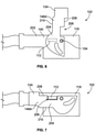
Figure 6 is a side view of thefirst connector 102 of the connector system 100 (shown inFigure 1 ) according to another embodiment. Thelever 134 is pivotally coupled to thehousing 118 at thepivot element 154 or post. Thelever 134 is in the open position relative to thehousing 118 inFigure 6 . Thebarcode label 112 is disposed on anouter surface 202 of thehousing 118, such that a wall of thehousing 118 defines the indicating feature in the illustrated embodiment. Thebarcode label 112 is concealed by asegment 204 of thelever 134, which defines the concealing feature that conceals thebarcode label 112 when thehousing 118 is not fully mated to the mating connector (such as thesecond connector 104 shown inFigure 3 ). Thebarcode label 112 is shown in phantom since it is concealed by thesegment 204 of thelever 134. In the illustrated embodiment, thebarcode label 112 is disposed on theouter surface 202 of theleft side wall 140 of thehousing 118, and thesegment 204 is thefirst arm 146A of thelever 134 that is disposed along theleft side wall 140. - The
arm 146A defines a recessedportion 206 along afirst edge 208 of thearm 146A. The recessedportion 206 is an indentation or cutout section in thearm 146A that extends from thefirst edge 208 towards, but not fully to, asecond edge 210 of thearm 146A. The recessedportion 206 is similar to thewindow 172 shown inFigure 3 , except that the recessedportion 206 is undefined along one side at thefirst edge 208. -
Figure 7 is a side view of thefirst connector 102 according to the embodiment shown inFigure 6 , showing thelever 134 in the closed position relative to thehousing 118. As shown inFigure 7 , when thelever 134 is pivoted to the closed position, the recessedportion 206 of thelever 134 aligns with thebarcode label 112 on thehousing 118 such that thebarcode label 112 is exposed and viewable through the recessedportion 206. Therefore, thebarcode label 112 is exposed relative to thefirst arm 146A, which formerly concealed thebarcode label 112. The recessedportion 206 has a size and shape that corresponds to the size and shape of thebarcode label 112 in order to expose the full area of thebarcode label 112. Although thebarcode label 112 is rectangular in the illustrated embodiment, thebarcode label 112 may be square-shaped, round, elliptical, or the like in other embodiments. - In alternative embodiments, the recessed
portion 206 may be defined along thesecond edge 210 of thearm 146A instead of along thefirst edge 208, or thearm 146A may define a window similar to thewindow 172 shown inFigure 3 instead of a recessed portion along one of theedges Figure 3 ) of thehousing 118 instead of, or in addition to, thefirst barcode label 112 shown inFigures 6 and 7 on theleft side wall 140, such that thesecond arm 146B (Figure 3 ) of thelever 134 conceals the second barcode label until thelever 134 is in the closed position. - In another alternative embodiment, the
barcode label 112 is disposed on an inner surface (not shown) of thelever 134, such that an arm of thelever 134 defines the indicating feature, instead of thebarcode label 112 being located on thehousing 118 as shown inFigures 6 and7. Thehousing 118 defines the concealing feature. For example, thebarcode label 112 may be disposed on a tab or portion of thelever 134 that aligns with and faces a side of thehousing 118 when thelever 134 is in the open position. When thelever 134 is pivoted to the closed position, however, the tab or portion of thelever 134 with thebarcode label 112 thereon projects beyond the side of the housing 118 (for example, vertically or laterally) to expose thebarcode label 112 for reading thebarcode label 112. -
Figure 8 is a perspective view of thefirst connector 102 of the connector system 100 (shown inFigure 1 ) according to another embodiment. Thehousing 118 of thefirst connector 102 optionally does not include a lever to provide a mating assist. In the illustrated embodiment, thebarcode label 112 is disposed on anouter surface 202 of thehousing 118. For example, thebarcode label 112 may be located on thefront end wall 144, such that thefront end wall 144 of thehousing 118 defines the indicating feature. Thehousing 118 further includes aCPA element 214 that is coupled to theouter surface 202. TheCPA element 214 extends over thebarcode label 112 to define the concealing feature that conceals thebarcode label 112 when thehousing 118 is not fully mated to the mating connector (for example, the second connector 104). In the illustrated embodiment, as themating interface 130 engages thesecond connector 104, theCPA element 214 is configured to engage thesecond connector 104 and to slide relative to thehousing 118 in arevealing direction 216 to expose thebarcode label 112 when thehousing 118 is fully mated to thesecond connector 104. Thus, theCPA element 214 provides position assurance because theCPA element 214 only slides relative to thehousing 118 when thehousing 118 is fully mated to thesecond connector 104. TheCPA element 214 is referred to below as aslidable insert 214. Therevealing direction 216 extends away from themating end 126 of thehousing 118 towards thetop wall 136. - In an embodiment, the
slidable insert 214 is a planar panel that is held in atrack 218 between tworails 220 of thehousing 118 that extend along theouter surface 202. Theslidable insert 214 is in a concealed position inFigure 8 , such that theslidable insert 214 extends over thebarcode label 112 to block thebarcode label 112 from being read by the sensor 114 (shown inFigure 2 ). Theslidable insert 214 includes at least onedeflectable latch 222 extending from afirst end 223 of theinsert 214. Thefirst end 223 of theinsert 214 is more proximate to themating end 126 of thehousing 118 than asecond end 225 of theinsert 214. Theinsert 214 includes twolatches 222 in the illustrated embodiment. Thelatches 222 each include acatch 224 that projects from therespective latch 222. Thecatch 224 is configured to engage a corresponding one of therails 220 of thehousing 118 to prohibit theslidable insert 214 from being moved in therevealing direction 216 along thetrack 218 when thehousing 118 is not fully mated to thesecond connector 104. - The
housing 124 of thesecond connector 104 in an embodiment includes at least onelug 226 that projects from acorresponding wall 228 of thehousing 124 that abuts or at least faces theslidable insert 214. In the illustrated embodiment, twolugs 226 are shown in phantom as thelugs 226 are located on an inner surface of thewall 228 that is not visible. -
Figure 9 illustrates the CPA element 214 (or slidable insert 214) and therails 220 of the first connector 102 (shown inFigure 8 ) as well as thelugs 226 of the second connector 104 (Figure 8 ) when thefirst connector 102 is fully mated to thesecond connector 104. As shown inFigure 9 , thelugs 226 have a tapered or angledupper edge 230 that forces and deflects thelatches 222 toward one another and away from the corresponding rails 220. The deflection of thelatches 222 releases thecatches 224 from engagement with abottom end 232 of therails 220. The relative movement of the first andsecond connectors lugs 226 vertically upward relative to therails 220. Thelugs 226 force theslidable insert 214 to move upwards along thetrack 218 with thelugs 226 in therevealing direction 216. Eventually, such movement of theslidable insert 214 exposes thebarcode label 112. Thebarcode label 112 in the illustrated embodiment is exposed below thefirst end 223 of theinsert 214, but in an alternative embodiment may be exposed through a window of theinsert 214. Thus, thebarcode label 112 is automatically exposed upon fully mating the first andsecond connectors connectors barcode label 112 is depicted as a two-dimensional matrix style barcode inFigure 9 . -
Figure 10 is a perspective view of a portion of thefirst connector 102 of the connector system 100 (shown inFigure 1 ) according to yet another embodiment. The portion of thefirst connector 102 that is shown includes thefront end wall 144. Like the embodiment shown inFigures 8 and 9 , thehousing 118 of thefirst connector 102 includes aCPA element 250 that is coupled to theouter surface 202 of thefront end wall 144 on or proximate to themating interface 130. TheCPA element 250 is referred to herein asslidable insert 250. In the illustrated embodiment, thebarcode label 112 is disposed on the slidable insert 250 (not on theouter surface 202 of the housing 118), such that theslidable insert 250 is the indicating feature. The concealing feature that conceals thebarcode label 112 when thefirst connector 102 is not fully mated to the mating connector is areceptacle 252 of thehousing 118. Theslidable insert 250 is held within thereceptacle 252. Thebarcode label 112 and portions of theslidable insert 250 within thereceptacle 252 are shown in phantom. - The
receptacle 252 has opposite left and right sides 254, 256 secured to theouter surface 202 of thehousing 118 and afirst opening 258 at a first orlower end 260 of thereceptacle 252. The left and right sides 254, 256 of thereceptacle 252 optionally may be defined by therails 220 shown inFigures 8 and 9 . Thelower end 260 of thereceptacle 252 is more proximate to themating end 126 of thehousing 118 than a second orupper end 262 of thereceptacle 252. Theslidable insert 250 may have a similar shape to theslidable insert 214 shown inFigures 8 and 9 . For example, theslidable insert 250 includes twolatches 264 that protrude through thefirst opening 258 at thelower end 260 of thereceptacle 252. Thelatches 264, like thelatches 222 shown inFigures 8 and 9 , are configured to prohibit movement of theslidable insert 250 from the concealed position to the exposed position until a fully mated connection is achieved. Lugs 226 (shown inFigure 8 ) of the second connector 104 (Figure 8 ) release thelatches 264 and drive theslidable insert 250 in therevealing direction 216 to the exposed position. - In the illustrated embodiment, the
receptacle 252 has asecond opening 266 at theupper end 262 of thereceptacle 252. Although not shown, when thereceptacle 252 is in the exposed position, atop end 268 of theslidable insert 250 protrudes through thesecond opening 266 and thebarcode label 112 on theinsert 250 is exposed above theupper end 262 of thereceptacle 252. In an alternative embodiment, thereceptacle 252 may define a window, and thebarcode label 112 is exposed through the window of thereceptacle 252 when theslidable insert 250 is in the exposed position. In such an alternative embodiment, theupper end 262 of thereceptacle 252 optionally may be closed (such that thereceptacle 252 does not define the second opening 266). -
Figure 11 is a perspective view of a portion of thefirst connector 102 of the connector system 100 (shown inFigure 1 ) formed in accordance with another embodiment. In the illustrated embodiment, thebarcode label 112 is disposed on aCPA element 270 which defines the indicating feature, like the embodiment shown inFigure 10 . TheCPA element 270, referred to herein asslidable insert 270, is coupled to and disposed along aninner surface 272 of thefront end wall 144 of thehousing 118. Thefront end wall 144 defines awindow 274 that extends through thewall 144 between theinner surface 272 and theouter surface 202 thereof. Thewall 144 defines the concealing feature that conceals thebarcode label 112 when theslidable insert 270 is in the concealed position. Theslidable insert 270 is in the concealed position relative to thehousing 118 inFigure 11 . Thebarcode label 112 and most of theslidable insert 270 are shown in phantom since these components are located on the other side of thefront end wall 144. Alternatively, another wall of thehousing 118 may be used as the concealing feature instead of thefront end wall 144. - The mechanism that releases the
slidable insert 270 from the concealed position and moves theslidable insert 270 in therevealing direction 216 to the exposed position optionally may be similar to the embodiments shown and described inFigures 8-10 . Thebarcode label 112 is disposed on an outward-facing surface of theslidable insert 270 such that when theslidable insert 270 is in the exposed position, thebarcode label 112 aligns with thewindow 274 and is viewable from outside thehousing 118 through thewindow 274. With additional reference toFigure 3 , the embodiment shown inFigure 11 may be used, for example, when thehousing 124 of thesecond connector 104 is received within an interior chamber of thehousing 118 of thefirst connector 102 during the mating operation, instead of thehousing 118 being received in theinterior chamber 132 of thehousing 124 as shown inFigure 3 . -
Figure 12 is a top perspective view of thefirst connector 102 according to another embodiment. Thefirst connector 102 includes aCPA element 280 that defines the concealing feature. TheCPA element 280 is held on thetop wall 136 of thehousing 118 and is slidable relative to thehousing 118. The barcode label 112 (shown inFigure 13 ) is disposed on theouter surface 202 of thetop wall 136, such that thetop wall 136 of thehousing 118 is the indicating feature. Thebarcode label 112 is concealed by theCPA element 280 in the illustrated position so thebarcode label 112 is not viewable or machine-readable. Thus, thetop wall 136 is in the concealed position relative to theCPA element 280 inFigure 12 . - The
first connector 102 includes thelever 134 that provides a mating assist for mating thefirst connector 102 with the second connector 104 (shown inFigure 3 ). Thelever 134 is shown in the closed position. In an embodiment, theCPA element 280 is restricted from moving relative to thehousing 118 when thelever 134 is not in the closed position. As thelever 134 is rotated to the closed position, afirst tab 282 that projects from thehandle 148 of thelever 134 engages adeflectable latch 284 of theCPA element 280, which releases thelatch 284 from acatch surface 286 of thehousing 118, allowing theCPA element 280 to slide in arevealing direction 288 relative to thehousing 118 and thelever 134 thereon. -
Figure 13 is a top perspective view of thefirst connector 102 shown inFigure 12 . InFigure 13 , thetop wall 136 of thehousing 118 is in the revealed position relative to theCPA element 280. For example, theCPA element 280 has been moved in therevealing direction 288 from the initial location shown inFigure 12 to the final location shown inFigure 13 to reveal thebarcode label 112 that is disposed on thetop wall 136. As theCPA element 280 moves in therevealing direction 288, aledge 290 ofCPA element 280 extends over a portion of thehandle 148 of thelever 134 to mechanically block thelever 134 from rotating from the closed position towards the open position. For example, in the illustrated embodiment theledge 290 extends over a second tab 292 (shown in more detail inFigure 12 ) that projects from thehandle 148. By extending over thehandle 148, theCPA element 280 provides a lock that holds thelever 134 in the closed position. Optionally, the deflectable latch 284 (or a different latch) of theCPA element 280 may be configured to engage asecond catch surface 294 of thehousing 118 when theCPA element 280 is in the position shown inFigure 13 to prohibit theCPA element 280 from inadvertently being moved relative to thehousing 118 in a concealingdirection 296 that is opposite therevealing direction 288. - It is to be understood that the above description is intended to be illustrative, and not restrictive. For example, the above-described embodiments (and/or aspects thereof) may be used in combination with each other. In addition, many modifications may be made to adapt a particular situation or material to the teachings of the invention without departing from its scope. Dimensions, types of materials, orientations of the various components, and the number and positions of the various components described herein are intended to define parameters of certain embodiments, and are by no means limiting and are merely exemplary embodiments. Many other embodiments and modifications within the spirit and scope of the claims will be apparent to those of skill in the art upon reviewing the above description. The scope of the invention should, therefore, be determined with reference to the appended claims, along with the full scope of equivalents to which such claims are entitled.
- According to one aspect of the invention there is provided an electrical connector having recordable position assurance, the electrical connector comprising: a housing having a mating interface configured to engage a complementary mating connector during a mating operation; at least one electrical conductor held in the housing; an indicating feature carried by the housing, the indicating feature having a visual identifier disposed thereon; and a concealing feature carried by the housing, wherein the indicating feature and the concealing feature are movable relative to each other between a concealed position and an exposed position, the concealing feature concealing at least a portion of the visual identifier in the concealed position, the visual identifier being at least one of exposed or exposable in the exposed position; wherein the indicating feature is in the concealed position relative to the concealing feature when the housing is not fully mated relative to the mating connector, and the indicating feature is in the exposed position relative to the concealing feature when the housing is fully mated to the mating connector.
- Preferably the visual identifier identifies the electrical connector, the visual identifier being machine-readable such that the visual identifier is able to be read by a sensor when the visual identifier is exposed in the exposed position of the indicating feature relative to the concealing feature.
- Preferably the visual identifier is one of a one-dimensional barcode, a two-dimensional barcode, or a three-dimensional barcode.
- Preferably the housing includes a lever that is movable relative to the housing between an open position and a closed position, the lever configured to engage the mating connector and move the housing and the mating connector relatively towards one another as the lever is moved from the open position to the closed position such that the housing is fully mated to the mating connector when the lever is in the closed position, the lever defining the concealing feature.
- Preferably a side wall of the housing defines the indicating feature, the visual identifier is disposed on an outer surface of the side wall, the side wall being pivotally coupled to an arm of the lever, the arm concealing the visual identifier when the lever is not in the closed position, the visual identifier being exposed at least one of through a window extending through the arm or outside of a perimeter of the arm when the lever is in the closed position.
- Preferably the indicating feature is a connector position assurance (CPA) element that the visual identifier is disposed thereon, the CPA element being coupled to the lever and movable relative to the lever, the visual identifier being concealed by a segment of the lever when the CPA element is in the concealed position relative to the lever, the visual identifier being exposable at least one of through a window defined in the segment or outside a perimeter of the segment when the CPA element is in the exposed position relative to the lever.
- Preferably the lever includes at least one tab that engages the CPA element to block movement of the CPA element from the concealed position to the exposed position relative to the lever when the lever is not in the closed position, the housing defining at least one protrusion that engages and deflects the at least one tab when the lever is in the closed position such that the CPA element is able to be moved to the exposed position relative to the lever.
- Preferably a wall of the housing defines the indicating feature, the visual identifier is disposed on an outer surface of the wall, the concealing feature being a connector position assurance (CPA) element that is coupled to and movable relative to the wall of the housing, the CPA element extending over and concealing the visual identifier when the CPA element is in the concealed position relative to the wall.
- Preferably the wall of the housing that defines the indicating feature is at least one of on or proximate to the mating interface, the CPA element being configured to engage the mating connector and to be moved by the mating connector in a revealing direction relative to the wall of the housing as the housing is being mated to the mating connector such that the CPA element is in the exposed position relative to the wall and the visual identifier is exposed when the housing is fully mated to the mating connector.
- Preferably the CPA element is held in a track between two rails on the wall of the housing, the CPA element including at least one deflectable latch extending from a first end of the CPA element, the at least one deflectable latch engaging at least one of the rails to restrict movement of the CPA element in the revealing direction to the exposed position when the housing is not fully mated to the mating connector, the at least one deflectable latch configured to be deflected by at least one corresponding lug of the mating connector as the housing is being mated to the mating connector to allow the CPA element to be moved relative to the rails to the exposed position.
Claims (9)
- An electrical connector (102) having recordable position assurance, the electrical connector (102) comprising:a housing (118) having a mating interface (130) configured to engage a complementary mating connector (104) during a mating operation;at least one electrical conductor (120) held in the housing (118);an indicating feature carried by the housing (118), the indicating feature having a visual identifier (112) disposed thereon; anda concealing feature carried by the housing (118), wherein the indicating feature and the concealing feature are movable relative to each other between a concealed position and an exposed position, the concealing feature concealing at least a portion of the visual identifier in the concealed position, the visual identifier being exposed in the exposed position;wherein the indicating feature is in the concealed position relative to the concealing feature when the housing (118) is not fully mated relative to the mating connector (104), and the indicating feature is in the exposed position relative to the concealing feature when the housing (118) is fully mated to the mating connector (104), the housing (118) includes a connector position assurance or CPA element (250) that is coupled to an outer surface (202) of a front end wall (144) on or proximate to the mating interface (130), the visual identifier (112) is disposed on the CPA element (250) such that the CPA element (250) is the indicating feature, the concealing feature that conceals the visual identifier (112) when the first connector (102) is not fully mated to the mating connector (104) is a receptacle (252) of the housing (118) and the CPA element (250) is held within the receptacle (252).
- The electrical connector (102) of claim 1, wherein the receptacle (252) has opposite left and right sides secured to the outer surface (202) of the housing (118) and a first opening (258) at a first or lower end (260) of the receptacle (252) which is more proximate to the mating end (126) of the housing (118) than a second or upper end (262) of the receptacle (252).
- The electrical connector (102) of claim 2, wherein the left and right sides of the receptacle (252) are defined by the rails.
- The electrical connector (102) of claim 2 or 3 wherein the CPA element (250) includes two latches (264) that protrude through the first opening (258) at the lower end (260) of the receptacle (252) that are configured to prohibit movement of the CPA element (250) from the concealed position to the exposed position until a fully mated connection is achieved.
- The electrical connector (102) of claim 2, 3 or 4 wherein the receptacle (252) has a second opening (266) at the upper end (262) of the receptacle (252) and when the receptacle (252) is in the exposed position, a top end (268) of the CPA element (250) protrudes through the second opening (266) and the visual identifier (112) on the CPA element (250) is exposed above the upper end (262) of the receptacle (252).
- The electrical connector (102) of claim 2, 3 or 4 wherein the receptacle (252) defines a window, and the visual identifier (112) is exposed through the window of the receptacle (252) when the CPA element (250) is in the exposed position.
- The electrical connector (102) of claim 6 wherein the upper end (262) of the receptacle (252) is closed.
- The electrical connector (102) of any preceding claim, wherein the visual identifier (112) identifies the electrical connector (102), the visual identifier (112) being machine-readable such that the visual identifier (112) is able to be read by a sensor (114) when the visual identifier (112) is exposed in the exposed position of the indicating feature relative to the concealing feature.
- The electrical connector (102) of any preceding claim, wherein the visual identifier (112) is one of a one-dimensional barcode, a two-dimensional barcode, or a three-dimensional barcode.
Applications Claiming Priority (3)
| Application Number | Priority Date | Filing Date | Title |
|---|---|---|---|
| US14/950,599 US9583860B1 (en) | 2015-11-24 | 2015-11-24 | Electrical connector with recordable position assurance |
| PCT/US2016/063058 WO2017091500A1 (en) | 2015-11-24 | 2016-11-21 | Electrical connector with recordable position assurance |
| EP16805706.5A EP3381091B1 (en) | 2015-11-24 | 2016-11-21 | Electrical connector with recordable position assurance |
Related Parent Applications (2)
| Application Number | Title | Priority Date | Filing Date |
|---|---|---|---|
| EP16805706.5A Division EP3381091B1 (en) | 2015-11-24 | 2016-11-21 | Electrical connector with recordable position assurance |
| EP16805706.5A Division-Into EP3381091B1 (en) | 2015-11-24 | 2016-11-21 | Electrical connector with recordable position assurance |
Publications (1)
| Publication Number | Publication Date |
|---|---|
| EP3958409A1 true EP3958409A1 (en) | 2022-02-23 |
Family
ID=57472118
Family Applications (2)
| Application Number | Title | Priority Date | Filing Date |
|---|---|---|---|
| EP16805706.5A Active EP3381091B1 (en) | 2015-11-24 | 2016-11-21 | Electrical connector with recordable position assurance |
| EP21202265.1A Pending EP3958409A1 (en) | 2015-11-24 | 2016-11-21 | Electrical connector with recordable position assurance |
Family Applications Before (1)
| Application Number | Title | Priority Date | Filing Date |
|---|---|---|---|
| EP16805706.5A Active EP3381091B1 (en) | 2015-11-24 | 2016-11-21 | Electrical connector with recordable position assurance |
Country Status (10)
| Country | Link |
|---|---|
| US (1) | US9583860B1 (en) |
| EP (2) | EP3381091B1 (en) |
| JP (3) | JP6602978B2 (en) |
| KR (3) | KR102109135B1 (en) |
| CN (3) | CN112086813B (en) |
| BR (1) | BR112018010194A8 (en) |
| CA (1) | CA3005758C (en) |
| DE (1) | DE202016008846U1 (en) |
| MX (1) | MX2018006284A (en) |
| WO (1) | WO2017091500A1 (en) |
Families Citing this family (43)
| Publication number | Priority date | Publication date | Assignee | Title |
|---|---|---|---|---|
| US9748695B2 (en) * | 2014-04-30 | 2017-08-29 | Ford Global Technologies, Llc | High voltage connector assembly |
| US9583860B1 (en) * | 2015-11-24 | 2017-02-28 | Te Connectivity Corporation | Electrical connector with recordable position assurance |
| US9748693B1 (en) * | 2016-02-10 | 2017-08-29 | Yazaki North America, Inc. | Connector position assurance with identification feature |
| US9905953B1 (en) | 2016-09-30 | 2018-02-27 | Slobodan Pavlovic | High power spring-actuated electrical connector |
| WO2019082453A1 (en) * | 2017-10-26 | 2019-05-02 | オリンパス株式会社 | Connector apparatus and endoscope apparatus provided with connector apparatus |
| BR112020009997B1 (en) * | 2017-11-28 | 2023-05-09 | Commscope Technologies Llc | INDICATION ELEMENT, INDICATION ELEMENT SYSTEM FOR TELECOMMUNICATION SYSTEM AND TELECOMMUNICATION SYSTEM |
| CN115832744A (en) | 2018-02-26 | 2023-03-21 | 伊顿智能动力有限公司 | Spring actuated electrical connector for high power applications |
| EP3776748A4 (en) * | 2018-03-29 | 2022-01-26 | CommScope Technologies LLC | Indicia and method for identifying telecommunications components |
| US10651586B2 (en) * | 2018-06-01 | 2020-05-12 | Tyco Electronics Brasil Ltda | Electrical connector with machine-readable graphic identifier |
| CN112956085B (en) | 2018-06-07 | 2023-09-15 | 皇家精密制品有限责任公司 | Electrical connector system with internal spring components and use thereof |
| CN109119819B (en) * | 2018-08-25 | 2024-04-19 | 广州知崇新能源科技有限公司 | Metal elbow high-voltage connector |
| USD916044S1 (en) | 2018-10-19 | 2021-04-13 | Commscope Technologies Llc | Telecommunications enclosure |
| DE102018009478A1 (en) * | 2018-12-04 | 2020-06-04 | Kostal Kontakt Systeme Gmbh | Connector arrangement |
| CN113508498A (en) | 2019-01-21 | 2021-10-15 | 皇家精密制品有限责任公司 | Power distribution assembly with boltless bus bar system |
| JP7092712B2 (en) * | 2019-07-11 | 2022-06-28 | 矢崎総業株式会社 | Lever type connector |
| AT522804B1 (en) * | 2019-09-03 | 2021-02-15 | Henn Gmbh & Co Kg | Connectors for connecting lines for liquid or gaseous media |
| US11721942B2 (en) | 2019-09-09 | 2023-08-08 | Eaton Intelligent Power Limited | Connector system for a component in a power management system in a motor vehicle |
| WO2021050499A1 (en) * | 2019-09-09 | 2021-03-18 | Royal Precision Products Llc | Connector recording system with readable and recordable indicia |
| DE102019126467B4 (en) * | 2019-10-01 | 2022-03-31 | Lisa Dräxlmaier GmbH | CONNECTOR FOR MODULAR INSERTION ARRANGEMENT, PLUG ARRANGEMENT, USE AND METHOD OF CONNECTOR MANUFACTURE |
| US11296462B2 (en) * | 2019-10-10 | 2022-04-05 | Aptiv Technologies Limited | Connector assembly with a connector position assurance indicator |
| DE102019219453A1 (en) * | 2019-12-12 | 2021-06-17 | Lear Corporation | Process for manufacturing electrical connectors |
| US10855032B1 (en) * | 2019-12-30 | 2020-12-01 | GM Global Technology Operations LLC | Electrical connector |
| EP3886267A1 (en) * | 2020-03-27 | 2021-09-29 | Yamaichi Electronics Deutschland GmbH | Connector assembly, connector system and method |
| US11698157B2 (en) | 2020-07-24 | 2023-07-11 | Cooper-Standard Automotive Inc. | Quick connector latch verification utilizing a scannable code |
| JP2023536817A (en) | 2020-07-29 | 2023-08-30 | イートン インテリジェント パワー リミテッド | Electrical connector system with cylindrical terminal body |
| US11837822B2 (en) * | 2020-09-22 | 2023-12-05 | Aptiv Technologies Limited | Connector assembly with a connector position assurance indicator |
| US11558972B2 (en) * | 2020-11-19 | 2023-01-17 | Aptiv Technologies Limited | Electrical center cover with machine-readable indicator confirmation of lock engagement |
| KR20230132576A (en) | 2021-01-23 | 2023-09-15 | 코스탈 콘탁트 치스테메 게엠베하 | electrical plug connector |
| DE102021005000A1 (en) | 2021-01-23 | 2022-07-28 | Kostal Kontakt Systeme Gmbh | Electrical connector |
| JP2022147207A (en) * | 2021-03-23 | 2022-10-06 | 住友電装株式会社 | lever type connector |
| JP2022147206A (en) * | 2021-03-23 | 2022-10-06 | 住友電装株式会社 | lever type connector |
| DE102021108320A1 (en) | 2021-04-01 | 2022-10-06 | Bayerische Motoren Werke Aktiengesellschaft | Connector for a high-voltage vehicle electrical system of a motor vehicle with an optical display, high-voltage vehicle electrical system and motor vehicle |
| US20230058780A1 (en) * | 2021-08-23 | 2023-02-23 | J.S.T. Corporation | Verification system or verification method for detecting a connector position assurance (cpa) device's closure relative to a housing using a machine or electric/electronic scan system for reading or detecting surface scan of a predetermined barcode or qr code, and portions thereof |
| US20230054816A1 (en) * | 2021-08-23 | 2023-02-23 | J.S.T. Corporation | Verification system or verification method for detecting a connector position assurance (cpa) device's closure relative to a housing using a machine or electric/electronic scan system for reading or detecting surface scan of a predetermined word or character, and portions thereof |
| DE102021005004A1 (en) | 2021-10-06 | 2023-04-06 | Kostal Kontakt Systeme Gmbh | Electrical connector |
| JP2023069707A (en) * | 2021-11-08 | 2023-05-18 | 株式会社オートネットワーク技術研究所 | lever type connector |
| US11849561B2 (en) | 2021-12-22 | 2023-12-19 | In Vue Security Products Inc. | Data center security systems and devices |
| WO2023122159A2 (en) * | 2021-12-22 | 2023-06-29 | Invue Security Products Inc. | Data center security systems and devices |
| JP2023102487A (en) * | 2022-01-12 | 2023-07-25 | 株式会社オートネットワーク技術研究所 | connector structure |
| DE102023102897A1 (en) | 2022-02-09 | 2023-08-10 | Hirschmann Automotive Gmbh | Connector with a two-piece identifier |
| KR102664639B1 (en) * | 2022-06-23 | 2024-05-10 | 주식회사 경신 | High voltage connector |
| WO2024030158A1 (en) | 2022-08-04 | 2024-02-08 | J.S.T. Corporation | A hidden releasable barcode or qr code for indicating mating or non-mating of two elements, and operation thereof |
| DE102022002888A1 (en) | 2022-08-10 | 2024-02-15 | Kostal Kontakt Systeme Gmbh | Connector arrangement |
Citations (2)
| Publication number | Priority date | Publication date | Assignee | Title |
|---|---|---|---|---|
| US5120255A (en) * | 1990-03-01 | 1992-06-09 | Yazaki Corporation | Complete locking confirming device for confirming the complete locking of an electric connector |
| US20150318640A1 (en) * | 2014-04-30 | 2015-11-05 | Ford Global Technologies, Llc | High Voltage Connector Assembly |
Family Cites Families (23)
| Publication number | Priority date | Publication date | Assignee | Title |
|---|---|---|---|---|
| JPH0622941Y2 (en) * | 1986-06-09 | 1994-06-15 | 関東自動車工業株式会社 | connector |
| JPH07114135B2 (en) * | 1990-03-28 | 1995-12-06 | 矢崎総業株式会社 | Lock detection mechanism for electrical connectors |
| US5376017A (en) * | 1992-09-29 | 1994-12-27 | Sumitomo Wiring Systems, Ltd. | Connector |
| JP3603760B2 (en) * | 2000-08-11 | 2004-12-22 | 住友電装株式会社 | Lever type connector |
| US7134200B2 (en) * | 2000-11-01 | 2006-11-14 | International Business Machines Corporation | Device and method for identifying cables |
| JP3644408B2 (en) * | 2001-05-30 | 2005-04-27 | 住友電装株式会社 | connector |
| DE20214434U1 (en) * | 2002-09-17 | 2002-12-05 | Kostal Leopold Gmbh & Co Kg | Arrangement for identifying an assembly formed from at least two parts |
| JP3960252B2 (en) * | 2003-04-15 | 2007-08-15 | 住友電装株式会社 | Lever type connector |
| DE20311182U1 (en) * | 2003-07-21 | 2004-02-19 | Tyco Electronics Amp Gmbh | In line electrical connector for cables has plug produced with projections that latch onto bush and ensure core orientation. |
| WO2006095607A1 (en) * | 2005-03-10 | 2006-09-14 | Honda Motor Co., Ltd. | Connector for providing waterproof connection and its connection state examining method |
| US7223130B2 (en) * | 2005-05-17 | 2007-05-29 | J.S.T. Corporation | Electrical connector |
| US7351089B2 (en) * | 2006-04-28 | 2008-04-01 | Delphi Technologies, Inc. | Electrical connector having a CPA plug |
| US7329132B1 (en) * | 2006-07-31 | 2008-02-12 | Yazaki North America, Inc. | Low-insertion force-lever connector for blind mating |
| DE102007008042A1 (en) * | 2007-02-17 | 2008-08-21 | Escha Bauelemente Gmbh | Plug with indicator ring |
| US7381084B1 (en) * | 2007-04-17 | 2008-06-03 | Chrysler Llc | Connector position assurance arrangement |
| US7497723B2 (en) * | 2007-06-14 | 2009-03-03 | Nordson Corporation | High-voltage electrical connector with visual indicator |
| US7931490B2 (en) * | 2007-10-19 | 2011-04-26 | Lockheed Martin Corporation | Indicating the integrity of a connector seal |
| JP5231381B2 (en) * | 2009-11-17 | 2013-07-10 | 株式会社東海理化電機製作所 | Connector lock structure for battery charging power receiving connector |
| FR2962857B1 (en) * | 2010-07-16 | 2016-09-09 | Tyco Electronics France Sas | CONNECTOR WITH CPA DEVICE ON LOCKING ELEMENT |
| US9111466B2 (en) * | 2013-01-17 | 2015-08-18 | Mellanoy Technologies Ltd. | Efficient access to connectivity information using cable identification |
| US8944844B2 (en) | 2013-01-18 | 2015-02-03 | Tyco Electronics Corporation | Connector mating assurance |
| US9059542B2 (en) * | 2013-07-23 | 2015-06-16 | Tyco Electronics Corporation | Quick connect power connector |
| US9583860B1 (en) | 2015-11-24 | 2017-02-28 | Te Connectivity Corporation | Electrical connector with recordable position assurance |
-
2015
- 2015-11-24 US US14/950,599 patent/US9583860B1/en active Active
-
2016
- 2016-11-21 CA CA3005758A patent/CA3005758C/en active Active
- 2016-11-21 CN CN202010829822.6A patent/CN112086813B/en active Active
- 2016-11-21 KR KR1020197033337A patent/KR102109135B1/en active IP Right Grant
- 2016-11-21 EP EP16805706.5A patent/EP3381091B1/en active Active
- 2016-11-21 KR KR1020187017758A patent/KR102045514B1/en active IP Right Grant
- 2016-11-21 KR KR1020207012851A patent/KR102190646B1/en active IP Right Grant
- 2016-11-21 EP EP21202265.1A patent/EP3958409A1/en active Pending
- 2016-11-21 JP JP2018526513A patent/JP6602978B2/en active Active
- 2016-11-21 MX MX2018006284A patent/MX2018006284A/en unknown
- 2016-11-21 CN CN201680068196.5A patent/CN108292818B/en active Active
- 2016-11-21 WO PCT/US2016/063058 patent/WO2017091500A1/en active Application Filing
- 2016-11-21 DE DE202016008846.8U patent/DE202016008846U1/en active Active
- 2016-11-21 CN CN202210954352.5A patent/CN115473079A/en active Pending
- 2016-11-21 BR BR112018010194A patent/BR112018010194A8/en not_active IP Right Cessation
-
2019
- 2019-10-09 JP JP2019185859A patent/JP6921155B2/en active Active
-
2021
- 2021-07-26 JP JP2021121278A patent/JP7301913B2/en active Active
Patent Citations (2)
| Publication number | Priority date | Publication date | Assignee | Title |
|---|---|---|---|---|
| US5120255A (en) * | 1990-03-01 | 1992-06-09 | Yazaki Corporation | Complete locking confirming device for confirming the complete locking of an electric connector |
| US20150318640A1 (en) * | 2014-04-30 | 2015-11-05 | Ford Global Technologies, Llc | High Voltage Connector Assembly |
Also Published As
| Publication number | Publication date |
|---|---|
| JP2018535524A (en) | 2018-11-29 |
| BR112018010194A8 (en) | 2019-02-26 |
| CA3005758C (en) | 2020-06-16 |
| US9583860B1 (en) | 2017-02-28 |
| JP6921155B2 (en) | 2021-08-18 |
| JP6602978B2 (en) | 2019-11-06 |
| CA3005758A1 (en) | 2017-06-01 |
| JP2021177495A (en) | 2021-11-11 |
| CN112086813A (en) | 2020-12-15 |
| CN112086813B (en) | 2022-11-15 |
| BR112018010194A2 (en) | 2018-11-21 |
| CN115473079A (en) | 2022-12-13 |
| JP2020027801A (en) | 2020-02-20 |
| MX2018006284A (en) | 2018-09-07 |
| EP3381091B1 (en) | 2021-11-24 |
| KR20200051846A (en) | 2020-05-13 |
| CN108292818A (en) | 2018-07-17 |
| DE202016008846U1 (en) | 2020-01-31 |
| KR102190646B1 (en) | 2020-12-15 |
| KR20180084992A (en) | 2018-07-25 |
| KR20190128755A (en) | 2019-11-18 |
| KR102109135B1 (en) | 2020-05-12 |
| EP3381091A1 (en) | 2018-10-03 |
| JP7301913B2 (en) | 2023-07-03 |
| CN108292818B (en) | 2020-09-11 |
| KR102045514B1 (en) | 2019-11-18 |
| WO2017091500A1 (en) | 2017-06-01 |
Similar Documents
| Publication | Publication Date | Title |
|---|---|---|
| CA3005758C (en) | Electrical connector with recordable position assurance | |
| US10651586B2 (en) | Electrical connector with machine-readable graphic identifier | |
| EP1072178B1 (en) | Circuit card insertion and removal system | |
| US8169783B2 (en) | Latch assembly for a pluggable electronic module | |
| US5021003A (en) | Apparatus for confirming fitting of electric connector | |
| EP1983618B1 (en) | A connector | |
| US6773279B2 (en) | Lever-type connector, a lever-type connector assembly and a method of assembling a lever-type connector with a mating connector | |
| EP2075880A1 (en) | Lever-type connector, connector assembly and connecting method | |
| US8613630B2 (en) | Latch assembly for a pluggable electronic module | |
| US9843140B1 (en) | Electrical connector having expandable backshell | |
| WO2003021724A1 (en) | Cable connector with slide-actuated engagement means | |
| JP3867650B2 (en) | Package with locking mechanism | |
| US5513079A (en) | Mass termination of signals from electronic systems to devices under test | |
| JP2005310492A (en) | Connector | |
| CN118120119A (en) | Rod type connector | |
| CN107832186A (en) | Diagnosis unit, hard disk module and server | |
| JP2007234475A (en) | Lever type connector |
Legal Events
| Date | Code | Title | Description |
|---|---|---|---|
| PUAI | Public reference made under article 153(3) epc to a published international application that has entered the european phase |
Free format text: ORIGINAL CODE: 0009012 |
|
| STAA | Information on the status of an ep patent application or granted ep patent |
Free format text: STATUS: THE APPLICATION HAS BEEN PUBLISHED |
|
| AC | Divisional application: reference to earlier application |
Ref document number: 3381091 Country of ref document: EP Kind code of ref document: P |
|
| AK | Designated contracting states |
Kind code of ref document: A1 Designated state(s): AL AT BE BG CH CY CZ DE DK EE ES FI FR GB GR HR HU IE IS IT LI LT LU LV MC MK MT NL NO PL PT RO RS SE SI SK SM TR |
|
| STAA | Information on the status of an ep patent application or granted ep patent |
Free format text: STATUS: REQUEST FOR EXAMINATION WAS MADE |
|
| 17P | Request for examination filed |
Effective date: 20220815 |
|
| RBV | Designated contracting states (corrected) |
Designated state(s): AL AT BE BG CH CY CZ DE DK EE ES FI FR GB GR HR HU IE IS IT LI LT LU LV MC MK MT NL NO PL PT RO RS SE SI SK SM TR |
|
| RAP1 | Party data changed (applicant data changed or rights of an application transferred) |
Owner name: TE CONNECTIVITY SOLUTIONS GMBH |
|
| REG | Reference to a national code |
Ref country code: DE Ref legal event code: R079 Free format text: PREVIOUS MAIN CLASS: H01R0013641000 Ipc: H01R0013460000 |
|
| GRAP | Despatch of communication of intention to grant a patent |
Free format text: ORIGINAL CODE: EPIDOSNIGR1 |
|
| STAA | Information on the status of an ep patent application or granted ep patent |
Free format text: STATUS: GRANT OF PATENT IS INTENDED |
|
| RIC1 | Information provided on ipc code assigned before grant |
Ipc: H01R 13/641 20060101ALI20240123BHEP Ipc: H01R 13/46 20060101AFI20240123BHEP |
|
| INTG | Intention to grant announced |
Effective date: 20240222 |