EP3958355A1 - Dispositif de fabrication d'électrode négative et procédé de fabrication d'électrode négative - Google Patents
Dispositif de fabrication d'électrode négative et procédé de fabrication d'électrode négative Download PDFInfo
- Publication number
- EP3958355A1 EP3958355A1 EP20809469.8A EP20809469A EP3958355A1 EP 3958355 A1 EP3958355 A1 EP 3958355A1 EP 20809469 A EP20809469 A EP 20809469A EP 3958355 A1 EP3958355 A1 EP 3958355A1
- Authority
- EP
- European Patent Office
- Prior art keywords
- negative electrode
- lithiation
- electrode structure
- roll
- section
- Prior art date
- Legal status (The legal status is an assumption and is not a legal conclusion. Google has not performed a legal analysis and makes no representation as to the accuracy of the status listed.)
- Pending
Links
- 238000004519 manufacturing process Methods 0.000 title description 16
- 238000006138 lithiation reaction Methods 0.000 claims abstract description 263
- 230000032683 aging Effects 0.000 claims abstract description 42
- 238000005470 impregnation Methods 0.000 claims abstract description 38
- 239000000615 nonconductor Substances 0.000 claims abstract description 25
- 238000005096 rolling process Methods 0.000 claims abstract description 20
- 238000005406 washing Methods 0.000 claims description 80
- 238000000034 method Methods 0.000 claims description 52
- 238000001035 drying Methods 0.000 claims description 45
- 229910052744 lithium Inorganic materials 0.000 claims description 45
- 239000003960 organic solvent Substances 0.000 claims description 39
- -1 polytetrafluoroethylene Polymers 0.000 claims description 22
- 238000004804 winding Methods 0.000 claims description 22
- 229910001220 stainless steel Inorganic materials 0.000 claims description 15
- 239000010935 stainless steel Substances 0.000 claims description 15
- 238000007600 charging Methods 0.000 claims description 12
- 239000004696 Poly ether ether ketone Substances 0.000 claims description 11
- 229920002530 polyetherether ketone Polymers 0.000 claims description 11
- XEEYBQQBJWHFJM-UHFFFAOYSA-N Iron Chemical compound [Fe] XEEYBQQBJWHFJM-UHFFFAOYSA-N 0.000 claims description 10
- XAGFODPZIPBFFR-UHFFFAOYSA-N aluminium Chemical compound [Al] XAGFODPZIPBFFR-UHFFFAOYSA-N 0.000 claims description 10
- RYGMFSIKBFXOCR-UHFFFAOYSA-N Copper Chemical compound [Cu] RYGMFSIKBFXOCR-UHFFFAOYSA-N 0.000 claims description 9
- 239000004743 Polypropylene Substances 0.000 claims description 9
- 229910052782 aluminium Inorganic materials 0.000 claims description 9
- 229910052802 copper Inorganic materials 0.000 claims description 9
- 239000010949 copper Substances 0.000 claims description 9
- 229920001155 polypropylene Polymers 0.000 claims description 9
- 229920001343 polytetrafluoroethylene Polymers 0.000 claims description 8
- 239000004810 polytetrafluoroethylene Substances 0.000 claims description 8
- 239000010936 titanium Substances 0.000 claims description 6
- 239000011575 calcium Substances 0.000 claims description 5
- 150000001875 compounds Chemical class 0.000 claims description 5
- 229910052742 iron Inorganic materials 0.000 claims description 5
- 239000004698 Polyethylene Substances 0.000 claims description 4
- RTAQQCXQSZGOHL-UHFFFAOYSA-N Titanium Chemical compound [Ti] RTAQQCXQSZGOHL-UHFFFAOYSA-N 0.000 claims description 4
- 239000000919 ceramic Substances 0.000 claims description 4
- 229920001940 conductive polymer Polymers 0.000 claims description 4
- 239000011777 magnesium Substances 0.000 claims description 4
- 229910052751 metal Inorganic materials 0.000 claims description 4
- 239000002184 metal Substances 0.000 claims description 4
- 229910044991 metal oxide Inorganic materials 0.000 claims description 4
- 150000004706 metal oxides Chemical class 0.000 claims description 4
- 229920000573 polyethylene Polymers 0.000 claims description 4
- 229910052719 titanium Inorganic materials 0.000 claims description 4
- XUIMIQQOPSSXEZ-UHFFFAOYSA-N Silicon Chemical compound [Si] XUIMIQQOPSSXEZ-UHFFFAOYSA-N 0.000 claims description 3
- 229910052791 calcium Inorganic materials 0.000 claims description 3
- 229920000915 polyvinyl chloride Polymers 0.000 claims description 3
- 239000004800 polyvinyl chloride Substances 0.000 claims description 3
- 229910052710 silicon Inorganic materials 0.000 claims description 3
- 239000010703 silicon Substances 0.000 claims description 3
- OYPRJOBELJOOCE-UHFFFAOYSA-N Calcium Chemical compound [Ca] OYPRJOBELJOOCE-UHFFFAOYSA-N 0.000 claims description 2
- 229910052684 Cerium Inorganic materials 0.000 claims description 2
- FYYHWMGAXLPEAU-UHFFFAOYSA-N Magnesium Chemical compound [Mg] FYYHWMGAXLPEAU-UHFFFAOYSA-N 0.000 claims description 2
- GWXLDORMOJMVQZ-UHFFFAOYSA-N cerium Chemical compound [Ce] GWXLDORMOJMVQZ-UHFFFAOYSA-N 0.000 claims description 2
- 229910052749 magnesium Inorganic materials 0.000 claims description 2
- VSZWPYCFIRKVQL-UHFFFAOYSA-N selanylidenegallium;selenium Chemical compound [Se].[Se]=[Ga].[Se]=[Ga] VSZWPYCFIRKVQL-UHFFFAOYSA-N 0.000 claims description 2
- 229910052727 yttrium Inorganic materials 0.000 claims description 2
- VWQVUPCCIRVNHF-UHFFFAOYSA-N yttrium atom Chemical compound [Y] VWQVUPCCIRVNHF-UHFFFAOYSA-N 0.000 claims description 2
- 239000000243 solution Substances 0.000 description 48
- 239000007773 negative electrode material Substances 0.000 description 42
- WHXSMMKQMYFTQS-UHFFFAOYSA-N Lithium Chemical compound [Li] WHXSMMKQMYFTQS-UHFFFAOYSA-N 0.000 description 22
- 238000010325 electrochemical charging Methods 0.000 description 20
- 230000000052 comparative effect Effects 0.000 description 17
- 229910001416 lithium ion Inorganic materials 0.000 description 15
- 230000008569 process Effects 0.000 description 15
- OKTJSMMVPCPJKN-UHFFFAOYSA-N Carbon Chemical compound [C] OKTJSMMVPCPJKN-UHFFFAOYSA-N 0.000 description 14
- HBBGRARXTFLTSG-UHFFFAOYSA-N Lithium ion Chemical compound [Li+] HBBGRARXTFLTSG-UHFFFAOYSA-N 0.000 description 13
- 229910003002 lithium salt Inorganic materials 0.000 description 13
- 159000000002 lithium salts Chemical class 0.000 description 13
- 239000004020 conductor Substances 0.000 description 12
- JBTWLSYIZRCDFO-UHFFFAOYSA-N ethyl methyl carbonate Chemical compound CCOC(=O)OC JBTWLSYIZRCDFO-UHFFFAOYSA-N 0.000 description 12
- KMTRUDSVKNLOMY-UHFFFAOYSA-N Ethylene carbonate Chemical compound O=C1OCCO1 KMTRUDSVKNLOMY-UHFFFAOYSA-N 0.000 description 10
- 239000003792 electrolyte Substances 0.000 description 10
- 239000002245 particle Substances 0.000 description 9
- SBLRHMKNNHXPHG-UHFFFAOYSA-N 4-fluoro-1,3-dioxolan-2-one Chemical compound FC1COC(=O)O1 SBLRHMKNNHXPHG-UHFFFAOYSA-N 0.000 description 8
- MCMNRKCIXSYSNV-UHFFFAOYSA-N Zirconium dioxide Chemical compound O=[Zr]=O MCMNRKCIXSYSNV-UHFFFAOYSA-N 0.000 description 8
- 238000002161 passivation Methods 0.000 description 8
- VYPSYNLAJGMNEJ-UHFFFAOYSA-N Silicium dioxide Chemical compound O=[Si]=O VYPSYNLAJGMNEJ-UHFFFAOYSA-N 0.000 description 7
- 239000011230 binding agent Substances 0.000 description 7
- 239000002388 carbon-based active material Substances 0.000 description 7
- 238000010586 diagram Methods 0.000 description 7
- 238000009413 insulation Methods 0.000 description 7
- 239000002409 silicon-based active material Substances 0.000 description 7
- 230000006872 improvement Effects 0.000 description 6
- 238000009830 intercalation Methods 0.000 description 6
- 230000014759 maintenance of location Effects 0.000 description 6
- 229910001290 LiPF6 Inorganic materials 0.000 description 5
- PXHVJJICTQNCMI-UHFFFAOYSA-N Nickel Chemical compound [Ni] PXHVJJICTQNCMI-UHFFFAOYSA-N 0.000 description 5
- GWEVSGVZZGPLCZ-UHFFFAOYSA-N Titan oxide Chemical compound O=[Ti]=O GWEVSGVZZGPLCZ-UHFFFAOYSA-N 0.000 description 5
- 239000000654 additive Substances 0.000 description 5
- 230000000996 additive effect Effects 0.000 description 5
- 238000007599 discharging Methods 0.000 description 5
- 238000010294 electrolyte impregnation Methods 0.000 description 5
- 230000002687 intercalation Effects 0.000 description 5
- 229920001296 polysiloxane Polymers 0.000 description 5
- 239000002033 PVDF binder Substances 0.000 description 4
- 229910052799 carbon Inorganic materials 0.000 description 4
- IEJIGPNLZYLLBP-UHFFFAOYSA-N dimethyl carbonate Chemical compound COC(=O)OC IEJIGPNLZYLLBP-UHFFFAOYSA-N 0.000 description 4
- 239000011267 electrode slurry Substances 0.000 description 4
- 238000011156 evaluation Methods 0.000 description 4
- 239000012535 impurity Substances 0.000 description 4
- 239000011261 inert gas Substances 0.000 description 4
- 239000000463 material Substances 0.000 description 4
- 229910021382 natural graphite Inorganic materials 0.000 description 4
- 229920002981 polyvinylidene fluoride Polymers 0.000 description 4
- UHOVQNZJYSORNB-UHFFFAOYSA-N Benzene Chemical compound C1=CC=CC=C1 UHOVQNZJYSORNB-UHFFFAOYSA-N 0.000 description 3
- XEKOWRVHYACXOJ-UHFFFAOYSA-N Ethyl acetate Chemical compound CCOC(C)=O XEKOWRVHYACXOJ-UHFFFAOYSA-N 0.000 description 3
- KFZMGEQAYNKOFK-UHFFFAOYSA-N Isopropanol Chemical compound CC(C)O KFZMGEQAYNKOFK-UHFFFAOYSA-N 0.000 description 3
- ZMXDDKWLCZADIW-UHFFFAOYSA-N N,N-Dimethylformamide Chemical compound CN(C)C=O ZMXDDKWLCZADIW-UHFFFAOYSA-N 0.000 description 3
- 229910021383 artificial graphite Inorganic materials 0.000 description 3
- 230000008859 change Effects 0.000 description 3
- 238000006243 chemical reaction Methods 0.000 description 3
- 229910052681 coesite Inorganic materials 0.000 description 3
- 229910052906 cristobalite Inorganic materials 0.000 description 3
- 238000010292 electrical insulation Methods 0.000 description 3
- 238000010326 electrochemical discharging Methods 0.000 description 3
- 238000005755 formation reaction Methods 0.000 description 3
- 230000002427 irreversible effect Effects 0.000 description 3
- 239000007774 positive electrode material Substances 0.000 description 3
- 238000007086 side reaction Methods 0.000 description 3
- 239000000377 silicon dioxide Substances 0.000 description 3
- 229910052682 stishovite Inorganic materials 0.000 description 3
- 229910052905 tridymite Inorganic materials 0.000 description 3
- VAYTZRYEBVHVLE-UHFFFAOYSA-N 1,3-dioxol-2-one Chemical compound O=C1OC=CO1 VAYTZRYEBVHVLE-UHFFFAOYSA-N 0.000 description 2
- WNXJIVFYUVYPPR-UHFFFAOYSA-N 1,3-dioxolane Chemical compound C1COCO1 WNXJIVFYUVYPPR-UHFFFAOYSA-N 0.000 description 2
- YEJRWHAVMIAJKC-UHFFFAOYSA-N 4-Butyrolactone Chemical compound O=C1CCCO1 YEJRWHAVMIAJKC-UHFFFAOYSA-N 0.000 description 2
- 229920002134 Carboxymethyl cellulose Polymers 0.000 description 2
- OIFBSDVPJOWBCH-UHFFFAOYSA-N Diethyl carbonate Chemical compound CCOC(=O)OCC OIFBSDVPJOWBCH-UHFFFAOYSA-N 0.000 description 2
- RTZKZFJDLAIYFH-UHFFFAOYSA-N Diethyl ether Chemical compound CCOCC RTZKZFJDLAIYFH-UHFFFAOYSA-N 0.000 description 2
- 229920002943 EPDM rubber Polymers 0.000 description 2
- LFQSCWFLJHTTHZ-UHFFFAOYSA-N Ethanol Chemical compound CCO LFQSCWFLJHTTHZ-UHFFFAOYSA-N 0.000 description 2
- YCKRFDGAMUMZLT-UHFFFAOYSA-N Fluorine atom Chemical compound [F] YCKRFDGAMUMZLT-UHFFFAOYSA-N 0.000 description 2
- 229920000459 Nitrile rubber Polymers 0.000 description 2
- WYURNTSHIVDZCO-UHFFFAOYSA-N Tetrahydrofuran Chemical compound C1CCOC1 WYURNTSHIVDZCO-UHFFFAOYSA-N 0.000 description 2
- XLOMVQKBTHCTTD-UHFFFAOYSA-N Zinc monoxide Chemical compound [Zn]=O XLOMVQKBTHCTTD-UHFFFAOYSA-N 0.000 description 2
- 239000006230 acetylene black Substances 0.000 description 2
- 239000011149 active material Substances 0.000 description 2
- PNEYBMLMFCGWSK-UHFFFAOYSA-N aluminium oxide Inorganic materials [O-2].[O-2].[O-2].[Al+3].[Al+3] PNEYBMLMFCGWSK-UHFFFAOYSA-N 0.000 description 2
- 230000015572 biosynthetic process Effects 0.000 description 2
- 239000003660 carbonate based solvent Substances 0.000 description 2
- 229910052593 corundum Inorganic materials 0.000 description 2
- JHIVVAPYMSGYDF-UHFFFAOYSA-N cyclohexanone Chemical compound O=C1CCCCC1 JHIVVAPYMSGYDF-UHFFFAOYSA-N 0.000 description 2
- 229920001971 elastomer Polymers 0.000 description 2
- 239000008151 electrolyte solution Substances 0.000 description 2
- 239000000835 fiber Substances 0.000 description 2
- 239000011737 fluorine Substances 0.000 description 2
- 229910052731 fluorine Inorganic materials 0.000 description 2
- 239000003273 ketjen black Substances 0.000 description 2
- 238000007561 laser diffraction method Methods 0.000 description 2
- KWGKDLIKAYFUFQ-UHFFFAOYSA-M lithium chloride Chemical compound [Li+].[Cl-] KWGKDLIKAYFUFQ-UHFFFAOYSA-M 0.000 description 2
- VDVLPSWVDYJFRW-UHFFFAOYSA-N lithium;bis(fluorosulfonyl)azanide Chemical compound [Li+].FS(=O)(=O)[N-]S(F)(=O)=O VDVLPSWVDYJFRW-UHFFFAOYSA-N 0.000 description 2
- 229910052759 nickel Inorganic materials 0.000 description 2
- 239000000843 powder Substances 0.000 description 2
- RUOJZAUFBMNUDX-UHFFFAOYSA-N propylene carbonate Chemical compound CC1COC(=O)O1 RUOJZAUFBMNUDX-UHFFFAOYSA-N 0.000 description 2
- 239000005060 rubber Substances 0.000 description 2
- 230000000087 stabilizing effect Effects 0.000 description 2
- 229920003048 styrene butadiene rubber Polymers 0.000 description 2
- 239000000126 substance Substances 0.000 description 2
- 229910001845 yogo sapphire Inorganic materials 0.000 description 2
- DURPTKYDGMDSBL-UHFFFAOYSA-N 1-butoxybutane Chemical compound CCCCOCCCC DURPTKYDGMDSBL-UHFFFAOYSA-N 0.000 description 1
- VTHRQKSLPFJQHN-UHFFFAOYSA-N 3-[2-(2-cyanoethoxy)ethoxy]propanenitrile Chemical compound N#CCCOCCOCCC#N VTHRQKSLPFJQHN-UHFFFAOYSA-N 0.000 description 1
- 229920000049 Carbon (fiber) Polymers 0.000 description 1
- 229910000925 Cd alloy Inorganic materials 0.000 description 1
- 229920002153 Hydroxypropyl cellulose Polymers 0.000 description 1
- 229910010088 LiAlO4 Inorganic materials 0.000 description 1
- 229910001559 LiC4F9SO3 Inorganic materials 0.000 description 1
- 229910000552 LiCF3SO3 Inorganic materials 0.000 description 1
- 229910032387 LiCoO2 Inorganic materials 0.000 description 1
- 229910013131 LiN Inorganic materials 0.000 description 1
- 229910015872 LiNi0.8Co0.1Mn0.1O2 Inorganic materials 0.000 description 1
- 229910002097 Lithium manganese(III,IV) oxide Inorganic materials 0.000 description 1
- 229920000265 Polyparaphenylene Polymers 0.000 description 1
- 239000004793 Polystyrene Substances 0.000 description 1
- 239000004372 Polyvinyl alcohol Substances 0.000 description 1
- XBDQKXXYIPTUBI-UHFFFAOYSA-M Propionate Chemical compound CCC([O-])=O XBDQKXXYIPTUBI-UHFFFAOYSA-M 0.000 description 1
- BQCADISMDOOEFD-UHFFFAOYSA-N Silver Chemical compound [Ag] BQCADISMDOOEFD-UHFFFAOYSA-N 0.000 description 1
- 229920002125 Sokalan® Polymers 0.000 description 1
- 229920002472 Starch Polymers 0.000 description 1
- 239000004809 Teflon Substances 0.000 description 1
- 229920006362 Teflon® Polymers 0.000 description 1
- KXKVLQRXCPHEJC-UHFFFAOYSA-N acetic acid trimethyl ester Natural products COC(C)=O KXKVLQRXCPHEJC-UHFFFAOYSA-N 0.000 description 1
- 239000005456 alcohol based solvent Substances 0.000 description 1
- 150000001408 amides Chemical class 0.000 description 1
- 150000004945 aromatic hydrocarbons Chemical class 0.000 description 1
- 125000003118 aryl group Chemical group 0.000 description 1
- 230000008901 benefit Effects 0.000 description 1
- 239000006227 byproduct Substances 0.000 description 1
- 239000006229 carbon black Substances 0.000 description 1
- 239000004917 carbon fiber Substances 0.000 description 1
- 239000002041 carbon nanotube Substances 0.000 description 1
- 229910021393 carbon nanotube Inorganic materials 0.000 description 1
- 239000003575 carbonaceous material Substances 0.000 description 1
- 230000015556 catabolic process Effects 0.000 description 1
- 239000006231 channel black Substances 0.000 description 1
- 239000011248 coating agent Substances 0.000 description 1
- 238000000576 coating method Methods 0.000 description 1
- 238000007796 conventional method Methods 0.000 description 1
- 229920001577 copolymer Polymers 0.000 description 1
- 230000001186 cumulative effect Effects 0.000 description 1
- 238000005520 cutting process Methods 0.000 description 1
- 125000004122 cyclic group Chemical group 0.000 description 1
- 238000000354 decomposition reaction Methods 0.000 description 1
- 238000006731 degradation reaction Methods 0.000 description 1
- 238000009792 diffusion process Methods 0.000 description 1
- NJLLQSBAHIKGKF-UHFFFAOYSA-N dipotassium dioxido(oxo)titanium Chemical compound [K+].[K+].[O-][Ti]([O-])=O NJLLQSBAHIKGKF-UHFFFAOYSA-N 0.000 description 1
- 238000009826 distribution Methods 0.000 description 1
- 230000000694 effects Effects 0.000 description 1
- 238000003487 electrochemical reaction Methods 0.000 description 1
- 239000003759 ester based solvent Substances 0.000 description 1
- 235000019441 ethanol Nutrition 0.000 description 1
- 239000004210 ether based solvent Substances 0.000 description 1
- NBVXSUQYWXRMNV-UHFFFAOYSA-N fluoromethane Chemical compound FC NBVXSUQYWXRMNV-UHFFFAOYSA-N 0.000 description 1
- 239000006260 foam Substances 0.000 description 1
- 239000011888 foil Substances 0.000 description 1
- 239000006232 furnace black Substances 0.000 description 1
- 229910021389 graphene Inorganic materials 0.000 description 1
- 229910002804 graphite Inorganic materials 0.000 description 1
- 239000010439 graphite Substances 0.000 description 1
- 229910021385 hard carbon Inorganic materials 0.000 description 1
- 125000004435 hydrogen atom Chemical group [H]* 0.000 description 1
- 239000001863 hydroxypropyl cellulose Substances 0.000 description 1
- 235000010977 hydroxypropyl cellulose Nutrition 0.000 description 1
- 238000003780 insertion Methods 0.000 description 1
- 230000037431 insertion Effects 0.000 description 1
- 150000002500 ions Chemical class 0.000 description 1
- 239000005453 ketone based solvent Substances 0.000 description 1
- 239000006233 lamp black Substances 0.000 description 1
- 229910001547 lithium hexafluoroantimonate(V) Inorganic materials 0.000 description 1
- 229910001540 lithium hexafluoroarsenate(V) Inorganic materials 0.000 description 1
- MHCFAGZWMAWTNR-UHFFFAOYSA-M lithium perchlorate Chemical compound [Li+].[O-]Cl(=O)(=O)=O MHCFAGZWMAWTNR-UHFFFAOYSA-M 0.000 description 1
- 229910001486 lithium perchlorate Inorganic materials 0.000 description 1
- 229910001537 lithium tetrachloroaluminate Inorganic materials 0.000 description 1
- 229910001496 lithium tetrafluoroborate Inorganic materials 0.000 description 1
- ACFSQHQYDZIPRL-UHFFFAOYSA-N lithium;bis(1,1,2,2,2-pentafluoroethylsulfonyl)azanide Chemical compound [Li+].FC(F)(F)C(F)(F)S(=O)(=O)[N-]S(=O)(=O)C(F)(F)C(F)(F)F ACFSQHQYDZIPRL-UHFFFAOYSA-N 0.000 description 1
- QSZMZKBZAYQGRS-UHFFFAOYSA-N lithium;bis(trifluoromethylsulfonyl)azanide Chemical compound [Li+].FC(F)(F)S(=O)(=O)[N-]S(=O)(=O)C(F)(F)F QSZMZKBZAYQGRS-UHFFFAOYSA-N 0.000 description 1
- 238000005259 measurement Methods 0.000 description 1
- 238000002156 mixing Methods 0.000 description 1
- PYLWMHQQBFSUBP-UHFFFAOYSA-N monofluorobenzene Chemical compound FC1=CC=CC=C1 PYLWMHQQBFSUBP-UHFFFAOYSA-N 0.000 description 1
- 150000002825 nitriles Chemical class 0.000 description 1
- 239000004745 nonwoven fabric Substances 0.000 description 1
- 229920003229 poly(methyl methacrylate) Polymers 0.000 description 1
- 229920005569 poly(vinylidene fluoride-co-hexafluoropropylene) Polymers 0.000 description 1
- 239000004584 polyacrylic acid Substances 0.000 description 1
- 229920002239 polyacrylonitrile Polymers 0.000 description 1
- 229920000642 polymer Polymers 0.000 description 1
- 239000004926 polymethyl methacrylate Substances 0.000 description 1
- 229920002451 polyvinyl alcohol Polymers 0.000 description 1
- 229920000036 polyvinylpyrrolidone Polymers 0.000 description 1
- 239000001267 polyvinylpyrrolidone Substances 0.000 description 1
- 235000013855 polyvinylpyrrolidone Nutrition 0.000 description 1
- 239000011148 porous material Substances 0.000 description 1
- 230000002265 prevention Effects 0.000 description 1
- 238000012545 processing Methods 0.000 description 1
- 239000000047 product Substances 0.000 description 1
- 238000006479 redox reaction Methods 0.000 description 1
- 239000004627 regenerated cellulose Substances 0.000 description 1
- 238000012827 research and development Methods 0.000 description 1
- 230000004044 response Effects 0.000 description 1
- 230000002441 reversible effect Effects 0.000 description 1
- 229910052814 silicon oxide Inorganic materials 0.000 description 1
- 239000002210 silicon-based material Substances 0.000 description 1
- 229910052709 silver Inorganic materials 0.000 description 1
- 239000004332 silver Substances 0.000 description 1
- 229910052708 sodium Inorganic materials 0.000 description 1
- 229910021384 soft carbon Inorganic materials 0.000 description 1
- 239000007784 solid electrolyte Substances 0.000 description 1
- 239000002904 solvent Substances 0.000 description 1
- 239000008107 starch Substances 0.000 description 1
- 235000019698 starch Nutrition 0.000 description 1
- IAHFWCOBPZCAEA-UHFFFAOYSA-N succinonitrile Chemical compound N#CCCC#N IAHFWCOBPZCAEA-UHFFFAOYSA-N 0.000 description 1
- HXJUTPCZVOIRIF-UHFFFAOYSA-N sulfolane Chemical compound O=S1(=O)CCCC1 HXJUTPCZVOIRIF-UHFFFAOYSA-N 0.000 description 1
- 229920005608 sulfonated EPDM Polymers 0.000 description 1
- BFKJFAAPBSQJPD-UHFFFAOYSA-N tetrafluoroethene Chemical group FC(F)=C(F)F BFKJFAAPBSQJPD-UHFFFAOYSA-N 0.000 description 1
- YLQBMQCUIZJEEH-UHFFFAOYSA-N tetrahydrofuran Natural products C=1C=COC=1 YLQBMQCUIZJEEH-UHFFFAOYSA-N 0.000 description 1
- 239000006234 thermal black Substances 0.000 description 1
- 239000002562 thickening agent Substances 0.000 description 1
- OGIDPMRJRNCKJF-UHFFFAOYSA-N titanium oxide Inorganic materials [Ti]=O OGIDPMRJRNCKJF-UHFFFAOYSA-N 0.000 description 1
- 239000011787 zinc oxide Substances 0.000 description 1
- PAPBSGBWRJIAAV-UHFFFAOYSA-N ε-Caprolactone Chemical compound O=C1CCCCCO1 PAPBSGBWRJIAAV-UHFFFAOYSA-N 0.000 description 1
Images

Classifications
-
- H—ELECTRICITY
- H01—ELECTRIC ELEMENTS
- H01M—PROCESSES OR MEANS, e.g. BATTERIES, FOR THE DIRECT CONVERSION OF CHEMICAL ENERGY INTO ELECTRICAL ENERGY
- H01M4/00—Electrodes
- H01M4/02—Electrodes composed of, or comprising, active material
- H01M4/04—Processes of manufacture in general
- H01M4/0438—Processes of manufacture in general by electrochemical processing
- H01M4/0459—Electrochemical doping, intercalation, occlusion or alloying
-
- H—ELECTRICITY
- H01—ELECTRIC ELEMENTS
- H01M—PROCESSES OR MEANS, e.g. BATTERIES, FOR THE DIRECT CONVERSION OF CHEMICAL ENERGY INTO ELECTRICAL ENERGY
- H01M4/00—Electrodes
- H01M4/02—Electrodes composed of, or comprising, active material
- H01M4/04—Processes of manufacture in general
- H01M4/0438—Processes of manufacture in general by electrochemical processing
- H01M4/045—Electrochemical coating; Electrochemical impregnation
- H01M4/0452—Electrochemical coating; Electrochemical impregnation from solutions
-
- H—ELECTRICITY
- H01—ELECTRIC ELEMENTS
- H01M—PROCESSES OR MEANS, e.g. BATTERIES, FOR THE DIRECT CONVERSION OF CHEMICAL ENERGY INTO ELECTRICAL ENERGY
- H01M4/00—Electrodes
- H01M4/02—Electrodes composed of, or comprising, active material
- H01M4/04—Processes of manufacture in general
- H01M4/0402—Methods of deposition of the material
- H01M4/0409—Methods of deposition of the material by a doctor blade method, slip-casting or roller coating
-
- H—ELECTRICITY
- H01—ELECTRIC ELEMENTS
- H01M—PROCESSES OR MEANS, e.g. BATTERIES, FOR THE DIRECT CONVERSION OF CHEMICAL ENERGY INTO ELECTRICAL ENERGY
- H01M10/00—Secondary cells; Manufacture thereof
- H01M10/04—Construction or manufacture in general
- H01M10/0404—Machines for assembling batteries
- H01M10/0409—Machines for assembling batteries for cells with wound electrodes
-
- H—ELECTRICITY
- H01—ELECTRIC ELEMENTS
- H01M—PROCESSES OR MEANS, e.g. BATTERIES, FOR THE DIRECT CONVERSION OF CHEMICAL ENERGY INTO ELECTRICAL ENERGY
- H01M10/00—Secondary cells; Manufacture thereof
- H01M10/05—Accumulators with non-aqueous electrolyte
- H01M10/052—Li-accumulators
-
- H—ELECTRICITY
- H01—ELECTRIC ELEMENTS
- H01M—PROCESSES OR MEANS, e.g. BATTERIES, FOR THE DIRECT CONVERSION OF CHEMICAL ENERGY INTO ELECTRICAL ENERGY
- H01M10/00—Secondary cells; Manufacture thereof
- H01M10/05—Accumulators with non-aqueous electrolyte
- H01M10/052—Li-accumulators
- H01M10/0525—Rocking-chair batteries, i.e. batteries with lithium insertion or intercalation in both electrodes; Lithium-ion batteries
-
- H—ELECTRICITY
- H01—ELECTRIC ELEMENTS
- H01M—PROCESSES OR MEANS, e.g. BATTERIES, FOR THE DIRECT CONVERSION OF CHEMICAL ENERGY INTO ELECTRICAL ENERGY
- H01M4/00—Electrodes
- H01M4/02—Electrodes composed of, or comprising, active material
- H01M4/04—Processes of manufacture in general
- H01M4/0402—Methods of deposition of the material
- H01M4/0416—Methods of deposition of the material involving impregnation with a solution, dispersion, paste or dry powder
-
- H—ELECTRICITY
- H01—ELECTRIC ELEMENTS
- H01M—PROCESSES OR MEANS, e.g. BATTERIES, FOR THE DIRECT CONVERSION OF CHEMICAL ENERGY INTO ELECTRICAL ENERGY
- H01M4/00—Electrodes
- H01M4/02—Electrodes composed of, or comprising, active material
- H01M4/04—Processes of manufacture in general
- H01M4/0438—Processes of manufacture in general by electrochemical processing
- H01M4/044—Activating, forming or electrochemical attack of the supporting material
- H01M4/0445—Forming after manufacture of the electrode, e.g. first charge, cycling
-
- H—ELECTRICITY
- H01—ELECTRIC ELEMENTS
- H01M—PROCESSES OR MEANS, e.g. BATTERIES, FOR THE DIRECT CONVERSION OF CHEMICAL ENERGY INTO ELECTRICAL ENERGY
- H01M4/00—Electrodes
- H01M4/02—Electrodes composed of, or comprising, active material
- H01M4/04—Processes of manufacture in general
- H01M4/049—Manufacturing of an active layer by chemical means
-
- H—ELECTRICITY
- H01—ELECTRIC ELEMENTS
- H01M—PROCESSES OR MEANS, e.g. BATTERIES, FOR THE DIRECT CONVERSION OF CHEMICAL ENERGY INTO ELECTRICAL ENERGY
- H01M4/00—Electrodes
- H01M4/02—Electrodes composed of, or comprising, active material
- H01M4/13—Electrodes for accumulators with non-aqueous electrolyte, e.g. for lithium-accumulators; Processes of manufacture thereof
- H01M4/139—Processes of manufacture
- H01M4/1395—Processes of manufacture of electrodes based on metals, Si or alloys
-
- H—ELECTRICITY
- H01—ELECTRIC ELEMENTS
- H01M—PROCESSES OR MEANS, e.g. BATTERIES, FOR THE DIRECT CONVERSION OF CHEMICAL ENERGY INTO ELECTRICAL ENERGY
- H01M4/00—Electrodes
- H01M4/02—Electrodes composed of, or comprising, active material
- H01M2004/026—Electrodes composed of, or comprising, active material characterised by the polarity
- H01M2004/027—Negative electrodes
-
- Y—GENERAL TAGGING OF NEW TECHNOLOGICAL DEVELOPMENTS; GENERAL TAGGING OF CROSS-SECTIONAL TECHNOLOGIES SPANNING OVER SEVERAL SECTIONS OF THE IPC; TECHNICAL SUBJECTS COVERED BY FORMER USPC CROSS-REFERENCE ART COLLECTIONS [XRACs] AND DIGESTS
- Y02—TECHNOLOGIES OR APPLICATIONS FOR MITIGATION OR ADAPTATION AGAINST CLIMATE CHANGE
- Y02E—REDUCTION OF GREENHOUSE GAS [GHG] EMISSIONS, RELATED TO ENERGY GENERATION, TRANSMISSION OR DISTRIBUTION
- Y02E60/00—Enabling technologies; Technologies with a potential or indirect contribution to GHG emissions mitigation
- Y02E60/10—Energy storage using batteries
Definitions
- the present invention relates to a device for producing a negative electrode and a method of producing a negative electrode.
- lithium secondary batteries have been in the spotlight as a driving power source for portable devices due to having a light weight and high energy density. Accordingly, research and development efforts for improving the performance of lithium secondary batteries have been continuously made.
- the lithium secondary battery generally includes a positive electrode, a negative electrode, a separator interposed between the positive electrode and the negative electrode, an electrolyte, an organic solvent, and the like.
- an active material layer including a positive electrode active material or a negative electrode active material may be formed on a current collector.
- a lithium-containing metal oxide such as LiCoO 2 , LiMn 2 O 4 , or the like is used as a positive electrode active material in the positive electrode, and a carbon-based material or a silicon-based material which does not contain lithium is used as a negative electrode active material in the negative electrode.
- a passivation film such as a solid electrolyte interface layer (SEI layer) is formed on the surface of the negative electrode during initial charging. Since the passivation film interferes with the insertion of an organic solvent into the negative electrode and suppresses the decomposition reaction of an organic solvent, the aging of the negative electrode structure, and the reversibility of the negative electrode is improved, and the negative electrode structure enables its use in the negative electrode.
- the formation reaction of the passivation film which is an irreversible reaction, leads to the consumption of lithium ions, resulting in reduced battery capacity, and as lithium ions are consumed while the battery cycle of the battery is repeated, capacity and cycle life are degraded.
- a method of diffusing lithium into a negative electrode structure by bringing a negative electrode structure and a lithium metal in contact a method of introducing a negative electrode structure into a lithium salt-containing bath and electrochemically charging the negative electrode structure using a lithium metal as a counter electrode, and the like are known.
- a method of pre-lithiating a negative electrode structure at one time by applying the above-described pre-lithiation in the electrochemical charging manner to a roll-to-roll process is also considered.
- the pre-lithiation using the roll-to-roll process can be performed by electrochemically charging a negative electrode structure while moving the same in a reaction bath using a roll structure.
- the roll structure used in the roll-to-roll process is conventionally made of materials such as stainless steel, iron, copper, aluminum, and the like in consideration of stiffness, durability, and the like.
- these materials are conductive materials, when the roll structure including the material is applied in the pre-lithiation process, the current to be used to intercalate lithium into a negative electrode structure at least partially flows outward and is thus consumed due to the conductive materials, and accordingly, there is a problem in which process loss occurs and it is difficult to stably perform pre-lithiation and control the degree of pre-lithiation of a negative electrode structure.
- Korean Registered Patent No. 10-0291067 discloses a method of pre-lithiating a carbon electrode and a method of producing a lithium secondary battery using the same.
- the present invention is directed to providing a device for producing a negative electrode, which is capable of preventing current loss to the outside and uniformly and stably controlling the degree of pre-lithiation by including a non-conductor in an outer ring of a roll structure which allows a negative electrode structure to be conveyed and move in the pre-lithiation of a negative electrode in a roll-to-roll manner, as compared with when a conductive material is used in the outer ring of the roll structure.
- the present invention is also directed to providing a method of producing a negative electrode, which uses the above-described device for producing a negative electrode.
- One aspect of the present invention provides a device for producing a negative electrode, which includes: a pre-lithiation bath comprising a pre-lithiation solution, which is sequentially divided into an impregnation section, a pre-lithiation section, and an aging section; a negative electrode roll which is disposed outside the pre-lithiation solution, wherein the negative electrode roll is configured to allow a negative electrode structure to be wound and unwound; and one or more pre-lithiation rolls which are disposed inside the pre-lithiation solution, wherein the one or more pre-lithiation rolls allow the negative electrode structure unwound from the negative electrode roll to move in the pre-lithiation bath, wherein the pre-lithiation roll comprises an inner ring, an outer ring which is formed on the inner ring and is rotatable, and a rolling element which is disposed between the inner ring and the outer ring, and the outer ring included in the pre-lithiation roll comprises a non-conductor.
- Another aspect of the present invention provides a method of producing a negative electrode, which includes: providing the above-described device for producing the negative electrode; winding the negative electrode structure around the negative electrode roll; impregnating the negative electrode structure with the pre-lithiation solution while unwinding the negative electrode structure from the negative electrode roll and moving the same through the impregnation section; pre-lithiating the negative electrode structure while moving the negative electrode structure from the impregnation section through the pre-lithiation section; and aging the negative electrode structure while moving the negative electrode structure from the pre-lithiation section through the aging section, wherein the pre-lithiation is performed by placing a lithium metal counter electrode, which is spaced apart from the negative electrode structure and impregnated with the pre-lithiation solution, in the pre-lithiation section and electrochemically charging the negative electrode structure, and the negative electrode structure moves through the impregnation section, the pre-lithiation section, and the aging section by the pre-lithiation roll.
- a device for producing a negative electrode according to the present invention can allow a negative electrode to be pre-lithiated in a roll-to-roll manner and can prevent current loss to the outside and uniformly and stably control the degree of pre-lithiation by including a non-conductor in an outer ring of a roll structure which allows a negative electrode structure to be conveyed and move in the pre-lithiation, as compared with when a conductive material is used in the outer ring.
- lithium ions can be uniformly and stably diffused into the negative electrode structure without process loss, and the formation of a uniform passivation film on the negative electrode and the improvement of lifetime characteristics of the negative electrode can be promoted.
- an average particle diameter (D 50 ) may be defined as a particle diameter corresponding to 50% of the cumulative volume in a particle diameter distribution curve.
- the average particle diameter (D 50 ) may be measured using, for example, a laser diffraction method.
- the laser diffraction method generally allows the measurement of a particle diameter ranging from a submicron level to several millimeters and may produce a result having high reproducibility and high resolution.
- the present invention provides a device for producing a negative electrode, specifically, a device for producing a negative electrode for a lithium secondary battery.
- the device for producing a negative electrode according to the present invention may be a device that enables the production of a negative electrode by pre-lithiating a negative electrode structure, for example, through electrochemical charging and may also be a device for producing a negative electrode by a roll-to-roll process.
- the device for producing a negative electrode according to the present invention includes: a pre-lithiation bath containing a pre-lithiation solution, which is sequentially divided into an impregnation section, a pre-lithiation section, and an aging section; a negative electrode roll which is disposed outside the pre-lithiation solution, wherein the negative electrode roll is configured to allow a negative electrode structure to be wound and unwound; and one or more pre-lithiation rolls which are disposed inside the pre-lithiation solution, wherein the one or more pre-lithiation rolls allow the negative electrode structure unwound from the negative electrode roll to move in the pre-lithiation bath, wherein the pre-lithiation roll includes an inner ring, an outer ring which is formed on the inner ring and is rotatable, and a rolling element which is disposed between the inner ring and the outer ring, and the outer ring included in the pre-lithiation roll includes a non-conductor.
- the device for producing a negative electrode according to the present invention is fabricated in a way so that a non-conductor is included in the outer ring of the pre-lithiation roll which allows the negative electrode structure to be conveyed to/move in the reaction bath. Since the outer ring of the pre-lithiation roll includes a non-conductor, the current applied to the negative electrode structure when pre-lithiation is performed by electrochemical charging may not flow out through the outer ring but may be mainly used in the pre-lithiation of the negative electrode structure or the intercalation of lithium. Therefore, the device for producing a negative electrode according to the present invention achieves remarkably low process loss in the electrochemical charging and enables uniform and stable pre-lithiation of the negative electrode structure, resulting in improvement of lifetime characteristics of the produced negative electrode.
- FIG. 1 is a schematic diagram for describing the device for producing a negative electrode according to the present invention.
- FIG. 2 is a schematic diagram for describing the structure of the negative electrode roll.
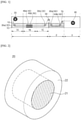
- FIG. 3 is a schematic diagram for describing the structure of the pre-lithiation roll.
- the device for producing a negative electrode according to the present invention includes a pre-lithiation bath 1 which is sequentially divided into an impregnation section 1A, a pre-lithiation section 1B, and an aging section 1C and contains a pre-lithiation solution 1D.
- the pre-lithiation bath 1 may be provided as a place where a negative electrode structure to be described below may be impregnated with an electrolyte solution, pre-lithiated, and aged while moving in the pre-lithiation bath.
- the pre-lithiation bath 1 is sequentially divided into the impregnation section 1A, the pre-lithiation section 1B, and the aging section 1C.
- the impregnation section 1A, the pre-lithiation section 1B, and the aging section 1C are not partitioned in a closed manner in the pre-lithiation bath 1 but abstractly partitioned according to the position of a negative electrode or a negative electrode structure in the pre-lithiation bath 1 and the process performed at the position of the negative electrode structure.
- the impregnation section 1A, the pre-lithiation section 1B, and the aging section 1C are abstractly partitioned through a dotted line in the pre-lithiation bath 1.
- the pre-lithiation bath 1 contains the pre-lithiation solution 1D.
- the pre-lithiation bath 1 is at least partially filled with the pre-lithiation solution 1D, and a negative electrode structure 10 unwound from a negative electrode roll 20 is introduced into the pre-lithiation solution 1D and moves through the sections of the pre-lithiation bath 1.
- the pre-lithiation bath 1 contains the pre-lithiation solution 1D
- the pre-lithiation solution 1D is also contained in the impregnation section 1A, the pre-lithiation section 1B, and the aging section 1C which are partitioned in the pre-lithiation bath 1.
- the pre-lithiation solution 1D may include a lithium salt and an organic solvent.
- the organic solvent is not particularly limited as long as it may serve as a medium through which ions involved in an electrochemical reaction can migrate.
- an ester-based solvent such as methyl acetate, ethyl acetate, ⁇ -butyrolactone, ⁇ -caprolactone, or the like
- an ether-based solvent such as dibutyl ether, tetrahydrofuran, or the like
- a ketone-based solvent such as cyclohexanone or the like
- an aromatic hydrocarbon-based solvent such as benzene, fluorobenzene, or the like
- a carbonate-based solvent such as dimethyl carbonate (DMC), diethyl carbonate (DEC), methyl ethyl carbonate (MEC), ethyl methyl carbonate (EMC), ethylene carbonate (EC), propylene carbonate (PC), or the like
- an alcohol-based solvent such as ethyl alcohol, isopropyl alcohol, or the like
- the lithium salt may include at least one selected from the group consisting of LiPF 6 , LiClO 4 , LiAsF 6 , LiBF 4 , LiSbF 6 , LiAlO 4 , LiAlCl 4 , LiCF 3 SO 3 , LiC 4 F 9 SO 3 , LiN(C 2 F 5 SO 3 ) 2 , LiN(C 2 F 5 SO 2 ) 2 , LiN(CF 3 SO 2 ) 2 .
- LiCl, LiI, and LiB(C 2 O 4 ) 2 and preferably includes LiPF 6 .
- a concentration of the lithium salt may range from 0.1 M to 3 M, and preferably, 0.5 M to 1.5 M based on the pre-lithiation solution, and it is preferable that the concentration of the lithium salt is within the above-described range so that the lithium salt can be sufficiently dissolved so that lithium ions can be smoothly intercalated into an active material.
- the pre-lithiation solution 1D may further include at least one additive selected from the group consisting of fluoroethylene carbonate (FEC), vinylene carbonate (VC), polystyrene (PS), succinonitrile, ethylene glycol bis(propionitrile) ether, and lithium bis(fluorosulfonyl)imide (LiFSI) and preferably further includes FEC.
- FEC fluoroethylene carbonate
- VC vinylene carbonate
- PS polystyrene
- succinonitrile ethylene glycol bis(propionitrile) ether
- LiFSI lithium bis(fluorosulfonyl)imide
- the additive may be included at 0.1 wt% to 15 wt%, and preferably, 0.5 wt% to 5 wt% with respect to the total weight of the pre-lithiation solution in the pre-lithiation solution in view of stabilizing the surface of a negative electrode active material to smoothly perform pre-lithiation.
- the size and shape of the pre-lithiation bath 1 may be appropriately designed in consideration of the degrees of the impregnation, pre-lithiation, and aging of a negative electrode structure and the movement distance of a negative electrode structure according to roll-to-roll processing, or the like.
- the size or length of the impregnation section 1A, the pre-lithiation section 1B, and the aging section 1C may be appropriately designed in consideration of the degrees of electrolyte impregnation, pre-lithiation, and aging of the negative electrode structure 10.
- the ratio of lengths of the impregnation section 1A, the pre-lithiation section 1B, and the aging section 1C is 1 to 10:1:0.5 to 21, and preferably, 1.5 to 5:1:1.8 to 10 for smoothly performing pre-lithiation.
- a temperature of the pre-lithiation bath 1 or the pre-lithiation solution 1D may range from 10 °C to 80 °C, preferably 20 °C to 60 °C. When the temperature thereof is within the above-described range, the pre-lithiation of a negative electrode and the diffusion of lithium ions into the negative electrode structure can smoothly proceed.
- the device for producing a negative electrode according to the present invention may further include a lithium metal counter electrode 40 which is disposed in the pre-lithiation section 1B and impregnated with the pre-lithiation solution 1D.
- the lithium metal counter electrode 40 may be disposed to be spaced apart from the negative electrode structure 10 and function as a counter electrode for the negative electrode structure 10 when the pre-lithiation is performed in an electrochemical charging manner in the device for producing a negative electrode.
- At least one lithium metal counter electrode 40 may be disposed to be spaced apart from the negative electrode structure 10 in the pre-lithiation section 1B, and as shown in FIG. 1 , a plurality of lithium metal counter electrodes 40a, 40b may be disposed in the pre-lithiation section 1B.
- the device for producing a negative electrode includes a negative electrode roll 20.
- the negative electrode roll 20 may be disposed outside the pre-lithiation solution 1D and allow the negative electrode structure to be wound and unwound.
- the negative electrode structure 10 may be provided in a wound state on the negative electrode roll 20 and then introduced into the pre-lithiation bath 1 or the pre-lithiation solution 1D while being unwound from the negative electrode roll 20.
- FIG. 2 is a schematic diagram of the structure of the negative electrode roll 20 that can be used in the present invention.
- the negative electrode roll 20 may include a rotatable drive shaft 21 and a winding portion 22 which is formed on the rotatable drive shaft 21 and on which the negative electrode structure 10 is wound, and from which the negative electrode structure 10 is unwound, and the winding portion 22 may include a non-conductor.
- the drive shaft 21 is rotatable, and, as the drive shaft 21 is rotated, the negative electrode structure 10 may be wound on or unwound from the winding portion 22.
- the drive shaft 21 may be connected to an electric motor and rotated by driving the electric motor.
- the drive shaft 21 may include one or more selected from the group consisting of iron, stainless steel, aluminum, and copper and preferably includes stainless steel in view of improving strength and durability.
- the winding portion 22 may be formed on the drive shaft 21, and the negative electrode structure 10 may be wound on and unwound from the winding portion 22.
- the winding portion 22 may be formed in the form of a layer on the drive shaft 21, and the negative electrode structure 10 may be wound on and unwound from the surface of the winding portion 22.
- the winding portion 22 may include a non-conductor.
- the winding portion 22 may be a portion with which the negative electrode structure to be wound is in direct contact.
- electrical insulation may be achieved between the negative electrode structure 10 and the drive shaft 21.
- an electric motor may be used to rotate the drive shaft 21, and current may flow outward by driving the electric motor.
- unwanted side reactions in the negative electrode structure which is caused by transferring the current generated from the electric motor from the drive shaft to the negative electrode structure, may be prevented.
- the winding portion 22 may include at least one non-conductor selected from the group consisting of ZrO 2 , TiO 2 , Al 2 O 3 , SiO 2 , polyethylene, polypropylene, polyvinyl chloride, polyether ether ketone (PEEK), polysiloxane (silicone), fluorine-containing rubber, nitrile-butadiene rubber (NBR), polytetrafluoroethylene (PTFE), and polyether ether ketone (PEEK) for electrical insulation between the drive shaft 21 and the negative electrode structure 10 and preferably includes polysiloxane in view of achieving excellent binding power to the negative electrode structure as well as insulation.
- PEEK polyether ether ketone
- the winding portion 22 may have a thickness of 0.1 cm to 2 cm, and preferably, 0.4 cm to 0.7 cm in view of making it easier to bind the negative electrode structure and achieve insulation.
- the diameter or width of the negative electrode roll 20 may be appropriately designed in consideration of the thickness and amount of the negative electrode structure to be wound.
- the negative electrode roll 20 may have a diameter of 3 cm to 50 cm, and preferably, 5 cm to 12 cm.
- the negative electrode roll 20 may have a width of 5 cm to 40 cm, and preferably, 10 cm to 20 cm.
- the device for producing a negative electrode includes one or more pre-lithiation rolls.
- a pre-lithiation roll 30 may be disposed inside the pre-lithiation solution and allow the negative electrode structure 10 unwound from the negative electrode roll 20 to be conveyed to or move in the pre-lithiation bath. At least one pre-lithiation roll 30 may be disposed, and for example, a plurality of pre-lithiation rolls 30a, 30b may be disposed inside the pre-lithiation solution as shown in FIG. 1 . The plurality of pre-lithiation rolls 30a, 30b may function to support the movement path of the negative electrode structure 10 or change the movement direction thereof.
- the pre-lithiation roll 30 includes an inner ring 31, an outer ring 32 which is formed on the inner ring and is rotatable, and a rolling element 33 which is disposed between the inner ring 31 and the outer ring 32.
- the outer ring 32 includes a non-conductor.
- the inner ring 31 may function to support the rolling element 33 and/or the outer ring 32. Specifically, the inner ring 31 may be fixedly disposed inside the pre-lithiation solution 1D of the pre-lithiation bath 1 so as not to be rotatable.
- the inner ring 31 may include one or more selected from the group consisting of iron, stainless steel, aluminum, and copper and preferably includes stainless steel in view of improving strength and durability.
- the inner ring 31 may have a thickness of 0.2 cm to 1 cm, and preferably, 0.3 cm to 0.7 cm in view of sufficiently supporting the outer ring, the rolling element, the negative electrode structure, and the like.
- the outer ring 32 is formed on the inner ring 31 and is rotatable.
- the outer ring 32 may be rotated independently of the inner ring 31 while being spaced a predetermined distance from the inner ring 31 by the rolling element 33 to be described below.
- the outer ring 32 includes a non-conductor.
- the outer ring 32 provides a surface where the pre-lithiation roll 30 and the negative electrode structure 10 are in contact.
- the current applied to the negative electrode structure 10 when pre-lithiation is performed by electrochemical charging may not be consumed externally or wasted through the pre-lithiation roll 30. Accordingly, low process loss in the pre-lithiation by electrochemical charging is achieved, the negative electrode structure is uniformly and stably pre-lithiated, and the degree of pre-lithiation is easily controlled. Therefore, since a negative electrode produced using the device for producing a negative electrode according to the present invention is uniformly and stably pre-lithiated, battery characteristics such as lifetime characteristics and the like can be improved.
- the non-conductor is preferably a material having electrical insulation and strength and, specifically, may include one or more selected from the group consisting of a ceramic compound and a non-conductive polymer.
- the ceramic compound included in the outer ring 32 may be one or more metal oxide, wherein the metal is selected from the group consisting of silicon (Si), aluminum (Al), titanium (Ti), zirconium (Zr), calcium (Ca), magnesium (Mg), yttrium (Y), and cerium (Ce) in view of achieving high insulation and high strength, is preferably one or more selected from the group consisting of ZrO 2 , Al 2 O 3 , TiO 2 , and SiO 2 in view of achieving excellent stability with respect to the pre-lithiation solution 1D or an organic solvent as well as high insulation and strength, and is more preferably ZrO 2 .
- the non-conductive polymer included in the outer ring 32 may be one or more selected from the group consisting of polytetrafluoroethylene (PTFE), polyethylene, polypropylene, polyvinyl chloride, and polyether ether ketone (PEEK) in view of achieving high insulation and high strength, is preferably one or more selected from the group consisting of PTFE, polypropylene, and PEEK in view of achieving excellent stability with respect to the pre-lithiation solution 1D or an organic solvent as well as high insulation and strength, and is more preferably PEEK.
- PTFE polytetrafluoroethylene
- PEEK polyether ether ketone
- the outer ring 32 may have a thickness of 0.2 cm to 1 cm, and preferably, 0.4 cm to 0.7 cm in view of achieving excellent insulation as well as sufficient strength and durability.
- the rolling element 33 may be disposed between the inner ring 31 and the outer ring 32 and operated or rotated.
- the outer ring 32 may be rotated by the operation or rotation of the rolling element 33.
- the rolling element 33 may be used without limitation as long as it is a rolling element generally used in the roll structure and may be, for example, a rolling element in the form of a ball or a roller.
- the pre-lithiation roll 30 may further include a cage 34 which is disposed between the inner ring 31 and the outer ring 32 and accommodates the rolling element 33.
- the cage 34 may function to allow the rolling element 33 to be disposed at a predetermined interval and position between the inner ring 31 and the outer ring 32 and prevent the rolling element 33 from being separated from the pre-lithiation roll.
- the diameter or width of the pre-lithiation roll 30 may be appropriately designed in consideration of the thickness and amount of the negative electrode structure to be conveyed.
- the pre-lithiation roll 30 may have a diameter of 1.5 cm to 25 cm, and preferably, 2.5 cm to 7.5 cm.
- the pre-lithiation roll 30 may have a width of 5 cm to 40 cm, and preferably, 10 cm to 20 cm.
- the device for producing a negative electrode according to the present invention may further include: a washing bath 2 containing an organic solvent 2A; a first conveying roll 50 which is disposed between the pre-lithiation bath 1 and the washing bath 2, wherein the first conveying roll allows the negative electrode structure 10 to be conveyed from the pre-lithiation bath 1 to the washing bath 2; and at least one washing roll 60 which is disposed inside the organic solvent 2A, wherein the one or more washing rolls allow the negative electrode structure 10 conveyed to the washing bath 2 to move in the washing bath 2.
- the washing bath 2 may be disposed independently of the pre-lithiation bath 1 and provided as a place for washing the negative electrode structure 10 having been pre-lithiated.
- the negative electrode structure 10 is introduced into the washing bath 2 from the pre-lithiation bath 1 and moves through the washing bath 2, and accordingly, impurities remaining in the negative electrode structure may be removed.
- the washing bath 2 contains the organic solvent 2A, and specifically, may contain the organic solvent 2A not containing a lithium salt.
- the negative electrode structure is washed while moving in the organic solvent not containing a lithium salt.
- the organic solvent used in the pre-lithiation solution may be used, and, specifically, at least one selected from the group consisting of dimethyl carbonate (DMC), ethyl methyl carbonate (EMC), and ethylene carbonate (EC) may be used.
- DMC dimethyl carbonate
- EMC ethyl methyl carbonate
- EC ethylene carbonate
- the length of the washing bath 2 or the movement distance of the negative electrode structure 10 in the washing bath 2 may be 0.1 times to 5 times, and preferably, 0.5 times to 2 times the length of the pre-lithiation section 1B. Within the above-described range, impurities remaining in the negative electrode structure can be smoothly removed.
- the first conveying roll 50 may be disposed between the pre-lithiation bath 1 and the washing bath 2 and allow the negative electrode structure 10 to be conveyed from the pre-lithiation bath 1 to the washing bath 2.
- the washing roll 60 may be disposed inside the organic solvent 2A and allow the negative electrode structure 10 conveyed to the washing bath 2 through the first conveying roll 50 to move in the washing bath 2.
- washing roll 60 There may be at least one washing roll 60, and, for example, a plurality of washing rolls 60a, 60b may be disposed inside the organic solvent as shown in FIG. 1 .
- the first conveying roll 50 and the washing roll 60 may be identical to the pre-lithiation roll 30, which is preferred in view of achieving high strength and improving stability with respect to the organic solvent.
- the device for producing a negative electrode according to the present invention may further include: a drying part 3; a second conveying roll 70 which is disposed between the washing bath 2 and the drying part 3, wherein the second conveying roll allows the negative electrode structure 10 to be conveyed from the washing bath 2 to the drying part 3 and move in the drying part 3; and a collecting roll 80 which allows the negative electrode structure 10 conveyed to the drying part 3 to be wound and unwound.
- the drying part 3 may be provided as a place for drying the negative electrode structure 10 having passed through the pre-lithiation bath 1 and the washing bath 2.
- the drying part 3 contains air or an inert gas.
- the inert gas may be at least one selected from the group consisting of Ar, N 2 , and He.
- a temperature of the drying part 3 may range from 10 °C to 80 °C, preferably 20 °C to 60 °C, and more preferably 25 °C to 40 °C. It is preferable that the temperature of the drying part is within the above-described range so that the negative electrode structure can be prevented from being oxidized and maintained in the pre-lithiated state.
- the length of the drying part 3 or the movement distance of the negative electrode structure 10 in the drying part 3 may be 0.1 times to 5 times, and preferably, 0.5 times to 2 times the length of the pre-lithiation section 1B. It is preferable that the length of the drying part 3 or the movement distance of the negative electrode structure 10 in the drying part 3 is within the above-described range so that the organic solvent remaining in the negative electrode structure can be smoothly removed, and damage to the negative electrode structure which may be caused by the organic solvent remaining in the negative electrode structure for a long time can be prevented.
- the second conveying roll 70 may be disposed between the washing bath 2 and the drying part 3 and allow the negative electrode structure 10 to be conveyed from the washing bath 2 to the drying part 3 and move in the drying part 3.
- the collecting roll 80 may allow the negative electrode structure 10 conveyed to the drying part 3 to be wound and unwound.
- the collecting roll 80 may function to collect the negative electrode structure having been pre-lithiated, washed, and dried.
- the second conveying roll 70 may be identical to the above-described pre-lithiation roll 30.
- the collecting roll 80 may be identical to the above-described negative electrode roll 20.
- the present invention provides a method of producing a negative electrode using the above-described device for producing a negative electrode.
- the method of producing a negative electrode according to the present invention includes: fabricating the above-described device for producing a negative electrode; winding a negative electrode structure 10 around a negative electrode roll 20; impregnating the negative electrode structure 10 with a pre-lithiation solution 1D while unwinding the negative electrode structure 10 from the negative electrode roll 20 and moving the same through an impregnation section 1A; pre-lithiating the negative electrode structure 10 while moving the negative electrode structure 10 from the impregnation section 1A through a pre-lithiation section 1B; and aging the negative electrode structure 10 while moving the negative electrode structure 10 from the pre-lithiation section 1B through an aging section 1C, wherein the pre-lithiation is performed by placing a lithium metal counter electrode 40, which is spaced apart from the negative electrode structure 10 and impregnated with the pre-lithiation solution 1D, in the pre-lithiation section 1B and electrochemically charging the negative electrode structure 10, and the negative electrode structure 10 moves through the impreg
- the negative electrode structure moves in the pre-lithiation solution of the pre-lithiation bath by the pre-lithiation roll having an outer ring including a non-conductor. Accordingly, the current applied to the negative electrode structure when pre-lithiation is performed by electrochemical charging may not be consumed externally or wasted through the roll structure. Therefore, low process loss in the pre-lithiation by electrochemical charging is achieved, the negative electrode structure is uniformly and stably pre-lithiated, and the degree of pre-lithiation is easily controlled. Therefore, since a negative electrode produced using the device for producing a negative electrode according to the present invention is uniformly and stably pre-lithiated, battery characteristics such as lifetime characteristics and the like can be improved.
- a negative electrode of the present invention since a negative electrode is pre-lithiated in a roll-to-roll manner, quality consistency of a product and processability can be improved.
- the method of producing a negative electrode according to the present invention includes fabricating the above-described device for producing a negative electrode.
- the configuration and form of the device for producing a negative electrode have been described above.
- the method of producing a negative electrode according to the present invention includes winding a negative electrode structure 10 on a negative electrode roll 20.
- the negative electrode structure 10 includes a negative electrode current collector and a negative electrode active material layer formed on at least one surface of the negative electrode current collector.
- the negative electrode current collector is not particularly limited as long as it does not cause a chemical change in the battery and has high conductivity.
- the negative electrode current collector copper, stainless steel, aluminum, nickel, titanium, calcined carbon, copper or stainless steel whose surface has been treated with carbon, nickel, titanium, silver, or the like, an aluminum-cadmium alloy, or the like may be used.
- the negative electrode current collector may typically have a thickness of 3 to 500 ⁇ m.
- the negative electrode current collector may have fine irregularities formed on a surface thereof to increase the adhesion of a negative electrode active material.
- the negative electrode current collector may be used in any of various forms such as a film, a sheet, a foil, a net, a porous material, a foam, a non-woven fabric, and the like.
- the negative electrode active material layer is formed on at least one surface of the negative electrode current collector.
- the negative electrode active material layer may be formed on one surface or both surfaces of the negative electrode current collector and is preferably formed on both surfaces of the negative electrode current collector in view of the utilization of the negative electrode active material and the improvement of cell energy density.
- the negative electrode active material layer includes a negative electrode active material.
- the negative electrode active material may include at least one selected from the group consisting of a carbon-based active material and a silicon-based active material.
- the silicon-based active material may impart excellent capacity characteristics and excellent durability to the negative electrode for a secondary battery or the secondary battery of the present invention.
- the silicon-based active material may include a compound represented by SiO x (0 ⁇ x ⁇ 2). Since SiO 2 does not react with lithium ions, it is not possible to store lithium. Therefore, it is preferable that x is within the above-described range, and the silicon-based oxide is more preferably SiO.
- the silicon-based active material may have an average particle diameter (D 50 ) of 1 ⁇ m to 30 ⁇ m, and preferably, 3 ⁇ m to 15 ⁇ m in view of ensuring structural stability and reducing side reactions with an electrolyte during charging and discharging.
- D 50 average particle diameter
- the carbon-based active material may impart excellent cycle characteristics or excellent battery lifetime characteristics to the negative electrode for a secondary battery or the secondary battery of the present invention.
- the carbon-based active material may include at least one selected from the group consisting of artificial graphite, natural graphite, hard carbon, soft carbon, carbon black, acetylene black, Ketjen black, Super P, graphene, and fibrous carbon and preferably includes at least one selected from the group consisting of artificial graphite and natural graphite.
- the carbon-based active material may have an average particle diameter (D 50 ) of 10 ⁇ m to 30 ⁇ m, and preferably, 15 ⁇ m to 25 ⁇ m in view of ensuring structural stability and reducing side reactions with an electrolyte during charging and discharging.
- D 50 average particle diameter
- the negative electrode active material preferably includes both the silicon-based active material and the carbon-based active material in view of improving both capacity characteristics and cycle characteristics. More specifically, the negative electrode active material preferably includes the carbon-based active material and the silicon-based active material in a weight ratio of 50:50 to 95:5, and more preferably, in a weight ratio of 60:40 to 80:20. It is preferable that the weight ratio of the carbon-based active material and the silicon-based active material is within the above-described range in view of improving both capacity characteristics and cycle characteristics.
- the negative electrode active material may be included at 60 wt% to 99 wt%, and preferably, 75 wt% to 95 wt% with respect to the total weight of the negative electrode active material layer in the negative electrode active material layer.
- the negative electrode active material layer may further include a binder and/or a conductive material in addition to the negative electrode active material.
- the negative electrode active material layer may further include a binder and/or a conductive material in addition to the negative electrode active material.
- the binder is used to improve adhesion between the negative electrode active material layer and the negative electrode current collector to accordingly improve battery performance.
- the binder may include, for example, at least one selected from the group consisting of a polyvinylidene fluoride-hexafluoropropylene copolymer (PVDF-co-HFP), polyvinylidene fluoride (PVDF), polyacrylonitrile, polymethyl methacrylate, polyvinyl alcohol, carboxymethylcellulose (CMC), starch, hydroxypropylcellulose, regenerated cellulose, polyvinylpyrrolidone, tetrafluoroethylene, polyethylene, polypropylene, polyacrylic acid, an ethylenepropylene-diene monomer (EPDM), a sulfonated EPDM, styrene butadiene rubber (SBR), fluorine rubber, polymers in which hydrogens thereof have been substituted with Li, Na, Ca, or the like, and various copolymers thereof.
- the binder may be included at 0.5 wt% to 10 wt%, and preferably, 1 wt% to 5 wt% with respect to the total weight of the negative electrode active material layer in the negative electrode active material layer.
- the conductive material is not particularly limited as long as it does not cause a chemical change in the produced battery and has conductivity.
- the conductive material graphite such as natural graphite, artificial graphite, or the like; carbon black such as carbon black, acetylene black, Ketjen black, channel black, furnace black, lamp black, thermal black, or the like; a conductive fiber such as carbon fibers, metal fibers, or the like; a conductive tube such as carbon nanotubes or the like; fluorocarbon powder; a metal powder such as aluminum powder, nickel powder, or the like; a conductive whisker consisting of zinc oxide, potassium titanate, or the like; a conductive metal oxide such as titanium oxide or the like; or a conductive material such as a polyphenylene derivative or the like may be used.
- the conductive material may be included at 0.5 wt% to 10 wt%, and preferably, 1 wt% to 5 wt% with respect to the total weight of the negative electrode active material layer in the negative electrode active material layer.
- the negative electrode active material layer may have a thickness of 10 ⁇ m to 100 ⁇ m, and preferably, 50 ⁇ m to 80 ⁇ m.
- the method of producing a negative electrode according to the present invention includes impregnating the negative electrode structure 10 with a pre-lithiation solution 1D while unwinding the negative electrode structure 10 from the negative electrode roll 20 and moving the same through an impregnation section 1A.
- the negative electrode structure 10 unwound from the negative electrode roll 20 is introduced into the pre-lithiation bath and moves through the impregnation section. Specifically, as shown in FIG. 1 , the negative electrode structure 10 unwound from the negative electrode roll 20 may move through the impregnation section 1A along pre-lithiation rolls 30a, 30b.
- electrolyte impregnation is achieved by the pre-lithiation solution 1D contained in the impregnation section 1A. Due to the electrolyte impregnation, lithium ions may be more smoothly intercalated in the pre-lithiation of the negative electrode structure 10.
- the time taken for the negative electrode structure 10 to move through the impregnation section 1A is 1 times to 10 times, more preferably, 1.5 times to 5 times the time taken for the negative electrode structure 10 to move through a pre-lithiation section 1B to be described below.
- the time is within the above-described range, it is possible to form a more uniform passivation film in pre-lithiation to be described below and perform pre-lithiation.
- the method of producing a negative electrode according to the present invention includes pre-lithiating the negative electrode structure 10 while introducing the negative electrode structure 10 from the impregnation section 1A and moving the same through a pre-lithiation section 1B.
- the negative electrode structure 10 passes through the impregnation section 1A and enters the pre-lithiation section 1B.
- the pre-lithiation section 1B the negative electrode structure 10 is pre-lithiated, and lithium ions are intercalated into the negative electrode active material layer or negative electrode active material. Accordingly, the irreversible capacity of the negative electrode active material is removed, and a passivation film is formed.
- the pre-lithiation is performed while the negative electrode structure 10 moves through the pre-lithiation section 1B.
- the time taken for the negative electrode structure 10 to move through the pre-lithiation section 1B may range from 5 minutes to 120 minutes, preferably 10 minutes to 90 minutes, and more preferably 15 minutes to 40 minutes. It is preferable that the time is within the above-described range so that it is possible to more uniformly pre-lithiate the negative electrode active material and prevent an increase in by-products in a negative electrode due to excessive pre-lithiation.
- the pre-lithiation is performed by disposing a lithium metal counter electrode 40, which is spaced apart from the negative electrode structure 10 and impregnated with the pre-lithiation solution 1D, in the pre-lithiation section 1B and electrochemically charging the negative electrode structure 10.
- both a negative electrode structure and a lithium metal need to be wound on a negative electrode roll.
- the method of producing a negative electrode according to the present invention makes it possible to adjust an intercalation rate of lithium ions and prevent volume expansion of or damage to a negative electrode active material due to excessive lithium intercalation by performing pre-lithiation by an electrochemical charging method using a lithium metal spaced apart from the negative electrode structure as a counter electrode, as compared with the conventional method in which a negative electrode structure and a lithium metal are in direct contact.
- the method of producing a negative electrode of the present invention since the outer ring of the pre-lithiation roll 30, which is used to convey the negative electrode structure, includes a non-conductor, the current applied to the negative electrode structure when pre-lithiation is performed by electrochemical charging may not be consumed externally through the outer ring but may be mainly used in the pre-lithiation of the negative electrode structure or the intercalation of lithium. Therefore, the method of producing a negative electrode according to the present invention achieves remarkably low process loss in the electrochemical charging and allows the negative electrode structure to be uniformly and stably pre-lithiated, resulting in improvement of lifetime characteristics of the produced negative electrode.
- the electrochemical charging may be performed by an oxidation-reduction reaction using an electrochemical charging/discharging device.
- Lithium metal counter electrodes 40a, 40b may function as a counter electrode for the negative electrode structure 10.
- the lithium metal counter electrodes 40a, 40b are spaced apart from the negative electrode structure 10 in the pre-lithiation bath 1 to prevent an electrical short circuit with the negative electrode structure 10 during the electrochemical charging.
- the pre-lithiation may be performed at a current density of 0.2 mA/cm 2 to 10 mA/cm 2 , and preferably, 2 mA/cm 2 to 6 mA/cm 2 .
- the electrochemical charging is performed at a current density within the above-described range, the negative electrode active material can be stably and uniformly pre-lithiated.
- the pre-lithiation may be performed by electrochemical charging to 5 to 50%, preferably, 15 to 35% of the state of charge (SoC) of the negative electrode structure. It is preferable that the pre-lithiation is performed by electrochemical charging to the above-described range so that a passivation film can be uniformly and stably formed on the surface of the negative electrode structure, and thus the reversible capacity of a battery can be improved, resulting in improvement of cycle characteristics of the battery.
- SoC state of charge
- the method of producing a negative electrode according to the present invention includes aging the negative electrode structure 10 while introducing the negative electrode structure 10 from the pre-lithiation section 1B and moving the same through an aging section 1C.
- the negative electrode structure 10 After the negative electrode structure 10 passes through the pre-lithiation section 1B, the negative electrode structure enters the aging section 1C.
- lithium ions intercalated by the pre-lithiation may be more uniformly diffused on the surface and in the inside of the negative electrode active material.
- the aging process is not performed after the pre-lithiation, lithium ions are not uniformly diffused into the negative electrode active material, and thus it may be difficult to sufficiently remove the irreversible capacity even though the pre-lithiation has been performed, and charging and discharging may not uniformly occur after a negative electrode is produced.
- the time taken for the negative electrode structure 10 to move through the aging section 1C is 0.5 times to 21 times, preferably, 1.8 times to 10 times the time taken for the negative electrode structure 10 to move through the pre-lithiation section 1B. It is preferable that the time is within the above-described range so that lithium ions can be more uniformly diffused into the negative electrode active material, and detachment of the negative electrode active material layer from the current collector due to excessive aging or an increase in resistance due to an increase in thickness of a surface coating of a negative electrode can be prevented.
- the method of producing a negative electrode according to the present invention may further include washing the negative electrode structure 10 by taking the negative electrode structure 10 out of the pre-lithiation bath 1, introducing the negative electrode structure into a washing bath 2 containing an organic solvent 2A, and moving the same through the washing bath 2.
- the method of producing a negative electrode according to the present invention further includes the washing process after the pre-lithiation and aging of the negative electrode structure 10, impurities remaining in the negative electrode structure may be removed.
- the washing process may be performed by taking the negative electrode structure 10 out of the pre-lithiation bath 1 and introducing the same into the separately arranged washing bath 2.
- the washing process may be performed by discharging the negative electrode structure 10 from the pre-lithiation bath 1 and introducing the same into the washing bath 2 through a first conveying roll 50 disposed between the pre-lithiation bath 1 and the washing bath 2, and the negative electrode structure 10 may be washed while moving in the washing bath 2.
- the movement of the negative electrode structure 10 in the washing bath 2 may be performed by at least one separately arranged washing roll 60.
- the washing roll 60 may be disposed inside the organic solvent 2A and allow the negative electrode structure 10 conveyed to the washing bath 2 to move in the washing bath.
- the washing bath 2 contains the organic solvent 2A, specifically, the organic solvent 2A not containing a lithium salt.
- the aged negative electrode structure is washed while moving in the solution not containing a lithium salt.
- the organic solvent 2A the organic solvent listed in the description of the pre-lithiation solution may be used.
- the time taken for the negative electrode structure 10 to move through the washing bath 2 is 0.1 times to 5 times, more preferably, 0.5 times to 2 times the time taken for the negative electrode structure 10 to move through the pre-lithiation section 1B.
- the time is within the above-described range, impurities remaining in the negative electrode structure can be smoothly removed.
- washing bath 2 Details of the washing bath 2, the organic solvent 2A, the first conveying roll 50, and the washing roll 60 have been described above.
- the method of producing a negative electrode according to the present invention may further include drying the washed negative electrode structure 10.
- the organic solvent remaining in the negative electrode structure after the impregnation, pre-lithiation, aging, and/or washing processes may be removed.
- the drying process may be performed by taking the washed negative electrode structure 10 out of the washing bath 2 and introducing the same into a separately arranged drying part 3.
- a second conveying roll 70 may be disposed between the washing bath 2 and the drying part 3, and the negative electrode structure 10 may move in the drying part 3 by the second conveying roll 70.
- the drying process may be performed by air or an inert gas.
- the inert gas may be at least one selected from the group consisting of Ar, N 2 , and He.
- the drying process may be performed at 10 °C to 80 °C, preferably 20 °C to 60 °C, and more preferably 25 °C to 40 °C. It is preferable that the drying process is performed at a temperature within the above-described range so that the negative electrode structure can be prevented from being oxidized and maintained in the pre-lithiated state.
- the time taken to dry the washed negative electrode structure 10 may be 0.1 times to 5 times, and preferably, 0.5 times to 2 times the time taken for the negative electrode structure 10 to move through the pre-lithiation section. It is preferable that the time is within the above-described range so that the organic solvent remaining in the negative electrode structure can be smoothly removed, and damage to the negative electrode structure which may be caused by the organic solvent remaining in the negative electrode structure for a long time can be prevented.
- a collecting roll 80 may be installed, and the negative electrode structure 10 that has moved through the drying part 3 may be wound on the collecting roll 80.
- drying part 3 Details of the drying part 3, the second conveying roll 70, and the collecting roll 80 have been described above.
- the method of producing a negative electrode according to the present invention may further include producing a negative electrode by unwinding the negative electrode structure 10 from the collecting roll 80 and cutting the same.
- the negative electrode may be assembled with a positive electrode, a separator, an electrolyte, and the like as described below, and accordingly, a secondary battery, specifically a lithium secondary battery, may be produced.
- a negative electrode produced by the above-described method has improved reversibility, improved initial efficiency, and improved lifetime characteristics because uniform and stable pre-lithiation is possible. Accordingly, the negative electrode produced by the method of the present invention is preferably applied to a secondary battery, specifically, a lithium secondary battery.
- the secondary battery may include the negative electrode for a secondary battery which is produced by the above-described method, a positive electrode disposed to face the negative electrode for a secondary battery, a separator interposed between the negative electrode for a secondary battery and the positive electrode, and an electrolyte. Details of the negative electrode for a secondary battery have been described above, and the positive electrode, separator, and electrolyte may be used without limitation as long as they are typically used in a lithium secondary battery.
- the secondary battery is useful in the field of portable devices, such as mobile phones, notebook computers, digital cameras, and the like, and electric vehicles such as hybrid electric vehicles (HEVs).
- portable devices such as mobile phones, notebook computers, digital cameras, and the like
- electric vehicles such as hybrid electric vehicles (HEVs).
- HEVs hybrid electric vehicles
- the secondary battery may be applied to a battery module including the secondary battery as a unit cell or a battery pack including the battery module.
- the battery module or battery pack may be used as a power source of one or more medium-to-large-sized devices selected from a power tool; electric vehicles (EVs), hybrid electric vehicles, and plug-in hybrid electric vehicles (PHEVs); and a system for storing electric power.
- a power tool electric vehicles (EVs), hybrid electric vehicles, and plug-in hybrid electric vehicles (PHEVs); and a system for storing electric power.
- EVs electric vehicles
- PHEVs plug-in hybrid electric vehicles
- a pre-lithiation bath made of stainless steel and having a width, length, and height of 100 cm x 20 cm x 50 cm was provided.
- a pre-lithiation solution was added to the pre-lithiation bath so that the pre-lithiation solution was filled to 20% of the height of the pre-lithiation bath.
- the pre-lithiation bath was maintained at a temperature of 25 °C.
- the pre-lithiation solution was prepared by adding LiPF 6 as a lithium salt at a concentration of 1 M to an organic solvent in which ethylene carbonate (EC) and ethyl methyl carbonate (EMC) were mixed in a volume ratio of 30:70 and adding fluoroethylene carbonate (FEC) as an additive at 2 wt% with respect to the total weight of the pre-lithiation solution.
- LiPF 6 lithium salt
- EMC ethyl methyl carbonate
- FEC fluoroethylene carbonate
- the pre-lithiation bath was divided into an impregnation section, a pre-lithiation section, and an aging section.
- an impregnation section In the pre-lithiation solution of the pre-lithiation bath, two pre-lithiation rolls were installed respectively at the start point of the impregnation section and the end point of the aging section.
- lithium metal counter electrodes were installed to be spaced apart from the movement path of a negative electrode structure.
- impregnation section pre-lithiation section
- aging section in the pre-lithiation bath were partitioned in a length ratio of 2:1:2.
- a washing bath made of stainless steel and having a width, length, and height of 20 cm x 20 cm x 50 cm was provided.
- a first conveying roll was installed between the pre-lithiation bath and the washing bath.
- the washing bath contained dimethyl carbonate (DMC) as an organic solvent so that DMC was filled to 20% of the height of the washing bath.
- DMC dimethyl carbonate
- a drying part made of stainless steel and having a width, length, and height of 20 cm x 20 cm x 50 cm was provided.
- a temperature of the drying part was 25 °C, and the drying part was filled with air.
- a second conveying roll was installed between the washing bath and the drying part.
- a collecting roll was installed at the end point of the drying part.
- a roll including a drive shaft made of stainless steel and having a diameter of 6.5 cm and a winding portion formed of polysiloxane (silicone) on the drive shaft and having a thickness of 0.5 cm was used as the negative electrode roll and the collecting roll.
- the drive shafts of the negative electrode roll and the collecting roll were connected to an electric motor capable of rotating the drive shafts.
- the negative electrode roll and the collecting roll had a diameter of 7 cm and a width of 20 cm.
- the pre-lithiation roll, the washing roll, the first conveying roll, and the second conveying roll a roll including an inner ring made of stainless steel and having a thickness of 0.5 cm, an outer ring made of polyether ether ketone (PEEK) and having a thickness of 0.5 cm, a rolling element made of stainless steel and disposed between the inner ring and the outer ring, and a cage accommodating the rolling element was provided.
- the pre-lithiation roll, the washing roll, the first conveying roll, and the second conveying roll had a diameter of 5 cm and a width of 20 cm.
- the inner rings of the pre-lithiation roll, the washing roll, the first conveying roll, and the second conveying roll were fixedly disposed, and the rolls were installed so that the outer ring is rotated by rotating and operating the rolling element.
- a negative electrode active material was prepared by mixing natural graphite (average particle diameter (D 50 ): 20 ⁇ m) and SiO (average particle diameter (D 50 ): 5 ⁇ m) in a weight ratio of 70:30.
- the negative electrode active material Denka black as a conductive material, styrene butadiene rubber (SBR) as a binder, and carboxymethylcellulose (CMC) as a thickener were mixed in a weight ratio of 92:3:3.5:1, thereby preparing a negative electrode slurry.
- SBR styrene butadiene rubber
- CMC carboxymethylcellulose
- the negative electrode slurry was applied onto both surfaces of a copper current collector (thickness: 8 ⁇ m), and the resulting copper current collector was roll-pressed and dried in a 130 °C vacuum oven for 12 hours to form a negative electrode active material layer (thickness: 70 ⁇ m) on both surfaces of the copper negative electrode current collector, thereby fabricating a negative electrode structure.
- the negative electrode structure was wound on the negative electrode roll.
- the negative electrode structure was introduced into and moved through the pre-lithiation bath at a speed of 1 cm/min while being unwound from the negative electrode roll.
- the unwound negative electrode structure entered the impregnation section and was moved therethrough for 40 minutes, thereby impregnating the negative electrode structure with an electrolyte solution.
- the negative electrode structure was pre-lithiated by electrochemically charging the negative electrode structure and the lithium metal counter electrodes spaced apart from the negative electrode structure to 18.5% SoC of the negative electrode structure at a current density of 4.68 mA/cm 2 using an electrochemical charging/discharging device (WBCS3000 manufactured by WonATech).
- the negative electrode structure having passed through the pre-lithiation section entered the aging section and was moved therethrough for 40 minutes, thereby aging the negative electrode structure.
- the aged negative electrode structure was taken out of the pre-lithiation bath and introduced into the washing bath through the first conveying roll. Also, the negative electrode structure was washed while moving in the washing bath through the two washing rolls. The time taken for the negative electrode structure to move in the washing bath was 20 minutes.
- the washed negative electrode structure was conveyed from the washing bath to the drying part through the second conveying roll.
- the negative electrode structure was dried for 20 minutes while moving in the drying part.
- the negative electrode structure was collected while being wound on the collecting roll.
- a negative electrode of Example 2 was produced in the same manner using the same device as in Example 1 except that an outer ring of the pre-lithiation roll was made of polytetrafluoroethylene (PTFE, Teflon).
- PTFE polytetrafluoroethylene
- a negative electrode of Example 3 was produced in the same manner using the same device as in Example 1 except that an outer ring of the pre-lithiation roll was made of polypropylene (PP).
- PP polypropylene
- a negative electrode of Example 4 was produced in the same manner using the same device as in Example 1 except that an outer ring of the pre-lithiation roll was made of ZrO 2 .
- a negative electrode of Example 5 was produced in the same manner using the same device as in Example 1 except that an outer ring of the pre-lithiation roll had a thickness of 0.3 cm.
- a negative electrode of Example 6 was produced in the same manner using the same device as in Example 1 except that an outer ring of the pre-lithiation roll had a thickness of 0.8 cm.
- a negative electrode of Comparative Example 1 was produced in the same manner using the same device as in Example 1 except that an outer ring of the pre-lithiation roll was made of stainless steel.
- a negative electrode of Comparative Example 2 was produced in the same manner using the same device as in Example 1 except that an outer ring of the pre-lithiation roll was made of iron.
- the negative electrodes produced in Examples 1 to 6 and Comparative Examples 1 and 2 were cut into an area of 1.4875 cm 2 .
- the negative electrode for a secondary battery according to each of Examples 1 to 6 and Comparative Examples 1 and 2 and a lithium metal counter electrode as a positive electrode were provided, a polypropylene separator was interposed between the negative electrode and the positive electrode, and an electrolyte was injected, thereby producing a half-cell lithium secondary battery.
- the electrolyte was prepared by adding LiPF 6 as a lithium salt at a concentration of 1 M to an organic solvent in which ethylene carbonate (EC) and ethyl methyl carbonate (EMC) were mixed in a volume ratio of 30:70 and adding fluoroethylene carbonate (FEC) as an additive at 2 wt% with respect to the total weight of the pre-lithiation solution.
- the negative electrodes produced in Examples 1 to 6 and Comparative Examples 1 and 2 were cut into a size of 3 cm ⁇ 4 cm.
- LiNi 0.8 Co 0.1 Mn 0.1 O 2 as a positive electrode active material, Super C as a conductive material, and polyvinylidene fluoride (PVDF) as a binder were mixed in a weight ratio of 97:1.5:1.5 to prepare a positive electrode slurry, the positive electrode slurry was applied onto an aluminum current collector, and the resulting aluminum current collector was roll-pressed and dried at 130 °C, thereby producing a positive electrode.
- PVDF polyvinylidene fluoride
- a polypropylene separator was interposed between the negative electrode according to each of Examples 1 to 6 and Comparative Examples 1 and 2 and the above-produced positive electrode, and an electrolyte was injected, thereby producing a lithium secondary battery.
- the electrolyte was prepared by adding LiPF 6 as a lithium salt at a concentration of 1 M to an organic solvent in which EC and EMC were mixed in a volume ratio of 30:70 and adding FEC as an additive at 2 wt% with respect to the total weight of the pre-lithiation solution.
- the discharge capacity and capacity retention rate of the lithium secondary batteries according to Examples 1 to 6 and Comparative Examples 1 and 2 were evaluated using an electrochemical charging/discharging device.
- the lithium secondary batteries were charged while applying current at a current density of 0.1 C-rate up to 4.2 V and discharged at the same current density up to 2.5 V.
- Capacity retention rate % Discharge capacity at 100 th cycle / Discharge capacity at 1 st cycle ⁇ 100 [Table 2] Capacity retention rate (%) @ 100 th cycle Example 1 94
- Example 2 93 Example 3 93
- Example 5 92 Example 6 93 Comparative Example 1 82 Comparative Example 2 81
Landscapes
- Chemical & Material Sciences (AREA)
- Engineering & Computer Science (AREA)
- General Chemical & Material Sciences (AREA)
- Manufacturing & Machinery (AREA)
- Chemical Kinetics & Catalysis (AREA)
- Electrochemistry (AREA)
- Materials Engineering (AREA)
- Dispersion Chemistry (AREA)
- Battery Electrode And Active Subsutance (AREA)
- Secondary Cells (AREA)
Applications Claiming Priority (2)
| Application Number | Priority Date | Filing Date | Title |
|---|---|---|---|
| KR1020190057950A KR20200132432A (ko) | 2019-05-17 | 2019-05-17 | 음극 제조장치 및 음극의 제조방법 |
| PCT/KR2020/006055 WO2020235841A1 (fr) | 2019-05-17 | 2020-05-07 | Dispositif de fabrication d'électrode négative et procédé de fabrication d'électrode négative |
Publications (2)
| Publication Number | Publication Date |
|---|---|
| EP3958355A1 true EP3958355A1 (fr) | 2022-02-23 |
| EP3958355A4 EP3958355A4 (fr) | 2022-06-22 |
Family
ID=73458628
Family Applications (1)
| Application Number | Title | Priority Date | Filing Date |
|---|---|---|---|
| EP20809469.8A Pending EP3958355A4 (fr) | 2019-05-17 | 2020-05-07 | Dispositif de fabrication d'électrode négative et procédé de fabrication d'électrode négative |
Country Status (5)
| Country | Link |
|---|---|
| US (1) | US12113195B2 (fr) |
| EP (1) | EP3958355A4 (fr) |
| KR (1) | KR20200132432A (fr) |
| CN (1) | CN113826238B (fr) |
| WO (1) | WO2020235841A1 (fr) |
Cited By (1)
| Publication number | Priority date | Publication date | Assignee | Title |
|---|---|---|---|---|
| WO2023161425A1 (fr) * | 2022-02-25 | 2023-08-31 | Forschungszentrum Jülich GmbH | Procédé de chargement préalable amélioré d'électrodes de batterie avec des ions métalliques et électrodes de batterie préalablement chargées à propriétés électriques améliorées |
Families Citing this family (4)
| Publication number | Priority date | Publication date | Assignee | Title |
|---|---|---|---|---|
| KR20200129907A (ko) * | 2019-05-10 | 2020-11-18 | 주식회사 엘지화학 | 음극의 제조방법 |
| JP7202347B2 (ja) * | 2020-12-14 | 2023-01-11 | プライムプラネットエナジー&ソリューションズ株式会社 | 電極シートの製造方法 |
| CN113097452A (zh) * | 2021-04-01 | 2021-07-09 | 昆山宝创新能源科技有限公司 | 一种预锂化装置 |
| TWI814308B (zh) * | 2022-03-28 | 2023-09-01 | 國立臺灣科技大學 | 增加電池電容量的連續製程設備 |
Family Cites Families (22)
| Publication number | Priority date | Publication date | Assignee | Title |
|---|---|---|---|---|
| DE69605362T2 (de) | 1995-07-03 | 2000-06-21 | General Motors Corp., Detroit | Verfahren zur Herstellung von deaktivierten kohlenstoffhaltigen Anoden |
| JPH1012224A (ja) * | 1996-06-20 | 1998-01-16 | Yamauchi Corp | 薄層電極製造用プレスロール、該ロールを用いた薄層電極製造用プレス装置および同薄層電極の製造方法 |
| KR100291067B1 (ko) | 1998-05-27 | 2001-06-01 | 박호군 | 카본전극의전리튬화방법과이를이용한리튬이차전지제조방법 |
| DE50212512D1 (de) | 2002-08-01 | 2008-08-28 | Reifenhaeuser Masch | Vorrichtung zur Herstellung von Kunststofffolien |
| US20040192528A1 (en) * | 2003-03-31 | 2004-09-30 | Munehiko Fukase | Ceramic roller |
| US8523451B2 (en) * | 2005-09-01 | 2013-09-03 | Ntn Corporation | Roller bearing |
| KR100806251B1 (ko) * | 2006-11-28 | 2008-03-31 | (주)디자인메카 | 용융금속 도금설비용 롤 지지장치 |
| KR101499568B1 (ko) * | 2008-08-27 | 2015-03-09 | 삼성전자주식회사 | 롤러, 그를 구비한 현상유닛 및 화상형성장치, 및 롤러의 제조방법 |
| KR101204539B1 (ko) | 2010-08-27 | 2012-11-23 | 삼성전기주식회사 | 에너지 저장 장치의 전극 제조용 도핑 장치 및 이를 이용한 전극 제조 방법 |
| KR101182892B1 (ko) * | 2011-05-11 | 2012-09-13 | 삼성에스디아이 주식회사 | 극판과 그 제조방법 및 이 극판을 포함한 이차전지 |
| CN104081573B (zh) | 2011-12-01 | 2018-01-16 | 那诺思卡乐康母庞特公司 | 碱化阳极的方法 |
| US10128491B2 (en) | 2011-12-01 | 2018-11-13 | Nanoscale Components, Inc. | Method for alkaliating electrodes |
| KR101820463B1 (ko) | 2013-07-30 | 2018-01-19 | 주식회사 엘지화학 | 음극 전극의 전리튬화 방법 |
| JP5902806B2 (ja) * | 2013-10-04 | 2016-04-13 | 三和テクノ株式会社 | 織物からなる被覆物を被覆してなるローラとそれを用いた装置 |
| KR20180058857A (ko) | 2015-05-05 | 2018-06-01 | 쓰리엠 이노베이티브 프로퍼티즈 컴파니 | 방음 필름용 경화성 조성물 |
| KR101771122B1 (ko) * | 2015-11-19 | 2017-09-05 | 한국과학기술원 | 실리콘 혹은 실리콘산화물을 포함하는 전극의 전―리튬화 방법, 장치, 이에 의하여 제조된 전극 및 이를 포함하는 리튬이차전지 |
| KR20180061671A (ko) | 2016-11-30 | 2018-06-08 | 삼신디바이스 주식회사 | 리튬이온 커패시터용 리튬 부착장치 및 부착방법 |
| US11329312B2 (en) | 2017-04-03 | 2022-05-10 | Lg Energy Solution, Ltd. | Pre-lithiation apparatus, method of producing negative electrode unit and negative electrode unit |
| KR102253785B1 (ko) | 2017-04-03 | 2021-05-21 | 주식회사 엘지화학 | 전리튬화 장치, 이를 이용한 음극부의 제조 방법 및 음극부 |
| CN107546407B (zh) * | 2017-09-01 | 2019-11-01 | 江苏三三环保科技有限公司 | 一种滚道加强型电池化成充电水槽 |
| CN109103496A (zh) * | 2018-08-24 | 2018-12-28 | 上海空间电源研究所 | 一种长贮存寿命锂离子电池及其制备方法 |
| CN109103498B (zh) | 2018-08-27 | 2020-12-18 | 中国电子新能源(武汉)研究院有限责任公司 | 一种钠离子电池电解液及其制备方法与应用 |
-
2019
- 2019-05-17 KR KR1020190057950A patent/KR20200132432A/ko unknown
-
2020
- 2020-05-07 WO PCT/KR2020/006055 patent/WO2020235841A1/fr unknown
- 2020-05-07 EP EP20809469.8A patent/EP3958355A4/fr active Pending
- 2020-05-07 CN CN202080035836.9A patent/CN113826238B/zh active Active
- 2020-05-07 US US17/611,756 patent/US12113195B2/en active Active
Cited By (1)
| Publication number | Priority date | Publication date | Assignee | Title |
|---|---|---|---|---|
| WO2023161425A1 (fr) * | 2022-02-25 | 2023-08-31 | Forschungszentrum Jülich GmbH | Procédé de chargement préalable amélioré d'électrodes de batterie avec des ions métalliques et électrodes de batterie préalablement chargées à propriétés électriques améliorées |
Also Published As
| Publication number | Publication date |
|---|---|
| KR20200132432A (ko) | 2020-11-25 |
| WO2020235841A1 (fr) | 2020-11-26 |
| CN113826238A (zh) | 2021-12-21 |
| US12113195B2 (en) | 2024-10-08 |
| US20220231269A1 (en) | 2022-07-21 |
| CN113826238B (zh) | 2024-06-14 |
| EP3958355A4 (fr) | 2022-06-22 |
Similar Documents
| Publication | Publication Date | Title |
|---|---|---|
| EP3793005B1 (fr) | Anode pour batterie secondaire au lithium et procédé de fabrication de batterie secondaire au lithium | |
| EP3958355A1 (fr) | Dispositif de fabrication d'électrode négative et procédé de fabrication d'électrode négative | |
| US12068470B2 (en) | Method of producing negative electrode for secondary battery | |
| EP3940821B1 (fr) | Procédé de fabrication d'anode | |
| KR102542291B1 (ko) | 이차전지용 음극의 제조방법 | |
| EP3958354A1 (fr) | Procédé de fabrication d'anode | |
| EP4084132A1 (fr) | Procédé de fabrication d'électrode négative | |
| CN115004405B (zh) | 制造二次电池的方法 | |
| KR102530195B1 (ko) | 이차전지용 음극의 제조방법 | |
| EP3972013B1 (fr) | Procédé de fabrication d'anode | |
| EP3975305A1 (fr) | Procédé de fabrication de batterie secondaire | |
| EP4084129A1 (fr) | Procédé de fabrication d'électrode négative | |
| EP4187643A1 (fr) | Procédé de fabrication d'anode |
Legal Events
| Date | Code | Title | Description |
|---|---|---|---|
| STAA | Information on the status of an ep patent application or granted ep patent |
Free format text: STATUS: THE INTERNATIONAL PUBLICATION HAS BEEN MADE |
|
| PUAI | Public reference made under article 153(3) epc to a published international application that has entered the european phase |
Free format text: ORIGINAL CODE: 0009012 |
|
| STAA | Information on the status of an ep patent application or granted ep patent |
Free format text: STATUS: REQUEST FOR EXAMINATION WAS MADE |
|
| 17P | Request for examination filed |
Effective date: 20211117 |
|
| AK | Designated contracting states |
Kind code of ref document: A1 Designated state(s): AL AT BE BG CH CY CZ DE DK EE ES FI FR GB GR HR HU IE IS IT LI LT LU LV MC MK MT NL NO PL PT RO RS SE SI SK SM TR |
|
| RAP3 | Party data changed (applicant data changed or rights of an application transferred) |
Owner name: LG ENERGY SOLUTION, LTD. |
|
| A4 | Supplementary search report drawn up and despatched |
Effective date: 20220520 |
|
| RIC1 | Information provided on ipc code assigned before grant |
Ipc: H01M 10/0525 20100101ALI20220516BHEP Ipc: H01M 10/052 20100101ALI20220516BHEP Ipc: H01M 4/04 20060101ALI20220516BHEP Ipc: H01M 4/139 20100101AFI20220516BHEP |
|
| DAV | Request for validation of the european patent (deleted) | ||
| DAX | Request for extension of the european patent (deleted) |