EP3957801B1 - Verbindungsvorrichtung zwischen einem unterputzwasserkasten und einer spüle - Google Patents
Verbindungsvorrichtung zwischen einem unterputzwasserkasten und einer spüle Download PDFInfo
- Publication number
- EP3957801B1 EP3957801B1 EP21188264.2A EP21188264A EP3957801B1 EP 3957801 B1 EP3957801 B1 EP 3957801B1 EP 21188264 A EP21188264 A EP 21188264A EP 3957801 B1 EP3957801 B1 EP 3957801B1
- Authority
- EP
- European Patent Office
- Prior art keywords
- guide tube
- flush
- water closet
- connection device
- mounted cistern
- Prior art date
- Legal status (The legal status is an assumption and is not a legal conclusion. Google has not performed a legal analysis and makes no representation as to the accuracy of the status listed.)
- Active
Links
Images


Classifications
-
- E—FIXED CONSTRUCTIONS
- E03—WATER SUPPLY; SEWERAGE
- E03D—WATER-CLOSETS OR URINALS WITH FLUSHING DEVICES; FLUSHING VALVES THEREFOR
- E03D11/00—Other component parts of water-closets, e.g. noise-reducing means in the flushing system, flushing pipes mounted in the bowl, seals for the bowl outlet, devices preventing overflow of the bowl contents; devices forming a water seal in the bowl after flushing, devices eliminating obstructions in the bowl outlet or preventing backflow of water and excrements from the waterpipe
- E03D11/13—Parts or details of bowls; Special adaptations of pipe joints or couplings for use with bowls, e.g. provisions in bowl construction preventing backflow of waste-water from the bowl in the flushing pipe or cistern, provisions for a secondary flushing, for noise-reducing
-
- E—FIXED CONSTRUCTIONS
- E03—WATER SUPPLY; SEWERAGE
- E03D—WATER-CLOSETS OR URINALS WITH FLUSHING DEVICES; FLUSHING VALVES THEREFOR
- E03D11/00—Other component parts of water-closets, e.g. noise-reducing means in the flushing system, flushing pipes mounted in the bowl, seals for the bowl outlet, devices preventing overflow of the bowl contents; devices forming a water seal in the bowl after flushing, devices eliminating obstructions in the bowl outlet or preventing backflow of water and excrements from the waterpipe
- E03D11/13—Parts or details of bowls; Special adaptations of pipe joints or couplings for use with bowls, e.g. provisions in bowl construction preventing backflow of waste-water from the bowl in the flushing pipe or cistern, provisions for a secondary flushing, for noise-reducing
- E03D11/14—Means for connecting the bowl to the wall, e.g. to a wall outlet
- E03D11/143—Mounting frames for toilets and urinals
- E03D11/146—Mounting frames for toilets and urinals with incorporated cistern
-
- E—FIXED CONSTRUCTIONS
- E03—WATER SUPPLY; SEWERAGE
- E03D—WATER-CLOSETS OR URINALS WITH FLUSHING DEVICES; FLUSHING VALVES THEREFOR
- E03D2201/00—Details and methods of use for water closets and urinals not otherwise provided for
-
- E—FIXED CONSTRUCTIONS
- E03—WATER SUPPLY; SEWERAGE
- E03D—WATER-CLOSETS OR URINALS WITH FLUSHING DEVICES; FLUSHING VALVES THEREFOR
- E03D9/00—Sanitary or other accessories for lavatories ; Devices for cleaning or disinfecting the toilet room or the toilet bowl; Devices for eliminating smells
- E03D9/08—Devices in the bowl producing upwardly-directed sprays; Modifications of the bowl for use with such devices ; Bidets; Combinations of bowls with urinals or bidets; Hot-air or other devices mounted in or on the bowl, urinal or bidet for cleaning or disinfecting
-
- H—ELECTRICITY
- H02—GENERATION; CONVERSION OR DISTRIBUTION OF ELECTRIC POWER
- H02G—INSTALLATION OF ELECTRIC CABLES OR LINES, OR OF COMBINED OPTICAL AND ELECTRIC CABLES OR LINES
- H02G3/00—Installations of electric cables or lines or protective tubing therefor in or on buildings, equivalent structures or vehicles
- H02G3/02—Details
- H02G3/04—Protective tubing or conduits, e.g. cable ladders or cable troughs
- H02G3/0462—Tubings, i.e. having a closed section
-
- H—ELECTRICITY
- H02—GENERATION; CONVERSION OR DISTRIBUTION OF ELECTRIC POWER
- H02G—INSTALLATION OF ELECTRIC CABLES OR LINES, OR OF COMBINED OPTICAL AND ELECTRIC CABLES OR LINES
- H02G3/00—Installations of electric cables or lines or protective tubing therefor in or on buildings, equivalent structures or vehicles
- H02G3/36—Installations of cables or lines in walls, floors or ceilings
- H02G3/38—Installations of cables or lines in walls, floors or ceilings the cables or lines being installed in preestablished conduits or ducts
- H02G3/386—Installations of cables or lines in walls, floors or ceilings the cables or lines being installed in preestablished conduits or ducts in walls
- H02G3/388—Installations of cables or lines in walls, floors or ceilings the cables or lines being installed in preestablished conduits or ducts in walls in modular walls, e.g. wall panels
Definitions
- the present invention relates to a connecting device between a concealed water tank and a flush toilet.
- Such connecting devices are known for example from the documents DE 10 2013 203941 A1 and EP 2 568 089 A1 already known.
- Smart toilets are becoming more and more common, with female and rear cleaning being considered one of the most important functions. Therefore, in addition to the toilet bowl flush line, the toilet also needs a water pipe connection to provide a water source for female and rear cleaning.
- Smart toilets can be connected to an inductive flush plate for flushing the concealed water tank, for example to control the opening and closing of the toilet lid. For this purpose, cable connections are provided between the toilet and the inductive flush plate.
- connection devices are therefore not user-friendly enough with regard to pipe laying and wiring.
- the present invention provides a connecting device between a concealed water tank and a flush toilet, which can overcome the deficiencies in the prior art.
- the connecting device between a concealed water tank and a flush toilet has a fastening frame with two vertically arranged columns, which are arranged on the left and right, and a mounting plate for horizontally connecting the left and right columns, wherein mounting holes for mounting the flush toilet are provided on the mounting plate.
- the connecting device also has a flush pipe for connecting the concealed water tank to a flush line of the flush toilet, a waste water pipe for connecting to a waste water drain of the flush toilet and a guide pipe which is designed as a hollow pipe and whose interior is used for laying cable or water pipes, wherein an inlet opening of the waste water pipe is located below the mounting plate, wherein the upper end of the guide pipe communicates with the concealed water tank, and wherein the lower End of the guide pipe is arranged below the inlet opening of the sewage pipe and deviates from the central axis by which the fastening frame is bisected on the left and right.
- the guide pipe is arranged behind the mounting plate and the fastening frame further has a reinforcing web with which the left and right columns are connected horizontally to one another, wherein the reinforcing web is arranged below the inlet opening of the sewage pipe.
- the guide pipe is forked at the bottom to form two lower ends, and the guide pipe is bent forward near its lower end so that the lower end surface faces forward and the forward-bent portion of the guide pipe is locked below the reinforcing web.
- the present technical solution has the following advantages over the state of the art:
- the wiring and water pipes can be laid separately.
- the lower end of the guide pipe is deviated from the central axis of the mounting frame and is also located below the inlet of the sewage pipe so that it is not affected by the toilet's sewage discharge.
- wiring and water pipes can be connected to the concealed cistern or the inductive flush plate for flushing through the guide pipe. This solves the technical problem that often arises when wiring and piping the concealed cistern.
- Fig. 1 to 3 show a connecting device between a concealed water tank and a flush toilet, wherein the connecting device serves to connect the concealed water tank to the flush toilet and is embedded in a wall for use.
- the flush toilet looks like it is attached to a wall and has a flush line and a waste water drain.
- the flush line serves as the supply line for toilet flush water, while the waste water drain acts as the discharge line for waste water.
- the connecting device comprises a mounting frame 10, a flush pipe 20, a waste water pipe 30 and a guide pipe 40.
- the mounting frame 10 has two vertical columns 12 arranged on the left side and on the right side, as well as a mounting plate 14 by which the left and right columns are connected horizontally.
- On the Mounting plate 14 has mounting holes for mounting the flush toilet.
- the mounting holes are arranged on both sides of the central axis A, which halves the mounting frame on the left and right.
- the mounting plate 14 is located at a height below a central axis, which halves the mounting frame at the top and bottom.
- the flush pipe 20 is used to connect the concealed water tank to the flush line of the flush toilet, with the upper end forming an inlet opening and being connected to the concealed water tank.
- the lower end is supported on the mounting plate 14, with the opening at the lower end acting as an outlet opening and directed forwards to connect to the flush line of the flush toilet.
- the flush pipe 20 lies on the central axis A and is L-shaped.
- the waste pipe 30 is used for connecting to the waste water drain of the flush toilet, with its upper end serving as an inlet opening and its lower end as an outlet opening, and with the inlet opening of the waste pipe being arranged below the mounting plate 14.
- the waste pipe 30 lies on the central axis A and is L-shaped.
- the guide pipe 40 is designed as a hollow pipe, the interior of which is provided for the laying of lines (for example wires) or water pipes, wherein the upper end of the guide pipe 40 communicates with the flush-mounted water tank, and wherein the lower end of the guide pipe 40 is below the inlet opening of the waste water pipe 30 and deviating from the central axis A. Since the inductive flushing actuator plate is provided on the top of the concealed water tank, the water pipes for the female and rear cleaning of the flush toilet as well as the data cables for controlling the intelligent flush can run through the guide pipe 40.
- the upper end of the guide tube 40 is open and forms an opening, and the lower end is closed and is drilled for the installation of cable or water lines.
- the lower end of the guide tube 40 is initially closed to prevent blockages during construction work.
- the borehole at the lower end of the guide pipe 40 is used as an inlet and the opening at the upper end as an outlet.
- the cable or water pipes are thus introduced through the lower end of the guide pipe 40 and then run upwards in the interior of the guide pipe and can finally be connected to the flush-mounted water box. Since the laying of wires and pipes takes place from below, the construction and installation work is facilitated.
- the guide tube 40 is forked at the bottom to form two lower ends as shown in the drawing.
- the two lower ends are drilled separately, one for wiring and the other for piping, thus achieving a simplified arrangement.
- the guide tube 40 is arranged behind the mounting plate 14 and is bent forward near its lower end so that the lower end face is directed forward. Since the guide tube is located on the back of the mounting plate, other components are not affected, nor is it necessary to increase the thickness of the fastening frame.
- the guide tube 40 consists of two parts, namely a straight tube section 42 and a bent tube section 44, both of which are connected to one another in a plug-in manner, the bent tube section 44 being designed as a V-shaped branch at its lower section, so that two lower ends are created there.
- the guide tube is a plastic part which facilitates production with a two-part mold.
- the fastening frame 10 further comprises a reinforcing web 16 with which the left and right columns are connected horizontally to one another.
- the reinforcing web 16 is arranged below the inlet opening of the sewage pipe 30, wherein the forwardly bent section of the guide pipe 40 is locked below the reinforcing web 16.
- the guide pipe 40 is firmly connected to the reinforcing web 16. The reinforcing web 16 not only increases the strength of the fastening frame, but also secures the guide pipe in its position and thus prevents it from loosening.
- the distance between the lower end portion of the guide tube 40 and the central axis A is less than 190 mm.
- the lower end portion of the guide tube can be arranged in an area extending from the side of the sewer pipe outwards to a point 190 mm from the central axis, thus creating large working spaces behind the toilet and facilitating construction work.
- the height of the lower end of the guide tube 40 is less than the height of the bottom of the flush toilet mounted on the mounting frame 10. This means that after the flush toilet is installed, the opening at the lower end of the guide tube is below the floor surface of the toilet. The toilet actually does not cover the opening at the lower end of the guide tube, making it easier to route the wires and piping from below.
Landscapes
- Health & Medical Sciences (AREA)
- Life Sciences & Earth Sciences (AREA)
- Engineering & Computer Science (AREA)
- Hydrology & Water Resources (AREA)
- Public Health (AREA)
- Water Supply & Treatment (AREA)
- Sanitary Device For Flush Toilet (AREA)
Description
- Die vorliegende Erfindung bezieht sich auf eine Verbindungsvorrichtung zwischen einem Unterputzwasserkasten und einer Spültoilette. Solche Verbindungsvorrichtungen sind zum Beispiel aus den Dokumenten
DE 10 2013 203941 A1 undEP 2 568 089 A1 bereits bekannt. - Intelligente Toiletten kommen immer häufiger zum Einsatz. Dabei gilt die weibliche und die hintere Reinigung als eine der wichtigsten Funktionen. Daher benötigt die Toilette zusätzlich zur Toilettenbeckenspülleitung auch einen Wasserleitungsanschluss, um eine Wasserquelle für die weibliche und die hintere Reinigung bereitzustellen. Intelligente Toiletten können in Verbindung mit einer induktiven Betätigungsplatte zur Spülung des Unterputzwasserkastens stehen, um beispielsweise auch das Öffnen und Schließen des Klodeckels zu steuern. Hierzu sind Kabelverbindungen zwischen der Toilette und der induktiven Betätigungsplatte zur Spülung vorgesehen.
- Bei bekannten Verbindungsvorrichtungen sind die Wasserleitung und die Verdrahtung bereits vor dem Einbau der Toilette vorverlegt, wobei die Anschlüsse für die Wasser- und Kabelleitungen direkt hinter der Einbauposition der Toilette angeordnet sind. Da hinter der Einbauposition der Toilette jedoch häufig die Keramikwand für die Abwasserableitung der Toilette angeordnet ist, steht nicht viel Platz für die Rohr- und Drahtverbindung zur Verfügung. Bei der Umrüstung einer Spültoilette ohne intelligente Funktion, d.h. ohne weibliche und hintere Reinigung, zu einer intelligenten Spültoilette kann die Verlegung der Wasser- und Kabelleitungen zum Problem werden, das tatsächlich nur durch eine offene Leitungsbauweise gelöst werden kann.
- Die bestehenden Verbindungsvorrichtungen sind also bezüglich der Rohrverlegung und Verdrahtung nicht anwenderfreundlich genug.
- Die vorliegende Erfindung stellt eine Verbindungsvorrichtung zwischen einem Unterputzwasserkasten und einer Spültoilette zur Verfügung, mit der die im Stand der Technik bestehenden Mängel überwunden werden können.
- Zur Lösung der vorstehend genannten Aufgabe weist die Verbindungsvorrichtung zwischen einem Unterputzwasserkasten und einer Spültoilette einen Befestigungsrahmen mit zwei vertikal angeordneten Säulen, die links und rechts angeordnet sind, und eine Montageplatte zur horizontalen Verbindung der linken und der rechten Säule auf, wobei auf der Montageplatte Montagebohrungen für eine Montage der Spültoilette vorgesehen sind. Die Verbindungsvorrichtung weist ferner ein Spülrohr zum Verbinden des Unterputzwasserkastens mit einer Spülleitung der Spültoilette, ein Abwasserrohr zum Verbinden mit einer Abwasserableitung der Spültoilette sowie ein Führungsrohr auf, das als Hohlrohr ausgebildet ist und dessen Innenraum für die Verlegung von Kabel- oder Wasserleitungen verwendet wird, wobei sich eine Eintrittsöffnung des Abwasserrohrs unterhalb der Montageplatte befindet, wobei das obere Ende des Führungsrohrs mit dem Unterputzwasserkasten kommuniziert, und wobei das untere Ende des Führungsrohrs unterhalb der Eintrittsöffnung des Abwasserrohrs und abweichend von der Mittelachse angeordnet ist, durch welche der Befestigungsrahmen links und rechts halbiert wird. Ferner ist das Führungsrohr hinter der Montageplatte angeordnet und der Befestigungsrahmen weist ferner einen Verstärkungssteg auf, mit dem die linke und rechte Säule horizontal miteinander verbunden sind, wobei der Verstärkungssteg unterhalb der Eintrittsöffnung des Abwasserrohrs angeordnet ist. Das Führungsrohr ist unten gegabelt, um zwei untere Enden zu bilden, und das Führungsrohr ist nahe seinem unteren Ende nach vorne gebogen, so dass die untere Stirnfläche nach vorne gerichtet ist und der nach vorne gebogene Abschnitt des Führungsrohrs unterhalb des Verstärkungsstegs eingerastet ist.
- Die vorliegende technische Lösung weist folgende Vorteile gegenüber dem Stand der Technik auf:
Durch Verwendung des Führungsrohrs können die Kabel- bzw. Wasserleitungen separat verlegt werden. Das untere Ende des Führungsrohrs ist von der Mittelachse des Befestigungsrahmens abweichend und ferner unterhalb der Eintrittsöffnung des Abwasserrohrs angeordnet, sodass es nicht durch die Abwasserableitung der Toilette tangiert wird. Hierdurch erfolgt die Installation von Drahtleitungen und Wasserrohren einfacher und schneller. Auch wenn eine herkömmliche Toilette umgerüstet oder durch eine neue intelligente Toilette ersetzt wird, können Drahtleitungen und Wasserrohre durch das Führungsrohr mit dem Unterputzspülkasten bzw. der induktiven Betätigungsplatte zur Spülung verbunden werden. Damit wird das technische Problem, dass bei der Verkabelung und Rohrverlegung des Unterputzwasserkastens häufig Schwierigkeiten auftreten, gelöst. - Im Folgenden wird die vorliegende Erfindung in Verbindung mit den beigefügten Zeichnungen anhand eines Ausführungsbeispiels näher beschrieben.
-
Fig. 1 zeigt eine schematische Darstellung des Unterputzwasserkastens und der Verbindungsvorrichtung. -
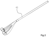
Fig. 2 zeigt eine schematische perspektivische Darstellung eines Führungsrohrs der Verbindungsvorrichtung (am unteren Ende nicht gebohrt). -
Fig. 3 zeigt eine schematische Explosionsansicht des Führungsrohrs der Verbindungsvorrichtung (am unteren Ende nicht gebohrt). -
Fig. 1 bis 3 zeigen eine Verbindungsvorrichtung zwischen einem Unterputzwasserkasten und einer Spültoilette, wobei die Verbindungsvorrichtung zum Verbinden des Unterputzwasserkastens mit der Spültoilette dient und für den Gebrauch in eine Wand eingebettet wird. Die Spültoilette sieht aus wie an eine Wand angebaut und verfügt über eine Spülleitung und eine Abwasserableitung. Die Spülleitung dient als die Zulaufleitung für Toilettenspülwasser, während die Abwasserableitung als Abflussleitung für Abwasser fungiert. Die Verbindungsvorrichtung umfasst einen Befestigungsrahmen 10, ein Spülrohr 20, ein Abwasserrohr 30 und ein Führungsrohr 40. - Der Befestigungsrahmen 10 weist zwei vertikale Säulen 12, die auf der linken Seite und auf der rechten Seite angeordnet sind, sowie eine Montageplatte 14 auf, über die die linke und die rechte Säule horizontal verbunden sind. Auf der Montageplatte 14 sind Montagebohrungen für eine Montage der Spültoilette ausgebildet. Die Montagebohrungen sind auf den beiden Seiten der Mittelachse A angeordnet, durch die der Befestigungsrahmen links und rechts halbiert wird. Die Montageplatte 14 liegt auf einer Höhe unterhalb einer Mittelachse, durch die der Befestigungsrahmen oben und unten halbiert ist.
- Das Spülrohr 20 dient zur Verbindung des Unterputzwasserkastens mit der Spülleitung der Spültoilette, wobei das obere Ende eine Eintrittsöffnung bildet und mit dem Unterputzwasserkasten verbunden ist. Das untere Ende stützt sich auf der Montageplatte 14 ab, wobei die Öffnung am unteren Ende als Austrittsöffnung fungiert und zur Verbindung mit der Spülleitung der Spültoilette nach vorne gerichtet ist. Bei dem vorliegenden Ausführungsbeispiel liegt das Spülrohr 20 auf der Mittelachse A und ist L-förmig ausgebildet.
- Das Abwasserrohr 30 wird zum Verbinden mit der Abwasserableitung der Spültoilette verwendet, wobei dessen oberes Ende als Eintrittsöffnung und dessen unteres Ende als Austrittsöffnung dient und wobei die Eintrittsöffnung des Abwasserrohrs unterhalb der Montageplatte 14 angeordnet ist. Bei dem vorliegenden Ausführungsbeispiel liegt das Abwasserrohr 30 auf der Mittelachse A und ist L-förmig ausgebildet.
- Das Führungsrohr 40 ist als Hohlrohr ausgebildet, dessen Innenraum für die Verlegung von Leitungen (beispielsweise Drähte) oder Wasserrohren vorgesehen ist, wobei das obere Ende des Führungsrohrs 40 mit dem Unterputzwasserkasten kommuniziert, und wobei das untere Ende des Führungsrohrs 40 unterhalb der Eintrittsöffnung des Abwasserrohrs 30 und abweichend von der Mittelachse A angeordnet ist. Da die induktive Betätigungsplatte zur Spülung auf der Oberseite des Unterputzwasserkastens vorgesehen ist, können die Wasserleitungen zur weiblichen und hinteren Reinigung der Spültoilette sowie die Datenkabel zur Steuerung der intelligenten Spülung durch das Führungsrohr 40 verlaufen.
- Vorzugsweise ist es vorgesehen, dass das obere Ende des Führungsrohrs 40 offen ausgebildet ist und eine Öffnung bildet, und dass das untere Ende geschlossen ausgebildet ist und zum Einbau von Kabel- oder Wasserleitungen gebohrt wird. Das untere Ende des Führungsrohrs 40 ist zunächst verschlossen, um Verstopfungen während Bauarbeiten zu verhindern.
- Vorzugsweise ist vorgesehen, dass das Bohrloch am unteren Ende des Führungsrohrs 40 als Einlass und die Öffnung am oberen Ende als Auslass verwendet wird. Die Kabel- oder Wasserleitungen werden also durch das untere Ende des Führungsrohrs 40 eingeführt und verlaufen dann in dem Innenraum des Führungsrohrs nach oben und können schließlich an den Unterputzwasserkasten angeschlossen werden. Da die Verlegung von Draht- und Rohrleitungen von unten erfolgt, werden die Bau- und Installationsarbeiten erleichtert.
- Erfindungsgemäß ist das Führungsrohr 40 unten gegabelt, um zwei untere Enden zu bilden, wie in der Zeichnung dargestellt. Die beiden unteren Enden werden getrennt gebohrt, und zwar eines für die Verdrahtung und das andere für die Rohrverlegung, um somit eine vereinfachte Anordnung zu erreichen.
- Erfindungsgemäß ist vorgesehen, dass das Führungsrohr 40 hinter der Montageplatte 14 angeordnet und nahe seinem unteren Ende nach vorne gebogen ist, so dass die untere Stirnfläche nach vorne gerichtet ist. Da sich das Führungsrohr auf der Rückseite der Montageplatte befindet, werden weder andere Bauteile beeinträchtigt, noch ist es erforderlich, die Dicke des Befestigungsrahmens zu vergrößern.
- Vorzugsweise besteht das Führungsrohr 40 aus zwei Teilen, nämlich einem geraden Rohrabschnitt 42 und einem gebogenen Rohrabschnitt 44, die beide miteinander in Steckverbindung stehen, wobei der gebogene Rohrabschnitt 44 an seinem unteren Abschnitt als V-förmige Verzweigung ausgebildet ist, so dass dort zwei untere Enden entstehen. Das Führungsrohr ist ein Kunststoffteil, das mit einer zweiteiligen Form die Herstellung erleichtert.
- Erfindungsgemäß umfasst der Befestigungsrahmen 10 ferner einen Verstärkungssteg 16, mit dem die linke und die rechte Säule horizontal miteinander verbunden sind. Der Verstärkungssteg 16 ist unterhalb der Eintrittsöffnung des Abwasserrohrs 30 angeordnet, wobei der nach vorne gebogene Abschnitt des Führungsrohrs 40 unterhalb des Verstärkungsstegs 16 eingerastet ist. Bei dem vorliegenden Ausführungsbeispiel ist das Führungsrohr 40 mit dem Verstärkungssteg 16 fest miteinander verbunden. Durch den Verstärkungssteg 16 wird nicht nur die Festigkeit des Befestigungsrahmens erhöht, sondern das Führungsrohr ferner in seiner Position gesichert und somit verhindert, dass es sich lockert.
- Vorzugsweise beträgt der Abstand zwischen dem unteren Endabschnitt des Führungsrohrs 40 und der Mittelachse A weniger als 190 mm. Der untere Endabschnitt des Führungsrohrs kann in einem Bereich, der sich von der Seite des Abwasserrohrs nach außen bis zu einer im Abstand von 190 mm zur Mittelachse befindlichen Stelle erstreckt, angeordnet werden, sodass große Arbeitsräume hinter der Toilette geschaffen werden und die Bauarbeiten erleichtern.
- Vorzugsweise ist die Höhe des unteren Endes des Führungsrohrs 40 geringer als die Höhe der Unterseite der am Befestigungsrahmen 10 montierten Spültoilette. Dies bedeutet, dass sich die Öffnung am unteren Ende des Führungsrohrs nach Einbau der Spültoilette unterhalb der Bodenfläche der Toilette befindet. Die Toilette verdeckt tatsächlich nicht die Öffnung am unteren Ende des Führungsrohrs, was es erleichtert, die Drähte und Rohrleitungen von unten zu verlegen.
- Die vorstehenden Ausführungen dienen nur als bevorzugte Ausführungsbeispiele der vorliegenden Erfindung.
Claims (7)
- Verbindungsvorrichtung zwischen einem Unterputzwasserkasten und einer Spültoilette, mit:einem Befestigungsrahmen (10), aufweisend zwei vertikal angeordnete Säulen (12), die links und rechts angeordnet sind;einer Montageplatte (14) zur horizontalen Verbindung der linken und der rechten Säule (12), wobei auf der Montageplatte (14) Montagebohrungen für eine Montage der Spültoilette vorgesehen sind;einem Spülrohr (20) zum Verbinden des Unterputzwasserkastens mit einer Spülleitung der Spültoilette;einem Abwasserrohr (30) zum Verbinden mit einer Abwasserableitung der Spültoilette, wobei sich eine Eintrittsöffnung des Abwasserrohrs (30) unterhalb der Montageplatte (14) befindet,einem Führungsrohr (40), das als Hohlrohr ausgebildet ist und dessen Innenraum für die Verlegung von Kabel- oder Wasserleitungen verwendet wird,wobei das obere Ende des Führungsrohrs (40) mit dem Unterputzwasserkasten kommuniziert,wobei das untere Ende des Führungsrohrs (40) abweichend von der Mittelachse (A) angeordnet ist, durch welche der Befestigungsrahmen (10) links und rechts halbiert wird,wobei das Führungsrohr (40) hinter der Montageplatte (14) angeordnet ist,wobei der Befestigungsrahmen (10) ferner einen Verstärkungssteg (16) aufweist, mit dem die linke und rechte Säule (12) horizontal miteinander verbunden sind, wobei der Verstärkungssteg (16) unterhalb der Eintrittsöffnung des Abwasserrohrs (30) angeordnet ist,wobei das Führungsrohr (40) unten gegabelt ist, um zwei untere Enden zu bilden, undwobei das Führungsrohr (40) nahe seinem unteren Ende nach vorne gebogen ist, so dass die untere Stirnfläche nach vorne gerichtet ist,dadurch gekennzeichnet,dass das untere Ende des Führungsrohrs (40) unterhalb der Eintrittsöffnung des Abwasserrohrs (30) angeordnet ist, unddass der nach vorne gebogene Abschnitt des Führungsrohrs (40) unterhalb des Verstärkungsstegs (16) eingerastet ist.
- Verbindungsvorrichtung zwischen einem Unterputzwasserkasten und einer Spültoilette nach Anspruch 1, dadurch gekennzeichnet, dass das obere Ende des Führungsrohrs (40) offen ausgebildet ist und eine Öffnung bildet, und dass das untere Ende geschlossen ausgebildet ist und beim Einbau von Kabel- oder Wasserleitungen gebohrt wird.
- Verbindungsvorrichtung zwischen einem Unterputzwasserkasten und einer Spültoilette nach Anspruch 2, dadurch gekennzeichnet, dass das Bohrloch am unteren Ende des Führungsrohrs (40) als Einlass und die Öffnung am oberen Ende als Auslass dienen, wobei die Kabel- oder Wasserleitungen durch das untere Ende des Führungsrohrs (40) eingeführt werden und dann in dem Innenraum des Führungsrohrs (40) nach oben verlaufen, und schließlich an den Unterputzwasserkasten angeschlossen werden können.
- Verbindungsvorrichtung zwischen einem Unterputzwasserkasten und einer Spültoilette nach Anspruch 1, dadurch gekennzeichnet, dass das Führungsrohr (40) zweiteilig ausgebildet ist und einen geraden Rohrabschnitt (42) und einen gebogenen Rohrabschnitt (44) aufweist, die miteinander in Steckverbindung stehen.
- Verbindungsvorrichtung zwischen einem Unterputzwasserkasten und einer Spültoilette nach Anspruch 1, dadurch gekennzeichnet, dass das Führungsrohr (40) mit dem Verstärkungssteg (16) fest verbunden ist.
- Verbindungsvorrichtung zwischen einem Unterputzwasserkasten und einer Spültoilette nach Anspruch 1, dadurch gekennzeichnet, dass der Abstand zwischen dem unteren Ende des Führungsrohrs (40) und der Mittelachse (A) maximal 190 mm beträgt.
- Verbindungsvorrichtung zwischen einem Unterputzwasserkasten und einer Spültoilette nach Anspruch 1 oder 6, mit einer eingebauten Spültoilette, dadurch gekennzeichnet, dass die Höhe des unteren Endes des Führungsrohrs (40) niedriger ist als die Höhe der Unterseite der am Befestigungsrahmen (10) montierten Spültoilette.
Applications Claiming Priority (1)
| Application Number | Priority Date | Filing Date | Title |
|---|---|---|---|
| CN202021536839.4U CN213296561U (zh) | 2020-07-29 | 2020-07-29 | 隐藏式水箱与冲洗式坐便器的连接装置 |
Publications (3)
| Publication Number | Publication Date |
|---|---|
| EP3957801A1 EP3957801A1 (de) | 2022-02-23 |
| EP3957801C0 EP3957801C0 (de) | 2025-01-29 |
| EP3957801B1 true EP3957801B1 (de) | 2025-01-29 |
Family
ID=76022189
Family Applications (1)
| Application Number | Title | Priority Date | Filing Date |
|---|---|---|---|
| EP21188264.2A Active EP3957801B1 (de) | 2020-07-29 | 2021-07-28 | Verbindungsvorrichtung zwischen einem unterputzwasserkasten und einer spüle |
Country Status (2)
| Country | Link |
|---|---|
| EP (1) | EP3957801B1 (de) |
| CN (1) | CN213296561U (de) |
Family Cites Families (3)
| Publication number | Priority date | Publication date | Assignee | Title |
|---|---|---|---|---|
| DK2568089T3 (da) * | 2011-09-12 | 2020-02-10 | Geberit Int Ag | Anvendelse af en toilettilslutningsanordning og et brusetoilet |
| DE102013203941A1 (de) * | 2013-03-07 | 2014-09-11 | Tece Gmbh | Leitungsführungseinrichtung für einen Installationsblock und Installationsblock mit Leitungsführungseinrichtung |
| CN108374466B (zh) * | 2017-01-30 | 2020-07-14 | Toto株式会社 | 壁挂式便器用安装装置以及冲厕系统 |
-
2020
- 2020-07-29 CN CN202021536839.4U patent/CN213296561U/zh active Active
-
2021
- 2021-07-28 EP EP21188264.2A patent/EP3957801B1/de active Active
Also Published As
| Publication number | Publication date |
|---|---|
| EP3957801A1 (de) | 2022-02-23 |
| CN213296561U (zh) | 2021-05-28 |
| EP3957801C0 (de) | 2025-01-29 |
Similar Documents
| Publication | Publication Date | Title |
|---|---|---|
| EP2154297B1 (de) | Brauseanordnung | |
| EP2568089B1 (de) | Verwendung einer WC-Anschlussvorrichtung und eines Dusch-WCs | |
| EP2217766B1 (de) | Spülwassereinrichtung für ein toilettenbecken | |
| EP3470587B1 (de) | Vorrichtung zur befestigung eines wcs an einer wand und wc-anordnung mit einer entsprechenden vorrichtung | |
| EP1862602B1 (de) | Becken mit verdecktem Überlauf und zugehöriger Ablaufgarnitur | |
| DE102020004384A1 (de) | Bauschutz und Vorwandelement mit Bauschutz | |
| EP3957801A1 (de) | Verbindungsvorrichtung zwischen einem unterputzwasserkasten und einer spüle | |
| EP1605109A1 (de) | Klosettschüssel für ein WC | |
| DE3447098C1 (de) | Unterputz-Siphon | |
| DE3310314C2 (de) | ||
| EP4036326B1 (de) | Sanitäres system sowie verfahren zur herstellung und betrieb desselbigen | |
| EP3775415B1 (de) | Ablaufanordnung für einen waschtisch | |
| DE102018133514A1 (de) | WC-Anschlussvorrichtung zum wandseitigen Anschluss eines Dusch-WC und Verfahren zur Installation eines Dusch-WC unter Verwendung einer WC-Anschlussvorrichtung | |
| EP1267005A2 (de) | Ablaufgarnitur für ein Becken oder eine Wanne | |
| EP2182124B1 (de) | Spülvorrichtung mit einer Ventilanordnung | |
| EP0916775B1 (de) | Kastenkörper für einen Spülkasten | |
| DE1659021A1 (de) | Vorgefertigtes Bauelement,vorzugsweise fuer den nassen Teil eines Gebaeudes | |
| EP2101001A2 (de) | Einbaukasten mit schlauchgeführten Anschlüssen für eine Sanitärarmatur | |
| EP0577620A1 (de) | Durchflussdrossel. | |
| EP0557750B1 (de) | Ablaufarmatur einer wandhängenden Toilette | |
| EP2072695B2 (de) | Unterputzspülkasten mit einem Anschlussstück zum Anschliessen einer Wasserversorgungsleitung und Verfahren zum Anschliessen eines Unterputzspülkastens an eine Wasserversorgungsleitung | |
| DE202015001752U1 (de) | Spüleinheit | |
| DE2848498A1 (de) | Inspektionskammer-anordnung | |
| DE19510228A1 (de) | Befestigungsvorrichtung eines Spülkastens | |
| EP1662051B1 (de) | Verfahren zum Verbinden eines öffentlichen Verteilerschachtes mit einem Hausanschluss |
Legal Events
| Date | Code | Title | Description |
|---|---|---|---|
| PUAI | Public reference made under article 153(3) epc to a published international application that has entered the european phase |
Free format text: ORIGINAL CODE: 0009012 |
|
| STAA | Information on the status of an ep patent application or granted ep patent |
Free format text: STATUS: THE APPLICATION HAS BEEN PUBLISHED |
|
| AK | Designated contracting states |
Kind code of ref document: A1 Designated state(s): AL AT BE BG CH CY CZ DE DK EE ES FI FR GB GR HR HU IE IS IT LI LT LU LV MC MK MT NL NO PL PT RO RS SE SI SK SM TR |
|
| STAA | Information on the status of an ep patent application or granted ep patent |
Free format text: STATUS: REQUEST FOR EXAMINATION WAS MADE |
|
| 17P | Request for examination filed |
Effective date: 20220823 |
|
| RBV | Designated contracting states (corrected) |
Designated state(s): AL AT BE BG CH CY CZ DE DK EE ES FI FR GB GR HR HU IE IS IT LI LT LU LV MC MK MT NL NO PL PT RO RS SE SI SK SM TR |
|
| GRAP | Despatch of communication of intention to grant a patent |
Free format text: ORIGINAL CODE: EPIDOSNIGR1 |
|
| STAA | Information on the status of an ep patent application or granted ep patent |
Free format text: STATUS: GRANT OF PATENT IS INTENDED |
|
| RIC1 | Information provided on ipc code assigned before grant |
Ipc: E03D 9/08 20060101ALN20240418BHEP Ipc: H02G 3/38 20060101ALN20240418BHEP Ipc: H02G 3/04 20060101ALN20240418BHEP Ipc: E03D 11/13 20060101ALI20240418BHEP Ipc: E03D 11/14 20060101AFI20240418BHEP |
|
| RIC1 | Information provided on ipc code assigned before grant |
Ipc: E03D 9/08 20060101ALN20240425BHEP Ipc: H02G 3/38 20060101ALN20240425BHEP Ipc: H02G 3/04 20060101ALN20240425BHEP Ipc: E03D 11/13 20060101ALI20240425BHEP Ipc: E03D 11/14 20060101AFI20240425BHEP |
|
| INTG | Intention to grant announced |
Effective date: 20240508 |
|
| RIN1 | Information on inventor provided before grant (corrected) |
Inventor name: YU, XINGYI Inventor name: PENG, DONG Inventor name: CHEN, GANMING |
|
| GRAJ | Information related to disapproval of communication of intention to grant by the applicant or resumption of examination proceedings by the epo deleted |
Free format text: ORIGINAL CODE: EPIDOSDIGR1 |
|
| STAA | Information on the status of an ep patent application or granted ep patent |
Free format text: STATUS: REQUEST FOR EXAMINATION WAS MADE |
|
| INTC | Intention to grant announced (deleted) | ||
| GRAP | Despatch of communication of intention to grant a patent |
Free format text: ORIGINAL CODE: EPIDOSNIGR1 |
|
| STAA | Information on the status of an ep patent application or granted ep patent |
Free format text: STATUS: GRANT OF PATENT IS INTENDED |
|
| RIC1 | Information provided on ipc code assigned before grant |
Ipc: E03D 9/08 20060101ALN20240904BHEP Ipc: H02G 3/38 20060101ALN20240904BHEP Ipc: H02G 3/04 20060101ALN20240904BHEP Ipc: E03D 11/13 20060101ALI20240904BHEP Ipc: E03D 11/14 20060101AFI20240904BHEP |
|
| INTG | Intention to grant announced |
Effective date: 20240913 |
|
| GRAS | Grant fee paid |
Free format text: ORIGINAL CODE: EPIDOSNIGR3 |
|
| GRAA | (expected) grant |
Free format text: ORIGINAL CODE: 0009210 |
|
| STAA | Information on the status of an ep patent application or granted ep patent |
Free format text: STATUS: THE PATENT HAS BEEN GRANTED |
|
| AK | Designated contracting states |
Kind code of ref document: B1 Designated state(s): AL AT BE BG CH CY CZ DE DK EE ES FI FR GB GR HR HU IE IS IT LI LT LU LV MC MK MT NL NO PL PT RO RS SE SI SK SM TR |
|
| REG | Reference to a national code |
Ref country code: GB Ref legal event code: FG4D Free format text: NOT ENGLISH |
|
| REG | Reference to a national code |
Ref country code: CH Ref legal event code: EP |
|
| REG | Reference to a national code |
Ref country code: DE Ref legal event code: R096 Ref document number: 502021006490 Country of ref document: DE |
|
| REG | Reference to a national code |
Ref country code: IE Ref legal event code: FG4D Free format text: LANGUAGE OF EP DOCUMENT: GERMAN |
|
| U01 | Request for unitary effect filed |
Effective date: 20250224 |
|
| U07 | Unitary effect registered |
Designated state(s): AT BE BG DE DK EE FI FR IT LT LU LV MT NL PT RO SE SI Effective date: 20250303 |
|
| PG25 | Lapsed in a contracting state [announced via postgrant information from national office to epo] |
Ref country code: RS Free format text: LAPSE BECAUSE OF FAILURE TO SUBMIT A TRANSLATION OF THE DESCRIPTION OR TO PAY THE FEE WITHIN THE PRESCRIBED TIME-LIMIT Effective date: 20250429 |
|
| PG25 | Lapsed in a contracting state [announced via postgrant information from national office to epo] |
Ref country code: PL Free format text: LAPSE BECAUSE OF FAILURE TO SUBMIT A TRANSLATION OF THE DESCRIPTION OR TO PAY THE FEE WITHIN THE PRESCRIBED TIME-LIMIT Effective date: 20250129 |
|
| PG25 | Lapsed in a contracting state [announced via postgrant information from national office to epo] |
Ref country code: ES Free format text: LAPSE BECAUSE OF FAILURE TO SUBMIT A TRANSLATION OF THE DESCRIPTION OR TO PAY THE FEE WITHIN THE PRESCRIBED TIME-LIMIT Effective date: 20250129 |
|
| PG25 | Lapsed in a contracting state [announced via postgrant information from national office to epo] |
Ref country code: NO Free format text: LAPSE BECAUSE OF FAILURE TO SUBMIT A TRANSLATION OF THE DESCRIPTION OR TO PAY THE FEE WITHIN THE PRESCRIBED TIME-LIMIT Effective date: 20250429 Ref country code: IS Free format text: LAPSE BECAUSE OF FAILURE TO SUBMIT A TRANSLATION OF THE DESCRIPTION OR TO PAY THE FEE WITHIN THE PRESCRIBED TIME-LIMIT Effective date: 20250529 |
|
| PG25 | Lapsed in a contracting state [announced via postgrant information from national office to epo] |
Ref country code: HR Free format text: LAPSE BECAUSE OF FAILURE TO SUBMIT A TRANSLATION OF THE DESCRIPTION OR TO PAY THE FEE WITHIN THE PRESCRIBED TIME-LIMIT Effective date: 20250129 |
|
| PG25 | Lapsed in a contracting state [announced via postgrant information from national office to epo] |
Ref country code: GR Free format text: LAPSE BECAUSE OF FAILURE TO SUBMIT A TRANSLATION OF THE DESCRIPTION OR TO PAY THE FEE WITHIN THE PRESCRIBED TIME-LIMIT Effective date: 20250430 |
|
| U20 | Renewal fee for the european patent with unitary effect paid |
Year of fee payment: 5 Effective date: 20250707 |
|
| PG25 | Lapsed in a contracting state [announced via postgrant information from national office to epo] |
Ref country code: SM Free format text: LAPSE BECAUSE OF FAILURE TO SUBMIT A TRANSLATION OF THE DESCRIPTION OR TO PAY THE FEE WITHIN THE PRESCRIBED TIME-LIMIT Effective date: 20250129 |
|
| PGFP | Annual fee paid to national office [announced via postgrant information from national office to epo] |
Ref country code: GB Payment date: 20250722 Year of fee payment: 5 |
|
| PG25 | Lapsed in a contracting state [announced via postgrant information from national office to epo] |
Ref country code: CZ Free format text: LAPSE BECAUSE OF FAILURE TO SUBMIT A TRANSLATION OF THE DESCRIPTION OR TO PAY THE FEE WITHIN THE PRESCRIBED TIME-LIMIT Effective date: 20250129 |
|
| PG25 | Lapsed in a contracting state [announced via postgrant information from national office to epo] |
Ref country code: SK Free format text: LAPSE BECAUSE OF FAILURE TO SUBMIT A TRANSLATION OF THE DESCRIPTION OR TO PAY THE FEE WITHIN THE PRESCRIBED TIME-LIMIT Effective date: 20250129 |
|
| PLBE | No opposition filed within time limit |
Free format text: ORIGINAL CODE: 0009261 |
|
| STAA | Information on the status of an ep patent application or granted ep patent |
Free format text: STATUS: NO OPPOSITION FILED WITHIN TIME LIMIT |
|
| REG | Reference to a national code |
Ref country code: CH Ref legal event code: L10 Free format text: ST27 STATUS EVENT CODE: U-0-0-L10-L00 (AS PROVIDED BY THE NATIONAL OFFICE) Effective date: 20251210 |
|
| 26N | No opposition filed |
Effective date: 20251030 |
|
| REG | Reference to a national code |
Ref country code: CH Ref legal event code: H13 Free format text: ST27 STATUS EVENT CODE: U-0-0-H10-H13 (AS PROVIDED BY THE NATIONAL OFFICE) Effective date: 20260224 |
|
| PG25 | Lapsed in a contracting state [announced via postgrant information from national office to epo] |
Ref country code: CH Free format text: LAPSE BECAUSE OF NON-PAYMENT OF DUE FEES Effective date: 20250731 |