EP3470587B1 - Vorrichtung zur befestigung eines wcs an einer wand und wc-anordnung mit einer entsprechenden vorrichtung - Google Patents
Vorrichtung zur befestigung eines wcs an einer wand und wc-anordnung mit einer entsprechenden vorrichtung Download PDFInfo
- Publication number
- EP3470587B1 EP3470587B1 EP18000754.4A EP18000754A EP3470587B1 EP 3470587 B1 EP3470587 B1 EP 3470587B1 EP 18000754 A EP18000754 A EP 18000754A EP 3470587 B1 EP3470587 B1 EP 3470587B1
- Authority
- EP
- European Patent Office
- Prior art keywords
- toilet
- mounting
- fastening
- connection box
- cover
- Prior art date
- Legal status (The legal status is an assumption and is not a legal conclusion. Google has not performed a legal analysis and makes no representation as to the accuracy of the status listed.)
- Active
Links
Images

Classifications
-
- E—FIXED CONSTRUCTIONS
- E03—WATER SUPPLY; SEWERAGE
- E03D—WATER-CLOSETS OR URINALS WITH FLUSHING DEVICES; FLUSHING VALVES THEREFOR
- E03D11/00—Other component parts of water-closets, e.g. noise-reducing means in the flushing system, flushing pipes mounted in the bowl, seals for the bowl outlet, devices preventing overflow of the bowl contents; devices forming a water seal in the bowl after flushing, devices eliminating obstructions in the bowl outlet or preventing backflow of water and excrements from the waterpipe
- E03D11/13—Parts or details of bowls; Special adaptations of pipe joints or couplings for use with bowls, e.g. provisions in bowl construction preventing backflow of waste-water from the bowl in the flushing pipe or cistern, provisions for a secondary flushing, for noise-reducing
- E03D11/14—Means for connecting the bowl to the wall, e.g. to a wall outlet
- E03D11/143—Mounting frames for toilets and urinals
- E03D11/146—Mounting frames for toilets and urinals with incorporated cistern
Definitions
- the present invention relates to a device for attaching a toilet to a wall and to a toilet assembly with a corresponding device.
- Such devices allow toilets and cisterns for holding a flushing liquid for the toilet to be securely attached to the wall.
- Devices for attaching a toilet are known, for example, from the publications DE102015111423A1 , EP1703030A2 and DE102013203941A1 .
- Known devices for attaching toilets have a mounting frame to which the toilet and cistern can be attached using a variety of fasteners such as threaded rods, screws and/or nuts.
- shower toilets with an additional bidet function are also known.
- Such shower toilets can include motor-driven shower arms, by means of which a shower jet can be directed onto a user's lower abdomen.
- the shower arms usually require an additional shower water line and/or electrical connection cables for a drive motor of the shower arm.
- the arrangement of corresponding water connections and/or power connections on known devices for attaching toilets to a wall has proven difficult because there is often insufficient installation space. Furthermore, such devices often require a high level of assembly work.
- the object of the invention is therefore to at least partially solve the problems described with reference to the prior art and, in particular, to provide a device with which toilets can be attached to a wall with minimal installation effort. Furthermore, a toilet assembly is to be proposed that enables a toilet to be attached to a wall with minimal installation effort.
- a device for fastening a toilet to a wall contributes to this, which device has a fastening frame with at least one fastening cross member, wherein the fastening cross member comprises a fastening surface to which the toilet can be fastened by means of at least one fastening element, wherein the fastening surface of the device is arranged in such a way that an assembly space can be formed between the fastening surface and a cover of the device or between the fastening surface and the toilet.
- the device is used to attach a toilet to a wall.
- toilets can be attached in particular to lightweight walls that are not suitable for direct attachment of the toilet bowl.
- the device can be used to attach a cistern for containing flushing liquid for the toilet to the wall.
- the device has a fastening frame that comprises in particular a plurality of metal profiles.
- the fastening frame can, for example, have a first vertical metal profile and a second vertical metal profile, which are connected to one another via a (horizontal) upper first cross member and a (horizontal) lower second cross member.
- the fastening frame can have feet by means of which the height of the fastening frame can be adjusted.
- the mounting frame has at least one mounting cross member with a mounting surface to which the toilet can be attached by means of at least one fastening element.
- the mounting cross member is preferably made at least partially of metal, in particular sheet metal. with a thickness of 1 mm to 5 mm, preferably (essentially) 2 mm.
- the fastening cross member is preferably arranged (horizontally) between the first vertical metal profile and the second vertical metal profile of the fastening frame. Furthermore, the fastening cross member can be fastened to the fastening frame in a force-fitting and/or form-fitting manner.
- the fastening surface of the fastening cross member is an area of the fastening cross member in which at least one bore or threaded hole is arranged for the at least one fastening element of the toilet. After the device has been fastened to the wall, the fastening surface preferably runs (essentially) parallel to the wall.
- the at least one fastening element is, for example, a threaded rod, a fastening bolt, or a screw.
- the at least one fastening element can be screwed into the at least one bore or threaded hole in the fastening surface of the fastening cross member and/or fastened by means of at least one nut.
- the toilet can thus be mounted to the fastening cross member of the device by means of the at least one fastening element.
- the fastening surface of the fastening cross member is arranged in such a way that an installation space can be formed between the fastening surface and a cover of the device or between the fastening surface and the toilet.
- the cover can, for example, be at least one plate and/or tile that (invisibly) conceals the device when installed.
- the installation space thus created can, in particular, be used for at least one electrical connection cable and/or a flush water line of a shower toilet, thereby reducing the installation effort for such toilets.
- the installation space preferably comprises a volume of at least 100 cubic centimeters and can, for example, be in the range of 600 to 3,000 cubic centimeters.
- the fastening surface can be set back from a front side of the fastening frame. This means that the fastening surface is not flush with the front side of the fastening frame.
- the front side of the fastening frame is in particular a surface that is spanned by those surfaces of the metal profiles and/or cross members that point away from the wall when the device is installed.
- the fastening surface is offset towards the wall relative to the front side of the fastening frame.
- the offset between the front side and the fastening surface can be, for example, 10 mm (millimeters) to 100 mm. This creates the mounting space in the fastening frame, in particular between the first vertical metal profile and the second vertical metal profile, which, when the device is installed, is located between the fastening surface and the cover of the device or between the fastening surface and the toilet.
- the mounting cross-piece may have a U-shaped cross-section.
- the cross-section of the mounting cross-piece may be hat-shaped.
- the mounting cross member can have at least one contact surface for a cover of the device, wherein the mounting surface and the at least one contact surface are spaced apart from one another.
- the at least one contact surface of the mounting cross member runs in particular parallel to the mounting surface of the mounting cross member and/or parallel to the front side of the mounting frame.
- the distance (horizontal when the device is in the assembled state) between the mounting surface and the at least one contact surface can be, for example, 10 mm (millimeters) to 100 mm.
- the device further comprises a junction box with at least one interior space for an electricity-conducting element, wherein the at least one interior space can be sealed liquid-tight from the environment.
- the junction box is made, in particular, at least partially of plastic and/or metal.
- At least one electricity-conducting element such as an electrical connection cable, a plug for an electrical connection cable, or a transformer, can be arranged in the at least one interior space.
- a fan can also be arranged in the at least one interior space.
- the at least one interior space Before the installation of a toilet, the at least one interior space can be open in at least one direction. The opening of the at least one interior space can be closed by the toilet after its installation, so that the at least one interior space is sealed from the environment.
- the at least one interior space can have further openings through which connection cables, for example electrical connection cables and/or water pipes, can be guided. These openings can have seals so that no liquids can enter the at least one interior space through these openings either.
- connection cables for example electrical connection cables and/or water pipes
- connection box can have a T-shaped base.
- connection box is attached to the mounting crossbar. If the connection box has a T-shaped base, the connection box is attached to the mounting crossbar, particularly with its horizontal section.
- the attachment can be achieved, for example, via a screw connection and/or with at least one fastening element for the toilet.
- a toilet flush water pipe, a toilet waste water pipe, a toilet shower water pipe or an electrical connection cable of the toilet can be routed through the connection box.
- junction box can extend through a cover of the device and be connected to the cover in a fluid-tight manner.
- a seal made of silicone, for example, can be provided between the junction box and the cover.
- a toilet arrangement which comprises a device described here for fastening a toilet to a wall and a toilet, wherein the toilet is fastened by means of at least one fastening element to a fastening surface of a fastening cross member of the device and wherein an assembly space is formed between the fastening surface and a cover of the device or between the fastening surface and the toilet.
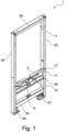
- the Fig. 1 shows the device 1 with a fastening frame 4 in a perspective view.
- the fastening frame 4 comprises a first vertical metal profile 25 and a second vertical metal profile 26, which are connected to one another by an upper first crossbeam 29 and a lower second crossbeam 30.
- the first vertical metal profile 25 has a telescopic first foot 27 at one longitudinal end and the second vertical metal profile 26 has a telescopic second foot 28 at one longitudinal end, by means of which a height of the fastening frame 4 can be adjusted during assembly of the device 1.
- the fastening cross member 5 has a fastening surface 6 that is set back from a front side 11 of the fastening frame 4, so that a mounting space 10 is formed between the first vertical metal profile 25 and the second vertical metal profile 26.
- the fastening cross member 5 also has a first contact surface 13 and a second contact surface 36 that run parallel or flush with the front side 11 of the fastening frame 4.
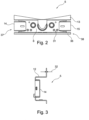
- the Fig. 2 shows the fastening cross member 5 in a front view.
- the fastening surface 6 has two holes 31 on the left and right, to which fastening elements 7, 8 (not shown here) for a toilet 2 can be fastened.
- the fastening surface 6 has a first bead 14 at a first longitudinal end 37 and a second bead 15 at a second longitudinal end 38.
- Fig. 2 the first contact surface 13 and the second contact surface 36 can be seen.
- the Fig. 3 shows the fastening cross member 5 in a side view with a view of the first bead 14. It can be seen here that the fastening cross member 5 has a U-shaped or hat-shaped cross section 12.
- the fastening cross member 5 is also made of a formed metal sheet with a thickness of 32.
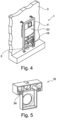
- the Fig. 4 shows the device 1 after the mounting frame 4 has been attached to a wall 3.
- a cistern 33 for flushing liquid from a toilet 2 (not shown here) was also arranged on the mounting frame 4, and a connection box 16 was arranged on the mounting cross member 5.
- the Fig. 5 shows the connection box 16 in a perspective view.
- the connection box 16 has two openings 34 on the left and right sides, which, when installed, are connected to the Fig. 2 shown holes 31 of the fastening surface 6 of the fastening cross member 5 are aligned.
- the connection box 16 can therefore be fastened to the fastening cross member 5 by means of the fastening elements 7, 8 not shown here.
- the connection box 16 shown here has a T-shaped base area.
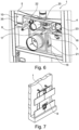
- the Fig. 6 shows a detailed view of the Fig. 4 shown device 1 in the area of the connection box 16 in a perspective view.
- the connection box 16 is fastened with a first fastening element 7 and a second fastening element 8 with its horizontal section in the mounting space 10 of the fastening cross member 5.
- the connection box 16 has a first interior space 17, in which an electricity-carrying element 18 in the manner of a transformer for a (shower) toilet 2 (not shown here) is arranged and into which an electrical connection line 23 opens.
- the connection box 16 has a second interior space 35, into which a shower water line 22 for a (shower) toilet 2 (not shown here) opens.
- a flush water line 20 extends, by means of which flush water is conveyed from the Fig. 4 shown cistern 33 to the WC 2, and a waste water line 21, with which waste water from the WC 2 can be conducted, for example, into a public sewer system, through the connection box 16.
- the flush water line 20 and the waste water line 21 are held on the mounting frame 4 by the connection box 16.
- the flush water line 20 extends through the horizontal area of the connection box 16 and the waste water line 21 through a vertical area of the connection box 16.
- the Fig. 7 shows the device 1 after it has been covered by a cover 9.
- the Fig. 8 shows a WC arrangement 24 with a device 1 covered by the cover 9 and therefore not visible and a WC 2.
- the WC 2 covers the Fig. 6 shown first interior space 17 and second interior space 35, wherein a seal 39, for example in the form of silicone, is formed between the toilet 2 and the cover 9, so that the first interior space 17 and the second interior space 35 are sealed in a liquid-tight manner with respect to an environment 19. This prevents liquid from entering the first interior space 17 and the second interior space 35 when the toilet 2 is cleaned, for example with a high-pressure cleaner, as is not uncommon in public toilets.
- a seal 39 for example in the form of silicone
- a (shower) toilet can be attached to a wall with little effort.
Landscapes
- Health & Medical Sciences (AREA)
- Life Sciences & Earth Sciences (AREA)
- Engineering & Computer Science (AREA)
- Hydrology & Water Resources (AREA)
- Public Health (AREA)
- Water Supply & Treatment (AREA)
- Residential Or Office Buildings (AREA)
Description
- Die vorliegende Erfindung betrifft eine Vorrichtung zur Befestigung eines WCs an einer Wand sowie eine WC-Anordnung mit einer entsprechenden Vorrichtung. Mit solchen Vorrichtungen sind WCs und Spülkästen zur Aufnahme einer Spülflüssigkeit für das WC an der Wand sicher befestigbar. Vorrichtungen zur Befestigung eines WCs sind beispielsweise bekannt aus den Druckschriften
DE102015111423A1 ,EP1703030A2 undDE102013203941A1 . - Bekannte Vorrichtungen zur Befestigung von WCs weisen einen Befestigungsrahmen auf, an dem das WC und der Spülkasten mit einer Vielzahl von Befestigungsmitteln wie Gewindestangen, Schrauben und/oder Muttern befestigbar sind. Neben üblichen WCs sind auch sogenannte Dusch-WCs mit einer zusätzlichen Bidetfunktion bekannt. Solche Dusch-WCs können motorisch verfahrbare Duscharme umfassen, mittels denen ein Duschstrahl auf einen Unterleib eines Benutzers gerichtet werden kann. Für die Duscharme sind regelmäßig eine zusätzliche Duschwasserleitung und/oder elektrische Anschlussleitungen für einen Antriebsmotor des Duscharms erforderlich. Die Anordnung entsprechender Wasseranschlüsse und/oder Stromanschlüsse an bekannten Vorrichtungen zur Befestigung von WCs an einer Wand hat sich jedoch als schwierig herausgestellt, weil bei diesen häufig kein ausreichender Bauraum zur Verfügung steht. Weiterhin weisen solche Vorrichtungen häufig einen hohen Montageaufwand auf.
- Aufgabe der Erfindung ist es daher, die mit Bezug auf den Stand der Technik geschilderten Probleme zumindest teilweise zu lösen und insbesondere eine Vorrichtung anzugeben, mit der WCs mit geringerem Montageaufwand an einer Wand befestigbar sind. Weiterhin soll auch eine WC-Anordnung vorgeschlagen werden, die eine Befestigung eines WCs mit geringem Montageaufwand an einer Wand ermöglicht.
- Diese Aufgaben werden gelöst mit einer Vorrichtung und einer WC-Anordnung gemäß den Merkmalen der unabhängigen Patentansprüche. Weitere vorteilhafte Ausgestaltungen der Erfindung sind in den abhängigen Patentansprüchen angegeben. Es ist darauf hinzuweisen, dass die in den Patentansprüchen einzeln aufgeführten Merkmale in beliebiger technologisch sinnvoller Weise miteinander kombiniert werden können und weitere Ausgestaltungen der Erfindung definieren. Darüber hinaus werden die in den Patentansprüchen angegebenen Merkmale in der Beschreibung näher präzisiert und erläutert, wobei weitere bevorzugte Ausgestaltungen der Erfindung dargestellt werden.
- Hierzu trägt eine Vorrichtung zur Befestigung eines WCs an einer Wand bei, die einen Befestigungsrahmen mit zumindest einer Befestigungstraverse aufweist, wobei die Befestigungstraverse eine Befestigungsfläche umfasst, an die das WC mittels zumindest einem Befestigungselement befestigbar ist, wobei die Befestigungsfläche der Vorrichtung derart angeordnet ist, dass zwischen der Befestigungsfläche und einer Abdeckung der Vorrichtung oder zwischen der Befestigungsfläche und dem WC ein Montageraum ausbildbar ist.
- Die Vorrichtung dient der Befestigung eines WCs an einer Wand. Mittels solcher Vorrichtungen können WCs insbesondere an Leichtbauwänden befestigt werden, die für eine direkte Befestigung des Toilettenbeckens nicht geeignet sind. Weiterhin kann die Vorrichtung der Befestigung eines Spülkastens zur Aufnahme einer Spülflüssigkeit für das WC an der Wand dienen. Hierzu weist die Vorrichtung einen Befestigungsrahmen auf, der insbesondere eine Mehrzahl von Metallprofile umfasst. Der Befestigungsrahmen kann beispielsweise ein erstes senkrechtes Metallprofil und ein zweites senkrechtes Metallprofil aufweisen, die über eine (waagerechte) obere erste Quertraverse und eine (waagerechte) untere zweite Quertraverse miteinander verbunden sind. Weiterhin kann der Befestigungsrahmen Füße aufweisen, mittels denen eine Höhe des Befestigungsrahmens einstellbar sind.
- Weiterhin weist der Befestigungsrahmen zumindest eine Befestigungstraverse mit einer Befestigungsfläche auf, an die das WC mittels zumindest einem Befestigungselement befestigbar ist. Die Befestigungstraverse besteht bevorzugt zumindest teilweise aus Metall, insbesondere Metallblech mit einer Stärke von 1 mm bis 5 mm, bevorzugt (im Wesentlichen) 2 mm. Die Befestigungstraverse ist bevorzugt (waagerecht) zwischen dem ersten senkrechten Metallprofil und dem zweiten senkrechten Metallprofil des Befestigungsrahmens angeordnet. Weiterhin kann die Befestigungstraverse kraftschlüssig und/oder formschlüssig an dem Befestigungsrahmen befestigt sein. Bei der Befestigungsfläche der Befestigungstraverse handelt es sich um einen Bereich der Befestigungstraverse, in dem zumindest eine Bohrung oder Gewindebohrung für das zumindest eine Befestigungselement des WCs angeordnet ist. Die Befestigungsfläche verläuft nach der Befestigung der Vorrichtung an der Wand bevorzugt (im Wesentlichen) parallel zu der Wand. Bei dem zumindest einen Befestigungselement handelt es sich beispielsweise um eine Gewindestange, einen Befestigungsbolzen oder eine Schraube. Das zumindest eine Befestigungselement ist in die zumindest eine Bohrung oder Gewindebohrung der Befestigungsfläche der Befestigungstraverse beispielsweise einschraubbar und/oder mittels zumindest einer Mutter befestigbar. Das WC ist somit mittels dem zumindest einen Befestigungselement an der Befestigungstraverse der Vorrichtung montierbar.
- Die Befestigungsfläche der Befestigungstraverse ist derart angeordnet, dass zwischen der Befestigungsfläche und einer Abdeckung der Vorrichtung oder zwischen der Befestigungsfläche und dem WC ein Montageraum ausbildbar ist. Bei der Abdeckung kann es sich beispielsweise um zumindest eine Platte und/oder Fliese handeln, die die Vorrichtung im montierten Zustand (unsichtbar) verdecken. Zwischen der Befestigungsfläche und der Abdeckung bzw. dem WC besteht im montierten Zustand der Vorrichtung somit bevorzugt kein direkter Kontakt. Der so gewonnene Montageraum kann insbesondere für zumindest eine elektrische Anschlussleitung und/oder eine Spülwasserleitung eines Dusch-WCs verwendet werden, wodurch sich der Montageaufwand solcher WCs reduziert. Der Montageraum umfasst bevorzugt ein Raumvolumen von zumindest 100 Kubikzentimeter und kann zum Beispiel im Bereich von 600 bis 3.000 Kubikzentimeter liegen.
- Die Befestigungsfläche kann gegenüber einer Frontseite des Befestigungsrahmens zurückversetzt sein. Dies bedeutet, dass die Befestigungsfläche nicht bündig zu der Frontseite des Befestigungsrahmens verläuft. Bei der Frontseite des Befestigungsrahmens handelt es sich insbesondere um eine Fläche, die durch diejenigen Oberflächen der Metallprofile und/oder Quertraversen aufgespannt wird, die im montierten Zustand der Vorrichtung von der Wand wegweisen. Die Befestigungsfläche ist im montierten Zustand der Vorrichtung relativ zu der Frontseite des Befestigungsrahmens in Richtung der Wand versetzt. Der Versatz zwischen der Frontseite und der Befestigungsfläche kann beispielsweise 10 mm (Millimeter) bis 100 mm aufweisen. Hierdurch wird in dem Befestigungsrahmen, insbesondere zwischen dem ersten senkrechten Metallprofil und dem zweiten senkrechten Metallprofil, der Montageraum ausgebildet, der sich im montierten Zustand der Vorrichtung zwischen der Befestigungsfläche und der Abdeckung der Vorrichtung oder zwischen der Befestigungsfläche und dem WC befindet.
- Die Befestigungstraverse kann einen U-förmigen Querschnitt aufweisen. Der Querschnitt der Befestigungstraverse kann hutförmig ausgebildet sein.
- Die Befestigungstraverse kann zumindest eine Anlagefläche für eine Abdeckung der Vorrichtung aufweisen, wobei die Befestigungsfläche und die zumindest eine Anlagefläche beabstandet zueinander ausgebildet sind. Die zumindest eine Anlagefläche der Befestigungstraverse verläuft insbesondere parallel zu der Befestigungsfläche der Befestigungstraverse und/oder parallel zu der Frontseite des Befestigungsrahmens. Der (im montierten Zustand der Vorrichtung horizontale) Abstand zwischen der Befestigungsfläche und der zumindest einen Anlagefläche kann beispielsweise 10 mm (Millimeter) bis 100 mm betragen.
- Die Befestigungstraverse kann zumindest eine Sicke aufweisen. Bevorzugt weist die Befestigungstraverse an ihrem ersten längsseitigen Ende eine erste Sicke und an ihrem zweiten längsseitigen Ende eine zweite Sicke auf. Bei der zumindest einen Sicke handelt es sich insbesondere um eine rinnenförmige Vertiefung in der Befestigungstraverse, deren Tiefe sich insbesondere in Richtung dem ersten längsseitigen Ende und/oder dem zweiten längsseitigen Ende der Befestigungstraverse (im montierten Zustand der Vorrichtung in eine horizontale Richtung) vertieft. Durch die zumindest eine Sicke kann die Steifigkeit der Befestigungstraverse erhöht werden.
- Die Vorrichtung weist ferner eine Anschlussbox mit zumindest einem Innenraum für ein Elektrizität führendes Element auf, wobei der zumindest eine Innenraum flüssigkeitsdicht gegenüber einer Umgebung abdichtbar ist. Die Anschlussbox besteht insbesondere zumindest teilweise aus Kunststoff und/oder Metall. In dem zumindest einen Innenraum ist zumindest ein elektrizitätsführendes Element, wie zum Beispiel eine elektrische Anschlussleitung, Stecker einer elektrischen Anschlussleitung oder ein Trafo anordenbar. Weiterhin kann in dem zumindest einen Innenraum auch ein Lüfter angeordnet werden. Vor der Montage eines WCs kann der zumindest eine Innenraum in zumindest einer Richtung offen sein. Die Öffnung des zumindest einen Innenraums kann durch das WC nach dessen Montage verschlossen werden, sodass der zumindest eine Innenraum gegenüber der Umgebung abgedichtet ist. Zudem kann der zumindest eine Innenraum weitere Öffnungen aufweisen, durch die Anschlussleitungen, beispielsweise elektrische Anschlussleitungen und/oder Wasserleitungen, führbar sind. Diese Öffnungen können Dichtungen aufweisen, sodass auch durch diese Öffnungen keine Flüssigkeiten in den zumindest einen Innenraum eintreten können. Weiterhin können durch die Anschlussbox eine Spülwasserleitung für die Bidetfunktion eines Dusch-WCs, eine Spülwasserleitung für das WC und/oder eine Abwasserleitung des WCs geführt sein, wobei der zumindest eine Innenraum ebenfalls flüssigkeitsdicht gegenüber diesen Leitungen ausgeführt sein kann. Weiterhin kann die Anschlussbox eine T-förmige Grundfläche aufweisen.
- Die Anschlussbox wird an der Befestigungstraverse befestigt. Weist die Anschlussbox eine T-förmige Grundfläche auf, ist die Anschlussbox insbesondere mit ihrem horizontalen Abschnitt an der Befestigungstraverse befestigt. Die Befestigung kann beispielsweise über eine Schraubverbindung und/oder mit dem zumindest einem Befestigungselement für das WC erfolgen.
- Eine Spülwasserleitung des WCs, eine Abwasserleitung des WCs, eine Duschwasserleitung des WCs oder eine elektrische Anschlussleitung des WCs können durch die Anschlussbox geführt sein.
- Zudem kann sich die Anschlussbox durch eine Abdeckung der Vorrichtung erstrecken und flüssigkeitsdicht mit der Abdeckung verbunden sein. Hierzu kann zwischen der Anschlussbox und der Abdeckung eine Dichtung vorgesehen sein, die beispielsweise aus Silikon ausgebildet ist.
- Einem weiterem Aspekt folgend wird auch eine WC-Anordnung vorgeschlagen, die eine hier beschriebene Vorrichtung zur Befestigung eines WCs an einer Wand und ein WC aufweist, wobei das WC mittels zumindest einem Befestigungselement an einer Befestigungsfläche einer Befestigungstraverse der Vorrichtung befestigt ist und wobei zwischen der Befestigungsfläche und einer Abdeckung der Vorrichtung oder zwischen der Befestigungsfläche und dem WC ein Montageraum ausgebildet ist.
- Für weitere Einzelheiten der WC-Anordnung wird auf die Beschreibung der vorgeschlagenen Vorrichtung zur Befestigung eines WCs an einer Wand verwiesen.
- Die Erfindung sowie das technische Umfeld werden nachfolgend anhand der Figuren näher erläutert. Es ist darauf hinzuweisen, dass die Figuren eine besonders bevorzugte Ausführungsvariante der Erfindung zeigen, diese jedoch nicht darauf beschränkt ist. Dabei sind gleiche Bauteile in den Figuren mit denselben Bezugszeichen versehen. Es zeigen beispielhaft und schematisch:
- Fig. 1:
- eine Vorrichtung mit einem Befestigungsrahmen in einer perspektivischen Darstellung;
- Fig. 2:
- eine Befestigungstraverse des Befestigungsrahmens in einer Frontansicht;
- Fig. 3:
- eine Seitenansicht der Befestigungstraverse;
- Fig. 4:
- die an einer Wand montierte Vorrichtung in einer perspektivischen Darstellung;
- Fig. 5:
- eine Anschlussbox der Vorrichtung;
- Fig. 6:
- eine Detailansicht der
Fig.4 im Bereich der Anschlussbox in einer perspektivischen Darstellung; und - Fig. 7:
- die an der Wand montierte Vorrichtung mit einer Abdeckung.
- Die
Fig. 1 zeigt die Vorrichtung 1 mit einem Befestigungsrahmen 4 in einer perspektivischen Darstellung. Der Befestigungsrahmen 4 umfasst ein erstes senkrechtes Metallprofil 25 und ein zweites senkrechtes Metallprofil 26, die mit einer oberen ersten Quertraverse 29 und einer unteren zweiten Quertraverse 30 miteinander verbunden sind. Das erste senkrechte Metallprofil 25 weist an einem längsseitigen Ende einen teleskopierbaren ersten Fuß 27 und das zweite senkrechte Metallprofil 26 an einem längsseitigen Ende einen teleskopierbaren zweiten Fuß 28 auf, mittels denen eine Höhe des Befestigungsrahmens 4 bei der Montage der Vorrichtung 1 einstellbar ist. Oberhalb der unteren zweiten Quertraverse 30 ist zwischen dem ersten senkrechten Metallprofil 25 und dem zweiten senkrechten Metallprofil 26 eine Befestigungstraverse 5 befestigt. Die Befestigungstraverse 5 weist eine Befestigungsfläche 6 auf, die gegenüber einer Frontseite 11 des Befestigungsrahmens 4 zurückversetzt ist, sodass zwischen dem ersten senkrechten Metallprofil 25 und dem zweiten senkrechten Metallprofil 26 ein Montageraum 10 ausgebildet ist. Die Befestigungstraverse 5 weist zudem eine erste Anlagefläche 13 und eine zweite Anlagefläche 36 auf, die parallel bzw. bündig zu der Frontseite 11 des Befestigungsrahmens 4 verlaufen. - Die
Fig. 2 zeigt die Befestigungstraverse 5 in einer Frontansicht. Die Befestigungsfläche 6 weist links und rechts jeweils zwei Bohrungen 31 auf, an denen hier nicht gezeigte Befestigungselemente 7, 8 für ein WC 2 befestigbar sind. Die Befestigungsfläche 6 weist an einem ersten längsseitigen Ende 37 eine erste Sicke 14 und an einem zweiten längsseitigen Ende 38 eine zweite Sicke 15 auf. Zudem sind in derFig. 2 die erste Anlagefläche 13 und die zweite Anlagefläche 36 zu erkennen. - Die
Fig. 3 zeigt die Befestigungstraverse 5 in einer Seitenansicht mit Blick auf die erste Sicke 14. Zu erkennen ist hier, dass die Befestigungstraverse 5 einen u-förmigen bzw. hutförmigen Querschnitt 12 aufweist. Die Befestigungstraverse 5 besteht hier zudem aus einem umgeformten Metallblech mit einer Stärke 32. - Die
Fig. 4 zeigt die Vorrichtung 1, nachdem der Befestigungsrahmen 4 an einer Wand 3 befestigt wurde. An den Befestigungsrahmen 4 wurde zudem ein Spülkasten 33 für eine Spülflüssigkeit eines hier nicht gezeigten WCs 2 und an die Befestigungstraverse 5 eine Anschlussbox 16 angeordnet. - Die
Fig. 5 zeigt die Anschlussbox 16 in einer perspektivischen Darstellung. Die Anschlussbox 16 weist auf einer linken und rechten Seite jeweils zwei Öffnungen 34 auf, die im montierten Zustand mit den in derFig. 2 gezeigten Bohrungen 31 der Befestigungsfläche 6 der Befestigungstraverse 5 fluchten. Die Anschlussbox 16 ist daher mittels den hier nicht gezeigten Befestigungselementen 7, 8 an der Befestigungstraverse 5 befestigbar. Weiterhin weist die hier gezeigte Anschlussbox 16 eine T-förmige Grundfläche auf. - Die
Fig. 6 zeigt eine Detailansicht der in derFig. 4 gezeigten Vorrichtung 1 im Bereich der Anschlussbox 16 in einer perspektivischen Darstellung. Die Anschlussbox 16 ist mit einem ersten Befestigungselement 7 und einem zweiten Befestigungselement 8 mit ihrem horizontalen Abschnitt in dem Montageraum 10 der Befestigungstraverse 5 befestigt. Weiterhin weist die Anschlussbox 16 einen ersten Innenraum 17 auf, in dem ein elektrizitätsführendes Element 18 nach Art eines Trafos für ein hier nicht gezeigtes (Dusch-)WC 2 angeordnet ist und in den eine elektrische Anschlussleitung 23 mündet. Weiterhin weist die Anschlussbox 16 einen zweiten Innenraum 35 auf, in den eine Duschwasserleitung 22 für einen hier nicht gezeigtes (Dusch-)WC 2 mündet. Zudem erstrecken sich eine Spülwasserleitung 20, mittels der Spülwasser von dem in derFig. 4 gezeigten Spülkasten 33 zu dem WC 2 geführt werden kann, und eine Abwasserleitung 21, mit der Abwasser von dem WC 2 beispielsweise in einer öffentlich Kanalisation geleitet werden kann, durch die Anschlussbox 16. Die Spülwasserleitung 20 und die Abwasserleitung 21 werden durch die Anschlussbox 16 an dem Befestigungsrahmen 4 gehalten. Zudem erstrecken sich die Spülwasserleitung 20 durch den horizontalen Bereich der Anschlussbox 16 und die Abwasserleitung 21 durch einen vertikalen Bereich der Anschlussbox 16. - Die
Fig. 7 zeigt die Vorrichtung 1, nachdem diese durch eine Abdeckung 9 abgedeckt wurde. - Die
Fig. 8 zeigt eine WC-Anordnung 24 mit einer durch die Abdeckung 9 abgedeckten und daher nicht sichtbaren Vorrichtung 1 und einem WC 2. Das WC 2 verdeckt den in derFig. 6 gezeigten ersten Innenraum 17 und zweiten Innenraum 35, wobei zwischen dem WC 2 und der Abdeckung 9 eine Dichtung 39, beispielsweise in Form von Silikon, ausgebildet ist, sodass der erste Innenraum 17 und der zweite Innenraum 35 gegenüber einer Umgebung 19 flüssigkeitsdicht abgedichtet sind. Hierdurch wird verhindert, dass in den ersten Innenraum 17 und den zweiten Innenraum 35 Flüssigkeit eintreten kann, wenn das WC 2, wie bei öffentlichen Toiletten nicht unüblich, beispielsweise mit einem Hochdruckreiniger gereinigt wird. - Mit der vorliegenden Erfindung ist ein (Dusch-)WC mit geringem Aufwand an einer Wand befestigbar.
-
- 1
- Vorrichtung
- 2
- WC
- 3
- Wand
- 4
- Befestigungsrahmen
- 5
- Befestigungstraverse
- 6
- Befestigungsfläche
- 7
- erstes Befestigungselement
- 8
- zweites Befestigungselement
- 9
- Abdeckung
- 10
- Montageraum
- 11
- Frontseite
- 12
- Querschnitt
- 13
- erste Anlagefläche
- 14
- erste Sicke
- 15
- zweite Sicke
- 16
- Anschlussbox
- 17
- erster Innenraum
- 18
- Elektrizität führendes Element
- 19
- Umgebung
- 20
- Spülwasserleitung
- 21
- Abwasserleitung
- 22
- Duschwasserleitung
- 23
- elektrische Anschlussleitung
- 24
- WC-Anordnung
- 25
- erstes senkrechtes Metallprofil
- 26
- zweites senkrechtes Metallprofil
- 27
- erster Fuß
- 28
- zweiter Fuß
- 29
- erste Quertraverse
- 30
- zweite Quertraverse
- 31
- Bohrung
- 32
- Stärke
- 33
- Spülkasten
- 34
- Öffnung
- 35
- zweiter Innenraum
- 36
- zweite Anlagefläche
- 37
- erstes längsseitiges Ende
- 38
- zweites längsseitiges Ende
- 39
- Dichtung
Claims (7)
- Vorrichtung (1) zur Befestigung eines WCs (2) an einer Wand (3), aufweisend einen Befestigungsrahmen (4) mit zumindest einer Befestigungstraverse (5) und aufweisend eine Anschlussbox (16) mit zumindest einem Innenraum (17, 35) für ein Elektrizität führendes Element (18), wobei der zumindest eine Innenraum (17, 35) flüssigkeitsdicht gegenüber einer Umgebung (19) abdichtbar ist, wobei die Anschlussbox (16) an der Befestigungstraverse (5) befestigt ist, wobei die Befestigungstraverse (5) eine Befestigungsfläche (6) umfasst, an die das WC (2) mittels zumindest einem Befestigungselement (7, 8) befestigbar ist, wobei die Befestigungsfläche (6) gegenüber einer Frontseite (11) des Befestigungsrahmens (4) zurückversetzt ist, und wobei die Befestigungsfläche (6) der Vorrichtung (1) derart angeordnet ist, dass im montierten Zustand zwischen der Befestigungsfläche (6) und einer Abdeckung (9) der Vorrichtung (1) oder zwischen der Befestigungsfläche (6) und dem WC (2) ein Montageraum (10) ausbildbar ist.
- Vorrichtung (1) nach einem der vorhergehenden Patentansprüche, wobei die Befestigungstraverse (5) einen U-förmigen Querschnitt (12) aufweist.
- Vorrichtung (1) nach einem der vorhergehenden Patentansprüche, wobei die Befestigungstraverse (5) zumindest eine Anlagefläche (13, 36) für die Abdeckung (9) der Vorrichtung (1) aufweist und wobei die Befestigungsfläche (6) und die zumindest eine Anlagefläche (13, 36) beabstandet zueinander ausgebildet sind.
- Vorrichtung (1) nach einem der vorhergehenden Patentansprüche, wobei die Befestigungstraverse (5) zumindest eine Sicke (14, 15) aufweist.
- Vorrichtung (1) nach einem der Patentansprüche 1 bis 4, wobei eine Spülwasserleitung (20) des WCs (2), eine Abwasserleitung (21) des WCs (2), eine Duschwasserleitung (22) des WCs (2) oder eine elektrische Anschlussleitung (23) des WCs (2) durch die Anschlussbox (16) geführt sind.
- Vorrichtung (1) nach einem der Patentansprüche 1 bis 5, wobei sich die Anschlussbox (16) im montierten Zustand durch die Abdeckung (9) der Vorrichtung (1) erstreckt und flüssigkeitsdicht mit der Abdeckung (9) verbunden ist.
- WC-Anordnung (24), aufweisend eine Vorrichtung (1) nach einem der vorhergehenden Patentansprüche und ein WC (2), wobei das WC (2) mittels zumindest einem Befestigungselement (7, 8) an der Befestigungsfläche (6) der Befestigungstraverse (5) der Vorrichtung (1) befestigt ist und wobei im montierten Zustand zwischen der Befestigungsfläche (6) und der Abdeckung (9) der Vorrichtung (1) oder zwischen der Befestigungsfläche (6) und dem WC (2) ein Montageraum (10) ausgebildet ist.
Applications Claiming Priority (1)
| Application Number | Priority Date | Filing Date | Title |
|---|---|---|---|
| DE102017009631.7A DE102017009631A1 (de) | 2017-10-16 | 2017-10-16 | Vorrichtung zur Befestigung eines WCs an einer Wand und WC-Anordnung mit einer entsprechenden Vorrichtung |
Publications (2)
| Publication Number | Publication Date |
|---|---|
| EP3470587A1 EP3470587A1 (de) | 2019-04-17 |
| EP3470587B1 true EP3470587B1 (de) | 2025-03-26 |
Family
ID=63683618
Family Applications (1)
| Application Number | Title | Priority Date | Filing Date |
|---|---|---|---|
| EP18000754.4A Active EP3470587B1 (de) | 2017-10-16 | 2018-09-24 | Vorrichtung zur befestigung eines wcs an einer wand und wc-anordnung mit einer entsprechenden vorrichtung |
Country Status (2)
| Country | Link |
|---|---|
| EP (1) | EP3470587B1 (de) |
| DE (1) | DE102017009631A1 (de) |
Families Citing this family (4)
| Publication number | Priority date | Publication date | Assignee | Title |
|---|---|---|---|---|
| EP3530824B1 (de) * | 2018-02-22 | 2022-05-11 | Geberit International AG | Montageeinheit für einen sanitärartikel |
| EP4592463A3 (de) | 2020-12-10 | 2025-10-22 | Geberit International AG | Montagevorrichtung und ihre herstellung |
| CN116547430A (zh) * | 2020-12-10 | 2023-08-04 | 吉博力国际股份公司 | 安装装置 |
| CN216339899U (zh) * | 2021-10-29 | 2022-04-19 | 中山市美图塑料工业有限公司 | 一种安装支架 |
Family Cites Families (7)
| Publication number | Priority date | Publication date | Assignee | Title |
|---|---|---|---|---|
| KR100489440B1 (ko) * | 2002-11-19 | 2005-05-17 | 주식회사 피아이피 | 벽체 매립형 수전함 |
| EP1703030B1 (de) * | 2005-03-15 | 2017-03-08 | Georg Fischer JRG AG | Montagegestell für eine Sanitärinstallation |
| DE202007014808U1 (de) * | 2007-10-22 | 2009-03-05 | Viega Gmbh & Co. Kg | Wandeinbau-Ablaufgarnitur für einen sanitären Ablauf |
| MY168841A (en) * | 2010-10-19 | 2018-12-04 | Presano Ag | Technical unit for a sanitary fixture |
| DE102013203941A1 (de) * | 2013-03-07 | 2014-09-11 | Tece Gmbh | Leitungsführungseinrichtung für einen Installationsblock und Installationsblock mit Leitungsführungseinrichtung |
| EP2921719B1 (de) * | 2014-03-17 | 2017-05-03 | VALSIR S.p.A. | Befestigungsvorrichtung zur herstellung von vorrichtungsstützrahmen sanitärer anlagen |
| DE102015111423A1 (de) * | 2015-07-14 | 2017-01-19 | Mepa-Pauli Und Menden Gmbh | Befestigungsvorrichtung und Montagerahmen für Sanitärelemente |
-
2017
- 2017-10-16 DE DE102017009631.7A patent/DE102017009631A1/de active Pending
-
2018
- 2018-09-24 EP EP18000754.4A patent/EP3470587B1/de active Active
Also Published As
| Publication number | Publication date |
|---|---|
| DE102017009631A1 (de) | 2019-04-18 |
| EP3470587A1 (de) | 2019-04-17 |
Similar Documents
| Publication | Publication Date | Title |
|---|---|---|
| EP2439348B1 (de) | Montageeinrichtung für eine WC-Schüssel | |
| EP3470587B1 (de) | Vorrichtung zur befestigung eines wcs an einer wand und wc-anordnung mit einer entsprechenden vorrichtung | |
| EP2821557B1 (de) | Einbauspüllkasten mit Leckageschutz | |
| EP2900877B1 (de) | Tragvorrichtung für einen sanitärkörper | |
| EP3746607B1 (de) | Anordnung umfassend eine anschlussvorrichtung und einen sanitärartikel | |
| EP3913155B1 (de) | Bauschutzvorrichtung für an einer sanitärkeramik anzuschliessende rohrleitungen sowie montagegestell für eine sanitärkeramik mit einer solchen bauschutzvorrichtung | |
| EP2770125A2 (de) | Dusch-WC und Anschlussvorrichtung dazu | |
| EP1863976A1 (de) | Vorrichtung und verfahren zur befestigung eines sanitärgegenstandes an einer tragfläche unter verwendung einer montageplatte | |
| EP3733986B1 (de) | Montagerahmen für einen sanitärartikel mit einer elektrodose | |
| EP3670772B1 (de) | Wc-anschlussvorrichtung zum wandseitigen anschluss eines dusch-wc und verfahren zur installation eines dusch-wc unter verwendung einer wc- anschlussvorrichtung | |
| EP0733750B1 (de) | Befestigungsvorrichtung eines Spülkastens | |
| EP2690229B2 (de) | Montageeinrichtung für eine sanitäre Apparatur | |
| EP1798354B1 (de) | Montagevorrichtung für einen Sanitärapparat | |
| EP1116830A2 (de) | Montageelement für den Einbau eines Sanitärapparates in ein Tragwerk | |
| DE102020120915A1 (de) | Montagewand für einen Sanitärartikel und Dichtmatte für eine Montagewand | |
| EP1921217A2 (de) | Klosett | |
| DE202015001752U1 (de) | Spüleinheit | |
| DE19736341C2 (de) | Befestigungsvorrichtung | |
| DE202010008840U1 (de) | Duschrinnenanordnung mit Klappenbefestigung | |
| EP3951106A1 (de) | Sanitärkörper mit einer abdeckhaube, set zur befestigung einer abdeckhaube an einem sanitärkörper und verfahren zur montage einer abdeckhaube an einem sanitärkörper | |
| EP0482506A1 (de) | Installationssystem | |
| EP2868820B1 (de) | Spülkastenanordnung | |
| DE29810987U1 (de) | Eckelement mit Spülkasten | |
| EP4592464A2 (de) | Montagevorrichtung | |
| EP2881517B1 (de) | Befestigungsvorrichtung für Sanitärgegenstände an einem Wandteil und/oder an einer Wand |
Legal Events
| Date | Code | Title | Description |
|---|---|---|---|
| PUAI | Public reference made under article 153(3) epc to a published international application that has entered the european phase |
Free format text: ORIGINAL CODE: 0009012 |
|
| STAA | Information on the status of an ep patent application or granted ep patent |
Free format text: STATUS: THE APPLICATION HAS BEEN PUBLISHED |
|
| AK | Designated contracting states |
Kind code of ref document: A1 Designated state(s): AL AT BE BG CH CY CZ DE DK EE ES FI FR GB GR HR HU IE IS IT LI LT LU LV MC MK MT NL NO PL PT RO RS SE SI SK SM TR |
|
| AX | Request for extension of the european patent |
Extension state: BA ME |
|
| STAA | Information on the status of an ep patent application or granted ep patent |
Free format text: STATUS: REQUEST FOR EXAMINATION WAS MADE |
|
| 17P | Request for examination filed |
Effective date: 20191015 |
|
| RBV | Designated contracting states (corrected) |
Designated state(s): AL AT BE BG CH CY CZ DE DK EE ES FI FR GB GR HR HU IE IS IT LI LT LU LV MC MK MT NL NO PL PT RO RS SE SI SK SM TR |
|
| STAA | Information on the status of an ep patent application or granted ep patent |
Free format text: STATUS: EXAMINATION IS IN PROGRESS |
|
| 17Q | First examination report despatched |
Effective date: 20211221 |
|
| GRAP | Despatch of communication of intention to grant a patent |
Free format text: ORIGINAL CODE: EPIDOSNIGR1 |
|
| STAA | Information on the status of an ep patent application or granted ep patent |
Free format text: STATUS: GRANT OF PATENT IS INTENDED |
|
| INTG | Intention to grant announced |
Effective date: 20241105 |
|
| GRAS | Grant fee paid |
Free format text: ORIGINAL CODE: EPIDOSNIGR3 |
|
| GRAA | (expected) grant |
Free format text: ORIGINAL CODE: 0009210 |
|
| STAA | Information on the status of an ep patent application or granted ep patent |
Free format text: STATUS: THE PATENT HAS BEEN GRANTED |
|
| AK | Designated contracting states |
Kind code of ref document: B1 Designated state(s): AL AT BE BG CH CY CZ DE DK EE ES FI FR GB GR HR HU IE IS IT LI LT LU LV MC MK MT NL NO PL PT RO RS SE SI SK SM TR |
|
| REG | Reference to a national code |
Ref country code: GB Ref legal event code: FG4D Free format text: NOT ENGLISH |
|
| REG | Reference to a national code |
Ref country code: CH Ref legal event code: EP |
|
| REG | Reference to a national code |
Ref country code: DE Ref legal event code: R096 Ref document number: 502018015681 Country of ref document: DE |
|
| REG | Reference to a national code |
Ref country code: IE Ref legal event code: FG4D Free format text: LANGUAGE OF EP DOCUMENT: GERMAN |
|
| P01 | Opt-out of the competence of the unified patent court (upc) registered |
Free format text: CASE NUMBER: APP_19316/2025 Effective date: 20250423 |
|
| PG25 | Lapsed in a contracting state [announced via postgrant information from national office to epo] |
Ref country code: RS Free format text: LAPSE BECAUSE OF FAILURE TO SUBMIT A TRANSLATION OF THE DESCRIPTION OR TO PAY THE FEE WITHIN THE PRESCRIBED TIME-LIMIT Effective date: 20250626 |
|
| PG25 | Lapsed in a contracting state [announced via postgrant information from national office to epo] |
Ref country code: FI Free format text: LAPSE BECAUSE OF FAILURE TO SUBMIT A TRANSLATION OF THE DESCRIPTION OR TO PAY THE FEE WITHIN THE PRESCRIBED TIME-LIMIT Effective date: 20250326 |
|
| REG | Reference to a national code |
Ref country code: LT Ref legal event code: MG9D |
|
| PG25 | Lapsed in a contracting state [announced via postgrant information from national office to epo] |
Ref country code: NO Free format text: LAPSE BECAUSE OF FAILURE TO SUBMIT A TRANSLATION OF THE DESCRIPTION OR TO PAY THE FEE WITHIN THE PRESCRIBED TIME-LIMIT Effective date: 20250626 |
|
| PG25 | Lapsed in a contracting state [announced via postgrant information from national office to epo] |
Ref country code: HR Free format text: LAPSE BECAUSE OF FAILURE TO SUBMIT A TRANSLATION OF THE DESCRIPTION OR TO PAY THE FEE WITHIN THE PRESCRIBED TIME-LIMIT Effective date: 20250326 |
|
| PG25 | Lapsed in a contracting state [announced via postgrant information from national office to epo] |
Ref country code: LV Free format text: LAPSE BECAUSE OF FAILURE TO SUBMIT A TRANSLATION OF THE DESCRIPTION OR TO PAY THE FEE WITHIN THE PRESCRIBED TIME-LIMIT Effective date: 20250326 |
|
| PG25 | Lapsed in a contracting state [announced via postgrant information from national office to epo] |
Ref country code: GR Free format text: LAPSE BECAUSE OF FAILURE TO SUBMIT A TRANSLATION OF THE DESCRIPTION OR TO PAY THE FEE WITHIN THE PRESCRIBED TIME-LIMIT Effective date: 20250627 Ref country code: BG Free format text: LAPSE BECAUSE OF FAILURE TO SUBMIT A TRANSLATION OF THE DESCRIPTION OR TO PAY THE FEE WITHIN THE PRESCRIBED TIME-LIMIT Effective date: 20250326 |
|
| REG | Reference to a national code |
Ref country code: NL Ref legal event code: MP Effective date: 20250326 |
|
| PG25 | Lapsed in a contracting state [announced via postgrant information from national office to epo] |
Ref country code: NL Free format text: LAPSE BECAUSE OF FAILURE TO SUBMIT A TRANSLATION OF THE DESCRIPTION OR TO PAY THE FEE WITHIN THE PRESCRIBED TIME-LIMIT Effective date: 20250326 |
|
| PG25 | Lapsed in a contracting state [announced via postgrant information from national office to epo] |
Ref country code: SE Free format text: LAPSE BECAUSE OF FAILURE TO SUBMIT A TRANSLATION OF THE DESCRIPTION OR TO PAY THE FEE WITHIN THE PRESCRIBED TIME-LIMIT Effective date: 20250326 |
|
| REG | Reference to a national code |
Ref country code: CH Ref legal event code: U11 Free format text: ST27 STATUS EVENT CODE: U-0-0-U10-U11 (AS PROVIDED BY THE NATIONAL OFFICE) Effective date: 20251001 |
|
| PG25 | Lapsed in a contracting state [announced via postgrant information from national office to epo] |
Ref country code: SM Free format text: LAPSE BECAUSE OF FAILURE TO SUBMIT A TRANSLATION OF THE DESCRIPTION OR TO PAY THE FEE WITHIN THE PRESCRIBED TIME-LIMIT Effective date: 20250326 |
|
| PG25 | Lapsed in a contracting state [announced via postgrant information from national office to epo] |
Ref country code: PT Free format text: LAPSE BECAUSE OF FAILURE TO SUBMIT A TRANSLATION OF THE DESCRIPTION OR TO PAY THE FEE WITHIN THE PRESCRIBED TIME-LIMIT Effective date: 20250728 Ref country code: ES Free format text: LAPSE BECAUSE OF FAILURE TO SUBMIT A TRANSLATION OF THE DESCRIPTION OR TO PAY THE FEE WITHIN THE PRESCRIBED TIME-LIMIT Effective date: 20250326 |
|
| PGFP | Annual fee paid to national office [announced via postgrant information from national office to epo] |
Ref country code: DE Payment date: 20250904 Year of fee payment: 8 |
|
| PG25 | Lapsed in a contracting state [announced via postgrant information from national office to epo] |
Ref country code: IT Free format text: LAPSE BECAUSE OF FAILURE TO SUBMIT A TRANSLATION OF THE DESCRIPTION OR TO PAY THE FEE WITHIN THE PRESCRIBED TIME-LIMIT Effective date: 20250326 Ref country code: PL Free format text: LAPSE BECAUSE OF FAILURE TO SUBMIT A TRANSLATION OF THE DESCRIPTION OR TO PAY THE FEE WITHIN THE PRESCRIBED TIME-LIMIT Effective date: 20250326 |
|
| PG25 | Lapsed in a contracting state [announced via postgrant information from national office to epo] |
Ref country code: EE Free format text: LAPSE BECAUSE OF FAILURE TO SUBMIT A TRANSLATION OF THE DESCRIPTION OR TO PAY THE FEE WITHIN THE PRESCRIBED TIME-LIMIT Effective date: 20250326 |
|
| PG25 | Lapsed in a contracting state [announced via postgrant information from national office to epo] |
Ref country code: RO Free format text: LAPSE BECAUSE OF FAILURE TO SUBMIT A TRANSLATION OF THE DESCRIPTION OR TO PAY THE FEE WITHIN THE PRESCRIBED TIME-LIMIT Effective date: 20250326 |
|
| PG25 | Lapsed in a contracting state [announced via postgrant information from national office to epo] |
Ref country code: SK Free format text: LAPSE BECAUSE OF FAILURE TO SUBMIT A TRANSLATION OF THE DESCRIPTION OR TO PAY THE FEE WITHIN THE PRESCRIBED TIME-LIMIT Effective date: 20250326 |
|
| PG25 | Lapsed in a contracting state [announced via postgrant information from national office to epo] |
Ref country code: IS Free format text: LAPSE BECAUSE OF FAILURE TO SUBMIT A TRANSLATION OF THE DESCRIPTION OR TO PAY THE FEE WITHIN THE PRESCRIBED TIME-LIMIT Effective date: 20250726 |