EP3957415B1 - Cylinder liner for insert casting - Google Patents
Cylinder liner for insert casting Download PDFInfo
- Publication number
- EP3957415B1 EP3957415B1 EP20873383.2A EP20873383A EP3957415B1 EP 3957415 B1 EP3957415 B1 EP 3957415B1 EP 20873383 A EP20873383 A EP 20873383A EP 3957415 B1 EP3957415 B1 EP 3957415B1
- Authority
- EP
- European Patent Office
- Prior art keywords
- cylinder liner
- protrusions
- molten metal
- protrusion
- cylinder
- Prior art date
- Legal status (The legal status is an assumption and is not a legal conclusion. Google has not performed a legal analysis and makes no representation as to the accuracy of the status listed.)
- Active
Links
Images




Classifications
-
- B—PERFORMING OPERATIONS; TRANSPORTING
- B22—CASTING; POWDER METALLURGY
- B22D—CASTING OF METALS; CASTING OF OTHER SUBSTANCES BY THE SAME PROCESSES OR DEVICES
- B22D19/00—Casting in, on, or around objects which form part of the product
- B22D19/0009—Cylinders, pistons
-
- B—PERFORMING OPERATIONS; TRANSPORTING
- B22—CASTING; POWDER METALLURGY
- B22D—CASTING OF METALS; CASTING OF OTHER SUBSTANCES BY THE SAME PROCESSES OR DEVICES
- B22D19/00—Casting in, on, or around objects which form part of the product
- B22D19/08—Casting in, on, or around objects which form part of the product for building-up linings or coverings, e.g. of anti-frictional metal
-
- B—PERFORMING OPERATIONS; TRANSPORTING
- B22—CASTING; POWDER METALLURGY
- B22D—CASTING OF METALS; CASTING OF OTHER SUBSTANCES BY THE SAME PROCESSES OR DEVICES
- B22D19/00—Casting in, on, or around objects which form part of the product
- B22D19/0081—Casting in, on, or around objects which form part of the product pretreatment of the insert, e.g. for enhancing the bonding between insert and surrounding cast metal
-
- B—PERFORMING OPERATIONS; TRANSPORTING
- B22—CASTING; POWDER METALLURGY
- B22D—CASTING OF METALS; CASTING OF OTHER SUBSTANCES BY THE SAME PROCESSES OR DEVICES
- B22D13/00—Centrifugal casting; Casting by using centrifugal force
- B22D13/06—Centrifugal casting; Casting by using centrifugal force of solid or hollow bodies in moulds rotating around an axis arranged outside the mould
-
- B—PERFORMING OPERATIONS; TRANSPORTING
- B22—CASTING; POWDER METALLURGY
- B22D—CASTING OF METALS; CASTING OF OTHER SUBSTANCES BY THE SAME PROCESSES OR DEVICES
- B22D19/00—Casting in, on, or around objects which form part of the product
- B22D19/009—Casting in, on, or around objects which form part of the product for casting objects the members of which can be separated afterwards
-
- F—MECHANICAL ENGINEERING; LIGHTING; HEATING; WEAPONS; BLASTING
- F02—COMBUSTION ENGINES; HOT-GAS OR COMBUSTION-PRODUCT ENGINE PLANTS
- F02F—CYLINDERS, PISTONS OR CASINGS, FOR COMBUSTION ENGINES; ARRANGEMENTS OF SEALINGS IN COMBUSTION ENGINES
- F02F1/00—Cylinders; Cylinder heads
- F02F1/004—Cylinder liners
-
- F—MECHANICAL ENGINEERING; LIGHTING; HEATING; WEAPONS; BLASTING
- F02—COMBUSTION ENGINES; HOT-GAS OR COMBUSTION-PRODUCT ENGINE PLANTS
- F02F—CYLINDERS, PISTONS OR CASINGS, FOR COMBUSTION ENGINES; ARRANGEMENTS OF SEALINGS IN COMBUSTION ENGINES
- F02F1/00—Cylinders; Cylinder heads
- F02F1/02—Cylinders; Cylinder heads having cooling means
- F02F1/10—Cylinders; Cylinder heads having cooling means for liquid cooling
- F02F1/102—Attachment of cylinders to crankcase
-
- F—MECHANICAL ENGINEERING; LIGHTING; HEATING; WEAPONS; BLASTING
- F02—COMBUSTION ENGINES; HOT-GAS OR COMBUSTION-PRODUCT ENGINE PLANTS
- F02F—CYLINDERS, PISTONS OR CASINGS, FOR COMBUSTION ENGINES; ARRANGEMENTS OF SEALINGS IN COMBUSTION ENGINES
- F02F1/00—Cylinders; Cylinder heads
- F02F1/02—Cylinders; Cylinder heads having cooling means
- F02F1/10—Cylinders; Cylinder heads having cooling means for liquid cooling
- F02F1/16—Cylinder liners of wet type
-
- F—MECHANICAL ENGINEERING; LIGHTING; HEATING; WEAPONS; BLASTING
- F16—ENGINEERING ELEMENTS AND UNITS; GENERAL MEASURES FOR PRODUCING AND MAINTAINING EFFECTIVE FUNCTIONING OF MACHINES OR INSTALLATIONS; THERMAL INSULATION IN GENERAL
- F16J—PISTONS; CYLINDERS; SEALINGS
- F16J10/00—Engine or like cylinders; Features of hollow, e.g. cylindrical, bodies in general
- F16J10/02—Cylinders designed to receive moving pistons or plungers
- F16J10/04—Running faces; Liners
-
- F—MECHANICAL ENGINEERING; LIGHTING; HEATING; WEAPONS; BLASTING
- F02—COMBUSTION ENGINES; HOT-GAS OR COMBUSTION-PRODUCT ENGINE PLANTS
- F02F—CYLINDERS, PISTONS OR CASINGS, FOR COMBUSTION ENGINES; ARRANGEMENTS OF SEALINGS IN COMBUSTION ENGINES
- F02F2200/00—Manufacturing
- F02F2200/06—Casting
Definitions
- the present invention relates to a cylinder liner, and particularly to a cylinder liner for insert casting which is cast in a cylinder block to form a cylinder inner wall.
- a cylinder liner is arranged on the inner circumference of the cylinder.
- Examples of a method of manufacturing a cylinder block in which a cylinder liner is arranged include a method in which a cylinder liner is arranged in advance in a mold for a cylinder block, a casting material is poured into the mold, and the outer periphery of the cylinder liner is wrapped with the casting material.
- Patent Document 3 With respect to a plurality of protrusions on the outer periphery of a cylinder liner, a technique for improving the joining strength and adhesion with a cylinder block by focusing on protrusions having a constricted shape is known (see, for example, Patent Document 3).
- WO2019/225039A1 and EP3505271B1 are further known example in the technical field.
- a casting material is poured into a mold of the cylinder block in which a cylinder liner is arranged, and the periphery of the cylinder liner is wrapped with the casting material.
- the casting material poured into the mold is sometimes not sufficiently distributed to a protrusion-to-protrusion area on the outer periphery of the cylinder liner base.
- Such phenomena particularly tend to occur when gravity casting or low-pressure permanent mold casting is carried out, and even when high-pressure permanent mold casting is carried out, such phenomena are occasionally observed in areas where it is difficult for molten metal to run, such as between cylinders.
- the cylinder liner base herein means a cylinder liner main body portion having approximately a cylindrical shape, which is a cylinder liner excluding the protrusions.
- An object of the present invention is to provide a cylinder liner for insert casting that can improve the joining strength between the cylinder liner and a cylinder block by suppressing a void generated at a joint portion between the outer periphery of a cylinder liner base and the cylinder block.
- the present inventors focused on the distance between adjacent protrusions, the area of top portions of protrusions, and a space between top portions of protrusions of a cylinder liner and the outer periphery of a base, regarding the shape of protrusions existing on the outer periphery of a cylinder liner base. This is a finding from experiments conducted by the present inventors.
- Fig. 6 illustrates running of molten metal between a conventional art cylinder liner and a cylinder block.
- the upper side of the figure indicates a casting material and the lower side indicates a cylinder liner, and the casting material flowed from the right to the left in the figure.
- Fig. 6 it was confirmed that when the casting material flowed on the surface of the cylinder liner, there was a portion where the casting material did not reach the outer periphery of the cylinder liner base, where a void was generated.
- molten metal referring to a casting material in a molten state
- voids generated at an interface with a cylinder block can be reduced, thus improving the joining strength between the cylinder liner and the cylinder block, even when gravity casting is used, thereby completing the present invention.
- FIG. 7 illustrates running of molten metal between the cylinder liner of the present invention and a cylinder block.
- the upper side of the figure indicates a casting material and the lower side indicates a cylinder liner, and the casting material flowed from the right to the left in the figure.
- voids between a casting material (cylinder block) and the cylinder liner were reduced.
- the present invention is a cylinder liner for insert casting including a base and a plurality of protrusions on the outer periphery of the base, wherein the molten metal running index YI defined by the following Formula (1) is 2.2 or more and 14.5 or less.
- Molten metal running index YI area ratio S t % of top portions of protrusions ⁇ molten metal infiltration volume V mm 3 / outer peripheral surface area A mm 2 of cylinder liner base / average surface ⁇ to ⁇ surface distance P av mm between top portions of protrusions
- the area ratio S t of the top portions of the protrusions is the projected area ratio of the protrusions viewed from the outer peripheral side of the cylinder liner in the height direction of the protrusions, and in the case of constricted protrusions, the area ratio St is the area ratio of portions corresponding to the maximum diameter of the protrusions near the tip.
- the axial length L of the cylinder liner is defined as the length of the cylinder liner minus the length of the chamfered portions.
- the area ratio St (%) of the top portions of the protrusions is preferably from 8 to 35
- the average surface-to-surface distance P av (mm) between the top portions of the protrusions is preferably from 0.7 to 2.3
- the molten metal infiltration volume V (mm 3 ) / the outer peripheral surface area A (mm 2 ) of the cylinder liner base is preferably from 0.3 mm to 0.7 mm
- the average diameter d pav (mm) of the top portion of the protrusion is preferably from 0.7 to 1.3.
- the plurality of protrusions preferably have a height variation ⁇ H (mm) of 0.3 or less, and the plurality of protrusions preferably have a surface roughness Rz ( ⁇ m) of the top portion of the protrusions of 100 or less.
- a molten metal which is poured into a mold can be spread between protrusions on the outer periphery of the cylinder liner, and voids generated at an interface with a cylinder block can be reduced, thereby improving the joining strength between the cylinder liner and the cylinder block.
- voids generated at an interface with the cylinder liner and the cylinder block can be reduced.
- One embodiment according to the present invention is a cylinder liner for insert casting including a base and a plurality of protrusions on the outer periphery of the base, wherein the molten metal running index YI defined by the following Formula (1) is from 2.2 to 14.5.
- molten metal running index YI area ratio S t % of top portions of protrusions ⁇ molten metal infiltration volume V mm 3 / outer peripheral surface area A mm 2 of cylinder liner base / average surface ⁇ to ⁇ surface distance P av mm between top portions of protrusions
- a plurality of constricted protrusions are present on the outer periphery of a cylinder liner base.
- the thickness of the constricted protrusion gradually decreases from the outer periphery of the cylinder liner base in the height direction and takes a minimum value, and then gradually increases to reach a maximal value.
- Such a protrusion is herein referred to as a constricted protrusion.
- protrusion constriction rate The percentage of constricted protrusions among protrusions existing on the outer periphery of a cylinder liner base (hereinafter also referred to as protrusion constriction rate) is preferably 50% or more, may be 60% or more, may be 70% or more, may be 80% or more, may be 90% or more, and may be 100%.
- a given number of protrusions on the outer periphery of a cylinder liner base are observed, and the ratio of the number of constricted protrusions to the observed number of protrusions is defined as the protrusion constriction rate.
- the molten metal running index YI is an index for a plurality of protrusions existing on the outer periphery of a cylinder liner base to appropriately control the distance between adjacent protrusions, the area of top portions of protrusions, and the space between the protrusions of the cylinder liner and the outer periphery of the cylinder liner base.
- a molten metal can be distributed to a protrusion-to-protrusion area of the outer periphery of a cylinder liner base, and voids generated at an interface with a cylinder block can be reduced, thereby improving the joining strength between the cylinder liner and the cylinder block.
- the molten metal running index will be described with reference to drawings.
- Fig. 1 is a sectional view schematically illustrating a joint portion of a cylinder liner and a cylinder block.
- the upper portion of the drawing is the cylinder block and the lower portion of the drawing is the cylinder liner.
- a plurality of constricted protrusions 10 exist on the outer periphery 11 of the cylinder liner base, and a casting material constituting a cylinder block enters between the plurality of constricted protrusions, thereby making top portion of the constricted protrusions on the outer periphery of the cylinder liner and the cylinder block in a key-keyhole relationship to achieve a strong joining.
- joining of a cylinder liner and a cylinder block is accomplished by pouring molten metal into the outer periphery of the cylinder liner base arranged in a mold.
- the molten metal may not be distributed between the protrusions.
- a molten metal running index YI within a specific range, a molten metal which is poured into a mold can be distributed also between protrusions, and voids generated in a cylinder block can be reduced, thereby improving the joining strength between the cylinder liner and the cylinder block.
- molten metal is distributed also between the protrusions on the outer periphery of the cylinder liner.
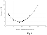
- Fig. 4 illustrates a relationship between the molten metal running index YI and the porosity, which was found in Examples described below.
- the molten metal running index YI is greater than the above-described upper limit, a molten metal does not infiltrate between protrusions, and a void is generated between a cylinder liner and a cylinder block, which results in insufficient joining strength and insufficient heat transfer capability to transfer heat generated in a combustion chamber to cooling water.
- the molten metal running index YI is lower than the above-described lower limit, the molten metal temperature decreases due to the molten metal being in contact with the outer periphery of the cylinder liner base at an early stage without sufficient flow over the protrusions, and the flow of molten metal is inhibited.
- Fig. 5 illustrates the relationship between the porosity and the joining strength, which was found in the Examples described below.
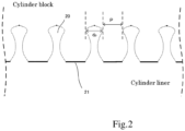
- the plurality of protrusions 10 on the outer periphery 11 of the cylinder liner base has a relatively large diameter d p of the top portion of the protrusion and a relatively small protrusion-to-protrusion distance P, and therefore the plurality of protrusions are densely arranged on the outer periphery 11 of the cylinder liner base.
- the molten metal is difficult to infiltrate between the protrusions. This leads to a vicious cycle in which molten metal takes time to infiltrate between the plurality of protrusions, and the molten metal cools and solidifies faster than the molten metal can infiltrate between the protrusions.
- the plurality of protrusions 20 on the outer periphery 21 of the cylinder liner base has a relatively small diameter d p of the top portion of the protrusion and the protrusion-to-protrusion distance P is relatively large
- the plurality of protrusions are arranged in low density with wide intervals on the outer periphery 21 of the cylinder liner base.
- the molten metal easily infiltrates between the protrusions on the way of sliding and flowing on the plurality of protrusions and touches the outer periphery of the cylinder liner base, causing the molten metal to cool down.
- the molten metal does not flow to every corner of the cylinder liner.
- a cylinder liner which has an optimal arrangement of protrusions to allow molten metal to infiltrate between the protrusions in accordance with the viscosity and the surface tension of molten metal, needed to be developed.
- the area ratio S t (%) of the top portions of the protrusions is the projected area ratio of the protrusions viewed from the outer peripheral side of the cylinder liner in the height direction of the protrusions, and in the case of constricted protrusions, the area ratio S t is the area ratio of portions corresponding to the maximal diameter of the protrusions near the tip.
- the area ratio S t of the top portions of the protrusions is preferably 8 or more, and more preferably 10 or more, and is preferably 35 or less, and more preferably 30 or less.
- the molten metal can easily infiltrate between the protrusions, and the molten metal can be prevented from cooling down through contact with the outer periphery of the cylinder liner base at an early stage.
- the molten metal infiltration volume V (mm 3 ) represents the protrusion-to-protrusion area existing from the outer periphery of the cylinder liner base to the top portions of the protrusions. Therefore, the molten metal infiltration volume V is defined as the volume of a cylinder, whose cylinder diameter is defined as the outermost diameter d max (mm) of the cylinder liner including the protrusions, minus the volume of a cylinder, whose cylinder diameter is defined as the outer diameter d (mm) of the cylinder liner base, and then the product of the number (deemed number of protrusions) ⁇ of the protrusions in the cylinder liner and the volume of protrusions (deemed volume of protrusions) when considering the protrusions to be cylindrical in shape.
- the outer peripheral surface area A (mm 2 ) of the cylinder liner base is the outer peripheral surface area of a cylinder whose cylinder diameter is considered to be the outer diameter d (mm) of the cylinder liner base, and the molten metal infiltration volume V changes significantly depending on the diameter of the cylinder liner, the molten metal infiltration volume V was divided by the peripheral surface area A of the cylinder liner base, which was substantially standardized.
- the number of protrusions per unit area is the number of protrusions present per 1 cm 2 and is preferably 10 or more, and more preferably 15 or more, and is preferably 40 or less, and preferably 35 or less.
- the surface protrusion-to-protrusion distance P can easily be set to an appropriate value.
- the average diameter d pav (mm) of top portions of the protrusions is the diameter of a protrusion calculated from the average projected area of each protrusion viewed from the outer peripheral side of the cylinder liner in the height direction of the protrusion, which corresponds to the diameter of the maximal diameter of the top portion of the protrusion.
- the d pav is preferably 0.7 or more, and more preferably 0.8 or more, and is preferably 1.3 or less, and preferably 1.1 or less.
- the average protrusion height H av (mm) of is not particularly limited, and is usually 0.3 or more, and may be 0.4 or more, and may be usually 0.9 or less, and may be 0.7 or less.
- the area ratio S t , the average diameter d pav , the average surface-to-surface distance P av , and the average protrusion height H av can be measured by a 3D surface measuring instrument.
- the molten metal infiltration volume V (mm 3 )/the outer peripheral surface area A (mm 2 ) of the cylinder liner base is preferably 0.7 mm or less, and more preferably 0.66 mm or less, and the lower limit is preferably 0.3 mm or more.
- the value of the molten metal infiltration volume V (mm 3 )/the outer peripheral surface area A (mm 2 ) of the cylinder liner base is equal to or lower than the above-described upper limit, the molten metal easily infiltrates between the protrusions.
- the average surface-to-surface distance P av (mm) between the top portions of the protrusions refers to the average of the distances between the top portions of adjacent protrusions. As illustrated in Fig. 1 , the distance P between the top portions of the protrusions that can have a maximal diameter indicates the size of an inlet where molten metal flowing on the surface of the cylinder liner can infiltrate into a protrusion-to-protrusion area.
- the average surface-to-surface distance P av (mm) between the top portions of the protrusions can be measured by the following method.
- d max is the average value obtained by measuring a total of 6 points in the X and Y directions at three locations, a top, a middle, and a bottom of one cylinder liner, respectively, using a caliper. The measurement shall be performed with a caliper surely hanging on the tip of the protrusion.
- the average surface-to-surface distance P av between the top portions of the protrusions is calculated by the procedure described in Examples below.
- the cylinder liner of the present embodiment preferably further satisfies the following requirements in order to further improve infiltration of molten metal between protrusions when cast in a cylinder block.
- the plurality of protrusions existing on the outer periphery of the cylinder liner base preferably have a height variation ⁇ H (mm) of 0.3 or less, and more preferably 0.25 or less.
- ⁇ H (mm) of the protrusions is greater than the above, the flow of molten metal on the protrusions may be obstructed, which is undesirable.
- the height variation ⁇ H(mm), which can be measured with a 3D surface measuring instrument, is the difference between the maximum height of protrusions and the minimum height of protrusions in the observation field.
- the plurality of protrusions existing on the outer periphery of the cylinder liner base preferably have a surface roughness Rz of the top portions of the protrusions of 100 ⁇ m or less, and more preferably 75 ⁇ m or less.
- the lower limit of the surface roughness Rz of the top portions of the protrusions is not particularly limited, and is substantially about 10 ⁇ m, and the smaller the surface roughness, the more preferable.
- the surface roughness Rsk of the plurality of the top portions of the protrusions is preferably less than 0 (a negative value).
- the surface roughness Rz and Rsk of the top portions of the protrusions can be measured by laser microscopy.
- composition of a cast iron used as a material for a cylinder liner is not particularly limited, and typically the following composition can be given as an example of a composition of flaky graphite cast iron equivalent to JIS FC250, taking into account the wear resistance, seizure resistance, and workability.
- the method of manufacturing a cylinder liner is not particularly limited, and may be gravity casting or centrifugal casting, but the centrifugal casting method is preferable and typically includes the following processes A to E.
- Process A is a process of preparing a suspension by blending a fire-resistant base material, a binder, and water in a predetermined ratio.
- Diatomaceous earth is typically used as the fire-resistant base material, but other materials can be used as well.
- the content of diatomaceous earth in the suspension is typically from 15% by mass to 35% by mass, and the average particle size of the diatomaceous earth is typically from 0.02 mm to 0.035 mm.
- Bentonite is typically used as the binder, but other materials can be used as well.
- the content of bentonite in the suspension is usually from 3% by mass to 9% by mass.
- the content of water in the suspension is usually from 62% by mass to 80% by mass.
- Process B is a process in which a predetermined amount of a surfactant is added to the suspension prepared in Process A to prepare a coating agent.
- the type of surfactant is not particularly limited, and one of known surfactants such as a cationic surfactant, an anionic surfactant, a nonionic surfactant, or an amphoteric surfactant, or a combination of two or more of these surfactants is used.
- the amount of the surfactant to be blended is usually from 0.003% by mass to 0.04% by mass.
- Process C is a process of applying a coating agent to the inner surface of a cylindrical mold as a template.
- the application method is not particularly limited, and typically a spray application is used.
- a coating agent it is desirable that the coating agent is applied in such a manner that a layer of the coating agent is formed with an approximately uniform thickness over the entire inner surface. It is desirable to apply a moderate centrifugal force by rotating the cylindrical mold during application of a coating agent and formation of a coating agent layer.
- the thickness of the coating agent layer is preferably determined within a range of 1.3 to 1.8 times the height of the protrusions, but is not limited thereto.
- the temperature of the mold is preferably 300°C or less.
- Process D is a process of casting cast iron into a mold including a dry coating agent layer in a rotating state.
- molten metal fills a recessed hole having a constricted shape of the coating agent layer described in the previous process, thereby forming a constricted protrusion on the surface of a cylinder liner. It is also desirable to apply moderate centrifugal force in this process.
- Process E the manufactured cylinder liner is retrieved from the mold, and the coating agent layer on the surface of the cylinder liner is removed from the cylinder liner by blasting, thereby completing the cylinder liner.
- the cylinder liner is completed through the above processes.
- the spacing between the protrusions is moderately wide and the area ratio of the top portions of the protrusions is moderately large.
- the protrusions on the outer periphery of the cylinder liner base can have a desired shape.
- the surface roughnesses Rsk and Rz of the top portions of the protrusions can be set to appropriate values by adjusting the type of fire-resistant material and the particle size of the diatomaceous earth in the above Process E. By reducing the particle size of the media used in the blasting process, the surface roughness of the top portions of the protrusions can be reduced.
- the cylinder liner of the present embodiment is joined with a cylinder block to become a composite.
- a known method can be employed to manufacture a composite, and one example of such method may include a process of preparing a mold for a cylinder block, a process of arranging the cylinder liner of the present embodiment in the prepared mold for the cylinder block, and a process of pouring molten metal into the mold for the cylinder block in which the cylinder liner is arranged to form the cylinder block.
- the protrusion-to-protrusion distance and the protrusion area ratio of the outer periphery of the cylinder liner base are within appropriate ranges, and therefore, the molten metal that forms the cylinder block slides on the protrusions of the cylinder liner without touching the outer periphery of the cylinder liner base at an early stage to cool down the molten metal, and spreads to every corner of the mold for the cylinder block.
- the molten metal also spreads between the protrusions on the outer periphery of the cylinder liner base, which reduces voids at an interface between the cylinder liner and the cylinder block and improves the joining force between the cylinder liner and the cylinder block.
- the porosity of the cylinder block is preferably 5.0% or less, more preferably 4.8% or less, still more preferably 4.0% or less, and particularly preferably 3.0% or less.
- the lower limit is not particularly limited, and is usually 0% or more.
- the constriction rate of the protrusions was calculated by using a microscope (KH-1300, a digital microscope manufactured by HIROX CO., LTD.) and observing any 20 protrusions from an oblique direction and determining the number of protrusions which were found to be constricted. The average of the four locations measured per cylinder liner was used as the constriction rate.
- the method of measuring the average surface-to-surface distance P av between top portions of the protrusions was carried out by the following procedure.
- the characteristics of the cylinder liner can be more easily evaluated.
- the constriction rate of protrusion, the area ratio S t , the average diameter d pav , H av , ⁇ H, and the average surface-to-surface distance P av between top portions of protrusions were averaged over four locations (four fields of view) per cylinder liner.
- the four locations are preferably, but not limited to, two opposing locations about 20 mm from both ends of the cylinder liner, and the two locations are preferably displaced by about 90° from each other at both ends.
- the measurement method of the surface roughness of the top portions of the protrusions was as follows.
- the following raw materials were used to prepare a coating agent.
- Cylinder liners of Examples and Comparative Examples were prepared by centrifugal casting using molten metal of the following composition.
- the composition of the cast cylinder liners was as follows:
- the cylinder liners for Examples 1 to 10 and Comparative Examples 1 to 5 shown in Table 1 were prepared.
- the temperature of the cylindrical mold in Process C was changed appropriately in the range of from 220 to 280°C, and a coating agent layer was formed with Gno (lining) of from 40 to 70 G
- the thickness of the coating agent layer was changed in the range of from 0.7 to 1.3 mm to change the protrusion height accordingly.
- cast iron was cast at a Gno (casting) of from 100 to 130 G and a mold temperature of from 200 to 260°C. The inner surface of the obtained cast iron cylindrical member was cut and the wall thickness was adjusted.
- the dimensions of the cast iron cylindrical member thus obtained were 86 mm in outer diameter (outer diameter including the height of the protrusion) and 77 mm in inner diameter, and the axial length, excluding chamfered portions, was 133 mm.
- the properties of the protrusions of the prepared cylinder liners are shown in Table 2.
- Example 1 Area ratio of top portion of protrusion St [%] Average diameter of top portion of protrusion d pav [mm] Average protrusion height Hav [mm] Protrusion height variation ⁇ H [mm] Average surface-to-surface distance Pav [mm] V/A [mm] Molten metal running index YI Surface roughness of top portion of protrusion Rz [ ⁇ m] Joining strength evaluation*
- Example 1 8.1 0.70 0.49 0.11 1.644 0.45 2.2 32.0
- Example 2 20.2 0.80 0.50 0.22 0.897 0.40 9.0 69.0
- Example 3 31.9 1.08 0.49 0.18 0.739 0.33 14.4 58.4 A
- Example 4 20.4 1.32 0.49 0.18 1.459 0.39 5.5 50.5
- Example 5 15.8 0.83 0.59 0.25 1.163 0.50 6.8 60.8
- Example 6 10.1 0.93 0.56 0.12 1.849 0.51 2.8 24.3
- a Example 7 34.5 1.31 0.51 0.19 0.816 0.34 14.3 33.3
- the resulting joined bodies of the cylinder liner and the cylinder block were measured for the porosity of the cylinder block using the following method.
- the porosity of the cylinder block is preferably 5.0% or less. It can be understood that in order to form a cylinder block having a desired porosity, it is preferable to use a cylinder liner having a molten metal running index YI of 2.2 or more.
Landscapes
- Engineering & Computer Science (AREA)
- Mechanical Engineering (AREA)
- General Engineering & Computer Science (AREA)
- Chemical & Material Sciences (AREA)
- Combustion & Propulsion (AREA)
- Cylinder Crankcases Of Internal Combustion Engines (AREA)
- Pistons, Piston Rings, And Cylinders (AREA)
Applications Claiming Priority (1)
| Application Number | Priority Date | Filing Date | Title |
|---|---|---|---|
| PCT/JP2020/024707 WO2021260819A1 (ja) | 2020-06-24 | 2020-06-24 | 鋳包み用シリンダライナ |
Publications (3)
| Publication Number | Publication Date |
|---|---|
| EP3957415A1 EP3957415A1 (en) | 2022-02-23 |
| EP3957415A4 EP3957415A4 (en) | 2022-06-01 |
| EP3957415B1 true EP3957415B1 (en) | 2023-08-09 |
Family
ID=73022494
Family Applications (1)
| Application Number | Title | Priority Date | Filing Date |
|---|---|---|---|
| EP20873383.2A Active EP3957415B1 (en) | 2020-06-24 | 2020-06-24 | Cylinder liner for insert casting |
Country Status (10)
| Country | Link |
|---|---|
| US (1) | US11141783B1 (pl) |
| EP (1) | EP3957415B1 (pl) |
| JP (1) | JP6780156B1 (pl) |
| KR (1) | KR102265427B1 (pl) |
| CN (2) | CN214517524U (pl) |
| BR (1) | BR112021013900B8 (pl) |
| MX (1) | MX2021005503A (pl) |
| PL (1) | PL3957415T3 (pl) |
| RU (1) | RU2767129C1 (pl) |
| WO (1) | WO2021260819A1 (pl) |
Families Citing this family (2)
| Publication number | Priority date | Publication date | Assignee | Title |
|---|---|---|---|---|
| PL3957415T3 (pl) * | 2020-06-24 | 2023-12-04 | Tpr Co., Ltd. | Tuleja cylindrowa do odlewania z wkładką |
| JP7514799B2 (ja) * | 2021-06-09 | 2024-07-11 | Tpr株式会社 | シリンダライナ |
Family Cites Families (15)
| Publication number | Priority date | Publication date | Assignee | Title |
|---|---|---|---|---|
| JPS5724666A (en) | 1980-07-18 | 1982-02-09 | Matsushita Electric Ind Co Ltd | Ultrasonic atomizer |
| JP3161301B2 (ja) * | 1995-02-21 | 2001-04-25 | トヨタ自動車株式会社 | 鋳ぐるみ用シリンダライナ |
| JP3253605B2 (ja) | 1999-12-15 | 2002-02-04 | テーピ工業株式会社 | 鋳ぐるみ用鋳鉄部材、それを用いた鋳ぐるみ製品、及び鋳ぐるみ用鋳鉄部材の製造方法 |
| WO2003095129A1 (en) * | 2002-05-13 | 2003-11-20 | Honda Giken Kogyo Kabushiki Kaisha | Cast iron internal chill member and method of producing the same |
| JP4210469B2 (ja) * | 2002-05-13 | 2009-01-21 | 本田技研工業株式会社 | 鋳鉄製鋳ぐるみ部材の製造方法 |
| JP4429025B2 (ja) * | 2004-01-09 | 2010-03-10 | トヨタ自動車株式会社 | 鋳包み用シリンダライナ |
| JP4491385B2 (ja) * | 2005-07-08 | 2010-06-30 | トヨタ自動車株式会社 | 鋳ぐるみ用部品、シリンダブロック及びシリンダライナ製造方法 |
| JP4452661B2 (ja) * | 2005-07-08 | 2010-04-21 | トヨタ自動車株式会社 | 鋳ぐるみ用部品、シリンダブロック、鋳ぐるみ用部品被膜形成方法及びシリンダブロック製造方法 |
| JP4512001B2 (ja) * | 2005-07-08 | 2010-07-28 | トヨタ自動車株式会社 | シリンダライナ、シリンダブロック及びシリンダライナ製造方法 |
| JP2008138552A (ja) * | 2006-11-30 | 2008-06-19 | Nippon Piston Ring Co Ltd | シリンダライナ |
| JP5388475B2 (ja) | 2008-04-30 | 2014-01-15 | Tpr株式会社 | 鋳包構造体 |
| JP2012067740A (ja) * | 2010-08-25 | 2012-04-05 | Tpr Co Ltd | 鋳包用シリンダライナ |
| KR101927284B1 (ko) | 2017-11-17 | 2018-12-10 | 티피알 가부시키가이샤 | 주철제 원통부재 및 복합 구조체 |
| CN109915273B (zh) * | 2018-05-24 | 2020-06-30 | 帝伯爱尔株式会社 | 圆筒部件 |
| PL3957415T3 (pl) * | 2020-06-24 | 2023-12-04 | Tpr Co., Ltd. | Tuleja cylindrowa do odlewania z wkładką |
-
2020
- 2020-06-24 PL PL20873383.2T patent/PL3957415T3/pl unknown
- 2020-06-24 EP EP20873383.2A patent/EP3957415B1/en active Active
- 2020-06-24 MX MX2021005503A patent/MX2021005503A/es unknown
- 2020-06-24 WO PCT/JP2020/024707 patent/WO2021260819A1/ja not_active Ceased
- 2020-06-24 JP JP2020544886A patent/JP6780156B1/ja active Active
- 2020-06-24 KR KR1020217011418A patent/KR102265427B1/ko active Active
- 2020-06-24 RU RU2021121882A patent/RU2767129C1/ru active
- 2020-06-24 BR BR112021013900A patent/BR112021013900B8/pt active IP Right Grant
- 2020-11-10 CN CN202022591912.4U patent/CN214517524U/zh not_active Withdrawn - After Issue
- 2020-11-10 CN CN202011253418.5A patent/CN112719247B/zh active Active
-
2021
- 2021-05-03 US US17/246,799 patent/US11141783B1/en active Active
Also Published As
| Publication number | Publication date |
|---|---|
| EP3957415A4 (en) | 2022-06-01 |
| PL3957415T3 (pl) | 2023-12-04 |
| EP3957415A1 (en) | 2022-02-23 |
| CN112719247B (zh) | 2022-06-24 |
| BR112021013900A2 (pt) | 2022-02-01 |
| JPWO2021260819A1 (pl) | 2021-12-30 |
| KR102265427B1 (ko) | 2021-06-14 |
| US11141783B1 (en) | 2021-10-12 |
| WO2021260819A1 (ja) | 2021-12-30 |
| MX2021005503A (es) | 2022-01-24 |
| BR112021013900B8 (pt) | 2022-11-16 |
| RU2767129C1 (ru) | 2022-03-16 |
| CN214517524U (zh) | 2021-10-29 |
| CN112719247A (zh) | 2021-04-30 |
| JP6780156B1 (ja) | 2020-11-04 |
| BR112021013900B1 (pt) | 2022-08-30 |
Similar Documents
| Publication | Publication Date | Title |
|---|---|---|
| EP1711291B1 (en) | Cylinder liner for insert casting | |
| EP3779162B1 (en) | Cylinder liner for cast-covering, and method for manufacturing cylinder block | |
| JP3253605B2 (ja) | 鋳ぐるみ用鋳鉄部材、それを用いた鋳ぐるみ製品、及び鋳ぐるみ用鋳鉄部材の製造方法 | |
| US11141783B1 (en) | Cylinder liner for insert casting | |
| JP6340148B1 (ja) | 鋳鉄製円筒部材および複合構造体 | |
| KR102812058B1 (ko) | 스파이니 라이너 및 그 제조 방법, 그리고 접합 강도의 감별법 | |
| JP7514799B2 (ja) | シリンダライナ | |
| RU2808095C1 (ru) | Игольчатая гильза и способ ее изготовления, и способ определения прочности соединения |
Legal Events
| Date | Code | Title | Description |
|---|---|---|---|
| STAA | Information on the status of an ep patent application or granted ep patent |
Free format text: STATUS: UNKNOWN |
|
| STAA | Information on the status of an ep patent application or granted ep patent |
Free format text: STATUS: THE INTERNATIONAL PUBLICATION HAS BEEN MADE |
|
| PUAI | Public reference made under article 153(3) epc to a published international application that has entered the european phase |
Free format text: ORIGINAL CODE: 0009012 |
|
| STAA | Information on the status of an ep patent application or granted ep patent |
Free format text: STATUS: REQUEST FOR EXAMINATION WAS MADE |
|
| 17P | Request for examination filed |
Effective date: 20210416 |
|
| AK | Designated contracting states |
Kind code of ref document: A1 Designated state(s): AL AT BE BG CH CY CZ DE DK EE ES FI FR GB GR HR HU IE IS IT LI LT LU LV MC MK MT NL NO PL PT RO RS SE SI SK SM TR |
|
| RIN1 | Information on inventor provided before grant (corrected) |
Inventor name: KAWAI, KIYOYUKI Inventor name: HATAKEYAMA, KOICHI Inventor name: TOKAIRIN, YASUTOMO |
|
| A4 | Supplementary search report drawn up and despatched |
Effective date: 20220503 |
|
| RIC1 | Information provided on ipc code assigned before grant |
Ipc: F02F 1/00 20060101ALI20220426BHEP Ipc: B22D 19/00 20060101ALI20220426BHEP Ipc: F16J 10/04 20060101ALI20220426BHEP Ipc: F02F 1/10 20060101ALI20220426BHEP Ipc: B22D 19/08 20060101ALI20220426BHEP Ipc: B22D 17/32 20060101ALI20220426BHEP Ipc: B22D 17/00 20060101AFI20220426BHEP |
|
| RIN1 | Information on inventor provided before grant (corrected) |
Inventor name: KAWAI, KIYOYUKI Inventor name: HATAKEYAMA, KOICHI Inventor name: TOKAIRIN, YASUTOMO |
|
| GRAP | Despatch of communication of intention to grant a patent |
Free format text: ORIGINAL CODE: EPIDOSNIGR1 |
|
| RIC1 | Information provided on ipc code assigned before grant |
Ipc: F02F 1/00 20060101ALI20230123BHEP Ipc: B22D 19/00 20060101ALI20230123BHEP Ipc: F16J 10/04 20060101ALI20230123BHEP Ipc: F02F 1/10 20060101ALI20230123BHEP Ipc: B22D 19/08 20060101ALI20230123BHEP Ipc: B22D 17/32 20060101ALI20230123BHEP Ipc: B22D 17/00 20060101AFI20230123BHEP |
|
| STAA | Information on the status of an ep patent application or granted ep patent |
Free format text: STATUS: GRANT OF PATENT IS INTENDED |
|
| INTG | Intention to grant announced |
Effective date: 20230302 |
|
| GRAS | Grant fee paid |
Free format text: ORIGINAL CODE: EPIDOSNIGR3 |
|
| GRAA | (expected) grant |
Free format text: ORIGINAL CODE: 0009210 |
|
| STAA | Information on the status of an ep patent application or granted ep patent |
Free format text: STATUS: THE PATENT HAS BEEN GRANTED |
|
| AK | Designated contracting states |
Kind code of ref document: B1 Designated state(s): AL AT BE BG CH CY CZ DE DK EE ES FI FR GB GR HR HU IE IS IT LI LT LU LV MC MK MT NL NO PL PT RO RS SE SI SK SM TR |
|
| DAV | Request for validation of the european patent (deleted) | ||
| DAX | Request for extension of the european patent (deleted) | ||
| REG | Reference to a national code |
Ref country code: GB Ref legal event code: FG4D |
|
| REG | Reference to a national code |
Ref country code: CH Ref legal event code: EP |
|
| REG | Reference to a national code |
Ref country code: IE Ref legal event code: FG4D |
|
| REG | Reference to a national code |
Ref country code: DE Ref legal event code: R096 Ref document number: 602020015631 Country of ref document: DE |
|
| REG | Reference to a national code |
Ref country code: LT Ref legal event code: MG9D |
|
| REG | Reference to a national code |
Ref country code: NL Ref legal event code: MP Effective date: 20230809 |
|
| REG | Reference to a national code |
Ref country code: AT Ref legal event code: MK05 Ref document number: 1596905 Country of ref document: AT Kind code of ref document: T Effective date: 20230809 |
|
| PG25 | Lapsed in a contracting state [announced via postgrant information from national office to epo] |
Ref country code: GR Free format text: LAPSE BECAUSE OF FAILURE TO SUBMIT A TRANSLATION OF THE DESCRIPTION OR TO PAY THE FEE WITHIN THE PRESCRIBED TIME-LIMIT Effective date: 20231110 |
|
| PG25 | Lapsed in a contracting state [announced via postgrant information from national office to epo] |
Ref country code: IS Free format text: LAPSE BECAUSE OF FAILURE TO SUBMIT A TRANSLATION OF THE DESCRIPTION OR TO PAY THE FEE WITHIN THE PRESCRIBED TIME-LIMIT Effective date: 20231209 |
|
| PG25 | Lapsed in a contracting state [announced via postgrant information from national office to epo] |
Ref country code: SE Free format text: LAPSE BECAUSE OF FAILURE TO SUBMIT A TRANSLATION OF THE DESCRIPTION OR TO PAY THE FEE WITHIN THE PRESCRIBED TIME-LIMIT Effective date: 20230809 Ref country code: RS Free format text: LAPSE BECAUSE OF FAILURE TO SUBMIT A TRANSLATION OF THE DESCRIPTION OR TO PAY THE FEE WITHIN THE PRESCRIBED TIME-LIMIT Effective date: 20230809 Ref country code: PT Free format text: LAPSE BECAUSE OF FAILURE TO SUBMIT A TRANSLATION OF THE DESCRIPTION OR TO PAY THE FEE WITHIN THE PRESCRIBED TIME-LIMIT Effective date: 20231211 Ref country code: NO Free format text: LAPSE BECAUSE OF FAILURE TO SUBMIT A TRANSLATION OF THE DESCRIPTION OR TO PAY THE FEE WITHIN THE PRESCRIBED TIME-LIMIT Effective date: 20231109 Ref country code: NL Free format text: LAPSE BECAUSE OF FAILURE TO SUBMIT A TRANSLATION OF THE DESCRIPTION OR TO PAY THE FEE WITHIN THE PRESCRIBED TIME-LIMIT Effective date: 20230809 Ref country code: LV Free format text: LAPSE BECAUSE OF FAILURE TO SUBMIT A TRANSLATION OF THE DESCRIPTION OR TO PAY THE FEE WITHIN THE PRESCRIBED TIME-LIMIT Effective date: 20230809 Ref country code: LT Free format text: LAPSE BECAUSE OF FAILURE TO SUBMIT A TRANSLATION OF THE DESCRIPTION OR TO PAY THE FEE WITHIN THE PRESCRIBED TIME-LIMIT Effective date: 20230809 Ref country code: IS Free format text: LAPSE BECAUSE OF FAILURE TO SUBMIT A TRANSLATION OF THE DESCRIPTION OR TO PAY THE FEE WITHIN THE PRESCRIBED TIME-LIMIT Effective date: 20231209 Ref country code: HR Free format text: LAPSE BECAUSE OF FAILURE TO SUBMIT A TRANSLATION OF THE DESCRIPTION OR TO PAY THE FEE WITHIN THE PRESCRIBED TIME-LIMIT Effective date: 20230809 Ref country code: GR Free format text: LAPSE BECAUSE OF FAILURE TO SUBMIT A TRANSLATION OF THE DESCRIPTION OR TO PAY THE FEE WITHIN THE PRESCRIBED TIME-LIMIT Effective date: 20231110 Ref country code: FI Free format text: LAPSE BECAUSE OF FAILURE TO SUBMIT A TRANSLATION OF THE DESCRIPTION OR TO PAY THE FEE WITHIN THE PRESCRIBED TIME-LIMIT Effective date: 20230809 Ref country code: AT Free format text: LAPSE BECAUSE OF FAILURE TO SUBMIT A TRANSLATION OF THE DESCRIPTION OR TO PAY THE FEE WITHIN THE PRESCRIBED TIME-LIMIT Effective date: 20230809 |
|
| PG25 | Lapsed in a contracting state [announced via postgrant information from national office to epo] |
Ref country code: ES Free format text: LAPSE BECAUSE OF FAILURE TO SUBMIT A TRANSLATION OF THE DESCRIPTION OR TO PAY THE FEE WITHIN THE PRESCRIBED TIME-LIMIT Effective date: 20230809 |
|
| PG25 | Lapsed in a contracting state [announced via postgrant information from national office to epo] |
Ref country code: SM Free format text: LAPSE BECAUSE OF FAILURE TO SUBMIT A TRANSLATION OF THE DESCRIPTION OR TO PAY THE FEE WITHIN THE PRESCRIBED TIME-LIMIT Effective date: 20230809 Ref country code: RO Free format text: LAPSE BECAUSE OF FAILURE TO SUBMIT A TRANSLATION OF THE DESCRIPTION OR TO PAY THE FEE WITHIN THE PRESCRIBED TIME-LIMIT Effective date: 20230809 Ref country code: ES Free format text: LAPSE BECAUSE OF FAILURE TO SUBMIT A TRANSLATION OF THE DESCRIPTION OR TO PAY THE FEE WITHIN THE PRESCRIBED TIME-LIMIT Effective date: 20230809 Ref country code: EE Free format text: LAPSE BECAUSE OF FAILURE TO SUBMIT A TRANSLATION OF THE DESCRIPTION OR TO PAY THE FEE WITHIN THE PRESCRIBED TIME-LIMIT Effective date: 20230809 Ref country code: DK Free format text: LAPSE BECAUSE OF FAILURE TO SUBMIT A TRANSLATION OF THE DESCRIPTION OR TO PAY THE FEE WITHIN THE PRESCRIBED TIME-LIMIT Effective date: 20230809 Ref country code: CZ Free format text: LAPSE BECAUSE OF FAILURE TO SUBMIT A TRANSLATION OF THE DESCRIPTION OR TO PAY THE FEE WITHIN THE PRESCRIBED TIME-LIMIT Effective date: 20230809 Ref country code: SK Free format text: LAPSE BECAUSE OF FAILURE TO SUBMIT A TRANSLATION OF THE DESCRIPTION OR TO PAY THE FEE WITHIN THE PRESCRIBED TIME-LIMIT Effective date: 20230809 |
|
| REG | Reference to a national code |
Ref country code: DE Ref legal event code: R097 Ref document number: 602020015631 Country of ref document: DE |
|
| PLBE | No opposition filed within time limit |
Free format text: ORIGINAL CODE: 0009261 |
|
| STAA | Information on the status of an ep patent application or granted ep patent |
Free format text: STATUS: NO OPPOSITION FILED WITHIN TIME LIMIT |
|
| 26N | No opposition filed |
Effective date: 20240513 |
|
| PG25 | Lapsed in a contracting state [announced via postgrant information from national office to epo] |
Ref country code: SI Free format text: LAPSE BECAUSE OF FAILURE TO SUBMIT A TRANSLATION OF THE DESCRIPTION OR TO PAY THE FEE WITHIN THE PRESCRIBED TIME-LIMIT Effective date: 20230809 |
|
| PG25 | Lapsed in a contracting state [announced via postgrant information from national office to epo] |
Ref country code: BG Free format text: LAPSE BECAUSE OF FAILURE TO SUBMIT A TRANSLATION OF THE DESCRIPTION OR TO PAY THE FEE WITHIN THE PRESCRIBED TIME-LIMIT Effective date: 20230809 |
|
| PG25 | Lapsed in a contracting state [announced via postgrant information from national office to epo] |
Ref country code: BG Free format text: LAPSE BECAUSE OF FAILURE TO SUBMIT A TRANSLATION OF THE DESCRIPTION OR TO PAY THE FEE WITHIN THE PRESCRIBED TIME-LIMIT Effective date: 20230809 |
|
| PG25 | Lapsed in a contracting state [announced via postgrant information from national office to epo] |
Ref country code: MC Free format text: LAPSE BECAUSE OF FAILURE TO SUBMIT A TRANSLATION OF THE DESCRIPTION OR TO PAY THE FEE WITHIN THE PRESCRIBED TIME-LIMIT Effective date: 20230809 |
|
| REG | Reference to a national code |
Ref country code: CH Ref legal event code: PL |
|
| PG25 | Lapsed in a contracting state [announced via postgrant information from national office to epo] |
Ref country code: LU Free format text: LAPSE BECAUSE OF NON-PAYMENT OF DUE FEES Effective date: 20240624 |
|
| GBPC | Gb: european patent ceased through non-payment of renewal fee |
Effective date: 20240624 |
|
| PG25 | Lapsed in a contracting state [announced via postgrant information from national office to epo] |
Ref country code: IE Free format text: LAPSE BECAUSE OF NON-PAYMENT OF DUE FEES Effective date: 20240624 |
|
| PG25 | Lapsed in a contracting state [announced via postgrant information from national office to epo] |
Ref country code: BE Free format text: LAPSE BECAUSE OF NON-PAYMENT OF DUE FEES Effective date: 20240630 Ref country code: CH Free format text: LAPSE BECAUSE OF NON-PAYMENT OF DUE FEES Effective date: 20240630 |
|
| PG25 | Lapsed in a contracting state [announced via postgrant information from national office to epo] |
Ref country code: FR Free format text: LAPSE BECAUSE OF NON-PAYMENT OF DUE FEES Effective date: 20240630 |
|
| PG25 | Lapsed in a contracting state [announced via postgrant information from national office to epo] |
Ref country code: GB Free format text: LAPSE BECAUSE OF NON-PAYMENT OF DUE FEES Effective date: 20240624 |
|
| REG | Reference to a national code |
Ref country code: BE Ref legal event code: MM Effective date: 20240630 |
|
| PGFP | Annual fee paid to national office [announced via postgrant information from national office to epo] |
Ref country code: PL Payment date: 20250612 Year of fee payment: 6 Ref country code: DE Payment date: 20250618 Year of fee payment: 6 |
|
| PGFP | Annual fee paid to national office [announced via postgrant information from national office to epo] |
Ref country code: TR Payment date: 20250620 Year of fee payment: 6 |
|
| PGFP | Annual fee paid to national office [announced via postgrant information from national office to epo] |
Ref country code: IT Payment date: 20250630 Year of fee payment: 6 |
|
| PG25 | Lapsed in a contracting state [announced via postgrant information from national office to epo] |
Ref country code: CY Free format text: LAPSE BECAUSE OF FAILURE TO SUBMIT A TRANSLATION OF THE DESCRIPTION OR TO PAY THE FEE WITHIN THE PRESCRIBED TIME-LIMIT; INVALID AB INITIO Effective date: 20200624 |
|
| PG25 | Lapsed in a contracting state [announced via postgrant information from national office to epo] |
Ref country code: HU Free format text: LAPSE BECAUSE OF FAILURE TO SUBMIT A TRANSLATION OF THE DESCRIPTION OR TO PAY THE FEE WITHIN THE PRESCRIBED TIME-LIMIT; INVALID AB INITIO Effective date: 20200624 |