EP3956909B1 - Spulen-modul und verfahren zur herstellung einer spulen-anordnung - Google Patents
Spulen-modul und verfahren zur herstellung einer spulen-anordnung Download PDFInfo
- Publication number
- EP3956909B1 EP3956909B1 EP21703671.4A EP21703671A EP3956909B1 EP 3956909 B1 EP3956909 B1 EP 3956909B1 EP 21703671 A EP21703671 A EP 21703671A EP 3956909 B1 EP3956909 B1 EP 3956909B1
- Authority
- EP
- European Patent Office
- Prior art keywords
- coil
- carrier
- module according
- modules
- coil module
- Prior art date
- Legal status (The legal status is an assumption and is not a legal conclusion. Google has not performed a legal analysis and makes no representation as to the accuracy of the status listed.)
- Active
Links
Images


Classifications
-
- H—ELECTRICITY
- H01—ELECTRIC ELEMENTS
- H01F—MAGNETS; INDUCTANCES; TRANSFORMERS; SELECTION OF MATERIALS FOR THEIR MAGNETIC PROPERTIES
- H01F27/00—Details of transformers or inductances, in general
- H01F27/28—Coils; Windings; Conductive connections
- H01F27/30—Fastening or clamping coils, windings, or parts thereof together; Fastening or mounting coils or windings on core, casing, or other support
- H01F27/306—Fastening or mounting coils or windings on core, casing or other support
-
- H—ELECTRICITY
- H01—ELECTRIC ELEMENTS
- H01F—MAGNETS; INDUCTANCES; TRANSFORMERS; SELECTION OF MATERIALS FOR THEIR MAGNETIC PROPERTIES
- H01F5/00—Coils
-
- H—ELECTRICITY
- H01—ELECTRIC ELEMENTS
- H01F—MAGNETS; INDUCTANCES; TRANSFORMERS; SELECTION OF MATERIALS FOR THEIR MAGNETIC PROPERTIES
- H01F27/00—Details of transformers or inductances, in general
- H01F27/24—Magnetic cores
- H01F27/26—Fastening parts of the core together; Fastening or mounting the core on casing or support
- H01F27/263—Fastening parts of the core together
-
- H—ELECTRICITY
- H01—ELECTRIC ELEMENTS
- H01F—MAGNETS; INDUCTANCES; TRANSFORMERS; SELECTION OF MATERIALS FOR THEIR MAGNETIC PROPERTIES
- H01F27/00—Details of transformers or inductances, in general
- H01F27/24—Magnetic cores
- H01F27/26—Fastening parts of the core together; Fastening or mounting the core on casing or support
- H01F27/266—Fastening or mounting the core on casing or support
-
- H—ELECTRICITY
- H01—ELECTRIC ELEMENTS
- H01F—MAGNETS; INDUCTANCES; TRANSFORMERS; SELECTION OF MATERIALS FOR THEIR MAGNETIC PROPERTIES
- H01F27/00—Details of transformers or inductances, in general
- H01F27/28—Coils; Windings; Conductive connections
- H01F27/30—Fastening or clamping coils, windings, or parts thereof together; Fastening or mounting coils or windings on core, casing, or other support
-
- H—ELECTRICITY
- H01—ELECTRIC ELEMENTS
- H01F—MAGNETS; INDUCTANCES; TRANSFORMERS; SELECTION OF MATERIALS FOR THEIR MAGNETIC PROPERTIES
- H01F27/00—Details of transformers or inductances, in general
- H01F27/34—Special means for preventing or reducing unwanted electric or magnetic effects, e.g. no-load losses, reactive currents, harmonics, oscillations, leakage fields
- H01F27/36—Electric or magnetic shields or screens
- H01F27/366—Electric or magnetic shields or screens made of ferromagnetic material
-
- H—ELECTRICITY
- H01—ELECTRIC ELEMENTS
- H01F—MAGNETS; INDUCTANCES; TRANSFORMERS; SELECTION OF MATERIALS FOR THEIR MAGNETIC PROPERTIES
- H01F38/00—Adaptations of transformers or inductances for specific applications or functions
- H01F38/14—Inductive couplings
-
- H—ELECTRICITY
- H01—ELECTRIC ELEMENTS
- H01F—MAGNETS; INDUCTANCES; TRANSFORMERS; SELECTION OF MATERIALS FOR THEIR MAGNETIC PROPERTIES
- H01F41/00—Apparatus or processes specially adapted for manufacturing or assembling magnets, inductances or transformers; Apparatus or processes specially adapted for manufacturing materials characterised by their magnetic properties
- H01F41/02—Apparatus or processes specially adapted for manufacturing or assembling magnets, inductances or transformers; Apparatus or processes specially adapted for manufacturing materials characterised by their magnetic properties for manufacturing cores, coils, or magnets
- H01F41/04—Apparatus or processes specially adapted for manufacturing or assembling magnets, inductances or transformers; Apparatus or processes specially adapted for manufacturing materials characterised by their magnetic properties for manufacturing cores, coils, or magnets for manufacturing coils
-
- H—ELECTRICITY
- H02—GENERATION; CONVERSION OR DISTRIBUTION OF ELECTRIC POWER
- H02J—ELECTRIC POWER NETWORKS; CIRCUIT ARRANGEMENTS OR SYSTEMS FOR SUPPLYING OR DISTRIBUTING ELECTRIC POWER; SYSTEMS FOR STORING ELECTRIC ENERGY
- H02J50/00—Circuit arrangements or systems for wireless supply or distribution of electric power
- H02J50/005—Mechanical details of housing or structure aiming to accommodate the power transfer means, e.g. mechanical integration of coils, antennas or transducers into emitting or receiving devices
-
- Y—GENERAL TAGGING OF NEW TECHNOLOGICAL DEVELOPMENTS; GENERAL TAGGING OF CROSS-SECTIONAL TECHNOLOGIES SPANNING OVER SEVERAL SECTIONS OF THE IPC; TECHNICAL SUBJECTS COVERED BY FORMER USPC CROSS-REFERENCE ART COLLECTIONS [XRACs] AND DIGESTS
- Y02—TECHNOLOGIES OR APPLICATIONS FOR MITIGATION OR ADAPTATION AGAINST CLIMATE CHANGE
- Y02T—CLIMATE CHANGE MITIGATION TECHNOLOGIES RELATED TO TRANSPORTATION
- Y02T10/00—Road transport of goods or passengers
- Y02T10/60—Other road transportation technologies with climate change mitigation effect
- Y02T10/70—Energy storage systems for electromobility, e.g. batteries
-
- Y—GENERAL TAGGING OF NEW TECHNOLOGICAL DEVELOPMENTS; GENERAL TAGGING OF CROSS-SECTIONAL TECHNOLOGIES SPANNING OVER SEVERAL SECTIONS OF THE IPC; TECHNICAL SUBJECTS COVERED BY FORMER USPC CROSS-REFERENCE ART COLLECTIONS [XRACs] AND DIGESTS
- Y02—TECHNOLOGIES OR APPLICATIONS FOR MITIGATION OR ADAPTATION AGAINST CLIMATE CHANGE
- Y02T—CLIMATE CHANGE MITIGATION TECHNOLOGIES RELATED TO TRANSPORTATION
- Y02T10/00—Road transport of goods or passengers
- Y02T10/60—Other road transportation technologies with climate change mitigation effect
- Y02T10/7072—Electromobility specific charging systems or methods for batteries, ultracapacitors, supercapacitors or double-layer capacitors
-
- Y—GENERAL TAGGING OF NEW TECHNOLOGICAL DEVELOPMENTS; GENERAL TAGGING OF CROSS-SECTIONAL TECHNOLOGIES SPANNING OVER SEVERAL SECTIONS OF THE IPC; TECHNICAL SUBJECTS COVERED BY FORMER USPC CROSS-REFERENCE ART COLLECTIONS [XRACs] AND DIGESTS
- Y02—TECHNOLOGIES OR APPLICATIONS FOR MITIGATION OR ADAPTATION AGAINST CLIMATE CHANGE
- Y02T—CLIMATE CHANGE MITIGATION TECHNOLOGIES RELATED TO TRANSPORTATION
- Y02T90/00—Enabling technologies or technologies with a potential or indirect contribution to GHG emissions mitigation
- Y02T90/10—Technologies relating to charging of electric vehicles
- Y02T90/14—Plug-in electric vehicles
Definitions
- the invention relates to a coil module for producing a coil arrangement and a coil arrangement with at least two such coil modules. Furthermore, the invention relates to a method for producing a coil arrangement.
- the device is used, for example, to charge electric vehicles.
- the device comprises a stationary base charging system and a vehicle charging system arranged in the electric vehicle.
- the basic charging system includes, for example, two coils that are arranged next to one another on a ferrite plate and are connected to one another.
- the charging device comprises a magnetic core and coils arranged thereon.
- the magnetic core comprises rods arranged in a triangle or star shape.
- the inductive energy transmission system comprises coil modules arranged side by side, each comprising a hexagonal carrier with a coil arranged thereon.
- the object of the invention is to provide a coil module that enables an efficient coil arrangement for wireless electromagnetic energy transmission to be produced in a simple and flexible manner.
- the coil is arranged on the carrier in order to generate an electromagnetic field.
- the coil module preferably includes exactly one coil.
- the coil is preferably arranged within the polygonal basic shape. In other words, the turns of the coil do not extend laterally beyond the support.
- the coils of the coil modules can be easily and flexibly connected in series and/or in parallel. As a result, the electrical properties of the coil arrangement can be easily and flexibly adapted in the desired manner.
- the carrier comprises a magnetic material
- the electromagnetic field can be guided and/or shielded in a simple and flexible manner.
- the magnetic material is a ferrite material.
- the ferrite material includes manganese and zinc.
- the carrier is preferably made of the magnetic material.
- the carrier can be connected to other carriers of adjacent coil modules.
- the fastening elements are preferably used for the positive and/or frictional and/or material connection.
- the carrier preferably has at least one first fastening element and at least one second fastening element, which are designed differently from one another.
- the respective second fastening element is preferably formed negatively with respect to the respective first fastening element. In this way, a first fastening element of a carrier can be connected to a second fastening element of another carrier and vice versa. This enables the coil modules to be connected easily and flexibly to form a coil arrangement.
- the coil module according to the invention enables the production of coil arrangements with a largely arbitrary shape in a simple manner. Due to the shape and/or the wiring of the coil modules the respective coil arrangement can be flexibly adapted to the desired application, so that a high level of efficiency can be achieved in the wireless electromagnetic energy transmission.
- a coil module according to claim 2 ensures a simple and flexible production of an efficient coil arrangement.
- the number N is preferably selected from the number set 4, 6, 8, 10 and 12.
- a coil module according to claim 3 ensures a simple and flexible production of an efficient coil arrangement.
- the basic shape is preferably regular.
- a regular base shape means that the polygon is equilateral and equiangular.
- the basic shape is a regular quadrilateral, a regular hexagon, a regular octagon, a regular decagon or a regular dodecagon.
- a coil module according to claim 4 ensures a simple and flexible production of an efficient coil arrangement.
- the carrier is preferably flat.
- the carrier includes a top, a bottom, and side portions formed therebetween.
- the number of side regions corresponds to the number N.
- the following preferably applies to a thickness D of the carrier: 1 mm ⁇ D ⁇ 12 mm, in particular 2 mm ⁇ D ⁇ 10 mm, and in particular 3 mm ⁇ D ⁇ 9 mm.
- a maximum dimension A of the carrier parallel to the top and/or bottom the following preferably applies: 15 mm ⁇ A ⁇ 200 mm, in particular 25 mm ⁇ A ⁇ 150 mm, and in particular 35 mm ⁇ A ⁇ 100 mm.
- a coil module according to claim 5 ensures a simple and flexible production of an efficient coil arrangement.
- the carrier includes preferably a top and a bottom between which the side areas are arranged.
- the number of side areas corresponds to the number N.
- the design of the side areas means that the carriers of coil modules can be arranged directly next to one another to produce a coil arrangement. In particular, the carriers can be arranged end to end.
- a coil module according to claim 6 ensures a simple and flexible production of an efficient coil arrangement.
- the carrier comprises at least one first fastening element and at least one second fastening element, which are designed differently.
- the fastening elements are used for the positive and/or frictional and/or material connection with a fastening element of a further carrier.
- the second fastening element is preferably formed negatively to the first fastening element. This enables a positive and/or frictional and/or material connection of a first fastening element of a first carrier to a second fastening element of a second carrier and vice versa.
- First and second fastening elements are preferably arranged alternately in the side regions in a circumferential direction. The fastening elements enable the coil modules to be connected easily and flexibly to create a coil arrangement.
- a coil module according to claim 7 ensures a simple and flexible production of an efficient coil arrangement.
- the coil is preferably wound in a helical or spiral-like manner. Spirally means in particular that a distance from a winding axis at the outer end of a turn is greater than a distance from the winding axis at the inner beginning of the turn. Preferably, all turns of the coil are in one Level.
- the straight winding sections are preferably arranged parallel to the straight and/or flat side areas or to the sides of the polygonal basic shape.
- a coil module according to claim 8 ensures a simple and flexible production of an efficient coil arrangement. Due to the formation of at least one turn, preferably each turn, the surface provided by the carrier for arranging the coil is optimally used.
- the straight winding sections of the respective winding are in particular arranged parallel to the straight and/or flat side areas of the carrier or to the sides of the polygonal basic shape.
- the coil is preferably wound polygonally and spirally.
- a coil module according to claim 9 ensures a simple and flexible production of an efficient coil arrangement.
- the at least one spacer element enables a mechanically and/or electrically separated or insulating arrangement of adjacent windings of the coil.
- the at least one spacer element preferably comprises a magnetic material, in particular a ferrite material.
- the at least one spacer element is made from a ferrite material.
- the proximity effect is reduced by the at least one spacer element, as a result of which the line cross-section of the coil is better utilized and coupling in the wireless electromagnetic energy transmission is improved.
- the at least one spacer element is, for example, as a Ferrite formed.
- the ferrite foil preferably has a thickness of between 50 ⁇ m and 200 ⁇ m.
- a height of the at least one spacer element essentially corresponds to a height of the coil.
- the at least one spacer element is preferably formed in one piece with the carrier and/or is part of the carrier.
- the invention is also based on the object of creating a coil arrangement which enables efficient wireless electromagnetic energy transmission in a simple and flexible manner for various applications.
- the coil arrangement preferably has a number K of coil modules, where the following applies: 2 ⁇ K ⁇ 100, in particular 6 ⁇ K ⁇ 80, and in particular 10 ⁇ K ⁇ 60.
- the carriers are preferably mechanically connected to one another in adjacent coil modules connected and / or the coils are electrically connected to each other.
- the coils of several coil modules are preferably connected in series and/or in parallel.
- the coil arrangement is constructed, for example, in the form of an eight from coil modules.
- the invention is also based on the object of creating a method that enables the production of an efficient coil arrangement for wireless electromagnetic energy transmission in a simple and flexible manner.
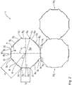
- a coil arrangement 1 comprises several coil modules M, which are 1 are specifically designated M 1 , M 2 and M 3 .
- the coil modules M 1 , M 2 and M 3 are of identical design. If a distinction between the coil modules M 1 , M 2 and M 3 is not important below, they are generally referred to as coil module M. Insofar as a distinction is important below, the coil modules are denoted by M 1 , M 2 and M 3 .
- the coil module M includes a carrier 2 on which a coil 3 is arranged.
- the basic polygonal shape P is therefore an octagon or an octagon.
- the basic polygonal shape P has an R axis.
- the basic polygonal shape P has the same interior angle ⁇ on.
- the basic polygonal shape P has first sides with a first side length L 1 and second sides with a side length L 2 .
- the first side length L 1 is greater than the second side length L 2 .
- the sides with different side lengths L 1 and L 2 are arranged alternately in a direction about the R axis.
- the carrier 2 is plate-shaped.
- the carrier 2 comprises a base plate G with a top side S O , a bottom side S U and side areas S 1 to S N arranged in between.
- the carrier 2 has eight side areas S 1 to S 8 .
- the side areas S 1 to S 8 are straight and flat.
- the carrier 2 comprises first fastening elements B 1 and second fastening elements B 2 in the side regions S 1 to S 8 .
- the first fastening elements B 1 are arranged in the lateral regions S 1 , S 3 , S 5 and S 7
- the second fastening elements B 2 are arranged in the lateral regions S 2 , S 4 , S 6 and S 8 .
- the fasteners B 1 and B 2 are designed differently.
- the fastening elements B 1 are designed as a dovetail-shaped projection, whereas the second fastening elements B 2 are designed as a dovetail-shaped recess.
- the second fasteners B 2 are formed negatively of the first fasteners B 1 .
- the fastening elements B 1 and B 2 are formed in one piece with a base plate G of the carrier 2 . Fasteners B 1 and B 2 are oriented such that mating occurs by movement parallel to axis R .
- the carrier 2 is made of a magnetic material, preferably a ferrite material.
- the ferrite material includes manganese and zinc.
- the carrier 2 has a thickness D in the direction of the axis R. The following applies to the thickness D: 1 mm ⁇ D ⁇ 12 mm.
- the carrier 2 has a maximum across the axis R Dimension A. The following applies to the maximum dimension A: 15 mm ⁇ A ⁇ 200 mm.
- the carrier 2 comprises an outer frame 4 which is arranged on the upper side S o .
- the frame 4 is formed integrally with the base plate G.
- the outer frame 4 is thus formed from a magnetic material such as a ferrite material.
- the frame 4 is shaped according to the basic polygonal shape P and is open in the side area S 1 .
- the coil 3 is arranged inside the outer frame 4 .
- the coil 3 is spirally wound around the axis R.
- the coil 3 essentially has three turns, which are designated in detail as W 1 , W 2 and W 3 .
- the windings W 1 to W 3 are arranged in a common plane.
- the cross section of the coil 3 is preferably between 1 mm 2 and 10 mm 2 .
- Each of the windings W 1 to W 3 is wound polygonally, so that each of the windings W 1 to W 3 forms a number n of straight winding sections w.
- n N.
- the windings W 1 to W 3 have a polygonal shape which corresponds to the basic polygonal shape P.
- the winding sections w run parallel to the side areas S 1 to S 8 or parallel to the sides of the polygonal basic shape P.
- the coil 3 comprises an inner connection A 1 and an outer connection A 2 .
- the inner connection A 1 is connected to the winding W 1 and led out below the windings W 2 , W 3 and the outer connection A 2 .
- Outer terminal A 2 is connected to winding W 3 .
- the terminals A 1 and A 2 are arranged in the side area S 1 .
- the carrier 2 further comprises an inner frame 5 which is arranged on a side of the coil 3 facing the axis R.
- the inner frame 5 is formed integrally with the base plate G .
- the inner frame 5 is thus formed from a magnetic material such as a ferrite material.
- the inner frame 5 has a polygonal shape that corresponds to the basic polygonal shape P.
- the sides of the inner frame 5 run parallel to the sides of the outer frame 4.
- the inner frame 5 is open to the side area S1.
- the spacer elements 6, 7 are formed in one piece with the base plate G and are part of the carrier 2.
- the spacer elements 6, 7 are thus formed from a magnetic material, for example a ferrite material.
- the frames 4, 5 are thus made of a magnetic material, for example a ferrite material.
- the spacer elements 6, 7 have a polygonal shape corresponding to the turns W 1 to W 3 .
- the spacer elements 6, 7 are designed to be open towards the side area S1.
- the coil modules M 1 , M 2 and M 3 are mechanically connected.
- the coil module M 2 is connected to a second fastening element B 2 of the coil module M 1 by means of a first fastening element B 1 .
- the coil module M 2 is connected to a second fastening element B 2 of the coil module M 3 by means of a first fastening element B 1 .
- the coil arrangement 1 has an angular shape. Further coil modules M can be connected in a corresponding manner, so that the coil arrangement 1 can form a desired shape depending on the application, for example the shape of a figure eight.
- connection A 2 of coil module M 1 is connected to connection A 2 of coil module M 2 and connection A 1 of coil module M 2 is connected to connection A 1 of coil module M 3 . This is in 1 illustrated by a dashed line and arrows for the current flow I.
- the coil arrangement 1 Due to the fact that the coil modules M can be connected in a simple and flexible manner to form a coil arrangement 1, the coil arrangement 1 has a high level of efficiency in the wireless electromagnetic energy transmission.
- the coil module M can be manufactured easily and automatically.
- the first fastening elements B 1 are arranged in the lateral areas S 2 , S 4 , S 6 and S 8
- the second fastening elements B 2 are arranged in the lateral areas S 1 , S 3 , S 5 and S 7 .
- the first fastening elements B 1 are designed as dovetail-shaped projections which are arranged on the base body G.
- the second fastening elements B 2 are designed as dovetail-shaped recesses.
- the fastening elements B 1 and B 2 are oriented in such a way that the mechanical connection of two coil modules M takes place by a movement parallel to the upper side S O of the base plate G.
- the side areas S 1 to S 8 have the same length L, so that the basic polygonal shape P is regular.
- the connection A 1 is routed to the outside above the windings W 2 , W 3 .
- first fastening elements B 1 are designed as projections arranged at the bottom, whereas the second fastening elements B 2 are designed as projections arranged at the top.
- the first fastening elements B 1 are arranged laterally on the base plate G, whereas the second fastening elements B 2 are arranged on the upper side S o of the base plate G and on the outer frame 4 and extend laterally outwards.
- the outer frame 4 is open or interrupted in the side areas S 1 , S 3 , S 5 and S 7 .
- a first fastening element B 1 and a second fastening element B 2 of adjacent coil modules M are arranged one above the other so that they overlap.
- Fastening elements B 1 and B 2 are connected to one another in the overlapping area.
- the connection can, for example, be materially bonded by means of an adhesive and/or form-fitting via a profile and a counter-profile.
Landscapes
- Engineering & Computer Science (AREA)
- Power Engineering (AREA)
- Computer Networks & Wireless Communication (AREA)
- Manufacturing & Machinery (AREA)
- Coils Or Transformers For Communication (AREA)
- Coils Of Transformers For General Uses (AREA)
- Manufacturing Cores, Coils, And Magnets (AREA)
Description
- Die Erfindung betrifft ein Spulen-Modul zur Herstellung einer Spulen-Anordnung sowie eine Spulen-Anordnung mit mindestens zwei derartigen Spulen-Modulen. Ferner betrifft die Erfindung ein Verfahren zur Herstellung einer Spulen-Anordnung.
- Aus der
US 9,837,204 B2 - Aus der
CN 109 193 858 A ist eine drahtlose Ladevorrichtung bekannt. Die Ladevorrichtung umfasst einen magnetischen Kern und darauf angeordnete Spulen. Der magnetische Kern umfasst dreieckförmig oder sternförmig angeordnete Stäbe. - Aus der
US 2015/0280442 A1 ist ein induktives Energieübertragungssystem bekannt. Das induktive Energieübertragungssystem umfasst nebeneinander angeordnete Spulenmodule, die jeweils einen hexagonalen Träger mit einer darauf angeordneten Spule umfassen. - Aus der
JP 2013-115200 A - Aus der
US 2019/0304678 A1 ist eine Spuleneinheit mit einem Träger und einer darauf angeordneten Spule bekannt. - Der Erfindung liegt die Aufgabe zugrunde, ein Spulen-Modul zu schaffen, das in einfacher und flexibler Weise die Herstellung einer effizienten Spulen-Anordnung zur drahtlosen elektromagnetischen Energieübertragung ermöglicht.
- Diese Aufgabe wird durch ein Spulen-Modul mit den Merkmalen des Anspruchs 1 gelöst. Das erfindungsgemäße Spulen-Modul ermöglicht aufgrund der polygonalen Grundform des Trägers in einfacher und flexibler Weise die Herstellung einer Spulen-Anordnung aus mehreren SpulenModulen. Aufgrund der polygonalen Grundform können die Träger der Spulen-Module in einfacher und flexibler Weise nebeneinander angeordnet und/oder aneinander befestigt werden. Es gilt vorzugsweise: 6 ≤ N ≤ 10, insbesondere N = 8. Der Träger muss - geometrisch betrachtet - im Wesentlichen die polygonale Grundform haben. Der Träger kann jedoch, beispielsweise aufgrund der Herstellung, abgerundete Ecken und/oder Kanten haben, so dass der Träger geringfügig von einer polygonalen Form abweichen kann. Aufgrund der Drehsymmetrie können die Spulen-Module in einfacher und flexibler Weise zur Herstellung einer Spulen-Anordnung nebeneinander angeordnet werden.
- Zur Erzeugung eines elektromagnetischen Felds ist an dem Träger die Spule angeordnet. Vorzugsweise umfasst das Spulen-Modul genau eine Spule. Die Spule ist vorzugsweise innerhalb der polygonalen Grundform angeordnet. Anders ausgedrückt erstrecken sich die Windungen der Spule nicht seitlich über den Träger hinaus. Zur Herstellung einer Spulen-Anordnung können die Spulen der Spulen-Module einfach und flexibel in Reihe und/oder parallel geschaltet werden. Die elektrischen Eigenschaften der Spulen-Anordnung können hierdurch einfach und flexibel in gewünschter Weise angepasst werden. Dadurch, dass der Träger ein magnetisches Material umfasst, kann das elektromagnetische Feld in einfacher und flexibler Weise geführt und/oder abgeschirmt werden. Vorzugsweise ist das magnetische Material ein Ferritmaterial. Das Ferritmaterial umfasst insbesondere Mangan und Zink. Der Träger ist vorzugsweise aus dem magnetischen Material hergestellt.
- Dadurch, dass zumindest zwei der Seitenbereiche ein jeweiliges Befestigungselement aufweisen, kann der Träger mit weiteren Trägern benachbarter Spulen-Module verbunden werden. Vorzugsweise dienen die Befestigungselemente zur formschlüssigen und/oder reibschlüssigen und/oder stoffschlüssigen Verbindung. Vorzugsweise weist der Träger mindestens ein erstes Befestigungselement und mindestens ein zweites Befestigungselement auf, die unterschiedlich zueinander ausgebildet sind. Vorzugsweise ist das jeweilige zweite Befestigungselement negativ zu dem jeweiligen ersten Befestigungselement geformt. Hierdurch kann ein erstes Befestigungselement eines Trägers mit einem zweiten Befestigungselement eines weiteren Trägers verbunden werden und umgekehrt. Dies ermöglicht eine einfache und flexible Verbindung der Spulen-Module zu einer Spulen-Anordnung.
- Das erfindungsgemäße Spulen-Modul ermöglicht in einfacher Weise die Herstellung von Spulen-Anordnungen mit einer weitgehend beliebigen Form. Aufgrund der Form und/oder der Verschaltung der Spulen-Module kann die jeweilige Spulen-Anordnung flexibel an die gewünschte Anwendung angepasst werden, so dass eine hohe Effizienz bei der drahtlosen elektromagnetischen Energieübertragung erzielbar ist.
- Ein Spulen-Modul nach Anspruch 2 gewährleistet eine einfache und flexible Herstellung einer effizienten Spulen-Anordnung. Vorzugsweise ist die Anzahl N ausgewählt aus der Zahlenmenge 4, 6, 8, 10 und 12. Vorzugsweise ist die Grundform ein Achteck bzw. ein Oktogon mit N = 8.
- Ein Spulen-Modul nach Anspruch 3 gewährleistet eine einfache und flexible Herstellung einer effizienten Spulen-Anordnung. Vorzugsweise ist die Grundform regelmäßig. Eine regelmäßige Grundform bedeutet, dass das Polygon gleichseitig und gleichwinklig ist. Vorzugsweise ist die Grundform ein regelmäßiges Viereck, ein regelmäßiges Sechseck, ein regelmäßiges Achteck, ein regelmäßiges Zehneck oder ein regelmäßiges Zwölfeck.
- Ein Spulen-Modul nach Anspruch 4 gewährleistet eine einfache und flexible Herstellung einer effizienten Spulen-Anordnung. Der Träger ist vorzugsweise eben ausgebildet. Der Träger umfasst eine Oberseite, eine Unterseite und dazwischen ausgebildete Seitenbereiche. Die Anzahl der Seitenbereiche entspricht der Anzahl N. Für eine Dicke D des Trägers gilt vorzugsweise: 1 mm ≤ D ≤ 12 mm, insbesondere 2 mm ≤ D ≤ 10 mm, und insbesondere 3 mm ≤ D ≤ 9 mm. Für eine maximale Abmessung A des Trägers parallel zu der Oberseite und/oder Unterseite gilt vorzugsweise: 15 mm ≤ A ≤ 200 mm, insbesondere 25 mm ≤ A ≤ 150 mm, und insbesondere 35 mm ≤ A ≤ 100 mm.
- Ein Spulen-Modul nach Anspruch 5 gewährleistet eine einfache und flexible Herstellung einer effizienten Spulen-Anordnung. Der Träger umfasst vorzugsweise eine Oberseite und eine Unterseite, zwischen denen die Seitenbereiche angeordnet sind. Die Anzahl der Seitenbereiche entspricht der Anzahl N. Durch die Ausbildung der Seitenbereiche können die Träger von Spulen-Modulen zur Herstellung einer Spulen-Anordnung unmittelbar nebeneinander angeordnet werden. Die Träger können insbesondere Stoß an Stoß angeordnet werden.
- Ein Spulen-Modul nach Anspruch 6 gewährleistet eine einfache und flexible Herstellung einer effizienten Spulen-Anordnung. Der Träger umfasst mindestens ein erstes Befestigungselement und mindestens ein zweites Befestigungselement, die unterschiedlich ausgebildet sind. Die Befestigungselemente dienen zum formschlüssigen und/oder reibschlüssigen und/oder stoffschlüssigen Verbinden mit einem Befestigungselement eines weiteren Trägers. Das zweite Befestigungselement ist vorzugsweise negativ geformt zu dem ersten Befestigungselement. Dies ermöglicht ein formschlüssiges und/oder reibschlüssiges und/oder stoffschlüssiges Verbinden eines ersten Befestigungselements eines ersten Trägers mit einem zweiten Befestigungselement eines zweiten Trägers und umgekehrt. Vorzugsweise sind in den Seitenbereichen in einer Umfangsrichtung abwechselnd erste und zweite Befestigungselemente angeordnet. Die Befestigungselemente ermöglichen eine einfache und flexible Verbindung der Spulen-Module zum Aufbau einer Spulen-Anordnung.
- Ein Spulen-Modul nach Anspruch 7 gewährleistet eine einfache und flexible Herstellung einer effizienten Spulen-Anordnung. Vorzugsweise ist die Spule spiralförmig bzw. spiralartig gewickelt. Spiralförmig bedeutet insbesondere, dass ein Abstand von einer Wickelachse am äußeren Ende einer Windung größer als ein Abstand von der Wickelachse am inneren Anfang der Windung ist. Vorzugsweise liegen alle Windungen der Spule in einer Ebene. Die Spule ist vorzugsweise an einer Oberseite des Trägers angeordnet. Vorzugsweise bildet mindestens eine Windung, insbesondere jede Windung, eine Anzahl n von geraden Windungsabschnitten aus, wobei gilt: n = N. Ist der Träger beispielsweise als Achteck ausgebildet, so ist eine jeweilige Windung der Spule vorzugsweise achteckig und spiralförmig gewickelt. Vorzugsweise sind die geraden Windungsabschnitte parallel zu den geradlinigen und/oder ebenen Seitenbereichen bzw. zu den Seiten der polygonalen Grundform angeordnet.
- Ein Spulen-Modul nach Anspruch 8 gewährleistet eine einfache und flexible Herstellung einer effizienten Spulen-Anordnung. Durch die Ausbildung der mindestens einen Windung, vorzugsweise jeder Windung, wird die von dem Träger vorgegebene Oberfläche zur Anordnung der Spule optimal genutzt. Die geraden Windungsabschnitte der jeweiligen Windung sind insbesondere parallel zu den geradlinigen und/oder ebenen Seitenbereichen des Trägers bzw. zu den Seiten der polygonalen Grundform angeordnet. Die Spule ist vorzugsweise polygonal und spiralförmig gewickelt.
- Ein Spulen-Modul nach Anspruch 9 gewährleistet eine einfache und flexible Herstellung einer effizienten Spulen-Anordnung. Das mindestens eine Abstandselement ermöglicht eine mechanisch und/oder elektrisch getrennte bzw. isolierende Anordnung von benachbarten Windungen der Spule. Vorzugsweise umfasst das mindestens eine Abstandselement ein magnetisches Material, insbesondere ein Ferritmaterial. Beispielsweise ist das mindestens eine Abstandselement aus einem Ferritmaterial hergestellt. Durch das mindestens eine Abstandselement wird insbesondere der Proximity-Effekt reduziert, wodurch der Leitungsquerschnitt der Spule besser genutzt und eine Kopplung bei der drahtlosen elektromagnetischen Energieübertragung verbessert wird. Das mindestens eine Abstandselement ist beispielsweise als Ferritfolie ausgebildet. Die Ferritfolie weist vorzugsweise eine Dicke zwischen 50 µm und 200 µm auf. Eine Höhe des mindestens einen Abstandselements entspricht im Wesentlichen einer Höhe der Spule. Vorzugsweise ist das mindestens eine Abstandselement einteilig mit dem Träger ausgebildet und/oder Teil des Trägers.
- Der Erfindung liegt ferner die Aufgabe zugrunde, eine Spulen-Anordnung zu schaffen, die in einfacher und flexibler Weise für verschiedene Anwendungen eine effiziente drahtlose elektromagnetische Energieübertragung ermöglicht.
- Diese Aufgabe wird durch eine Spulen-Anordnung mit den Merkmalen des Anspruchs 10 gelöst. Vorzugsweise weist die Spulen-Anordnung eine Anzahl K von Spulen-Modulen auf, wobei gilt: 2 ≤ K ≤ 100, insbesondere 6 ≤ K ≤ 80, und insbesondere 10 ≤ K ≤ 60. Vorzugsweise sind bei benachbarten Spulen-Modulen die Träger mechanisch miteinander verbunden und/oder die Spulen elektrisch miteinander verbunden. Die Spulen mehrerer Spulen-Module sind vorzugsweise in Reihe und/oder parallel geschaltet. Die Spulen-Anordnung ist beispielsweise in Form einer Acht aus Spulen-Modulen aufgebaut.
- Der Erfindung liegt ferner die Aufgabe zugrunde, ein Verfahren zu schaffen, das in einfacher und flexibler Weise die Herstellung einer effizienten Spulen-Anordnung zur drahtlosen elektromagnetischen Energieübertragung ermöglicht.
- Diese Aufgabe wird durch ein Verfahren mit den Merkmalen des Anspruchs 11 gelöst. Die Vorteile des erfindungsgemäßen Verfahrens entsprechen den bereits beschriebenen Vorteilen des erfindungsgemäßen Spulen-Moduls und der erfindungsgemäßen Spulen-Anordnung.
- Weitere Merkmale, Vorteile und Einzelheiten ergeben sich aus der nachfolgenden Beschreibung mehrerer Ausführungsbeispiele. Es zeigen:
- Fig. 1
- eine perspektivische Ansicht einer Spulen-Anordnung, die aus mehreren Spulen-Modulen gemäß einem ersten Ausführungsbeispiel aufgebaut ist,
- Fig. 2
- eine Draufsicht auf eine Unterseite der Spulen-Anordnung in
Fig. 1 , - Fig. 3
- eine perspektivische Ansicht eines Spulen-Moduls gemäß einem zweiten Ausführungsbeispiel, und
- Fig. 4
- eine perspektivische Ansicht eines Spulen-Moduls gemäß einem dritten Ausführungsbeispiel.
- Nachfolgend ist anhand der
Fig. 1 und2 ein erstes Ausführungsbeispiel der Erfindung beschrieben. Eine Spulen-Anordnung 1 umfasst mehrere Spulen-Module M, die inFig. 1 im Einzelnen mit M1, M2 und M3 bezeichnet sind. Die Spulen-Module M1, M2 und M3 sind identisch ausgebildet. Sofern es nachfolgend auf eine Unterscheidung der Spulen-Module M1, M2 und M3 nicht ankommt, werden diese allgemein als Spulen-Modul M bezeichnet. Sofern es nachfolgend auf eine Unterscheidung ankommt, so werden die Spulen-Module mit M1, M2 und M3 bezeichnet. - Nachfolgend ist eines der Spulen-Module M im Detail beschrieben. Das Spulen-Modul M umfasst einen Träger 2, an dem eine Spule 3 angeordnet ist. Der Träger 2 hat eine polygonale Grundform P mit einer Anzahl von N Ecken. Die Ecken werden im Einzelnen mit p1 bis pN bezeichnet. Im vorliegenden Ausführungsbeispiel gilt: N = 8. Die polygonale Grundform P ist somit ein Achteck bzw. ein Oktogon.
- Die polygonale Grundform P weist eine Achse R auf. Die polygonale Grundform P ist um die Achse R drehsymmetrisch mit einem Winkel α = 360°·2/N = 90°. Die polygonale Grundform P weist gleiche Innenwinkel β auf. Die polygonale Grundform P hat erste Seiten mit einer ersten Seitenlänge L1 und zweite Seiten mit einer Seitenlänge L2. Die erste Seitenlänge L1 ist größer als die zweite Seitenlänge L2. Die Seiten mit den unterschiedlichen Seitenlängen L1 und L2 sind in einer Richtung um die Achse R abwechselnd angeordnet.
- Der Träger 2 ist plattenförmig ausgebildet. Der Träger 2 umfasst eine Grundplatte G mit einer Oberseite SO, einer Unterseite SU und dazwischen angeordneten Seitenbereiche S1 bis SN. Im vorliegenden Ausführungsbeispiel weist der Träger 2 acht Seitenbereiche S1 bis S8 auf. Die Seitenbereiche S1 bis S8 sind geradlinig und eben ausgebildet. Der Träger 2 umfasst in den Seitenbereichen S1 bis S8 erste Befestigungselemente B1 und zweite Befestigungselemente B2. Die ersten Befestigungselemente B1 sind in den Seitenbereichen S1, S3, S5 und S7 angeordnet, wohingegen die zweiten Befestigungselemente B2 in den Seitenbereichen S2, S4, S6 und S8 angeordnet sind. Die Befestigungselemente B1 und B2 sind unterschiedlich ausgebildet. Die Befestigungselemente B1 sind als schwalbenschwanzförmiger Vorsprung ausgebildet, wohingegen die zweiten Befestigungselemente B2 als schwalbenschwanzförmige Ausnehmung ausgebildet sind. Die zweiten Befestigungselemente B2 sind negativ zu den ersten Befestigungselementen B1 geformt. Die Befestigungselemente B1 und B2 sind einteilig mit einer Grundplatte G des Trägers 2 ausgebildet. Die Befestigungselemente B1 und B2 sind derart orientiert, dass ein Verbinden durch eine Bewegung parallel zu der Achse R erfolgt.
- Der Träger 2 ist aus einem magnetischen Material, vorzugsweise einem Ferritmaterial. Das Ferritmaterial umfasst insbesondere Mangan und Zink. Der Träger 2 hat in Richtung der Achse R eine Dicke D. Für die Dicke D gilt: 1 mm ≤ D ≤ 12 mm. Der Träger 2 hat quer zu der Achse R eine maximale Abmessung A. Für die maximale Abmessung A gilt: 15 mm ≤ A ≤ 200 mm.
- Der Träger 2 umfasst einen äußeren Rahmen 4, der an der Oberseite So angeordnet ist. Der Rahmen 4 ist einteilig mit der Grundplatte G ausgebildet. Der äußere Rahmen 4 ist somit aus einem magnetischen Material, beispielsweise einem Ferritmaterial, ausgebildet. Der Rahmen 4 ist entsprechend der polygonalen Grundform P geformt und in dem Seitenbereich S1 offen ausgebildet.
- Innerhalb des äußeren Rahmens 4 ist die Spule 3 angeordnet. Die Spule 3 ist spiralförmig um die Achse R gewickelt. Die Spule 3 weist im Wesentlichen drei Windungen auf, die im Einzelnen mit W1, W2 und W3 bezeichnet sind. Die Windungen W1 bis W3 sind in einer gemeinsamen Ebene angeordnet. Der Querschnitt der Spule 3 liegt vorzugsweise zwischen 1 mm2 und 10 mm2.
- Jede der Windungen W1 bis W3 ist polygonal gewickelt, so dass jede der Windungen W1 bis W3 eine Anzahl n von geraden Windungsabschnitten w ausbildet. Es gilt: n = N. Dies bedeutet, dass die Windungen W1 bis W3 eine polygonale Form haben, die der polygonalen Grundform P entspricht. Die Windungsabschnitte w verlaufen parallel zu den Seitenbereichen S1 bis S8 bzw. parallel zu den Seiten der polygonalen Grundform P. Die Spule 3 umfasst einen inneren Anschluss A1 und einen äußeren Anschluss A2. Der innere Anschluss A1 ist mit der Windung W1 verbunden und unterhalb der Windungen W2, W3 und des äußeren Anschlusses A2 nach außen geführt. Der äußere Anschluss A2 ist mit der Windung W3 verbunden. Die Anschlüsse A1 und A2 sind in dem Seitenbereich S1 angeordnet.
- Der Träger 2 umfasst ferner einen inneren Rahmen 5, der an einer der Achse R zugewandten Seite der Spule 3 angeordnet ist. Der innere Rahmen 5 ist einteilig mit der Grundplatte G ausgebildet. Der innere Rahmen 5 ist somit aus einem magnetischen Material, beispielsweise einem Ferritmaterial, ausgebildet. Der innere Rahmen 5 hat eine polygonale Form, die der polygonalen Grundform P entspricht. Die Seiten des inneren Rahmens 5 verlaufen parallel zu den Seiten des äußeren Rahmens 4. Der innere Rahmen 5 ist zu dem Seitenbereich S1 hin offen ausgebildet.
- Zwischen den Windungen W1 und W2 sowie den Windungen W2 und W3 ist jeweils ein Abstandselement 6, 7 angeordnet. Die Abstandselemente 6, 7 sind einteilig mit der Grundplatte G ausgebildet und Teil des Trägers 2. Die Abstandselemente 6, 7 sind somit aus einem magnetischen Material, beispielsweise einem Ferritmaterial, ausgebildet. Die Rahmen 4, 5 sind somit aus einem magnetischen Material, beispielsweise einem Ferritmaterial, ausgebildet. Die Abstandselemente 6, 7 haben eine polygonale Form entsprechend den Windungen W1 bis W3. Die Abstandselemente 6, 7 sind zu dem Seitenbereich S1 hin offen ausgebildet.
- Zur Herstellung der Spulen-Anordnung 1 werden die Spulen-Module M1, M2 und M3 mechanisch verbunden. Hierzu wird das Spulen-Modul M2 mittels eines ersten Befestigungselements B1 mit einem zweiten Befestigungselement B2 des Spulen-Moduls M1 verbunden. Weiterhin wird das Spulen-Modul M2 mittels eines ersten Befestigungselements B1 mit einem zweiten Befestigungselement B2 des Spulen-Moduls M3 verbunden. Hierdurch weist die Spule-Anordnung 1 eine Winkelform auf. Weitere SpulenModule M können in entsprechender Weise verbunden werden, so dass die Spulen-Anordnung 1 je nach Anwendung eine gewünschte Form ausbilden kann, beispielsweise die Form einer Acht.
- Die Spulen-Module M1, M2 und M3 werden weiterhin elektrisch miteinander verbunden. Die Spulen 3 der Spulen-Module M1, M2 und M3 werden derart in Reihe geschaltet, dass die Spulen 3 der benachbarten SpulenModule M1 und M2 sowie der benachbarten Spulen-Module M2 und M3 in den jeweiligen mechanischen Verbindungsbereichen in gleichen Richtungen von einem Strom durchfließbar sind. Hierzu ist der Anschluss A2 des Spulen-Moduls M1 mit dem Anschluss A2 des Spulen-Moduls M2 und der Anschluss A1 des Spulen-Moduls M2 mit dem Anschluss A1 des Spulen-Moduls M3 verbunden. Dies ist in
Fig. 1 durch eine gestrichelte Linie und Pfeile für den Stromfluss I veranschaulicht. - Dadurch, dass die Spulen-Module M in einfacher und flexibler Weise zu einer Spulen-Anordnung 1 verbunden werden können, weist die Spulen-Anordnung 1 eine hohe Effizienz bei der drahtlosen elektromagnetischen Energieübertragung auf. Das Spulen-Modul M kann einfach und automatisch hergestellt werden.
- Nachfolgend ist anhand von
Fig. 3 ein zweites Ausführungsbeispiel der Erfindung beschrieben. Im Unterschied zu dem ersten Ausführungsbeispiel sind in den Seitenbereichen S2, S4, S6 und S8 die ersten Befestigungselemente B1 angeordnet, wohingegen in den Seitenbereichen S1, S3, S5 und S7 die zweiten Befestigungselemente B2 angeordnet sind. Die ersten Befestigungselemente B1 sind als schwalbenschwanzförmige Vorsprünge ausgebildet, die an dem Grundkörper G angeordnet sind. Demgegenüber sind die zweiten Befestigungselemente B2 als schwalbenschwanzförmige Ausnehmungen ausgebildet. Die Befestigungselemente B1 und B2 sind derart orientiert, dass das mechanische Verbinden von zwei Spulen-Modulen M durch eine Bewegung parallel zu der Oberseite SO der Grundplatte G erfolgt. Die Seitenbereiche S1 bis S8 haben eine gleiche Länge L, so dass die polygonale Grundform P regelmäßig ist. Der Anschluss A1 ist oberhalb der Windungen W2, W3 nach außen geführt. Hinsichtlich des weiteren Aufbaus und der weiten Funktionsweise des Spulen-Moduls M wird auf das vorangegangene Ausführungsbeispiel verwiesen. - Nachfolgend ist anhand von
Fig. 4 ein drittes Ausführungsbeispiel der Erfindung beschrieben. Im Unterschied zu den vorangegangenen Ausführungsbeispielen sind die ersten Befestigungselemente B1 als unten angeordnete Vorsprünge ausgebildet, wohingegen die zweiten Befestigungselemente B2 als oben angeordnete Vorsprünge ausgebildet sind. Die ersten Befestigungselemente B1 sind seitlich an der Grundplatte G angeordnet, wohingegen die zweiten Befestigungselemente B2 an der Oberseite So der Grundplatte G und an dem äußeren Rahmen 4 angeordnet sind und sich seitlich nach außen erstrecken. Der äußere Rahmen 4 ist in den Seitenbereichen S1, S3, S5 und S7 offen ausgebildet bzw. unterbrochen. Zum mechanischen Verbinden wird ein erstes Befestigungselement B1 und ein zweites Befestigungselement B2 benachbarter Spulen-Module M übereinander angeordnet, so dass diese überlappen. Im Überlappungsbereich werden die Befestigungselemente B1 und B2 miteinander verbunden. Die Verbindung kann beispielsweise stoffschlüssig mittels eines Klebstoffs und/oder formschlüssig über ein Profil und ein Gegenprofil erfolgen. Hinsichtlich des weiteren Aufbaus und der weiteren Funktionsweise des Spulen-Moduls M wird auf die vorangegangenen Ausführungsbeispiele verwiesen.
Claims (11)
- Spulen-Modul (M) zur Herstellung einer Spulen-Anordnung mit- einem Träger (2),-- der eine polygonale Grundform (P) mit einer Anzahl N von Ecken (p1 bis pN) hat, wobei gilt: 4 ≤ N ≤ 12, und wobei die polygonale Grundform (P) drehsymmetrisch mit einem Winkel von 360°·2/N ist,-- der ein magnetisches Material umfasst,- einer an dem Träger (2) angeordneten Spule (3), wobei der Träger (2) Seitenbereiche (S1 bis SN) umfasst, dadurch gekennzeichnet, dass in zumindest zwei der Seitenbereiche (S1 bis SN) ein jeweiliges Befestigungselement (B1, B2) angeordnet ist.
- Spulen-Modul nach Anspruch 1, dadurch gekennzeichnet, dass die Anzahl N der Ecken (p1 bis pN) gerade ist.
- Spulen-Modul nach Anspruch 1 oder 2, dadurch gekennzeichnet, dass die polygonale Grundform (P) drehsymmetrisch mit einem Winkel von 360°/N ist.
- Spulen-Modul nach mindestens einem der vorangegangenen Ansprüche, dadurch gekennzeichnet, dass der Träger (2) plattenförmig ist.
- Spulen-Modul nach mindestens einem der vorangegangenen Ansprüche, dadurch gekennzeichnet,
dass der Träger (2) Seitenbereiche (S1 bis SN) umfasst, die zumindest abschnittsweise geradlinig und/oder eben ausgebildet sind. - Spulen-Modul nach mindestens einem der vorangegangenen Ansprüche, dadurch gekennzeichnet,
dass in den Seitenbereichen (S1 bis SN) zumindest zwei unterschiedliche Befestigungselemente (B1, B2) angeordnet sind. - Spulen-Modul nach mindestens einem der vorangegangenen Ansprüche, dadurch gekennzeichnet,
dass die Spule (3) mindestens zwei Windungen (W1 bis W3) umfasst, die in einer Ebene angeordnet sind. - Spulen-Modul nach mindestens einem der vorangegangenen Ansprüche, dadurch gekennzeichnet,
dass die Spule (3) mindestens eine Windung (W1 bis W3) umfasst, die eine Anzahl n von geraden Windungsabschnitten (w) ausbildet, wobei gilt: n = N. - Spulen-Modul nach mindestens einem der vorangegangenen Ansprüche, dadurch gekennzeichnet,
dass zwischen zwei benachbarten Windungen (W1 bis W3) der Spule (3) mindestens ein Abstandselement (6, 7) angeordnet ist, das insbesondere ein magnetisches Material umfasst. - Spulen-Anordnung zur drahtlosen elektromagnetischen Energieübertragung mit mindestens zwei Spulen-Modulen (M) nach mindestens einem der Ansprüche 1 bis 9, wobei die Spulen (3) der Spulenmodule elektrisch verbunden sind und/oder die Träger (2) der Spulenmodule mechanisch verbunden sind.
- Verfahren zur Herstellung einer Spulen-Anordnung, umfassend die Schritte:- Bereitstellen von mindestens zwei Spulen-Modulen (M) nach mindestens einem der Ansprüche 1 bis 9, und- elektrisches Verbinden der Spulen (3) und/oder mechanisches Verbinden der Träger (2) der mindestens zwei Spulen-Module (M).
Applications Claiming Priority (2)
| Application Number | Priority Date | Filing Date | Title |
|---|---|---|---|
| DE102020201753.0A DE102020201753A1 (de) | 2020-02-12 | 2020-02-12 | Spulen-Modul und Verfahren zur Herstellung einer Spulen-Anordnung |
| PCT/EP2021/052650 WO2021160508A1 (de) | 2020-02-12 | 2021-02-04 | Spulen-modul und verfahren zur herstellung einer spulen-anordnung |
Publications (2)
| Publication Number | Publication Date |
|---|---|
| EP3956909A1 EP3956909A1 (de) | 2022-02-23 |
| EP3956909B1 true EP3956909B1 (de) | 2022-07-13 |
Family
ID=74556914
Family Applications (1)
| Application Number | Title | Priority Date | Filing Date |
|---|---|---|---|
| EP21703671.4A Active EP3956909B1 (de) | 2020-02-12 | 2021-02-04 | Spulen-modul und verfahren zur herstellung einer spulen-anordnung |
Country Status (8)
| Country | Link |
|---|---|
| US (1) | US20230059428A1 (de) |
| EP (1) | EP3956909B1 (de) |
| JP (1) | JP7683988B2 (de) |
| KR (1) | KR102836951B1 (de) |
| CN (1) | CN115136262A (de) |
| DE (1) | DE102020201753A1 (de) |
| ES (1) | ES2927371T3 (de) |
| WO (1) | WO2021160508A1 (de) |
Families Citing this family (1)
| Publication number | Priority date | Publication date | Assignee | Title |
|---|---|---|---|---|
| CN116598124B (zh) * | 2023-06-02 | 2026-02-03 | 东莞市德弗力五金电子材料有限公司 | 一种生产线圈模组的辅助定位装置及其使用方法 |
Family Cites Families (14)
| Publication number | Priority date | Publication date | Assignee | Title |
|---|---|---|---|---|
| US7414347B2 (en) * | 2004-03-23 | 2008-08-19 | Emerson Electric Co. | End cap for segmented stator |
| JP4209437B2 (ja) * | 2006-11-10 | 2009-01-14 | 三菱重工業株式会社 | 移動体の非接触給電装置及びその保護装置 |
| CN102906832B (zh) * | 2010-05-28 | 2017-06-09 | 皇家飞利浦电子股份有限公司 | 用于在模块化电力传输系统中使用的发射器模块 |
| JP5945862B2 (ja) | 2011-11-28 | 2016-07-05 | パナソニックIpマネジメント株式会社 | 非接触給電装置 |
| JP5906457B2 (ja) * | 2011-12-05 | 2016-04-20 | パナソニックIpマネジメント株式会社 | 非接触給電装置 |
| JP2013214613A (ja) | 2012-04-02 | 2013-10-17 | Panasonic Corp | コイルユニット及びコイルユニットを備える電力伝送装置 |
| US9837204B2 (en) | 2013-12-17 | 2017-12-05 | Qualcomm Incorporated | Coil topologies for inductive power transfer |
| US9601933B2 (en) * | 2014-03-25 | 2017-03-21 | Apple Inc. | Tessellated inductive power transmission system coil configurations |
| JP6519773B2 (ja) | 2014-05-22 | 2019-05-29 | 株式会社デンソー | 電力伝送用パッドおよび非接触電力伝送システム |
| US10027147B2 (en) * | 2015-01-23 | 2018-07-17 | Qualcomm Incorporated | Methods and apparatus for a modular coil holder for an extended wireless charging roadway assembly |
| DE102015202032A1 (de) * | 2015-02-05 | 2016-08-11 | Würth Elektronik eiSos Gmbh & Co. KG | Induktor, insbesondere zur magnetisch gekoppelten Energieübertragung, sowie Verfahren zum Betreiben eines derartigen Induktors |
| CN107833729A (zh) | 2017-11-01 | 2018-03-23 | 国家电网公司 | 六角地砖型线圈模块及阵列线圈 |
| JP7106943B2 (ja) | 2018-03-30 | 2022-07-27 | Tdk株式会社 | コイルユニット、ワイヤレス送電装置、ワイヤレス受電装置、ワイヤレス電力伝送システム |
| CN109193858B (zh) | 2018-10-24 | 2021-12-21 | 哈尔滨工业大学(威海) | 无线充电装置及无人机无线充电系统 |
-
2020
- 2020-02-12 DE DE102020201753.0A patent/DE102020201753A1/de active Pending
-
2021
- 2021-02-04 EP EP21703671.4A patent/EP3956909B1/de active Active
- 2021-02-04 KR KR1020227027845A patent/KR102836951B1/ko active Active
- 2021-02-04 JP JP2022547968A patent/JP7683988B2/ja active Active
- 2021-02-04 CN CN202180014446.8A patent/CN115136262A/zh active Pending
- 2021-02-04 ES ES21703671T patent/ES2927371T3/es active Active
- 2021-02-04 US US17/792,303 patent/US20230059428A1/en active Pending
- 2021-02-04 WO PCT/EP2021/052650 patent/WO2021160508A1/de not_active Ceased
Also Published As
| Publication number | Publication date |
|---|---|
| EP3956909A1 (de) | 2022-02-23 |
| ES2927371T3 (es) | 2022-11-04 |
| WO2021160508A1 (de) | 2021-08-19 |
| KR20220136368A (ko) | 2022-10-07 |
| KR102836951B1 (ko) | 2025-07-21 |
| JP7683988B2 (ja) | 2025-05-27 |
| CN115136262A (zh) | 2022-09-30 |
| DE102020201753A1 (de) | 2021-08-12 |
| JP2023512810A (ja) | 2023-03-29 |
| US20230059428A1 (en) | 2023-02-23 |
Similar Documents
| Publication | Publication Date | Title |
|---|---|---|
| DE4128931C2 (de) | Ablenkspule in einem Elektromagneten und ein Verfahren zu ihrer Herstellung | |
| DE102004025105A1 (de) | Stator und isolierender Spulenkörper und Herstellungsverfahren für den Stator | |
| DE102017218966A1 (de) | Induktorkomponente | |
| DE112015002145T5 (de) | Drossel | |
| WO2013041353A2 (de) | Elektromotor | |
| DE102020101149A1 (de) | Axialflussmaschine mit mechanisch fixierten Statorkernen mit radial verlaufenden Blechsegmenten | |
| DE112017004402T5 (de) | Stator, statorherstellungsverfahren und motor | |
| DE102019123434A1 (de) | Blechring für ein Rotorblechpaket eines Rotors einer elektrischen Maschine und Verfahren zur Herstellung eines Rotorblechpakets aus mehreren Blechringen | |
| EP3956909B1 (de) | Spulen-modul und verfahren zur herstellung einer spulen-anordnung | |
| DE3014943A1 (de) | Spulenelement fuer einen elektromotor und verfahren zur herstellung des spulenelementes | |
| DE102023129344A1 (de) | Spulenbauteil | |
| DE102023107335A1 (de) | Spulendraht, herstellungsverfahren für spulendraht, stator und elektromotor | |
| DE10239730A1 (de) | Ständer für elektrische Drehfeldmaschinen | |
| DE102007030980A1 (de) | Stator für einen elektrischen Antriebsmotor | |
| DE102022133053A1 (de) | Endfaser für stator und verfahren zur bildung von leitern | |
| DE102008040146A1 (de) | Zündspule | |
| WO2014048726A1 (de) | Vorrichtung zum kühlen | |
| DE102017208150A1 (de) | Elektromotor | |
| EP3707736B1 (de) | Transformator zur verwendung in einem schienenfahrzeug | |
| DE112018003428T5 (de) | Wicklung | |
| EP2771893B1 (de) | Mehrphasen-induktivitätenmodul | |
| DE102019102654A1 (de) | Sekundärspulentopologie | |
| DE102016203350A1 (de) | Spule | |
| DE102017206440A1 (de) | Spule mit einer Flachleitung | |
| DE112024001548T5 (de) | Induktive Spulenanordnung und Verfahren zu deren Herstellung |
Legal Events
| Date | Code | Title | Description |
|---|---|---|---|
| STAA | Information on the status of an ep patent application or granted ep patent |
Free format text: STATUS: UNKNOWN |
|
| STAA | Information on the status of an ep patent application or granted ep patent |
Free format text: STATUS: THE INTERNATIONAL PUBLICATION HAS BEEN MADE |
|
| PUAI | Public reference made under article 153(3) epc to a published international application that has entered the european phase |
Free format text: ORIGINAL CODE: 0009012 |
|
| STAA | Information on the status of an ep patent application or granted ep patent |
Free format text: STATUS: REQUEST FOR EXAMINATION WAS MADE |
|
| 17P | Request for examination filed |
Effective date: 20211115 |
|
| AK | Designated contracting states |
Kind code of ref document: A1 Designated state(s): AL AT BE BG CH CY CZ DE DK EE ES FI FR GB GR HR HU IE IS IT LI LT LU LV MC MK MT NL NO PL PT RO RS SE SI SK SM TR |
|
| GRAP | Despatch of communication of intention to grant a patent |
Free format text: ORIGINAL CODE: EPIDOSNIGR1 |
|
| STAA | Information on the status of an ep patent application or granted ep patent |
Free format text: STATUS: GRANT OF PATENT IS INTENDED |
|
| INTG | Intention to grant announced |
Effective date: 20220405 |
|
| GRAS | Grant fee paid |
Free format text: ORIGINAL CODE: EPIDOSNIGR3 |
|
| GRAA | (expected) grant |
Free format text: ORIGINAL CODE: 0009210 |
|
| STAA | Information on the status of an ep patent application or granted ep patent |
Free format text: STATUS: THE PATENT HAS BEEN GRANTED |
|
| AK | Designated contracting states |
Kind code of ref document: B1 Designated state(s): AL AT BE BG CH CY CZ DE DK EE ES FI FR GB GR HR HU IE IS IT LI LT LU LV MC MK MT NL NO PL PT RO RS SE SI SK SM TR |
|
| DAV | Request for validation of the european patent (deleted) | ||
| DAX | Request for extension of the european patent (deleted) | ||
| REG | Reference to a national code |
Ref country code: CH Ref legal event code: EP |
|
| REG | Reference to a national code |
Ref country code: DE Ref legal event code: R096 Ref document number: 502021000071 Country of ref document: DE |
|
| REG | Reference to a national code |
Ref country code: AT Ref legal event code: REF Ref document number: 1504693 Country of ref document: AT Kind code of ref document: T Effective date: 20220815 |
|
| REG | Reference to a national code |
Ref country code: IE Ref legal event code: FG4D Free format text: LANGUAGE OF EP DOCUMENT: GERMAN |
|
| REG | Reference to a national code |
Ref country code: ES Ref legal event code: FG2A Ref document number: 2927371 Country of ref document: ES Kind code of ref document: T3 Effective date: 20221104 |
|
| REG | Reference to a national code |
Ref country code: LT Ref legal event code: MG9D |
|
| REG | Reference to a national code |
Ref country code: NL Ref legal event code: MP Effective date: 20220713 |
|
| PG25 | Lapsed in a contracting state [announced via postgrant information from national office to epo] |
Ref country code: SE Free format text: LAPSE BECAUSE OF FAILURE TO SUBMIT A TRANSLATION OF THE DESCRIPTION OR TO PAY THE FEE WITHIN THE PRESCRIBED TIME-LIMIT Effective date: 20220713 Ref country code: RS Free format text: LAPSE BECAUSE OF FAILURE TO SUBMIT A TRANSLATION OF THE DESCRIPTION OR TO PAY THE FEE WITHIN THE PRESCRIBED TIME-LIMIT Effective date: 20220713 Ref country code: PT Free format text: LAPSE BECAUSE OF FAILURE TO SUBMIT A TRANSLATION OF THE DESCRIPTION OR TO PAY THE FEE WITHIN THE PRESCRIBED TIME-LIMIT Effective date: 20221114 Ref country code: NO Free format text: LAPSE BECAUSE OF FAILURE TO SUBMIT A TRANSLATION OF THE DESCRIPTION OR TO PAY THE FEE WITHIN THE PRESCRIBED TIME-LIMIT Effective date: 20221013 Ref country code: NL Free format text: LAPSE BECAUSE OF FAILURE TO SUBMIT A TRANSLATION OF THE DESCRIPTION OR TO PAY THE FEE WITHIN THE PRESCRIBED TIME-LIMIT Effective date: 20220713 Ref country code: LV Free format text: LAPSE BECAUSE OF FAILURE TO SUBMIT A TRANSLATION OF THE DESCRIPTION OR TO PAY THE FEE WITHIN THE PRESCRIBED TIME-LIMIT Effective date: 20220713 Ref country code: LT Free format text: LAPSE BECAUSE OF FAILURE TO SUBMIT A TRANSLATION OF THE DESCRIPTION OR TO PAY THE FEE WITHIN THE PRESCRIBED TIME-LIMIT Effective date: 20220713 Ref country code: FI Free format text: LAPSE BECAUSE OF FAILURE TO SUBMIT A TRANSLATION OF THE DESCRIPTION OR TO PAY THE FEE WITHIN THE PRESCRIBED TIME-LIMIT Effective date: 20220713 |
|
| PG25 | Lapsed in a contracting state [announced via postgrant information from national office to epo] |
Ref country code: PL Free format text: LAPSE BECAUSE OF FAILURE TO SUBMIT A TRANSLATION OF THE DESCRIPTION OR TO PAY THE FEE WITHIN THE PRESCRIBED TIME-LIMIT Effective date: 20220713 Ref country code: IS Free format text: LAPSE BECAUSE OF FAILURE TO SUBMIT A TRANSLATION OF THE DESCRIPTION OR TO PAY THE FEE WITHIN THE PRESCRIBED TIME-LIMIT Effective date: 20221113 Ref country code: HR Free format text: LAPSE BECAUSE OF FAILURE TO SUBMIT A TRANSLATION OF THE DESCRIPTION OR TO PAY THE FEE WITHIN THE PRESCRIBED TIME-LIMIT Effective date: 20220713 Ref country code: GR Free format text: LAPSE BECAUSE OF FAILURE TO SUBMIT A TRANSLATION OF THE DESCRIPTION OR TO PAY THE FEE WITHIN THE PRESCRIBED TIME-LIMIT Effective date: 20221014 |
|
| REG | Reference to a national code |
Ref country code: DE Ref legal event code: R097 Ref document number: 502021000071 Country of ref document: DE |
|
| PG25 | Lapsed in a contracting state [announced via postgrant information from national office to epo] |
Ref country code: SM Free format text: LAPSE BECAUSE OF FAILURE TO SUBMIT A TRANSLATION OF THE DESCRIPTION OR TO PAY THE FEE WITHIN THE PRESCRIBED TIME-LIMIT Effective date: 20220713 Ref country code: RO Free format text: LAPSE BECAUSE OF FAILURE TO SUBMIT A TRANSLATION OF THE DESCRIPTION OR TO PAY THE FEE WITHIN THE PRESCRIBED TIME-LIMIT Effective date: 20220713 Ref country code: DK Free format text: LAPSE BECAUSE OF FAILURE TO SUBMIT A TRANSLATION OF THE DESCRIPTION OR TO PAY THE FEE WITHIN THE PRESCRIBED TIME-LIMIT Effective date: 20220713 Ref country code: CZ Free format text: LAPSE BECAUSE OF FAILURE TO SUBMIT A TRANSLATION OF THE DESCRIPTION OR TO PAY THE FEE WITHIN THE PRESCRIBED TIME-LIMIT Effective date: 20220713 |
|
| PLBE | No opposition filed within time limit |
Free format text: ORIGINAL CODE: 0009261 |
|
| STAA | Information on the status of an ep patent application or granted ep patent |
Free format text: STATUS: NO OPPOSITION FILED WITHIN TIME LIMIT |
|
| PG25 | Lapsed in a contracting state [announced via postgrant information from national office to epo] |
Ref country code: SK Free format text: LAPSE BECAUSE OF FAILURE TO SUBMIT A TRANSLATION OF THE DESCRIPTION OR TO PAY THE FEE WITHIN THE PRESCRIBED TIME-LIMIT Effective date: 20220713 Ref country code: EE Free format text: LAPSE BECAUSE OF FAILURE TO SUBMIT A TRANSLATION OF THE DESCRIPTION OR TO PAY THE FEE WITHIN THE PRESCRIBED TIME-LIMIT Effective date: 20220713 |
|
| 26N | No opposition filed |
Effective date: 20230414 |
|
| P01 | Opt-out of the competence of the unified patent court (upc) registered |
Effective date: 20230517 |
|
| PG25 | Lapsed in a contracting state [announced via postgrant information from national office to epo] |
Ref country code: AL Free format text: LAPSE BECAUSE OF FAILURE TO SUBMIT A TRANSLATION OF THE DESCRIPTION OR TO PAY THE FEE WITHIN THE PRESCRIBED TIME-LIMIT Effective date: 20220713 |
|
| PG25 | Lapsed in a contracting state [announced via postgrant information from national office to epo] |
Ref country code: MC Free format text: LAPSE BECAUSE OF FAILURE TO SUBMIT A TRANSLATION OF THE DESCRIPTION OR TO PAY THE FEE WITHIN THE PRESCRIBED TIME-LIMIT Effective date: 20220713 |
|
| PG25 | Lapsed in a contracting state [announced via postgrant information from national office to epo] |
Ref country code: LU Free format text: LAPSE BECAUSE OF NON-PAYMENT OF DUE FEES Effective date: 20230204 |
|
| REG | Reference to a national code |
Ref country code: IE Ref legal event code: MM4A |
|
| PG25 | Lapsed in a contracting state [announced via postgrant information from national office to epo] |
Ref country code: IE Free format text: LAPSE BECAUSE OF NON-PAYMENT OF DUE FEES Effective date: 20230204 |
|
| PG25 | Lapsed in a contracting state [announced via postgrant information from national office to epo] |
Ref country code: BG Free format text: LAPSE BECAUSE OF FAILURE TO SUBMIT A TRANSLATION OF THE DESCRIPTION OR TO PAY THE FEE WITHIN THE PRESCRIBED TIME-LIMIT Effective date: 20220713 |
|
| PG25 | Lapsed in a contracting state [announced via postgrant information from national office to epo] |
Ref country code: BG Free format text: LAPSE BECAUSE OF FAILURE TO SUBMIT A TRANSLATION OF THE DESCRIPTION OR TO PAY THE FEE WITHIN THE PRESCRIBED TIME-LIMIT Effective date: 20220713 |
|
| PGFP | Annual fee paid to national office [announced via postgrant information from national office to epo] |
Ref country code: ES Payment date: 20250331 Year of fee payment: 5 |
|
| PG25 | Lapsed in a contracting state [announced via postgrant information from national office to epo] |
Ref country code: CY Free format text: LAPSE BECAUSE OF FAILURE TO SUBMIT A TRANSLATION OF THE DESCRIPTION OR TO PAY THE FEE WITHIN THE PRESCRIBED TIME-LIMIT; INVALID AB INITIO Effective date: 20210204 |
|
| PG25 | Lapsed in a contracting state [announced via postgrant information from national office to epo] |
Ref country code: HU Free format text: LAPSE BECAUSE OF FAILURE TO SUBMIT A TRANSLATION OF THE DESCRIPTION OR TO PAY THE FEE WITHIN THE PRESCRIBED TIME-LIMIT; INVALID AB INITIO Effective date: 20210204 |
|
| PG25 | Lapsed in a contracting state [announced via postgrant information from national office to epo] |
Ref country code: TR Free format text: LAPSE BECAUSE OF FAILURE TO SUBMIT A TRANSLATION OF THE DESCRIPTION OR TO PAY THE FEE WITHIN THE PRESCRIBED TIME-LIMIT Effective date: 20220713 |
|
| PG25 | Lapsed in a contracting state [announced via postgrant information from national office to epo] |
Ref country code: SI Free format text: LAPSE BECAUSE OF FAILURE TO SUBMIT A TRANSLATION OF THE DESCRIPTION OR TO PAY THE FEE WITHIN THE PRESCRIBED TIME-LIMIT Effective date: 20220713 |
|
| REG | Reference to a national code |
Ref country code: CH Ref legal event code: U11 Free format text: ST27 STATUS EVENT CODE: U-0-0-U10-U11 (AS PROVIDED BY THE NATIONAL OFFICE) Effective date: 20260301 |
|
| PGFP | Annual fee paid to national office [announced via postgrant information from national office to epo] |
Ref country code: GB Payment date: 20260220 Year of fee payment: 6 |
|
| PGFP | Annual fee paid to national office [announced via postgrant information from national office to epo] |
Ref country code: DE Payment date: 20260218 Year of fee payment: 6 |
|
| PGFP | Annual fee paid to national office [announced via postgrant information from national office to epo] |
Ref country code: AT Payment date: 20260219 Year of fee payment: 6 |
|
| PGFP | Annual fee paid to national office [announced via postgrant information from national office to epo] |
Ref country code: BE Payment date: 20260218 Year of fee payment: 6 Ref country code: IT Payment date: 20260224 Year of fee payment: 6 |
|
| PGFP | Annual fee paid to national office [announced via postgrant information from national office to epo] |
Ref country code: FR Payment date: 20260219 Year of fee payment: 6 |
|
| PGFP | Annual fee paid to national office [announced via postgrant information from national office to epo] |
Ref country code: CH Payment date: 20260301 Year of fee payment: 6 |