EP3956165B1 - Schalteinrichtung für ein hybrides antriebssystem eines kraftfahrzeuges; antriebssystem sowie kraftfahrzeug - Google Patents
Schalteinrichtung für ein hybrides antriebssystem eines kraftfahrzeuges; antriebssystem sowie kraftfahrzeug Download PDFInfo
- Publication number
- EP3956165B1 EP3956165B1 EP20716387.4A EP20716387A EP3956165B1 EP 3956165 B1 EP3956165 B1 EP 3956165B1 EP 20716387 A EP20716387 A EP 20716387A EP 3956165 B1 EP3956165 B1 EP 3956165B1
- Authority
- EP
- European Patent Office
- Prior art keywords
- shaft
- gearwheel
- rotationally
- motor
- sliding sleeve
- Prior art date
- Legal status (The legal status is an assumption and is not a legal conclusion. Google has not performed a legal analysis and makes no representation as to the accuracy of the status listed.)
- Active
Links
Images


Classifications
-
- B—PERFORMING OPERATIONS; TRANSPORTING
- B60—VEHICLES IN GENERAL
- B60K—ARRANGEMENT OR MOUNTING OF PROPULSION UNITS OR OF TRANSMISSIONS IN VEHICLES; ARRANGEMENT OR MOUNTING OF PLURAL DIVERSE PRIME-MOVERS IN VEHICLES; AUXILIARY DRIVES FOR VEHICLES; INSTRUMENTATION OR DASHBOARDS FOR VEHICLES; ARRANGEMENTS IN CONNECTION WITH COOLING, AIR INTAKE, GAS EXHAUST OR FUEL SUPPLY OF PROPULSION UNITS IN VEHICLES
- B60K6/00—Arrangement or mounting of plural diverse prime-movers for mutual or common propulsion, e.g. hybrid propulsion systems comprising electric motors and internal combustion engines
- B60K6/20—Arrangement or mounting of plural diverse prime-movers for mutual or common propulsion, e.g. hybrid propulsion systems comprising electric motors and internal combustion engines the prime-movers consisting of electric motors and internal combustion engines, e.g. HEVs
- B60K6/22—Arrangement or mounting of plural diverse prime-movers for mutual or common propulsion, e.g. hybrid propulsion systems comprising electric motors and internal combustion engines the prime-movers consisting of electric motors and internal combustion engines, e.g. HEVs characterised by apparatus, components or means specially adapted for HEVs
- B60K6/36—Arrangement or mounting of plural diverse prime-movers for mutual or common propulsion, e.g. hybrid propulsion systems comprising electric motors and internal combustion engines the prime-movers consisting of electric motors and internal combustion engines, e.g. HEVs characterised by apparatus, components or means specially adapted for HEVs characterised by the transmission gearings
- B60K6/365—Arrangement or mounting of plural diverse prime-movers for mutual or common propulsion, e.g. hybrid propulsion systems comprising electric motors and internal combustion engines the prime-movers consisting of electric motors and internal combustion engines, e.g. HEVs characterised by apparatus, components or means specially adapted for HEVs characterised by the transmission gearings with the gears having orbital motion
-
- B—PERFORMING OPERATIONS; TRANSPORTING
- B60—VEHICLES IN GENERAL
- B60K—ARRANGEMENT OR MOUNTING OF PROPULSION UNITS OR OF TRANSMISSIONS IN VEHICLES; ARRANGEMENT OR MOUNTING OF PLURAL DIVERSE PRIME-MOVERS IN VEHICLES; AUXILIARY DRIVES FOR VEHICLES; INSTRUMENTATION OR DASHBOARDS FOR VEHICLES; ARRANGEMENTS IN CONNECTION WITH COOLING, AIR INTAKE, GAS EXHAUST OR FUEL SUPPLY OF PROPULSION UNITS IN VEHICLES
- B60K20/00—Arrangement or mounting of change-speed gearing control devices in vehicles
- B60K20/02—Arrangement or mounting of change-speed gearing control devices in vehicles of initiating means
-
- B—PERFORMING OPERATIONS; TRANSPORTING
- B60—VEHICLES IN GENERAL
- B60K—ARRANGEMENT OR MOUNTING OF PROPULSION UNITS OR OF TRANSMISSIONS IN VEHICLES; ARRANGEMENT OR MOUNTING OF PLURAL DIVERSE PRIME-MOVERS IN VEHICLES; AUXILIARY DRIVES FOR VEHICLES; INSTRUMENTATION OR DASHBOARDS FOR VEHICLES; ARRANGEMENTS IN CONNECTION WITH COOLING, AIR INTAKE, GAS EXHAUST OR FUEL SUPPLY OF PROPULSION UNITS IN VEHICLES
- B60K6/00—Arrangement or mounting of plural diverse prime-movers for mutual or common propulsion, e.g. hybrid propulsion systems comprising electric motors and internal combustion engines
- B60K6/20—Arrangement or mounting of plural diverse prime-movers for mutual or common propulsion, e.g. hybrid propulsion systems comprising electric motors and internal combustion engines the prime-movers consisting of electric motors and internal combustion engines, e.g. HEVs
- B60K6/22—Arrangement or mounting of plural diverse prime-movers for mutual or common propulsion, e.g. hybrid propulsion systems comprising electric motors and internal combustion engines the prime-movers consisting of electric motors and internal combustion engines, e.g. HEVs characterised by apparatus, components or means specially adapted for HEVs
- B60K6/38—Arrangement or mounting of plural diverse prime-movers for mutual or common propulsion, e.g. hybrid propulsion systems comprising electric motors and internal combustion engines the prime-movers consisting of electric motors and internal combustion engines, e.g. HEVs characterised by apparatus, components or means specially adapted for HEVs characterised by the driveline clutches
- B60K6/387—Actuated clutches, i.e. clutches engaged or disengaged by electric, hydraulic or mechanical actuating means
-
- B—PERFORMING OPERATIONS; TRANSPORTING
- B60—VEHICLES IN GENERAL
- B60K—ARRANGEMENT OR MOUNTING OF PROPULSION UNITS OR OF TRANSMISSIONS IN VEHICLES; ARRANGEMENT OR MOUNTING OF PLURAL DIVERSE PRIME-MOVERS IN VEHICLES; AUXILIARY DRIVES FOR VEHICLES; INSTRUMENTATION OR DASHBOARDS FOR VEHICLES; ARRANGEMENTS IN CONNECTION WITH COOLING, AIR INTAKE, GAS EXHAUST OR FUEL SUPPLY OF PROPULSION UNITS IN VEHICLES
- B60K6/00—Arrangement or mounting of plural diverse prime-movers for mutual or common propulsion, e.g. hybrid propulsion systems comprising electric motors and internal combustion engines
- B60K6/20—Arrangement or mounting of plural diverse prime-movers for mutual or common propulsion, e.g. hybrid propulsion systems comprising electric motors and internal combustion engines the prime-movers consisting of electric motors and internal combustion engines, e.g. HEVs
- B60K6/42—Arrangement or mounting of plural diverse prime-movers for mutual or common propulsion, e.g. hybrid propulsion systems comprising electric motors and internal combustion engines the prime-movers consisting of electric motors and internal combustion engines, e.g. HEVs characterised by the architecture of the hybrid electric vehicle
- B60K6/44—Series-parallel type
- B60K6/442—Series-parallel switching type
-
- B—PERFORMING OPERATIONS; TRANSPORTING
- B60—VEHICLES IN GENERAL
- B60W—CONJOINT CONTROL OF VEHICLE SUB-UNITS OF DIFFERENT TYPE OR DIFFERENT FUNCTION; CONTROL SYSTEMS SPECIALLY ADAPTED FOR HYBRID VEHICLES; ROAD VEHICLE DRIVE CONTROL SYSTEMS FOR PURPOSES NOT RELATED TO THE CONTROL OF A PARTICULAR SUB-UNIT
- B60W10/00—Conjoint control of vehicle sub-units of different type or different function
- B60W10/02—Conjoint control of vehicle sub-units of different type or different function including control of driveline clutches
-
- B—PERFORMING OPERATIONS; TRANSPORTING
- B60—VEHICLES IN GENERAL
- B60W—CONJOINT CONTROL OF VEHICLE SUB-UNITS OF DIFFERENT TYPE OR DIFFERENT FUNCTION; CONTROL SYSTEMS SPECIALLY ADAPTED FOR HYBRID VEHICLES; ROAD VEHICLE DRIVE CONTROL SYSTEMS FOR PURPOSES NOT RELATED TO THE CONTROL OF A PARTICULAR SUB-UNIT
- B60W20/00—Control systems specially adapted for hybrid vehicles
- B60W20/20—Control strategies involving selection of hybrid configuration, e.g. selection between series or parallel configuration
-
- F—MECHANICAL ENGINEERING; LIGHTING; HEATING; WEAPONS; BLASTING
- F16—ENGINEERING ELEMENTS AND UNITS; GENERAL MEASURES FOR PRODUCING AND MAINTAINING EFFECTIVE FUNCTIONING OF MACHINES OR INSTALLATIONS; THERMAL INSULATION IN GENERAL
- F16H—GEARING
- F16H63/00—Control outputs from the control unit to change-speed- or reversing-gearings for conveying rotary motion or to other devices than the final output mechanism
- F16H63/02—Final output mechanisms therefor; Actuating means for the final output mechanisms
- F16H63/30—Constructional features of the final output mechanisms
- F16H63/3013—Constructional features of the final output mechanisms the final output mechanism being characterised by linkages converting movement, e.g. into opposite direction by a pivoting lever linking two shift rods
-
- B—PERFORMING OPERATIONS; TRANSPORTING
- B60—VEHICLES IN GENERAL
- B60Y—INDEXING SCHEME RELATING TO ASPECTS CROSS-CUTTING VEHICLE TECHNOLOGY
- B60Y2200/00—Type of vehicle
- B60Y2200/90—Vehicles comprising electric prime movers
- B60Y2200/92—Hybrid vehicles
-
- Y—GENERAL TAGGING OF NEW TECHNOLOGICAL DEVELOPMENTS; GENERAL TAGGING OF CROSS-SECTIONAL TECHNOLOGIES SPANNING OVER SEVERAL SECTIONS OF THE IPC; TECHNICAL SUBJECTS COVERED BY FORMER USPC CROSS-REFERENCE ART COLLECTIONS [XRACs] AND DIGESTS
- Y02—TECHNOLOGIES OR APPLICATIONS FOR MITIGATION OR ADAPTATION AGAINST CLIMATE CHANGE
- Y02T—CLIMATE CHANGE MITIGATION TECHNOLOGIES RELATED TO TRANSPORTATION
- Y02T10/00—Road transport of goods or passengers
- Y02T10/60—Other road transportation technologies with climate change mitigation effect
- Y02T10/62—Hybrid vehicles
Definitions
- the invention relates to a switching device for a hybrid drive system of a motor vehicle. Furthermore, the invention relates to the drive system itself with this switching device and a motor vehicle with the drive system, the drive system preferably being implemented as a serial hybrid drive.
- the drive system also typically has two electric motors, of which a first electric motor is used primarily as a generator and a second electric motor is used primarily as a drive motor.
- the drive system also has a transmission unit, which puts an output shaft of an internal combustion engine, the electric motors and a drive part on the output side into operative connection with one another.
- DE 10 2017 206 510 A1 a transmission structure for a series/parallel hybrid vehicle.
- DE 10 2011 085201 A1 discloses a switching device for a hybrid drive system of a motor vehicle.
- the electric motors are usually coupled to the internal combustion engine with a gear ratio that is unfavorable for serial operation.
- Another disadvantage of the known designs is that the two front electric motors are usually arranged axially next to one another in a row, which is problematic in the front-transverse design of the internal combustion engine and, in particular, in small vehicles.
- a switching device for a hybrid drive system of a motor vehicle has a centrally arranged shaft, a first gear wheel which is mounted such that it can rotate relative to the shaft, and a second gear wheel which is mounted such that it can rotate relative to the shaft and is offset along the shaft with respect to the first gear wheel.
- the switching device has a sliding sleeve that is slidably accommodated directly in the first gear wheel and is non-rotatably connected to the first gear wheel, which sliding sleeve is designed in such a way that, in a first displacement position, it non-rotatably connects the shaft to the first gear wheel, while the second gear wheel is rotationally separated from the Shaft is decoupled, in a second displacement position, the shaft is rotationally connected to both the first gear and to the second gear and in a third displacement position, the two gears are rotationally connected to one another, while the shaft is rotationally decoupled from the two gears.
- the translations of the two electric motors can be selected independently of one another in a transmission unit.
- the switching device also provides a device that allows the motor vehicle to be operated much more efficiently. Higher speeds, e.g. top speeds of 250 km/h, are also possible.
- a second electric motor forming a traction motor/drive motor can also be “shed” in a simple manner at higher speeds in order to avoid drag losses.
- the second electric motor can also be easily designed for the maximum wheel torque, with the wheel torque also being configurable for trailer operation.
- the sliding sleeve has a latching contour, in which latching contour a latching element (of a latching unit) engages in a blocking manner in the respective displacement position. This further improves the function of the switching device.
- the latching element is accommodated in the first gear.
- the switching device is made even more compact.
- the sliding sleeve has a first connection area that interacts with the shaft and a second connection area that interacts with the second gear wheel and is arranged axially cross-linked with the first connection area. This enables a particularly compact design of the sliding sleeve.
- a (first) transmission area of the shaft that can be coupled to the first connection area is arranged on a first axial side of the first gear and a (second) transmission area of the second gear that can be coupled to the second connection area is arranged on one of the first axial sides facing away second axial side of the gear is arranged out.
- a particularly reliable function of the switching device is ensured if an actuator, preferably implemented as a linear motor, has a displacing effect on the sliding sleeve via a lever mechanism.
- a lever element of the lever mechanism engages with a first end in a receiving contour on the sliding sleeve and can be acted upon with a second end opposite the first end by the actuator for pivoting about a pivot point fixed to the housing.
- the invention relates to a drive system for a hybrid motor vehicle, such as a passenger car, a truck, a bus or another commercial vehicle, which drive system has a motor shaft that can be rotationally coupled or is coupled to an output shaft of an internal combustion engine, a motor shaft that has a first rotor shaft, in a main operating state as Generator-operated first electric motor, a second electric motor which has a second rotor shaft arranged radially offset to the first rotor shaft and is operated as a drive motor in the main operating state, a drive part which is rotationally connected to the second rotor shaft and can be rotationally connected to at least one wheel of the motor vehicle, and a drive part between the motor shaft, has the two rotor shafts and the drive part acting used, switchable gear unit.
- a switching device which controls a switching position of the transmission unit and is designed according to at least one of the previously described embodiments, acts in this way between the motor shaft, a first gear wheel that is permanently coupled in rotation with the first rotor shaft, and a second gear wheel that is permanently coupled in rotation with the second rotor shaft via an additional planetary gear stage used in that the switching device in a first switching position rotationally connects the motor shaft to the first rotor shaft, while the second rotor shaft is rotationally decoupled from the motor shaft, in a second switching position the motor shaft rotationally connects both to the first rotor shaft and to the second rotor shaft and in In a third switching position, the two rotor shafts are rotationally connected to one another, while the motor shaft is rotationally decoupled from the two rotor shafts.
- the planetary gear stage is formed by a planetary sub-gear, of which planetary sub-gear a sun gear is permanently connected directly to the second rotor shaft, a planet carrier bearing several planet gears is connected to an intermediate gear, which is in meshing engagement with the second gear and a ring gear can be arranged/supported fixed to the vehicle frame by means of a braking device.
- the second electric motor can be skilfully controlled.
- the invention relates to a (hybrid) motor vehicle with the drive system according to at least one of the embodiments described above, wherein the drive part is rotationally coupled to the wheels of the motor vehicle.
- a particularly efficient design of the motor vehicle is ensured if the internal combustion engine is arranged with its output shaft transversely to a longitudinal axis of the vehicle (of the motor vehicle) and/or the drive part is rotationally connected to wheels of a drive axle.
- a shifting device is implemented on a transmission input shaft or intermediate shaft (shaft) for a hybrid structure.
- the switching element has two synchronizing units with the corresponding synchronizing gears, with a sliding sleeve (sliding sleeve) being coupled to an actuator/actuator and having a lock (locking unit) for different switching positions.
- the locking elements are integrated in a gear wheel coupled to the generator.
- a drive system 1 is first illustrated according to a preferred first exemplary embodiment.
- the drive system 1 is integrated in a hybrid motor vehicle, which motor vehicle is indicated by reference number 31 .
- a drive axle 32 of motor vehicle 31 (here front axle, alternatively also rear axle) is also shown in this embodiment, with wheels 9a, 9b of drive axle 32 being able to be driven via various machines (combustion engine 3 and electric motors 6, 8) of drive system 1.
- an internal combustion engine 3 of the drive system 1 is in a preferred front-transverse arrangement, in which a longitudinal axis of the internal combustion engine 3, i.e.
- the drive system 1 also has two electric motors 6 , 8 in addition to the internal combustion engine 3 .
- a first electric motor 6 is in the 1 referred to as a generator and is therefore used in a main operating state to act as a generator. In principle, however, the first electric motor 6 can be switched as a drive motor, for example for purely electric reversing.
- a second electric motor 8, which consumes electric power generated by the first electric motor 6, is implemented as a drive motor/traction motor.
- the two electric motors 6, 8 are offset with the axes of rotation 43b, 43c of their rotor shafts 5, 7 in the radial direction relative to one another.
- the first electric motor 6 has a first rotor shaft 5, which is rotatably mounted about a (second) axis of rotation 43b.
- the second electric motor 8 has a second rotor shaft 7 which is rotatably mounted about a (third) axis of rotation 43c.
- the first electric motor 6 is offset in the radial direction of the second axis of rotation 43b as a whole, i.e.
- the stator (not shown here for the sake of clarity) and its rotor, which is rotatably arranged relative to the stator and is non-rotatably connected to the first rotor shaft 5, in relation to the entire second Electric motor 8 together with its stator and its relative to the stator rotatably arranged, non-rotatably connected to the second rotor shaft 7 arranged rotor.
- the two electric motors 6, 8 are also relative to the first axis of rotation 43a of the output shaft 2 of the internal combustion engine 3 are arranged radially offset. Seen along the longitudinal axis of the vehicle, the first axis of rotation 43a is located between the second axis of rotation 43b and the third axis of rotation 43c.
- a transmission unit 11 is provided.
- the transmission unit 11 is implemented as a manual transmission and can be brought into different switching positions in order to implement the different operating states.
- the transmission unit 11 is by a switching device 12 according to the invention, which below with respect to the Figs. 3 , 5 and 6 is described in more detail, controllable.
- the transmission unit 11 has a centrally arranged motor shaft 4 (also referred to simply as a shaft), which is coupled in a torque-proof manner to the output shaft 2 or is directly implemented through a region of the output shaft 2 .
- the motor shaft 4 is arranged coaxially to the output shaft 2 and is therefore rotatable about the common first axis of rotation 43a.
- the transmission unit 11 also has a first gear wheel 13 , which first gear wheel 13 is permanently connected/coupled to the first rotor shaft 5 in a torque-proof manner.
- the first gear 13 is arranged coaxially with the motor shaft 4 .
- the first gear wheel 13 is designed as a hollow shaft gear wheel/hollow shaft and is rotatably mounted on the motor shaft 4 radially from the outside.
- a further (third) gear 42 is provided for the non-rotatable connection of the first gear 13 to the first rotor shaft 5 , which third gear 42 is arranged non-rotatably on the first rotor shaft 5 and meshes with the first gear 13 .
- the third gear 42 is also regarded as part of the transmission unit 11 .
- the transmission unit 11 has a second gear wheel 15 , which second gear wheel 15 is used for coupling to the second rotor shaft 7 .
- the second gear wheel 15 is arranged next to the first gear wheel 13 in the axial direction of the motor shaft 4, ie viewed along the first axis of rotation 43a.
- the second gear wheel 15 is also implemented as a hollow shaft gear wheel/hollow shaft and is mounted radially from the outside on the motor shaft 4 pivoted.
- the second gear wheel 15 is connected to a planetary gear stage 14 via an intermediate gear wheel 20 .
- the planetary gear stage 14 is also rotationally connected to the second rotor shaft 7 .
- the intermediate gear 20 meshing with the second gear 15 is directly connected in a rotationally fixed manner to a planetary carrier 19 of the planetary gear stage 14 forming a planetary sub-gear 16 .
- the planetary sub-gear 16 of the gear unit 11 also typically has a sun gear 17 which is directly connected to the second rotor shaft 7 in a rotationally fixed manner. With the sun gear 17 there are in turn a plurality of planetary gears 18 distributed in the circumferential direction, which are rotatably accommodated on the planetary carrier 19, in meshing engagement.
- a ring gear 21 which is still in toothed engagement with the planetary gears 18 , interacts with a braking device 22 .
- the housing-fixed, ie vehicle frame-fixed, braking device 22 holds the ring gear 21 relative to a vehicle frame in its activated state. In its deactivated state, ring gear 21 can rotate freely relative to the vehicle frame, so that braking device 22 releases ring gear 21 in rotation.
- the second gear wheel 15 is also in a rotationally fixed connection with the drive part 10.
- the drive part 10 has teeth 24, with which the second gear wheel 15 is in toothed engagement.
- the drive part 10 is designed here as an input wheel of a differential gear 23 of the drive axle 32 .
- the drive part 10 is consequently permanently connected in rotation to the two wheels 9a, 9b of the motor vehicle 31 shown.
- the switching device 12 is operatively inserted between the motor shaft 4 and the two rotor shafts 5, 7, namely the two gear wheels 13 and 15 coupled to the rotor shafts 5, 7.
- the switching device 12 shown in more detail is basically designed in such a way that, in its first switching position, it rotationally couples/connects the motor shaft 4 to the first rotor shaft 5, while the second rotor shaft 7 is rotationally decoupled from the motor shaft 4 (and the first rotor shaft 5) ( 3 ).
- the motor shaft 4 In a second switching position of the switching device 12, the motor shaft 4 is connected both to the first rotor shaft 5 and to the second rotor shaft 7 rotationally connected / coupled ( figure 5 ).
- the two rotor shafts 5, 7 are rotationally connected/coupled to one another, while the motor shaft 4 is rotationally decoupled from the two rotor shafts 5, 7 ( 6 ).
- the switching device 12 is at least partially integrated directly into the first gear wheel 13 .
- the switching device 12 has a sliding sleeve 26 which is accommodated in the first gear wheel 13 so as to be axially displaceable along the central first axis of rotation 43a. By moving this sliding sleeve 26 in different displacement positions can be in the Figs. 3 , 5 and 6 illustrated different switching positions of the switching device 12 realize.
- the sliding sleeve 26 has a base body 44 which is received directly in a receiving hole 45 in the form of a through hole within the first gear wheel 13 in a displaceable manner.
- the sliding sleeve 26 is also directly coupled to the first gear wheel 13 in a rotationally fixed manner.
- the sliding sleeve 26 has internal teeth 46 which interact with various transmission areas 28, 30 on the motor shaft 4 and the second gear 15.
- the sliding sleeve 26 is assigned a sliding part 47, which sliding part 47 is connected to a first end 39a of a lever element 38.
- the sliding part 47 Towards its radial outside, the sliding part 47 has a receiving contour 40 in which the first end 39a engages in a form-fitting manner.
- the sliding part 47 is attached to the base body 44 .
- the internal toothing 46 implemented as an axial toothing/serration is introduced continuously into the sliding part 47 and the base body 44 .
- the lever element 38 is part of a lever mechanism 37 which is used to couple an actuator 36 implemented as a linear motor to the sliding sleeve 26 .
- the lever member 38 is rotatably/pivotally supported on a housing 48 with respect to a pivot point 41 .
- a second end 39b of the lever element 38 opposite the first end 39a is directly operatively connected to the actuator 36 .
- the displacement position of the sliding sleeve 26 can thus be adjusted by the actuator 36 .
- the sliding sleeve 26 has a first connection area 27 which represents a first toothed area of the internal toothing 46 here.
- the first connection area 27 can be positively coupled to a first transmission area 28 (also implemented as a toothed area) on the part of the motor shaft 4 in the direction of rotation. in the in 3
- the motor shaft 4 is non-rotatably connected to the first gear wheel 13 by meshing teeth of the first transmission area 28 in the first connection area 27.
- FIG 5 the second switching position of the switching device 12 (corresponding to a second displacement position of the sliding sleeve 26) is shown, in which both the first connecting area 27 is non-rotatably connected to the first transmission area 28 and a second connecting area 29 (also implemented as a toothed area) is non-rotatably connected to the sliding sleeve 26 a second transmission area 30 (also implemented as a toothed area) of the second gear wheel 15 is located. While the first connection area 27 is preferably realized by the sliding part 47, the second connection area 29 is preferably realized directly by the base body 44.
- the two gears 13 and 15 are finally connected to one another in a rotationally fixed manner, with the motor shaft 4 being rotationally decoupled from the first gear 13 and thus also from the second gear 15.
- the sliding sleeve 26 is thus located with its first connection area 27 out of toothed engagement with the first transmission area 28.
- a locking unit 25 is provided to support the sliding sleeve 26 in the respective displacement position.
- the locking unit 25 is also integrated in the first gear wheel 13 .
- the locking unit 25 has a locking element 34 which is arranged in the first gear wheel 13 in a radially displaceable manner and interacts with a locking contour 33 in the sliding sleeve 26 .
- the latching element 34 supports the sliding sleeve 26 in its respective displacement position in a non-displaceable manner relative to the first gear wheel 13 .
- the motor shaft 4 is typically rotatably mounted relative to the housing 48 in the embodiments. Between two Support bearings 49 on which the motor shaft 4 is supported relative to the housing 48, the two first and second gears 13, 15 are relatively rotatably mounted on the outside of the motor shaft 4.
- the second gear wheel 15/the second transmission area 30 is located on a second axial side 35b of the first gear wheel 13, which faces away from the first transmission area 28 arranged on a first axial side 35a.
- the 4 illustrated operating states can be realized by the drive system 1.
- the engine shaft 4 coupled to the internal combustion engine 3 is generally referred to as the combustion engine, the first gear wheel 13 as the generator and the second gear wheel 15 as the output.
- the internal combustion engine 3 drives the first electric motor 6 on, which in turn electrically supplies the second electric motor 8 with drive energy.
- the second electric motor 8 applies torque to the wheels 9a, 9b.
- the first electric motor 6 is used to generate corresponding electrical energy, which is temporarily stored in a battery.
- An electric driving state with a decoupled internal combustion engine 3 (according to the third switching position of the switching device 12) takes place by operating the second electric motor 8 (with electrical energy from the battery).
- Driving with an internal combustion engine typically takes place in the second switching position of the switching device 12 , in that both the internal combustion engine 3 , the first electric motor 6 and the second electric motor 8 are coupled to the first gear wheel 13 .
- Stationary charging typically also takes place in the first switching position.
- a structure for hybrid vehicles is provided by the drive system 1 according to the invention, which provides a direct internal combustion engine through-drive to the wheel 9a, 9b.
- the following driving modes are to be presented: A) Serial driving: combustion engine 3 and generator 6 generate electrical energy in order to operate the driving motor 8; B) Electric driving from the battery, with the combustion engine 3 being decoupled; C) Combustion mode: Combustion engine 3 is connected directly to wheels 9a, 9b; D) Stationary charging: as A), only when the vehicle is stationary 31.
- the individual driving modes and switching states of the switching element 12 are in the table below 4 shown graphically.
- the generator 6 is active in each of the driving modes and thus represents a central element of the structure/drive system 1 . It follows from this that a technical design for connecting the inputs and outputs using, for example, two connecting elements 27, 29 is possible.
- the first connecting element 27 is arranged to act between the motor shaft 4 and the first gear 13
- the second connecting element 29 is arranged to act between the first gear 13 and the second gear. All types of positive or frictional, hydrostatic, magnetic or other connections are also conceivable.
- One with the is particularly advantageous Figs. 3 , 5 and 6 solution shown, which requires only one actuator system 36 for actuation.
- the switching element 12 is designed on the basis of a double shift synchronization. In contrast to a conventional design, this does not have a neutral position but connects all three elements 4, 13, 15 in the middle position.
- the sliding sleeve 26 In 3 the sliding sleeve 26 is on the left. Thus, a serial operation is implemented, a connection of burner 3 with generator 6 is present.
- the sliding sleeve 26 In figure 5 the sliding sleeve 26 is in the middle. This enables combustion engine operation, in which combustion engine 3 is connected to wheels 9a, 9b and generator 6. In 6 the sliding sleeve is on the right. In this case, electric driving from a battery is possible, with the generator 6 being connected to the output.
- the switching element 12 consists of two synchronization units with the associated synchro teeth and a sliding sleeve 12 with engagement for the actuating element and a lock 25 for the individual switching positions.
- the locking elements 34 are integrated in the first gear wheel 13 .
- the gear 13 is provided with passages, whereby the sliding sleeve 26 connects both lateral elements and can still be actuated with just one actuation system.
Landscapes
- Engineering & Computer Science (AREA)
- Mechanical Engineering (AREA)
- Transportation (AREA)
- Chemical & Material Sciences (AREA)
- Combustion & Propulsion (AREA)
- General Engineering & Computer Science (AREA)
- Automation & Control Theory (AREA)
- Hybrid Electric Vehicles (AREA)
- Electric Propulsion And Braking For Vehicles (AREA)
- Structure Of Transmissions (AREA)
Description
- Die Erfindung betrifft eine Schalteinrichtung für ein hybrides Antriebssystem eines Kraftfahrzeuges. Des Weiteren betrifft die Erfindung das Antriebssystem an sich mit dieser Schalteinrichtung sowie ein Kraftfahrzeug mit dem Antriebssystem, wobei das Antriebssystem vorzugsweise als ein serieller Hybridantrieb umgesetzt ist. Das Antriebssystem weist weiterhin auf typische Weise zwei Elektromotoren auf, von denen ein erster Elektromotor hauptsächlich als Generator eingesetzt ist und ein zweiter Elektromotor hauptsächlich als Antriebsmotor eingesetzt ist. Auch weist das Antriebssystem eine Getriebeeinheit auf, die eine Ausgangswelle einer Verbrennungskraftmaschine, die Elektromotoren sowie ein ausgangsseitiges Antriebsteil miteinander in Wirkverbindung setzt.
- Gattungsgemäße Antriebssysteme sind aus dem Stand der Technik bereits hinlänglich bekannt. Bspw. offenbart die
DE 10 2017 206 510 A1 eine Getriebestruktur für ein serielles / paralleles Hybridfahrzeug.DE 10 2011 085201 A1 offenbart eine Schalteinrichtung für ein hybrides Antriebssystem eines Kraftfahrzeuges. - Es sind somit bereits Antriebssysteme bekannt, mit denen ein "serieller" Hybrid umsetzbar ist, wobei ein direkter Durchtrieb der Verbrennungskraftmaschine hin zu den Antriebsrädern / Rädern des Kraftfahrzeuges ausgeführt wird. Bei den aus dem Stand der Technik bekannten Ausführungen treten jedoch häufig zumindest einige der folgenden Nachteile auf. Durch die aus dem Stand der Technik bekannten Antriebssysteme ist die Höchstgeschwindigkeit des Kraftfahrzeuges beschränkt. Das entsprechende Fahrzeug kann deshalb meist nur eine Höchstgeschwindigkeit von ca. 180 km/h umsetzen. Für stärkere Motorisierungen und/oder höhere Fahrzeugklassen sind diese Antriebssysteme kaum geeignet oder gar ungeeignet. Im Weiteren besteht ein Nachteil darin, dass die vorhandene Getriebestruktur des bekannten Antriebssystems bedingt, dass beide Elektromotoren bei Höchstgeschwindigkeit mitdrehen, wenn der Hauptantrieb über die Verbrennungskraftmaschine erfolgt. Daraus folgt, dass die Elektromotoren bei hohen Fahrgeschwindigkeiten relativ hohe Schleppverluste erzeugen. Daraus folgt wiederum, dass bzgl. der Elektromotoren ein Auslegungskompromiss zwischen maximaler Drehzahl und dem maximalen Radmoment zu finden ist. Daraus ergibt sich weiterhin, dass nur ein eingeschränkter Anhängerbetrieb mit dem Fahrzeug möglich ist. Zudem sind die Elektromotoren meist konzeptbedingt mit einer für den seriellen Betrieb ungünstigen Übersetzung an die Verbrennungskraftmaschine gekoppelt. Ein weiterer Nachteil besteht in den bekannten Ausführungen darin, dass die beiden vorderen Elektromotoren meist axial in Reihe nebeneinander angeordnet sind, was bei Front-Quer-Bauweise der Verbrennungskraftmaschine sowie insbesondere bei kleinen Fahrzeugen problematisch ist.
- Es ist daher die Aufgabe der vorliegenden Erfindung, die aus dem Stand der Technik bekannten Nachteile zu beheben und insbesondere ein Antriebssystem zur Verfügung zu stellen, das hinsichtlich seines Wirkungsgrades verbessert ist, Fahrten mit hohen Geschwindigkeiten ermöglicht sowie kompakt aufgebaut ist.
- Dies wird erfindungsgemäß durch den Gegenstand des Anspruchs 1 gelöst. Demnach ist eine Schalteinrichtung für ein hybrides Antriebssystem eines Kraftfahrzeuges vorgesehen. Die Schalteinrichtung weist eine zentral angeordnete Welle, ein relativ zu der Welle verdrehbar gelagertes erstes Zahnrad und ein relativ zu der Welle verdrehbar gelagertes, entlang der Welle versetzt zu dem ersten Zahnrad angeordnetes zweites Zahnrad auf. Zudem weist die Schalteinrichtung eine unmittelbar in dem ersten Zahnrad verschiebbar aufgenommene sowie drehfest mit dem ersten Zahnrad verbundene Schiebehülse auf, welche Schiebehülse derart ausgebildet ist, dass sie in einer ersten Verschiebestellung die Welle drehfest mit dem ersten Zahnrad verbindet, während das zweite Zahnrad rotatorisch von der Welle entkoppelt ist, in einer zweiten Verschiebestellung die Welle sowohl mit dem ersten Zahnrad als auch mit dem zweiten Zahnrad rotatorisch verbindet und in einer dritten Verschiebestellung die beiden Zahnräder miteinander rotatorisch verbindet, während die Welle von den beiden Zahnrädern rotatorisch entkoppelt ist.
- Durch den Einsatz der Schalteinrichtung sind in einer Getriebeeinheit die Übersetzungen der beiden Elektromotoren unabhängig voneinander wählbar. Darüber hinaus ist eine optimierte Kennfeldabstimmung zwischen einer Verbrennungskraftmaschine und einem, hauptsächlich als Generator wirkenden, ersten Elektromotor durch eine separate Zahnradstufe erleichtert. Durch die Schalteinrichtung wird weiterhin eine Einrichtung zur Verfügung gestellt, die es erlaubt, das Kraftfahrzeug deutlich effizienter zu betreiben. Auch höhere Geschwindigkeiten, bspw. Höchstgeschwindigkeiten von 250 km/h, sind dadurch möglich. Auch kann ein einen Fahrmotor / Antriebsmotor bildender zweiter Elektromotor bei höheren Geschwindigkeiten auf einfache Weise "abgeworfen" werden, um Schleppverluste zu vermeiden. Auch kann der zweite Elektromotor einfach auf das maximale Radmoment ausgelegt werden, wobei das Radmoment auch für Anhängerbetrieb auslegbar ist.
- Weitere vorteilhafte Ausführungen sind mit den Unteransprüchen beansprucht und nachfolgend näher erläutert.
- Demnach ist es weiterhin von Vorteil, wenn die Schiebehülse eine Rastkontur aufweist, in welche Rastkontur ein Rastelement (einer Rastiereinheit) in der jeweiligen Verschiebestellung blockierend eingreift. Dadurch wird die Funktion der Schalteinrichtung weiter verbessert.
- In diesem Zusammenhang ist es auch zweckmäßig, wenn das Rastelement in dem ersten Zahnrad aufgenommen ist. Dadurch wird die Schalteinrichtung noch kompakter realisiert.
- Vorteilhaft ist es ebenfalls, wenn die Schiebehülse einen mit der Welle zusammenwirkenden ersten Verbindungsbereich und einen mit dem zweiten Zahnrad zusammenwirkenden, axial vernetzt zu dem ersten Verbindungsbereich angeordneten, zweiten Verbindungsbereich aufweist. Dies ermöglicht eine besonders kompakte Bauweise der Schiebehülse.
- Weiterhin ist es zweckmäßig, wenn ein mit dem ersten Verbindungsbereich koppelbarer (erster) Übertragungsbereich der Welle zu einer ersten axialen Seite des ersten Zahnrades hin angeordnet ist und ein mit dem zweiten Verbindungsbereich koppelbarer (zweiter) Übertragungsbereich des zweiten Zahnrades zu einer der ersten axialen Seite abgewandten zweiten axialen Seite des Zahnrades hin angeordnet ist.
- Eine besonders verlässliche Funktion der Schalteinrichtung wird gewährleistet, wenn ein Aktuator, vorzugsweise als ein Linearmotor realisiert, über einen Hebelmechanismus auf die Schiebehülse verschiebend einwirkt.
- Diesbezüglich ist es zudem zweckmäßig, wenn ein Hebelelement des Hebelmechanismus mit einem ersten Ende in eine Aufnahmekontur an der Schiebehülse eingreift und mit einem dem ersten Ende gegenüberliegenden zweiten Ende durch den Aktuator zum Schwenken um einen gehäusefesten Schwenkpunkt beaufschlagbar ist.
- Des Weiteren betrifft die Erfindung ein Antriebssystem für ein hybrides Kraftfahrzeug, wie einen Pkw, einen Lkw, einen Bus oder ein sonstiges Nutzfahrzeug, welches Antriebssystem eine mit einer Ausgangswelle einer Verbrennungskraftmaschine rotatorisch koppelbare oder gekoppelte Motorwelle, einen eine erste Rotorwelle aufweisenden, in einem Hauptbetriebszustand als Generator betriebenen ersten Elektromotor, einen eine radial versetzt zu der ersten Rotorwelle angeordnete zweite Rotorwelle aufweisenden, in dem Hauptbetriebszustand als Antriebsmotor betriebenen zweiten Elektromotor, einen mit der zweiten Rotorwelle rotatorisch verbundenes und mit zumindest einem Rad des Kraftfahrzeuges rotatorisch verbindbares Antriebsteil sowie eine zwischen der Motorwelle, den beiden Rotorwellen und dem Antriebsteil wirkend eingesetzte, schaltbare Getriebeeinheit aufweist. Zudem ist eine eine Schaltstellung der Getriebeeinheit steuernde und nach zumindest einer der zuvor beschriebenen Ausführungen ausgebildete erfindungsgemäße Schalteinrichtung zwischen der Motorwelle, einem mit der ersten Rotorwelle permanent rotatorisch gekoppelten ersten Zahnrad und einem mit der zweiten Rotorwelle über eine zusätzliche Planetengetriebestufe permanent rotatorisch gekoppelten zweiten Zahnrad derart wirkend eingesetzt, dass die Schalteinrichtung in einer ersten Schaltstellung die Motorwelle mit der ersten Rotorwelle rotatorisch verbindet, während die zweite Rotorwelle von der Motorwelle rotatorisch entkoppelt ist, in einer zweiten Schaltstellung die Motorwelle sowohl mit der ersten Rotorwelle als auch mit der zweiten Rotorwelle rotatorisch verbindet und in einer dritten Schaltstellung die beiden Rotorwellen miteinander rotatorisch verbindet, während die Motorwelle von den beiden Rotorwellen rotatorisch entkoppelt ist. Des Weiteren ist es von Vorteil, wenn die Planetengetriebestufe durch ein Planetenteilgetriebe ausgebildet ist, von welchem Planetenteilgetriebe ein Sonnenrad unmittelbar mit der zweiten Rotorwelle permanent verbunden ist, ein mehrere Planetenräder lagernder Planetenträger mit einem Zwischenzahnrad, das sich in Zahneingriff mit dem zweiten Zahnrad befindet, verbunden ist und ein Hohlrad mittels einer Bremseinrichtung fahrzeugrahmenfest anordenbar / abstützbar ist. Dadurch ist der zweite Elektromotor geschickt ansteuerbar.
- Des Weiteren betrifft die Erfindung ein (Hybrid-)Kraftfahrzeug mit dem Antriebssystem nach zumindest einer der zuvor beschriebenen Ausführungen, wobei das Antriebsteil mit den Rädern des Kraftfahrzeuges rotatorisch gekoppelt ist.
- Eine besonders effiziente Bauweise des Kraftfahrzeuges ist gewährleistet, wenn die Verbrennungskraftmaschine mit ihrer Ausgangswelle quer zu einer Fahrzeuglängsachse (des Kraftfahrzeuges) angeordnet ist und/oder der Antriebsteil mit Rädern einer Antriebsachse rotatorisch verbunden ist.
- In anderen Worten ausgedrückt, ist somit erfindungsgemäß eine Schalteinrichtung an einer Getriebeeingangswelle bzw. Zwischenwelle (Welle) für eine Hybridstruktur realisiert. Das Schaltelement (Schalteinrichtung) weist zwei Synchronisiereinheiten mit den entsprechenden Synchronisierzahnrädern auf, wobei eine Verschiebehülse (Schiebehülse) mit einem Aktor / Aktuator gekoppelt ist und eine Verriegelung (Rastiereinheit) für verschiedene Schaltpositionen aufweist. Die Elemente der Verriegelung sind in einem Zahnrad, das mit dem Generator gekoppelt ist, integriert.
- Die Erfindung wird nun nachfolgend anhand von Figuren näher erläutert, in welchem Zusammenhang auch verschiedene Ausführungsbeispiele dargestellt sind.
- Es zeigen:
- Fig. 1
- eine schematische Schnittansicht eines erfindungsgemäßen Antriebssystems nach einem ersten Ausführungsbeispiel, wobei besonders gut der Aufbau einer eine Verbrennungskraftmaschine sowie zwei Elektromotoren mit einem Antriebsteil eines Differentialgetriebes koppelnden Getriebeeinheit zu erkennen ist,
- Fig. 2
- eine schematische Schnittansicht eines erfindungsgemäßen Antriebssystems nach einem zweiten Ausführungsbeispiel, das sich von dem ersten Ausführungsbeispiel im Wesentlichen durch Anordnung eines mit einem zweiten Elektromotor gekoppelten Zwischenzahnrades unterscheidet,
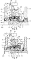
- Fig. 3
- eine Längsschnittdarstellung einer nach einem bevorzugten Ausführungsbeispiel umgesetzten, in dem jeweiligen Antriebssystem der
Fign. 1 und2 eingesetzten Schalteinrichtung, wobei sich eine die Schaltstellung der Schalteinrichtung vorgebende Schiebehülse in einer ersten Verschiebestellung befindet, in der eine zentrale Motorwelle mit einem mit einem ersten Elektromotor gekoppelten ersten Zahnrad rotatorisch verbunden ist, - Fig. 4
- ein Diagramm zur Veranschaulichung unterschiedlicher, durch die Antriebssysteme der
Fign. 1 und2 umsetzbarer Betriebszustände, - Fig. 5
- eine Längsschnittdarstellung der Schalteinrichtung, ähnlich zur
Fig. 3 , wobei sich die Schiebehülse in einer im Vergleich zuFig. 3 geänderten zweiten Verschiebestellung befindet, in welcher zweiten Verschiebestellung sowohl die Motorwelle als auch ein mit einem zweiten Elektromotor gekoppeltes zweites Zahnrad mit dem ersten Zahnrad rotatorisch verbunden sind, sowie - Fig. 6
- eine Längsschnittdarstellung der Schalteinrichtung, ähnlich zu
Fig. 3 , wobei die Schiebehülse eine dritte Verschiebestellung einnimmt, in der die Motorwelle im Vergleich zuFig. 5 von dem ersten Zahnrad sowie dem zweiten Zahnrad rotatorisch entkoppelt ist. - Die Figuren sind lediglich schematischer Natur und dienen ausschließlich dem Verständnis der Erfindung. Die gleichen Elemente sind mit denselben Bezugszeichen versehen. Auch sind die unterschiedlichen Merkmale der verschiedenen Ausführungsbeispiele prinzipiell frei miteinander kombinierbar.
- In Verbindung mit
Fig. 1 ist zunächst ein Antriebssystem 1 nach einem bevorzugten ersten Ausführungsbeispiel veranschaulicht. Das Antriebssystem 1 ist in einem hybriden Kraftfahrzeug integriert, welches Kraftfahrzeug mit dem Bezugszeichen 31 angedeutet ist. Insbesondere ist in dieser Ausführung eine Antriebsachse 32 des Kraftfahrzeuges 31 (hier Vorderachse, alternativ auch Hinterachse) mit dargestellt, wobei Räder 9a, 9b der Antriebsachse 32 über verschiedene Maschinen (Verbrennungskraftmaschine 3 sowie Elektromotoren 6, 8) des Antriebssystems 1 antreibbar ist. Eine Verbrennungskraftmaschine 3 des Antriebssystems 1 befindet sich in dieser Ausführung in einer bevorzugten Front-Quer-Anordnung, in der eine Längsachse der Verbrennungskraftmaschine 3, d. h. eine (erste) Drehachse 43a einer Ausgangswelle 2 (Kurbelwelle) der Verbrennungskraftmaschine 3 quer, hier senkrecht, zu einer Längsachse (Fahrzeuglängsachse) des Kraftfahrzeuges 31 ausgerichtet ist. - Gemäß der Ausbildung des Antriebssystems 1 als serieller Hybridantrieb, weist das Antriebssystem 1 neben der Verbrennungskraftmaschine 3 auch zwei Elektromotoren 6, 8 auf. Ein erster Elektromotor 6 ist in der
Fig. 1 mit Generator bezeichnet und demnach in einem Hauptbetriebszustand als Generator wirkend eingesetzt. Der erste Elektromotor 6 ist jedoch prinzipiell, etwa für ein rein elektrisches Rückwärtsfahren als Antriebsmotor schaltbar. Ein zweiter Elektromotor 8, der eine durch den ersten Elektromotor 6 generierte elektrische Leistung verbraucht, ist als Antriebsmotor / Fahrmotor umgesetzt. - Die beiden Elektromotoren 6, 8 sind mit Drehachsen 43b, 43c ihrer Rotorwellen 5, 7 in radialer Richtung versetzt zueinander angeordnet. Der erste Elektromotor 6 weist eine erste Rotorwelle 5 auf, die um eine (zweite) Drehachse 43b drehbar gelagert ist. Der zweite Elektromotor 8 weist eine zweite Rotorwelle 7 auf, die um eine (dritte) Drehachse 43c drehbar gelagert ist. Der erste Elektromotor 6 ist gesamtheitlich, d.h. auch samt seines hier der Übersichtlichkeit halber nicht dargestellten Stators und seines relativ zu dem Stator drehbar angeordneten Rotor, der mit der ersten Rotorwelle 5 drehfest verbunden ist, in radialer Richtung der zweiten Drehachse 43b versetzt zu dem gesamten zweiten Elektromotor 8 samt seines Stators und seines relativ zu dem Stator drehbar angeordneten, mit der zweiten Rotorwelle 7 drehfest verbundenen Rotors angeordnet. Auch sind die beiden Elektromotoren 6, 8 relativ zu der ersten Drehachse 43a der Ausgangswelle 2 der Verbrennungskraftmaschine 3 radial versetzt angeordnet. Entlang der Fahrzeuglängsachse gesehen, befindet sich die erste Drehachse 43a zwischen der zweiten Drehachse 43b und der dritten Drehachse 43c.
- Zum Umsetzen der unterschiedlichen in
Fig. 4 angedeuteten Betriebszustände des Antriebssystems 1 ist zwischen der Verbrennungskraftmaschine 3 / der Ausgangswelle 2, den beiden Elektromotoren 6, 8 mit ihren beiden Rotorwellen 5, 7 und einem Antriebsteil 10 des Antriebssystems 1 eine Getriebeeinheit 11 vorgesehen. Die Getriebeeinheit 11 ist als Schaltgetriebe realisiert und zur Umsetzung der verschiedenen Betriebszustände in verschiedene Schaltstellungen verbringbar. Die Getriebeeinheit 11 ist durch eine erfindungsgemäße Schalteinrichtung 12, die nachfolgend in Bezug auf dieFign. 3 ,5 und 6 näher beschrieben ist, ansteuerbar. - Die Getriebeeinheit 11 weist eine zentral angeordnete Motorwelle 4 (auch vereinfacht als Welle bezeichnet) auf, die mit der Ausgangswelle 2 drehfest gekoppelt ist bzw. unmittelbar durch einen Bereich der Ausgangswelle 2 umgesetzt ist. Die Motorwelle 4 ist koaxial zu der Ausgangswelle 2 angeordnet und somit um die gemeinsame erste Drehachse 43a drehbar. Die Getriebeeinheit 11 weist zudem ein erstes Zahnrad 13 auf, welches erste Zahnrad 13 permanent mit der ersten Rotorwelle 5 drehfest verbunden / gekoppelt ist. Das erste Zahnrad 13 ist koaxial zu der Motorwelle 4 angeordnet. Das erste Zahnrad 13 ist als Hohlwellenzahnrad / Hohlwelle ausgebildet und radial von außen auf der Motorwelle 4 drehbar gelagert. Zur drehfesten Verbindung des ersten Zahnrades 13 mit der ersten Rotorwelle 5 ist ein weiteres (drittes) Zahnrad 42 vorgesehen, welches dritte Zahnrad 42 drehfest auf der ersten Rotorwelle 5 angeordnet ist und sich in Zahneingriff mit dem ersten Zahnrad 13 befindet. Das dritte Zahnrad 42 wird ebenfalls als Bestandteil der Getriebeeinheit 11 angesehen.
- Des Weiteren weist die Getriebeeinheit 11 ein zweites Zahnrad 15 auf, welches zweite Zahnrad 15 zur Koppelung mit der zweiten Rotorwelle 7 dient. Das zweite Zahnrad 15 ist in axialer Richtung der Motorwelle 4, d. h. entlang der ersten Drehachse 43a betrachtet, neben dem ersten Zahnrad 13 angeordnet. Auch das zweite Zahnrad 15 ist als Hohlwellenzahnrad / Hohlwelle realisiert und radial von außen auf der Motorwelle 4 drehbar gelagert. Das zweite Zahnrad 15 ist in dieser Ausführung über ein Zwischenzahnrad 20 mit einer Planetengetriebestufe 14 verbunden. Die Planetengetriebestufe 14 ist weiter mit der zweiten Rotorwelle 7 rotatorisch verbunden. Wie aus
Fig. 1 weiterhin zu erkennen ist, ist das mit dem zweiten Zahnrad 15 kämmende Zwischenzahnrad 20 unmittelbar drehfest mit einem Planetenträger 19 der ein Planetenteilgetriebe 16 bildenden Planetengetriebestufe 14 verbunden. Das Planetenteilgetriebe 16 der Getriebeeinheit 11 weist zudem auf typische Weise ein Sonnenrad 17 auf, das unmittelbar drehfest mit der zweiten Rotorwelle 7 verbunden ist. Mit dem Sonnenrad 17 befinden sich wiederum mehrere in Umfangsrichtung verteilt angeordnete Planetenräder 18, die auf dem Planetenträger 19 drehbar aufgenommen sind, in Zahneingriff. Ein mit den Planetenrädern 18 weiterhin in Zahneingriff stehendes Hohlrad 21 wirkt mit einer Bremseinrichtung 22 zusammen. Die gehäusefeste, d. h. fahrzeugrahmenfeste, Bremseinrichtung 22 hält in ihrem aktivierten Zustand das Hohlrad 21 relativ zu einem Fahrzeugrahmen fest. In ihrem deaktivierten Zustand ist eine freie Verdrehung des Hohlrades 21 gegenüber dem Fahrzeugrahmen ermöglicht, sodass die Bremseinrichtung 22 das Hohlrad 21 rotatorisch freigibt. - Das zweite Zahnrad 15 befindet sich in dem ersten Ausführungsbeispiel zudem in drehfester Verbindung mit dem Antriebsteil 10. Das Antriebsteil 10 weist eine Verzahnung 24 auf, mit der sich das zweite Zahnrad 15 in Zahneingriff befindet. Das Antriebsteil 10 ist hier als ein Eingangsrad eines Differentialgetriebes 23 der Antriebsachse 32 ausgestaltet. Das Antriebsteil 10 ist folglich permanent mit den beiden dargestellten Rädern 9a, 9b des Kraftfahrzeuges 31 rotatorisch verbunden.
- Erfindungsgemäß ist zwischen der Motorwelle 4 und den beiden Rotorwellen 5, 7, nämlich den beiden mit den Rotorwellen 5, 7 gekoppelten Zahnrädern 13 und 15, die Schalteinrichtung 12 wirkend eingesetzt. Die in
Fig. 3 näher dargestellte Schalteinrichtung 12 ist prinzipiell derart ausgebildet, dass sie in ihrer ersten Schaltstellung die Motorwelle 4 mit der ersten Rotorwelle 5 rotatorisch koppelt / verbindet, während die zweite Rotorwelle 7 von der Motorwelle 4 (sowie der ersten Rotorwelle 5) rotatorisch entkoppelt ist (Fig. 3 ). In einer zweiten Schaltstellung der Schalteinrichtung 12 ist die Motorwelle 4 sowohl mit der ersten Rotorwelle 5 als auch mit der zweiten Rotorwelle 7 rotatorisch verbunden / gekoppelt (Fig. 5 ). In einer dritten Schaltstellung der Schalteinrichtung 12 sind die beiden Rotorwellen 5, 7 miteinander rotatorisch verbunden / gekoppelt, während die Motorwelle 4 von den beiden Rotorwellen 5, 7 rotatorisch entkoppelt ist (Fig. 6 ). - Die Schalteinrichtung 12 ist zumindest teilweise unmittelbar in dem ersten Zahnrad 13 integriert. Die Schalteinrichtung 12 weist eine Schiebehülse 26 auf, die entlang der zentralen ersten Drehachse 43a axial verschiebbar in dem ersten Zahnrad 13 aufgenommen ist. Durch Verschieben dieser Schiebehülse 26 in unterschiedliche Verschiebestellungen lassen sich die in den
Fign. 3 ,5 und 6 veranschaulichten unterschiedlichen Schaltstellungen der Schalteinrichtung 12 verwirklichen. Die Schiebehülse 26 weist einen Grundkörper 44 auf, der unmittelbar in einem Aufnahmeloch 45 in Form eines Durchgangsloches innerhalb des ersten Zahnrades 13 verschiebbar aufgenommen ist. Die Schiebehülse 26 ist zudem unmittelbar drehfest mit dem ersten Zahnrad 13 gekoppelt. Die Schiebehülse 26 weist eine Innenverzahnung 46 auf, die mit verschiedenen Übertragungsbereichen 28, 30 an der Motorwelle 4 und dem zweiten Zahnrad 15 zusammenwirkt. Neben dem Grundkörper 44 ist der Schiebehülse 26 ein Schiebeteil 47 zugeordnet, welches Schiebeteil 47 mit einem ersten Ende 39a eines Hebelelementes 38 verbunden ist. Das Schiebeteil 47 weist zu seiner radialen Außenseite hin eine Aufnahmekontur 40 auf, in der das erste Ende 39a formschlüssig eingreift. Das Schiebeteil 47 ist an dem Grundkörper 44 befestigt. Die als Axialverzahnung / Kerbverzahnung umgesetzte Innenverzahnung 46 ist in dem Schiebeteil 47 und dem Grundkörper 44 durchgängig eingebracht. - Das Hebelelement 38 ist Bestandteil eines Hebelmechanismus 37, der zum Koppeln eines als Linearmotor umgesetzten Aktuators 36 mit der Schiebehülse 26 dient. Das Hebelelement 38 ist in Bezug auf einen Schwenkpunkt 41 an einem Gehäuse 48 drehbar / schwenkbar abgestützt. Ein dem ersten Ende 39a entgegengesetztes zweites Ende 39b des Hebelelementes 38 befindet sich unmittelbar mit dem Aktuator 36 in Wirkzusammenhang. Somit ist die Schiebehülse 26 durch den Aktuator 36 in ihrer Verschiebestellung einstellbar.
- Die Schiebehülse 26 weist einen ersten Verbindungsbereich 27 auf, der hier einen ersten Verzahnungsbereich der Innenverzahnung 46 darstellt. Der erste Verbindungsbereich 27 ist mit einem ersten Übertragungsbereich 28 (ebenfalls als Verzahnungsbereich realisiert) seitens der Motorwelle 4 formschlüssig in Drehrichtung koppelbar. In der in
Fig. 3 dargestellten ersten Schaltstellung (entsprechend erster Verschiebestellung der Schiebehülse 26) ist die Motorwelle 4 durch Zahneingriff des ersten Übertragungsbereichs 28 in dem ersten Verbindungsbereich 27 drehfest mit dem ersten Zahnrad 13 verbunden. InFig. 5 ist die zweite Schaltstellung der Schalteinrichtung 12 (entsprechend einer zweiten Verschiebestellung der Schiebehülse 26) dargestellt, in der sowohl der erste Verbindungsbereich 27 drehfest mit dem ersten Übertragungsbereich 28 verbunden ist als auch ein zweiter Verbindungsbereich 29 (ebenfalls als Verzahnungsbereich realisiert) der Schiebehülse 26 drehfest mit einem zweiten Übertragungsbereich 30 (ebenfalls als Verzahnungsbereich realisiert) des zweiten Zahnrades 15 befindet. Während der erste Verbindungsbereich 27 vorzugsweise durch das Schiebeteil 47 realisiert ist, ist der zweite Verbindungsbereich 29 vorzugsweise unmittelbar durch den Grundkörper 44 realisiert. Gemäß der inFig. 6 gezeigten dritten Schaltstellung der Schalteinrichtung 12 (entsprechend einer dritten Verschiebestellung der Schiebehülse 26) sind die beiden Zahnräder 13 und 15 schließlich drehfest miteinander verbunden, wobei die Motorwelle 4 von dem ersten Zahnrad 13 und somit auch von dem zweiten Zahnrad 15 rotatorisch entkoppelt ist. Die Schiebehülse 26 befindet sich somit mit ihrem ersten Verbindungsbereich 27 außer Zahneingriff mit dem ersten Übertragungsbereich 28. - In Verbindung mit den
Fign. 3 ,5 und 6 ist zudem zu erkennen, dass zur Abstützung der Schiebehülse 26 in der jeweiligen Verschiebestellung eine Rastiereinheit 25 vorgesehen ist. Die Rastiereinheit 25 ist ebenfalls in dem ersten Zahnrad 13 integriert. Die Rastiereinheit 25 weist ein Rastelement 34 auf, das in dem ersten Zahnrad 13 radial verschiebbar angeordnet ist und mit einer Rastkontur 33 in der Schiebehülse 26 zusammenwirkt. Das Rastelement 34 stützt die Schiebehülse 26 in ihrer jeweiligen Verschiebestellung verschiebefest relativ zu dem ersten Zahnrad 13 ab. - Wie zudem in den
Fign. 3 ,5 und 6 erkennbar, ist in den Ausführungen die Motorwelle 4 auf typische Weise relativ zu dem Gehäuse 48 drehbar gelagert. Zwischen zwei Stützlagern 49, an denen die Motorwelle 4 relativ zu dem Gehäuse 48 abgestützt ist, sind die beiden ersten und zweiten Zahnräder 13, 15 relativ verdrehbar auf der Außenseite der Motorwelle 4 gelagert. Das zweite Zahnrad 15 / der zweite Übertragungsbereich 30 befindet sich auf einer zweiten axialen Seite 35b des ersten Zahnrades 13, die dem zu einer ersten axialen Seite 35a hin angeordneten ersten Übertragungsbereich 28 abgewandt ist. - Somit sind erfindungsgemäß die in
Fig. 4 veranschaulichten Betriebszustände durch das Antriebssystem 1 realisierbar. InFig. 4 ist mit Verbrenner allgemein die mit der Verbrennungskraftmaschine 3 gekoppelte Motorwelle 4 bezeichnet, als Generator das erste Zahnrad 13 und als Abtrieb das zweite Zahnrad 15. In einem typischen seriellen Fahrbetrieb (in der ersten Schaltstellung der Schalteinrichtung 12) treibt die Verbrennungskraftmaschine 3 den ersten Elektromotor 6 an, der wiederum elektrisch den zweiten Elektromotor 8 mit Antriebsenergie versorgt. Der zweite Elektromotor 8 bringt ein Drehmoment auf die Räder 9a, 9b auf. Der erste Elektromotor 6 dient dabei zur Erzeugung einer entsprechenden elektrischen Energie, die in einer Batterie zwischengespeichert wird. Ein elektrischer Fahrzustand bei entkoppelter Verbrennungskraftmaschine 3 (gemäß der dritten Schaltstellung der Schalteinrichtung 12) erfolgt durch Betrieb des zweiten Elektromotors 8 (mit einer elektrischen Energie aus der Batterie). Ein verbrennungsmotorisches Fahren erfolgt typischerweise in der zweiten Schaltstellung der Schalteinrichtung 12, indem sowohl die Verbrennungskraftmaschine 3, der erste Elektromotor 6 als auch der zweite Elektromotor 8 mit dem ersten Zahnrad 13 gekoppelt sind. Ein Standladen erfolgt typischerweise ebenfalls in der ersten Schaltstellung. - In Verbindung mit
Fig. 2 ist schließlich ein weiteres bevorzugtes zweites Ausführungsbeispiele realisiert, das im Wesentlichen gemäß dem ersten Ausführungsbeispiel umgesetzt ist. Der Kürze wegen wird daher lediglich auf die Unterschiede zu diesen beiden Ausführungsbeispielen eingegangen. Wie inFig. 2 ersichtlich, befindet sich das zweite Zahnrad 15 nicht mehr in direktem Zahneingriff mit dem Antriebsteil 10, sondern unter Zwischenschaltung des Zwischenzahnrads 20 in indirekter Drehverbindung mit dem Antriebsteil 10. Umgekehrt befindet sich das Zwischenzahnrad 20 somit in direktem Zahneingriff mit dem Antriebsteil 10 sowie dem zweiten Zahnrad 15. Auch sind die beiden Elektromotoren 6, 8 nun gegensinnig im Vergleich zuFig. 2 in Bezug auf die erste Drehachse 43a angeordnet, wobei der zweite Elektromotor 8 samt dem Planetenteilgetriebe 16 näher zur Antriebsachse 32 hin angeordnet ist als der erste Elektromotor 6. - In anderen Worten ausgedrückt, wird durch das erfindungsgemäße Antriebssystem 1 eine Struktur für Hybridfahrzeuge bereitgestellt, die einen direkten Verbrenner-Durchtrieb zum Rad 9a, 9b vorsieht. Bei solchen Fahrzeug- bzw. Getriebekonzepten sind folgende Fahrmodi darzustellen: A) Serielles Fahren: Verbrenner 3 und Generator 6 erzeugen elektrische Energie, um den Fahrmotor 8 zu betreiben; B) Elektrisches Fahren aus Batterie, wobei der Verbrenner 3 abgekoppelt ist; C) Verbrenner-Betrieb: Verbrenner 3 ist direkt mit den Rädern 9a, 9b verbunden; D) Standladen: wie A), nur bei stehendem Fahrzeug 31. Die einzelnen Fahrmodi und Schaltzustände des Schaltelementes 12 sind in der Tabelle nach
Fig. 4 grafisch dargestellt. Zu erkennen ist dabei, dass der Generator 6 in jedem der Fahrmodi aktiv ist und somit ein zentrales Element des Aufbaus / Antriebssystems 1 darstellt. Daraus ergibt sich, dass eine technische Ausführung zum Verbinden der Ein- und Ausgänge durch z.B. zwei Verbindungselemente 27, 29 möglich ist. Dabei ist das erste Verbindungselement 27 zwischen der Motorwelle 4 und dem ersten Zahnrad 13, und das zweite Verbindungselement 29 zwischen dem ersten Zahnrad 13 und dem zweiten Zahnrad wirkend angeordnet. Denkbar sind auch alle Arten von form- oder reibschlüssigen, hydrostatischen, magnetischen oder anderen Verbindungen. Besonders vorteilhaft ist eine mit denFign. 3 ,5 und 6 dargestellte Lösung, die zur Betätigung nur ein Aktuator-System 36 benötigt. - Das Schaltelement 12 ist auf Basis einer Doppelschaltsynchronisierung ausgeführt. Im Gegensatz zu einer herkömmlichen Ausführung besitzt diese keine Neutralstellung sondern verbindet in der Mittelposition alle drei Elemente 4, 13 ,15. In
Fig. 3 befindet sich die Schiebemuffe 26 links. Somit ist ein serieller Betrieb umgesetzt, eine Verbindung von Verbrenner 3 mit Generator 6 liegt vor. InFig. 5 ist die Schiebemuffe 26 mittig. Somit ist ein Verbrenner-Betrieb ermöglicht, in dem der Verbrenner 3 mit den Rädern 9a, 9b sowie dem Generator 6 verbunden ist. InFig. 6 befindet sich die Schiebemuffe rechts. Dabei ist ein elektrisches Fahren aus einer Batterie möglich, wobei der Generator 6 mit dem Abtrieb verbunden ist. Das Schaltelement 12 besteht aus zwei Synchronisationseinheiten mit den dazugehörigen Synchroverzahnungen sowie einer Schiebemuffe 12 mit Eingriff für das Betätigungselement und einer Arretierung 25 für die einzelnen Schaltpositionen. Die Arretierungselemente 34 sind in dem ersten Zahnrad 13 integriert. Das Zahnrad 13 ist mit Durchgriffen versehen, wodurch die Schiebemuffe 26 beide seitlichen Elemente verbindet und trotzdem mit nur einem Betätigungssystem aktuiert werden kann. -
- 1
- Antriebssystem
- 2
- Ausgangswelle
- 3
- Verbrennungskraftmaschine
- 4
- Motorwelle
- 5
- erste Rotorwelle
- 6
- erster Elektromotor
- 7
- zweite Rotorwelle
- 8
- zweiter Elektromotor
- 9a
- erstes Rad
- 9b
- zweites Rad
- 10
- Antriebsteil
- 11
- Getriebeeinheit
- 12
- Schalteinrichtung
- 13
- erstes Zahnrad
- 14
- Planetengetriebestufe
- 15
- zweites Zahnrad
- 16
- Planetenteilgetriebe
- 17
- Sonnenrad
- 18
- Planetenrad
- 19
- Planetenträger
- 20
- Zwischenzahnrad
- 21
- Hohlrad
- 22
- Bremseinrichtung
- 23
- Differentialgetriebe
- 24
- Verzahnung
- 25
- Rastiereinheit
- 26
- Schiebehülse
- 27
- erster Verbindungsbereich
- 28
- erster Übertragungsbereich
- 29
- zweiter Verbindungsbereich
- 30
- zweiter Übertragungsbereich
- 31
- Kraftfahrzeug
- 32
- Antriebsachse
- 33
- Rastkontur
- 34
- Rastelement
- 35a
- erste Seite
- 35b
- zweite Seite
- 36
- Aktuator
- 37
- Hebelmechanismus
- 38
- Hebelelement
- 39a
- erstes Ende
- 39b
- zweites Ende
- 40
- Aufnahmekontur
- 41
- Schwenkpunkt
- 42
- drittes Zahnrad
- 43a
- erste Drehachse
- 43b
- zweite Drehachse
- 43c
- dritte Drehachse
- 44
- Grundkörper
- 45
- Aufnahmeloch
- 46
- Innenverzahnung
- 47
- Schiebeteil
- 48
- Gehäuse
- 49
- Stützlager
Claims (10)
- Schalteinrichtung (12) für ein hybrides Antriebssystem (1) eines Kraftfahrzeuges (31), mit einer zentral angeordneten Welle (4), einem relativ zu der Welle (4) verdrehbar gelagerten ersten Zahnrad (13) und einem relativ zu der Welle (4) verdrehbar gelagerten, entlang der Welle (4) versetzt zu dem ersten Zahnrad (13) angeordneten zweiten Zahnrad (15), einer unmittelbar in dem ersten Zahnrad (13) verschiebbar aufgenommenen sowie drehfest mit dem ersten Zahnrad (13) verbundenen Schiebehülse (26), dadurch gekennzeichnet, dass die Schiebehülse (26) derart ausgebildet ist, dass sie in einer ersten Verschiebestellung die Welle (4) drehfest mit dem ersten Zahnrad (13) verbindet, während das zweite Zahnrad (15) rotatorisch von der Welle (4) entkoppelt ist, in einer zweiten Verschiebestellung die Welle (4) sowohl mit dem ersten Zahnrad (13) als auch mit dem zweiten Zahnrad (15) rotatorisch verbindet und in einer dritten Verschiebestellung die beiden Zahnräder (13, 15) miteinander rotatorisch verbindet, während die Welle (4) von den beiden Zahnrädern (13, 15) rotatorisch entkoppelt ist.
- Schalteinrichtung (12) nach Anspruch 1, dadurch gekennzeichnet, dass die Schiebehülse (26) eine Rastkontur (33) aufweist, in welche Rastkontur (33) ein Rastelement (34) in der jeweiligen Verschiebestellung blockierend eingreift.
- Schalteinrichtung (12) nach Anspruch 2, dadurch gekennzeichnet, dass das Rastelement (34) in dem ersten Zahnrad (13) aufgenommen ist.
- Schalteinrichtung (12) nach einem der Ansprüche 1 bis 3, dadurch gekennzeichnet, dass die Schiebehülse (26) einen mit der Welle (4) zusammenwirkenden ersten Verbindungsbereich (27) und einen mit dem zweiten Zahnrad (15) zusammenwirkenden, axial versetzt zu dem ersten Verbindungsbereich (27) angeordneten, zweiten Verbindungsbereich (29) aufweist.
- Schalteinrichtung (12) nach Anspruch 4, dadurch gekennzeichnet, dass ein mit dem ersten Verbindungsbereich (27) koppelbarer Übertragungsbereich (28) der Welle (4) zu einer ersten axialen Seite (35a) des ersten Zahnrades (13) hin angeordnet ist und ein mit dem zweiten Verbindungsbereich (29) koppelbarer Übertragungsbereich (30) des zweiten Zahnrades (15) zu einer der ersten axialen Seite (35a) abgewandten zweiten axialen Seite (35b) des ersten Zahnrades (13) hin angeordnet ist.
- Schalteinrichtung (12) nach einem der Ansprüche 1 bis 5, dadurch gekennzeichnet, dass ein Aktuator (36) über einen Hebelmechanismus (37) auf die Schiebehülse (26) verschiebend einwirkt.
- Schalteinrichtung (12) nach Anspruch 6, dadurch gekennzeichnet, dass ein Hebelelement (38) des Hebelmechanismus (37) mit einem ersten Ende (39a) in eine Aufnahmekontur (40) an der Schiebehülse (26) eingreift und mit einem dem ersten Ende (39a) gegenüberliegenden zweiten Ende (39b) durch den Aktuator (36) zum Schwenken um einen gehäusefesten Schwenkpunkt (41) beaufschlagbar ist.
- Antriebssystem (1) für ein hybrides Kraftfahrzeug (31) (vorzugsweise serieller Hybridantrieb), mit einer mit einer Ausgangwelle (2) einer Verbrennungskraftmaschine (3) rotatorisch koppelbaren oder gekoppelten Motorwelle (4), einem eine erste Rotorwelle (5) aufweisenden, in einem Hauptbetriebszustand als Generator betriebenen ersten Elektromotor (6), einem eine radial versetzt zu der ersten Rotorwelle (5) angeordnete zweite Rotorwelle (7) aufweisenden, in dem Hauptbetriebszustand als Antriebsmotor betriebenen zweiten Elektromotor (8), einem mit der zweiten Rotorwelle (7) rotatorisch verbundenen und zumindest einem Rad (9a, 9b) des Kraftfahrzeuges (31) rotatorisch verbindbaren Antriebsteil (10) sowie einer zwischen der Motorwelle (4), den beiden Rotorwellen (5, 7) und dem Antriebsteil (10) wirkend eingesetzten, schaltbaren Getriebeeinheit (11), wobei eine eine Schaltstellung der Getriebeeinheit (11) steuernde und nach einem der Ansprüche 1 bis 7 ausgebildete Schalteinrichtung (12) zwischen der Motorwelle (4), einem mit der ersten Rotorwelle (5) permanent rotatorisch gekoppelten ersten Zahnrad (13) und einem mit der zweiten Rotorwelle (7) über eine zusätzliche Planetengetriebestufe (14) permanent rotatorisch gekoppelten zweiten Zahnrad (15) derart wirkend eingesetzt ist, dass die Schalteinrichtung (12) in einer ersten Schaltstellung die Motorwelle (4) mit der ersten Rotorwelle (5) rotatorisch verbindet, während die zweite Rotorwelle (7) von der Motorwelle (4) rotatorisch entkoppelt ist, in einer zweiten Schaltstellung die Motorwelle (4) sowohl mit der ersten Rotorwelle (5) als auch mit der zweiten Rotorwelle (7) rotatorisch verbindet und in einer dritten Schaltstellung die beiden Rotorwellen (5, 7) miteinander rotatorisch verbindet, während die Motorwelle (4) von den beiden Rotorwellen (5, 7) rotatorisch entkoppelt ist.
- Antriebssystem (1) nach Anspruch 8, dadurch gekennzeichnet, dass die Planetengetriebestufe (14) durch ein Planetenteilgetriebe (16) ausgebildet ist, von welchem Planetenteilgetriebe (16) ein Sonnenrad (17) unmittelbar mit der zweiten Rotorwelle (7) permanent verbunden ist, ein mehrere Planetenräder (18) lagernder Planetenträger (19) mit einem Zwischenzahnrad (20), das sich in Zahneingriff mit dem zweiten Zahnrad (15) befindet, verbunden ist und ein Hohlrad (21) mittels einer Bremseinrichtung (22) fahrzeugrahmenfest anordenbar ist.
- Kraftfahrzeug (31) mit einem Antriebssystem (1) nach Anspruch 8 oder 9, wobei das Antriebsteil (10) mit den Rädern (9a, 9b) des Kraftfahrzeuges (31) rotatorisch gekoppelt ist.
Applications Claiming Priority (2)
| Application Number | Priority Date | Filing Date | Title |
|---|---|---|---|
| DE102019110044.5A DE102019110044A1 (de) | 2019-04-16 | 2019-04-16 | Schalteinrichtung für ein hybrides Antriebssystem eines Kraftfahrzeuges; Antriebssystem sowie Kraftfahrzeug |
| PCT/DE2020/100208 WO2020211894A1 (de) | 2019-04-16 | 2020-03-17 | Schalteinrichtung für ein hybrides antriebssystem eines kraftfahrzeuges; antriebssystem sowie kraftfahrzeug |
Publications (2)
| Publication Number | Publication Date |
|---|---|
| EP3956165A1 EP3956165A1 (de) | 2022-02-23 |
| EP3956165B1 true EP3956165B1 (de) | 2022-11-30 |
Family
ID=70154213
Family Applications (1)
| Application Number | Title | Priority Date | Filing Date |
|---|---|---|---|
| EP20716387.4A Active EP3956165B1 (de) | 2019-04-16 | 2020-03-17 | Schalteinrichtung für ein hybrides antriebssystem eines kraftfahrzeuges; antriebssystem sowie kraftfahrzeug |
Country Status (6)
| Country | Link |
|---|---|
| US (1) | US11945311B2 (de) |
| EP (1) | EP3956165B1 (de) |
| KR (1) | KR102913632B1 (de) |
| CN (1) | CN113597383B (de) |
| DE (1) | DE102019110044A1 (de) |
| WO (1) | WO2020211894A1 (de) |
Families Citing this family (5)
| Publication number | Priority date | Publication date | Assignee | Title |
|---|---|---|---|---|
| DE102019131956A1 (de) * | 2019-04-16 | 2020-10-22 | Schaeffler Technologies AG & Co. KG | Antriebssystem für ein hybrides Kraftfahrzeug mit umsetzbarem Direktdurchtrieb zu einem Rad; sowie Kraftfahrzeug |
| DE102019131935B4 (de) * | 2019-11-26 | 2025-12-31 | Knorr-Bremse Systeme für Nutzfahrzeuge GmbH | Integration eines Getriebestellers |
| DE102021102189A1 (de) | 2021-02-01 | 2022-08-04 | Bayerische Motoren Werke Aktiengesellschaft | Drehmomentübertragungseinrichtung für eine Motor-Getriebe-Anordnung, Motor-Getriebe-Anordnung sowie Kraftfahrzeug |
| CN214728144U (zh) * | 2021-03-15 | 2021-11-16 | 赛格威科技有限公司 | 混合动力全地形车 |
| DE102024124414A1 (de) | 2024-08-27 | 2026-03-05 | Bayerische Motoren Werke Aktiengesellschaft | Antriebsachse und Antriebseinrichtung für ein Kraftfahrzeug sowie Kraftfahrzeug |
Family Cites Families (29)
| Publication number | Priority date | Publication date | Assignee | Title |
|---|---|---|---|---|
| GB1166520A (en) * | 1966-12-17 | 1969-10-08 | Mitsubishi Heavy Ind Ltd | Coupling Construction |
| US5862900A (en) * | 1995-11-06 | 1999-01-26 | Chrysler Corporation | Transmission synchronizer mechanism |
| KR100293543B1 (ko) | 1997-10-15 | 2001-10-24 | 이계안 | 하이브리드변속기 |
| US6793600B2 (en) * | 2001-11-28 | 2004-09-21 | Kazuyoshi Hiraiwa | Powertrain for hybrid electric vehicles |
| CA2523771C (en) * | 2003-05-30 | 2011-04-12 | Tm4 Inc. | Hybrid drive train for vehicle |
| CA2430157A1 (fr) | 2003-05-30 | 2004-11-30 | Tm4 Inc. | Systeme de traction pour vehicule electrique |
| US7678003B2 (en) | 2007-01-19 | 2010-03-16 | Ford Global Technologies, Llc | Hybrid vehicle transmission with a mechanical reverse function |
| DE102007040040A1 (de) * | 2007-08-24 | 2009-02-26 | Zf Friedrichshafen Ag | Schaltelement umfassend zumindest drei Schaltstellungen zum Schalten von zwei Übersetzungsstufen |
| EP2322822B1 (de) * | 2009-11-13 | 2012-03-07 | C.R.F. Società Consortile per Azioni | Doppelkupplungsgetriebe eines Kraftfahrzeugs mit Gangschaltungsvorrichtung, die eine Drehtrommel umfasst, und Hybridantriebssystem eines Kraftfahrzeugs, das ein solches Getriebe beinhaltet |
| DE102011007266B4 (de) * | 2011-04-13 | 2019-02-28 | Schaeffler Technologies AG & Co. KG | Schalteinrichtung mit einer Kupplungseinrichtung |
| DE102011085201A1 (de) | 2011-10-26 | 2013-05-02 | Zf Friedrichshafen Ag | Vorrichtung für einen Antriebsstrang eines Hybridfahrzeugs, Antriebsstrang und Verfahren zum Betreiben derselben |
| DE102012210287A1 (de) * | 2012-06-19 | 2013-12-19 | Zf Friedrichshafen Ag | Verbindungsvorrichtung und Getriebe für einen Fahrzeugantriebsstrang sowie Verfahren zur Betätigung einer solchen Verbindungsvorrichtung |
| DE102012015006A1 (de) * | 2012-07-28 | 2014-01-30 | GM Global Technology Operations LLC (n. d. Gesetzen des Staates Delaware) | Kuppelvorrichtung mit einer Schaltmuffe fürein Schaltgetriebe |
| DE102012024751A1 (de) | 2012-12-17 | 2014-06-18 | Volkswagen Aktiengesellschaft | Übersetzungs- und Ausgleichsgetriebe sowie Motor- und Getriebeeinheit |
| DE102013221130A1 (de) * | 2013-10-17 | 2015-04-23 | Zf Friedrichshafen Ag | Vorrichtung zum lösbaren Verbinden von zwei Bauteilen mit wenigstens einer Welle |
| CN103660910B (zh) * | 2013-12-06 | 2016-01-06 | 合肥工业大学 | 一种油电静液复合的混合动力传动系统 |
| CN104228562A (zh) * | 2014-08-19 | 2014-12-24 | 枣庄益新机械制造有限公司 | 一种新能源混合动力汽车多功能无极变速箱 |
| US9523396B2 (en) * | 2014-12-08 | 2016-12-20 | Gm Global Technology Operations, Llc | Hydraulic dog clutch |
| KR101703576B1 (ko) * | 2014-12-15 | 2017-02-07 | 현대자동차 주식회사 | 차량의 변속장치 |
| DE112015006341A5 (de) * | 2015-03-20 | 2018-01-18 | Dr. Ing. H.C. F. Porsche Aktiengesellschaft | Elektrischer achsantrieb für ein kraftfahrzeug |
| KR101786397B1 (ko) | 2016-10-27 | 2017-10-17 | 현대자동차주식회사 | 하이브리드 차량의 파워트레인 |
| DE102017100724A1 (de) * | 2017-01-16 | 2018-07-19 | Ludger Sorig | Elektrisches Einpresskontaktelement |
| DE102017200724B4 (de) | 2017-01-18 | 2020-02-20 | Magna powertrain gmbh & co kg | Getriebeanordnung zur steuerbaren Verteilung eines Antriebsmoments von einem Eingangselement auf zumindest ein Ausgangselement in einem Allradantriebsstrang eines Allradkraftfahrzeugs |
| DE102017206510A1 (de) | 2017-04-18 | 2018-10-18 | Volkswagen Aktiengesellschaft | Getriebestruktur für ein seriell/paralleles Hybridfahrzeug |
| CN107697061B (zh) * | 2017-09-25 | 2020-09-04 | 奇瑞汽车股份有限公司 | 混合动力驱动系统及混合动力汽车 |
| DE102017127577A1 (de) * | 2017-11-22 | 2019-05-23 | Schaeffler Technologies AG & Co. KG | Kupplungseinheit für einen Antriebsstrang mit formschlüssiger Kupplung und Hybridmodul mit Kupplungseinheit als Trennkupplung |
| CN108412974A (zh) * | 2017-12-29 | 2018-08-17 | 綦江齿轮传动有限公司 | 能同时用于混合动力系统与纯电系统的组合式4速变速器 |
| KR102614163B1 (ko) * | 2019-02-15 | 2023-12-14 | 현대자동차주식회사 | 차량의 파워트레인 |
| DE102019131956A1 (de) * | 2019-04-16 | 2020-10-22 | Schaeffler Technologies AG & Co. KG | Antriebssystem für ein hybrides Kraftfahrzeug mit umsetzbarem Direktdurchtrieb zu einem Rad; sowie Kraftfahrzeug |
-
2019
- 2019-04-16 DE DE102019110044.5A patent/DE102019110044A1/de not_active Withdrawn
-
2020
- 2020-03-17 CN CN202080022189.8A patent/CN113597383B/zh active Active
- 2020-03-17 WO PCT/DE2020/100208 patent/WO2020211894A1/de not_active Ceased
- 2020-03-17 KR KR1020217032925A patent/KR102913632B1/ko active Active
- 2020-03-17 US US17/603,778 patent/US11945311B2/en active Active
- 2020-03-17 EP EP20716387.4A patent/EP3956165B1/de active Active
Also Published As
| Publication number | Publication date |
|---|---|
| WO2020211894A1 (de) | 2020-10-22 |
| CN113597383A (zh) | 2021-11-02 |
| US20220176797A1 (en) | 2022-06-09 |
| KR102913632B1 (ko) | 2026-01-19 |
| US11945311B2 (en) | 2024-04-02 |
| EP3956165A1 (de) | 2022-02-23 |
| KR20210144759A (ko) | 2021-11-30 |
| CN113597383B (zh) | 2023-09-22 |
| DE102019110044A1 (de) | 2020-10-22 |
Similar Documents
| Publication | Publication Date | Title |
|---|---|---|
| EP3956165B1 (de) | Schalteinrichtung für ein hybrides antriebssystem eines kraftfahrzeuges; antriebssystem sowie kraftfahrzeug | |
| DE102013202381B4 (de) | Antriebsvorrichtung für ein Fahrzeug sowie Fahrzeug mit der Antriebsvorrichtung | |
| EP4251449B1 (de) | Antriebsstrang für ein kraftfahrzeug | |
| DE102012212268A1 (de) | Elektrische Achse mit 2 Gang Getriebe | |
| DE102019131956A1 (de) | Antriebssystem für ein hybrides Kraftfahrzeug mit umsetzbarem Direktdurchtrieb zu einem Rad; sowie Kraftfahrzeug | |
| DE102020200123A1 (de) | Stirnraddifferential und Antriebssystem | |
| DE102021208061A1 (de) | Elektrofahrzeuggetriebe | |
| EP4051523B1 (de) | Schalteinrichtung für ein hybrides antriebssystem eines kraftfahrzeuges; antriebssystem sowie kraftfahrzeug | |
| DE102023209847B4 (de) | Kraftfahrzeuggetriebe für ein zumindest teilweise elektrisch angetriebenes Kraftfahrzeug | |
| DE102019120145A1 (de) | Hybridgetriebeanordnung mit Standklimatisierung | |
| DE102019131574A1 (de) | Getriebeeinheit mit zwei über Hohlrad und Planetenradträger aneinander festgelegten Planetenradsätzen, sowie Kraftfahrzeug mit einer solchen Getriebeeinheit | |
| DE102023130930A1 (de) | Elektrisches Antriebssystem | |
| DE102021004159B3 (de) | Elektrische Antriebsvorrichtung für ein Kraftfahrzeug, insbesondere für einen Kraftwagen | |
| DE202023101655U1 (de) | Getriebeanordnung für einen Hybridantrieb | |
| DE102021200354B4 (de) | Getriebe und Antriebsvorrichtung für ein zumindest teilweise elektrisch angetriebenes Fahrzeug | |
| DE102022209057A1 (de) | Kraftfahrzeuggetriebe für ein zumindest teilweise elektrisch angetriebenes Kraftfahrzeug | |
| DE102024200955B4 (de) | Kraftfahrzeuggetriebe für ein zumindest teilweise elektrisch angetriebenes Kraftfahrzeug | |
| DE102024200954B4 (de) | Kraftfahrzeuggetriebe für ein zumindest teilweise elektrisch angetriebenes Kraftfahrzeug | |
| DE102024132091A1 (de) | Getriebe für eine elektrische Antriebsachse eines Lastfahrzeugs | |
| DE102023211340A1 (de) | Kraftfahrzeuggetriebe für ein zumindest teilweise elektrisch angetriebenes Kraftfahrzeug | |
| DE102022214118A1 (de) | Kraftfahrzeuggetriebe für ein zumindest teilweise elektrisch angetriebenes Kraftfahrzeug | |
| DE102019131572A1 (de) | Getriebeeinheit mit zwei Planetenradsätzen und einem einteilig ausgebildeten Planetenradträger sowie ein Kraftfahrzeug mit einer solchen Getriebeeinheit | |
| DE102022203840A1 (de) | Kraftfahrzeuggetriebe für ein zumindest teilweise elektrisch angetriebenes Kraftfahrzeug | |
| DE102024101309A1 (de) | Getriebeanordnung und landwirtschaftliches Zugfahrzeug | |
| DE102022209054A1 (de) | Kraftfahrzeuggetriebe für ein zumindest teilweise elektrisch angetriebenes Kraftfahrzeug |
Legal Events
| Date | Code | Title | Description |
|---|---|---|---|
| STAA | Information on the status of an ep patent application or granted ep patent |
Free format text: STATUS: UNKNOWN |
|
| STAA | Information on the status of an ep patent application or granted ep patent |
Free format text: STATUS: THE INTERNATIONAL PUBLICATION HAS BEEN MADE |
|
| PUAI | Public reference made under article 153(3) epc to a published international application that has entered the european phase |
Free format text: ORIGINAL CODE: 0009012 |
|
| STAA | Information on the status of an ep patent application or granted ep patent |
Free format text: STATUS: REQUEST FOR EXAMINATION WAS MADE |
|
| 17P | Request for examination filed |
Effective date: 20211116 |
|
| AK | Designated contracting states |
Kind code of ref document: A1 Designated state(s): AL AT BE BG CH CY CZ DE DK EE ES FI FR GB GR HR HU IE IS IT LI LT LU LV MC MK MT NL NO PL PT RO RS SE SI SK SM TR |
|
| DAV | Request for validation of the european patent (deleted) | ||
| DAX | Request for extension of the european patent (deleted) | ||
| GRAP | Despatch of communication of intention to grant a patent |
Free format text: ORIGINAL CODE: EPIDOSNIGR1 |
|
| STAA | Information on the status of an ep patent application or granted ep patent |
Free format text: STATUS: GRANT OF PATENT IS INTENDED |
|
| INTG | Intention to grant announced |
Effective date: 20220912 |
|
| GRAS | Grant fee paid |
Free format text: ORIGINAL CODE: EPIDOSNIGR3 |
|
| GRAA | (expected) grant |
Free format text: ORIGINAL CODE: 0009210 |
|
| STAA | Information on the status of an ep patent application or granted ep patent |
Free format text: STATUS: THE PATENT HAS BEEN GRANTED |
|
| AK | Designated contracting states |
Kind code of ref document: B1 Designated state(s): AL AT BE BG CH CY CZ DE DK EE ES FI FR GB GR HR HU IE IS IT LI LT LU LV MC MK MT NL NO PL PT RO RS SE SI SK SM TR |
|
| REG | Reference to a national code |
Ref country code: CH Ref legal event code: EP Ref country code: GB Ref legal event code: FG4D Free format text: NOT ENGLISH |
|
| REG | Reference to a national code |
Ref country code: AT Ref legal event code: REF Ref document number: 1534417 Country of ref document: AT Kind code of ref document: T Effective date: 20221215 Ref country code: DE Ref legal event code: R096 Ref document number: 502020002116 Country of ref document: DE |
|
| REG | Reference to a national code |
Ref country code: IE Ref legal event code: FG4D Free format text: LANGUAGE OF EP DOCUMENT: GERMAN |
|
| REG | Reference to a national code |
Ref country code: LT Ref legal event code: MG9D |
|
| REG | Reference to a national code |
Ref country code: NL Ref legal event code: MP Effective date: 20221130 |
|
| PG25 | Lapsed in a contracting state [announced via postgrant information from national office to epo] |
Ref country code: SE Free format text: LAPSE BECAUSE OF FAILURE TO SUBMIT A TRANSLATION OF THE DESCRIPTION OR TO PAY THE FEE WITHIN THE PRESCRIBED TIME-LIMIT Effective date: 20221130 Ref country code: PT Free format text: LAPSE BECAUSE OF FAILURE TO SUBMIT A TRANSLATION OF THE DESCRIPTION OR TO PAY THE FEE WITHIN THE PRESCRIBED TIME-LIMIT Effective date: 20230331 Ref country code: NO Free format text: LAPSE BECAUSE OF FAILURE TO SUBMIT A TRANSLATION OF THE DESCRIPTION OR TO PAY THE FEE WITHIN THE PRESCRIBED TIME-LIMIT Effective date: 20230228 Ref country code: LT Free format text: LAPSE BECAUSE OF FAILURE TO SUBMIT A TRANSLATION OF THE DESCRIPTION OR TO PAY THE FEE WITHIN THE PRESCRIBED TIME-LIMIT Effective date: 20221130 Ref country code: FI Free format text: LAPSE BECAUSE OF FAILURE TO SUBMIT A TRANSLATION OF THE DESCRIPTION OR TO PAY THE FEE WITHIN THE PRESCRIBED TIME-LIMIT Effective date: 20221130 Ref country code: ES Free format text: LAPSE BECAUSE OF FAILURE TO SUBMIT A TRANSLATION OF THE DESCRIPTION OR TO PAY THE FEE WITHIN THE PRESCRIBED TIME-LIMIT Effective date: 20221130 |
|
| PG25 | Lapsed in a contracting state [announced via postgrant information from national office to epo] |
Ref country code: RS Free format text: LAPSE BECAUSE OF FAILURE TO SUBMIT A TRANSLATION OF THE DESCRIPTION OR TO PAY THE FEE WITHIN THE PRESCRIBED TIME-LIMIT Effective date: 20221130 Ref country code: PL Free format text: LAPSE BECAUSE OF FAILURE TO SUBMIT A TRANSLATION OF THE DESCRIPTION OR TO PAY THE FEE WITHIN THE PRESCRIBED TIME-LIMIT Effective date: 20221130 Ref country code: LV Free format text: LAPSE BECAUSE OF FAILURE TO SUBMIT A TRANSLATION OF THE DESCRIPTION OR TO PAY THE FEE WITHIN THE PRESCRIBED TIME-LIMIT Effective date: 20221130 Ref country code: IS Free format text: LAPSE BECAUSE OF FAILURE TO SUBMIT A TRANSLATION OF THE DESCRIPTION OR TO PAY THE FEE WITHIN THE PRESCRIBED TIME-LIMIT Effective date: 20230330 Ref country code: HR Free format text: LAPSE BECAUSE OF FAILURE TO SUBMIT A TRANSLATION OF THE DESCRIPTION OR TO PAY THE FEE WITHIN THE PRESCRIBED TIME-LIMIT Effective date: 20221130 Ref country code: GR Free format text: LAPSE BECAUSE OF FAILURE TO SUBMIT A TRANSLATION OF THE DESCRIPTION OR TO PAY THE FEE WITHIN THE PRESCRIBED TIME-LIMIT Effective date: 20230301 |
|
| P01 | Opt-out of the competence of the unified patent court (upc) registered |
Effective date: 20230522 |
|
| PG25 | Lapsed in a contracting state [announced via postgrant information from national office to epo] |
Ref country code: NL Free format text: LAPSE BECAUSE OF FAILURE TO SUBMIT A TRANSLATION OF THE DESCRIPTION OR TO PAY THE FEE WITHIN THE PRESCRIBED TIME-LIMIT Effective date: 20221130 |
|
| PG25 | Lapsed in a contracting state [announced via postgrant information from national office to epo] |
Ref country code: SM Free format text: LAPSE BECAUSE OF FAILURE TO SUBMIT A TRANSLATION OF THE DESCRIPTION OR TO PAY THE FEE WITHIN THE PRESCRIBED TIME-LIMIT Effective date: 20221130 Ref country code: RO Free format text: LAPSE BECAUSE OF FAILURE TO SUBMIT A TRANSLATION OF THE DESCRIPTION OR TO PAY THE FEE WITHIN THE PRESCRIBED TIME-LIMIT Effective date: 20221130 Ref country code: EE Free format text: LAPSE BECAUSE OF FAILURE TO SUBMIT A TRANSLATION OF THE DESCRIPTION OR TO PAY THE FEE WITHIN THE PRESCRIBED TIME-LIMIT Effective date: 20221130 Ref country code: DK Free format text: LAPSE BECAUSE OF FAILURE TO SUBMIT A TRANSLATION OF THE DESCRIPTION OR TO PAY THE FEE WITHIN THE PRESCRIBED TIME-LIMIT Effective date: 20221130 Ref country code: CZ Free format text: LAPSE BECAUSE OF FAILURE TO SUBMIT A TRANSLATION OF THE DESCRIPTION OR TO PAY THE FEE WITHIN THE PRESCRIBED TIME-LIMIT Effective date: 20221130 |
|
| PG25 | Lapsed in a contracting state [announced via postgrant information from national office to epo] |
Ref country code: SK Free format text: LAPSE BECAUSE OF FAILURE TO SUBMIT A TRANSLATION OF THE DESCRIPTION OR TO PAY THE FEE WITHIN THE PRESCRIBED TIME-LIMIT Effective date: 20221130 Ref country code: AL Free format text: LAPSE BECAUSE OF FAILURE TO SUBMIT A TRANSLATION OF THE DESCRIPTION OR TO PAY THE FEE WITHIN THE PRESCRIBED TIME-LIMIT Effective date: 20221130 |
|
| REG | Reference to a national code |
Ref country code: DE Ref legal event code: R097 Ref document number: 502020002116 Country of ref document: DE |
|
| PLBE | No opposition filed within time limit |
Free format text: ORIGINAL CODE: 0009261 |
|
| STAA | Information on the status of an ep patent application or granted ep patent |
Free format text: STATUS: NO OPPOSITION FILED WITHIN TIME LIMIT |
|
| PG25 | Lapsed in a contracting state [announced via postgrant information from national office to epo] |
Ref country code: MC Free format text: LAPSE BECAUSE OF FAILURE TO SUBMIT A TRANSLATION OF THE DESCRIPTION OR TO PAY THE FEE WITHIN THE PRESCRIBED TIME-LIMIT Effective date: 20221130 |
|
| REG | Reference to a national code |
Ref country code: CH Ref legal event code: PL |
|
| 26N | No opposition filed |
Effective date: 20230831 |
|
| PG25 | Lapsed in a contracting state [announced via postgrant information from national office to epo] |
Ref country code: SI Free format text: LAPSE BECAUSE OF FAILURE TO SUBMIT A TRANSLATION OF THE DESCRIPTION OR TO PAY THE FEE WITHIN THE PRESCRIBED TIME-LIMIT Effective date: 20221130 |
|
| REG | Reference to a national code |
Ref country code: BE Ref legal event code: MM Effective date: 20230331 |
|
| PG25 | Lapsed in a contracting state [announced via postgrant information from national office to epo] |
Ref country code: LU Free format text: LAPSE BECAUSE OF NON-PAYMENT OF DUE FEES Effective date: 20230317 |
|
| REG | Reference to a national code |
Ref country code: IE Ref legal event code: MM4A |
|
| PG25 | Lapsed in a contracting state [announced via postgrant information from national office to epo] |
Ref country code: LI Free format text: LAPSE BECAUSE OF NON-PAYMENT OF DUE FEES Effective date: 20230331 Ref country code: IE Free format text: LAPSE BECAUSE OF NON-PAYMENT OF DUE FEES Effective date: 20230317 Ref country code: CH Free format text: LAPSE BECAUSE OF NON-PAYMENT OF DUE FEES Effective date: 20230331 |
|
| PG25 | Lapsed in a contracting state [announced via postgrant information from national office to epo] |
Ref country code: BE Free format text: LAPSE BECAUSE OF NON-PAYMENT OF DUE FEES Effective date: 20230331 |
|
| PG25 | Lapsed in a contracting state [announced via postgrant information from national office to epo] |
Ref country code: IT Free format text: LAPSE BECAUSE OF FAILURE TO SUBMIT A TRANSLATION OF THE DESCRIPTION OR TO PAY THE FEE WITHIN THE PRESCRIBED TIME-LIMIT Effective date: 20221130 |
|
| PG25 | Lapsed in a contracting state [announced via postgrant information from national office to epo] |
Ref country code: BG Free format text: LAPSE BECAUSE OF FAILURE TO SUBMIT A TRANSLATION OF THE DESCRIPTION OR TO PAY THE FEE WITHIN THE PRESCRIBED TIME-LIMIT Effective date: 20221130 |
|
| GBPC | Gb: european patent ceased through non-payment of renewal fee |
Effective date: 20240317 |
|
| PG25 | Lapsed in a contracting state [announced via postgrant information from national office to epo] |
Ref country code: BG Free format text: LAPSE BECAUSE OF FAILURE TO SUBMIT A TRANSLATION OF THE DESCRIPTION OR TO PAY THE FEE WITHIN THE PRESCRIBED TIME-LIMIT Effective date: 20221130 |
|
| PG25 | Lapsed in a contracting state [announced via postgrant information from national office to epo] |
Ref country code: GB Free format text: LAPSE BECAUSE OF NON-PAYMENT OF DUE FEES Effective date: 20240317 |
|
| PG25 | Lapsed in a contracting state [announced via postgrant information from national office to epo] |
Ref country code: GB Free format text: LAPSE BECAUSE OF NON-PAYMENT OF DUE FEES Effective date: 20240317 |
|
| PGFP | Annual fee paid to national office [announced via postgrant information from national office to epo] |
Ref country code: AT Payment date: 20250417 Year of fee payment: 5 |
|
| PG25 | Lapsed in a contracting state [announced via postgrant information from national office to epo] |
Ref country code: CY Free format text: LAPSE BECAUSE OF FAILURE TO SUBMIT A TRANSLATION OF THE DESCRIPTION OR TO PAY THE FEE WITHIN THE PRESCRIBED TIME-LIMIT; INVALID AB INITIO Effective date: 20200317 |
|
| PG25 | Lapsed in a contracting state [announced via postgrant information from national office to epo] |
Ref country code: HU Free format text: LAPSE BECAUSE OF FAILURE TO SUBMIT A TRANSLATION OF THE DESCRIPTION OR TO PAY THE FEE WITHIN THE PRESCRIBED TIME-LIMIT; INVALID AB INITIO Effective date: 20200317 |
|
| PG25 | Lapsed in a contracting state [announced via postgrant information from national office to epo] |
Ref country code: TR Free format text: LAPSE BECAUSE OF FAILURE TO SUBMIT A TRANSLATION OF THE DESCRIPTION OR TO PAY THE FEE WITHIN THE PRESCRIBED TIME-LIMIT Effective date: 20221130 |
|
| PGFP | Annual fee paid to national office [announced via postgrant information from national office to epo] |
Ref country code: DE Payment date: 20260331 Year of fee payment: 7 |
|
| PGFP | Annual fee paid to national office [announced via postgrant information from national office to epo] |
Ref country code: FR Payment date: 20260323 Year of fee payment: 7 |