EP3956102B1 - Vorrichtung zum bearbeiten von oberflächen - Google Patents
Vorrichtung zum bearbeiten von oberflächen Download PDFInfo
- Publication number
- EP3956102B1 EP3956102B1 EP20720785.3A EP20720785A EP3956102B1 EP 3956102 B1 EP3956102 B1 EP 3956102B1 EP 20720785 A EP20720785 A EP 20720785A EP 3956102 B1 EP3956102 B1 EP 3956102B1
- Authority
- EP
- European Patent Office
- Prior art keywords
- shaft
- grinding
- linear actuator
- machining head
- actuator
- Prior art date
- Legal status (The legal status is an assumption and is not a legal conclusion. Google has not performed a legal analysis and makes no representation as to the accuracy of the status listed.)
- Active
Links
Images


Classifications
-
- B—PERFORMING OPERATIONS; TRANSPORTING
- B24—GRINDING; POLISHING
- B24B—MACHINES, DEVICES, OR PROCESSES FOR GRINDING OR POLISHING; DRESSING OR CONDITIONING OF ABRADING SURFACES; FEEDING OF GRINDING, POLISHING, OR LAPPING AGENTS
- B24B27/00—Other grinding machines or devices
- B24B27/027—Other grinding machines or devices having a flexible shaft
-
- B—PERFORMING OPERATIONS; TRANSPORTING
- B24—GRINDING; POLISHING
- B24B—MACHINES, DEVICES, OR PROCESSES FOR GRINDING OR POLISHING; DRESSING OR CONDITIONING OF ABRADING SURFACES; FEEDING OF GRINDING, POLISHING, OR LAPPING AGENTS
- B24B27/00—Other grinding machines or devices
- B24B27/0038—Other grinding machines or devices with the grinding tool mounted at the end of a set of bars
-
- B—PERFORMING OPERATIONS; TRANSPORTING
- B24—GRINDING; POLISHING
- B24B—MACHINES, DEVICES, OR PROCESSES FOR GRINDING OR POLISHING; DRESSING OR CONDITIONING OF ABRADING SURFACES; FEEDING OF GRINDING, POLISHING, OR LAPPING AGENTS
- B24B41/00—Component parts such as frames, beds, carriages, headstocks
- B24B41/02—Frames; Beds; Carriages
-
- B—PERFORMING OPERATIONS; TRANSPORTING
- B24—GRINDING; POLISHING
- B24B—MACHINES, DEVICES, OR PROCESSES FOR GRINDING OR POLISHING; DRESSING OR CONDITIONING OF ABRADING SURFACES; FEEDING OF GRINDING, POLISHING, OR LAPPING AGENTS
- B24B49/00—Measuring or gauging equipment for controlling the feed movement of the grinding tool or work; Arrangements of indicating or measuring equipment, e.g. for indicating the start of the grinding operation
- B24B49/08—Measuring or gauging equipment for controlling the feed movement of the grinding tool or work; Arrangements of indicating or measuring equipment, e.g. for indicating the start of the grinding operation involving liquid or pneumatic means
-
- B—PERFORMING OPERATIONS; TRANSPORTING
- B25—HAND TOOLS; PORTABLE POWER-DRIVEN TOOLS; MANIPULATORS
- B25J—MANIPULATORS; CHAMBERS PROVIDED WITH MANIPULATION DEVICES
- B25J11/00—Manipulators not otherwise provided for
- B25J11/005—Manipulators for mechanical processing tasks
- B25J11/0065—Polishing or grinding
Definitions
- the present invention relates to the field of robotics and in particular to a device for robot-assisted machining of workpiece surfaces.
- a machine tool such as a grinding or polishing machine (e.g. an electrically operated grinding machine with a rotating grinding wheel as the grinding tool) is guided by a manipulator, for example an industrial robot.
- the machine tool can be coupled in different ways with the so-called TCP ( Tool Center Point ) of the manipulator; the manipulator can usually adjust the position and orientation of the machine practically as desired and move the machine tool, for example, on a trajectory parallel to the surface of the workpiece.
- Industrial robots are usually position-controlled, which enables precise movement of the TCP along the desired trajectory.
- a linear actuator that is smaller (and lighter) than the industrial robot can be arranged between the TCP of the manipulator and the machine tool, which couples the TCP of the manipulator to the machine tool.
- the linear actuator only controls the process force (i.e. the contact force between the tool and the workpiece), while the manipulator moves the machine tool and the linear actuator along the desired trajectory in a position-controlled manner.
- the force control allows the linear actuator to compensate for inaccuracies. in the position and shape of the workpiece to be machined as well as inaccuracies in the trajectory of the manipulator (within certain limits). Nevertheless, it can be problematic for the machining result if the robot does not place the grinding tool tangentially on the surface of the workpiece.
- the publication WO 2018/055189 A1 discloses a machine tool for robot-assisted machining of surfaces, which has a first carrier plate and a second carrier plate.
- the first carrier plate is designed for mounting on a manipulator.
- An output shaft for receiving a rotatable tool is mounted on the second carrier plate.
- the machine tool also has a linear actuator that acts between the first carrier plate and the second carrier plate, and a motor that is mounted on the first carrier plate.
- the machine tool also has a telescopic shaft with a first shaft part and a second shaft part that is displaceable relative to the first shaft part.
- the first shaft part is coupled to a motor shaft of the motor, and the second shaft part is mounted on the second carrier plate.
- the telescopic shaft is coupled to the output shaft via a gear.
- the inventors have set themselves the task of developing an improved device for robot-assisted surface processing and a corresponding method, whereby in particular the requirements for the accuracy of the movement performed by the robot are to be relaxed.
- the device has a carrier plate for mounting the device on a manipulator, a motor, a linear actuator and a processing head.
- the processing head is coupled to the carrier plate by means of the linear actuator and it has a drive shaft for directly or indirectly driving a rotatable tool.
- the device also has a flexible shaft that couples a motor shaft of the motor to the drive shaft of the processing head.
- the carrier plate does not necessarily have to be mounted on a manipulator, but can also be stationary, for example part of a housing, a tripod or another suspension.
- the device further comprises a joint that mechanically couples the processing head and the linear actuator in such a way that a one-axis or two-axis tilting of the processing head is possible.
- the joint is designed as a universal joint that mechanically couples the processing head and the linear actuator in such a way that a two-axis tilting of the processing head is possible.
- the device comprises a manipulator 1, for example an industrial robot and a grinding machine 3 with a rotating grinding tool (e.g. an orbital grinding machine), which is coupled to the so-called tool center point (TCP) of the manipulator 1 via a linear actuator 20.
- the TCP is not actually a point, but a vector and can be described, for example, by three spatial coordinates and three angles.
- generalized coordinates usually six joint angles of the robot
- the position and orientation of the TCP are sometimes also referred to as "pose”.
- the position (including orientation) of the TCP as a function of time defines the movement of the grinding tool, which is referred to as the trajectory.
- the manipulator can be made up of four segments, each of which is connected via joints.
- the first segment 11 is usually rigidly connected to a foundation 10 (although this does not necessarily have to be the case).
- the joint G 11 connects the segments 11 and 12.
- the joint G 11 can be 2-axis and enable rotation of the segment 12 about a horizontal axis of rotation (elevation angle) and a vertical axis of rotation (azimuth angle).
- the joint G 12 connects the segments 13 and 12 and enables a pivoting movement of the segment 13 relative to the position of the segment 12.
- the joint G 13 connects the segments 14 and 13.
- the joint G 13 can be 2-axis and therefore (similar to the joint G 11 ) enable a pivoting movement in two directions.
- the TCP has a fixed relative position to the segment 14, which usually also includes a rotary joint (not shown) which enables a rotary movement of the end effector flange 15 arranged on the segment 14 about a longitudinal axis A of the segment 14 (in Fig.1 drawn as a dotted line, in the example shown also corresponds to the axis of rotation of the grinding tool).
- a rotary joint (not shown) which enables a rotary movement of the end effector flange 15 arranged on the segment 14 about a longitudinal axis A of the segment 14 (in Fig.1 drawn as a dotted line, in the example shown also corresponds to the axis of rotation of the grinding tool).
- Each axis of a joint is assigned an actuator (e.g. an electric motor) that can cause a rotary movement around the respective joint axis.
- the actuators in the joints are controlled by a robot controller 4 according to a robot program.
- Various industrial robots/manipulators and associated controllers are known per
- the manipulator 1 is usually position-controlled, ie the robot controller can determine the pose (location and orientation) of the TCP and move it along a predefined trajectory.
- the longitudinal axis of segment 14 on which the TCP lies is designated by A.
- the pose of the TCP also defines the pose of the grinding machine 3 (and also of the grinding wheel 11).
- actuator 2 is used to set the contact force (process force) between tool and workpiece 5 to a desired value during the grinding process.
- Direct force control by manipulator 1 is generally too imprecise for grinding applications because the high mass inertia of segments 11 to 14 of manipulator 1 makes rapid compensation of force peaks (e.g. when placing the grinding tool on workpiece 4) practically impossible with conventional manipulators.
- robot controller 4 is designed to control the pose (position and orientation) of the TCP of manipulator 1, while force control is carried out exclusively by actuator 2.
- the contact force F K between the grinding tool (grinding machine 3 with grinding wheel 32) and the workpiece 5 can be adjusted using the linear actuator 2 and a force control (which can be implemented in the control system 4, for example) so that the contact force F K (in the direction of the longitudinal axis A) between the grinding wheel 32 and the workpiece 5 corresponds to a predeterminable target value.
- the contact force F K is a reaction to the actuator force F A with which the Linear actuator 2 presses on the workpiece surface. If there is no contact between workpiece 5 and tool, actuator 2 moves against an end stop (not shown as it is integrated in actuator 2) due to the lack of contact force on workpiece 5 and presses against it with a defined force.
- the force control is active throughout.
- actuator deflection is therefore maximum and actuator 2 is in an end position.
- the defined force with which actuator 2 presses against the end stop can be very small or (theoretically) even regulated to zero in order to enable the gentlest possible contact with the workpiece surface.
- the position control of the manipulator 1 (which can also be implemented in the controller 4) can work completely independently of the force control of the actuator 2.
- the actuator 2 is not responsible for the positioning of the grinding machine 3, but only for setting and maintaining the desired contact force F K during the grinding process and for detecting contact between the tool 32 and Workpiece 5.
- a contact can be easily detected, for example, by the fact that the actuator has moved out of the end position (actuator deflection a is smaller than the maximum deflection a MAX at the end stop).
- the actuator 2 can be a pneumatic actuator, e.g. a double-acting pneumatic cylinder.
- pneumatic actuators can also be used, such as bellows cylinders and air muscles.
- electric direct drives can also be considered.
- the direction of action of the actuator 2 and the axis of rotation of the grinding machine 3 do not necessarily have to coincide with the longitudinal axis A of the segment 14 of the manipulator 1.
- the force control can be implemented in a manner known per se with the aid of a control valve, a controller (e.g. implemented in the controller 4) and a compressed air reservoir or compressor. Since the inclination to the vertical is relevant for taking gravity (i.e.
- the actuator 2 can contain an inclination sensor or this information can be determined based on the joint angles of the manipulator 1. The determined inclination is taken into account by the force controller.
- the concrete implementation of the force control is known per se and is not important for further explanation and will therefore not be described in more detail.
- the grinding machine 3 usually has an electric motor that drives the grinding wheel 32.
- an orbital grinding machine - as well as in other types of grinding machines - the grinding wheel 32 is mounted on a backing pad , which in turn is connected to the motor shaft of the electric motor.
- Asynchronous motors or synchronous motors can be used as electric motors.
- Synchronous motors have the advantage that the speed does not change with the load (only the slip angle), whereas in asynchronous machines the speed decreases as the load increases.
- the load on the motor is essentially proportional to the contact force F K and the friction between the grinding wheel 32 and the surface of the workpiece 5 to be machined.
- grinding machines with pneumatic motors compressed air motors
- Grinding machines operated with compressed air can be built relatively compactly, since compressed air motors in usually have a low power-to-weight ratio.
- Speed control is easily possible using a pressure control valve (e.g. electrically controlled by the controller 4) (additionally or alternatively also using a throttle), whereas with synchronous and asynchronous motors (e.g. electrically controlled by the controller 4) frequency converters are required for speed control.
- the concepts described here can be implemented with a variety of different types of grinding machines, polishing machines and other machines for surface treatment.
- the electric motor can account for a significant portion of the weight.
- the actuator 2 is used not only to mechanically decouple the manipulator 1 from the workpiece, but also to mechanically decouple the motor of the grinding machine from the working head on which the grinding wheel is mounted.
- the working head is referred to as the sanding head.
- some of the following embodiments allow compensation (within certain limits) for inaccurate positioning of the grinding machine relative to the workpiece surface, which can reduce the effort involved in creating the robot programs.
- the machine tool 3 has a first carrier plate 51 and a second carrier plate 52.
- the first carrier plate 51 is designed such that it can be mounted on a manipulator 1, for example on the end effector flange 15 of the manipulator 1 from Fig.1 .
- a grinding head 33 is mounted on the second carrier plate 52 and will be described in more detail later.
- a grinding disk 32 can be mounted on a rotatable carrier plate 35 ( backing pad ) of the grinding head 33.
- a linear actuator 2 is arranged between the two carrier plates 51 and 52. The linear actuator 2 acts between the two carrier plates 51 and 52 so that the distance a between the two carrier plates 51 and 52 depends on the deflection of the linear actuator 2.
- the linear actuator 2 In normal operation, the linear actuator 2 is operated in a force-controlled manner as described above so that the actuator force acts between the two carrier plates 51 and 52. If the tool 32 is not in contact with a surface, the linear actuator 2 presses against an end stop of the actuator 2 (not shown) with a target actuator force.
- the actuator 2 can be a pneumatic linear actuator and can, for example, contain a double-acting pneumatic cylinder. However, other actuators can also be used.
- the carrier plates 51 and 52 do not necessarily are not flat plates, but can represent any supporting structure or be part of such a supporting structure.
- the support plates 51 and 52 are also not necessarily made from one piece, but can be composed of several parts.
- the grinding head 33 ( grinding head, sanding head ) can practically be considered a grinding machine without a drive (motor).
- the grinding head 33 comprises a drive shaft (with rotation axis C) which directly or indirectly drives the carrier plate 35 on which the grinding wheel 32 is arranged.
- the grinding head 33 can also contain a gear which causes an eccentric rotation of the carrier plate 35, as is usual in orbital grinders.
- An example of a grinding head is given in the publication EP0237854A2 (corresponds US4759152 ) and is therefore not explained further here.
- a motor 31 (eg an electric motor) for driving the carrier disk 35 of the grinding head 33 is mounted on the first carrier plate 51 according to the embodiments described here.
- the motor 31 can be mounted on the first carrier plate 51, with the motor shaft 310 passing through the first carrier plate 51.
- the distance between the two carrier plates 51 and 52 is "bridged" by a flexible shaft 544 and the telescopic shaft 54, with the telescopic shaft 54 being optional. That is, the motor shaft 310 is coupled to the drive shaft (rotation axis C) of the grinding head 33 via the flexible shaft 544 and drives it.
- the motor shaft 310 can be coupled to one end of the telescopic shaft 54 (shaft coupling 53a) and the other end of the telescopic shaft 54 can be coupled to the flexible shaft 544 (shaft coupling 53b).
- the flexible shaft 544 drives the drive shaft (rotation axis C) of the grinding head 33 either directly or - as in Fig. 2 shown - via a gear 34.
- the input shaft of the gear 34 has a rotation axis which is Fig. 2 designated B.
- the flexible shaft 544 is flexible (ie the longitudinal axis of the shaft is curved with variable curvature) and differs from conventional cardan shafts which have two or more rigid shaft parts connected via a (cardan) joint.
- the telescopic shaft 54 comprises two shaft parts (hollow shaft/sleeve 541, movable shaft part 543) which are movable relative to each other.
- a first part of the two shaft parts is coupled to the motor shaft 33 of the motor 31 (for example by means of the Shaft coupling 53a), and a second part of the two shaft parts is connected to the flexible shaft 544 (for example by means of the shaft coupling 53b).
- the second shaft part 543 of the telescopic shaft 54 is displaceable relative to the first shaft part (hollow shaft 541) along the axis of rotation of the telescopic shaft 54.
- the hollow shaft 541 (first shaft part) can contain a linear guide 542, which enables the second shaft part 543 to be displaced along the axis of rotation of the telescopic shaft 54.
- the telescopic shaft 54 is optional. Without a telescopic shaft, depending on the application, the flexible shaft 544 may be subjected to greater bending stress than in cases where a telescopic shaft 54 is also used.
- the grinding head 33 is mounted on the carrier plate 52 by means of a universal joint 60 in order to enable a two-axis tilting movement of the grinding head 33 (relative to the carrier plate 52).
- the two-axis tilting movement is made possible by tilting about a first tilting axis Ki and a second tilting axis K 2 .
- Fig.3 shows the lower part of the device Fig. 2 (Support plate 52 with universal joint 60 and grinding head 33), whereby the grinding head 33 is tilted about the tilting axis Ki.
- Fig.4 shows a side view X of the lower part of the device Fig.
- the universal joint can be mounted on two lateral legs 521 and 522 of the carrier plate 52.
- a universal joint as a means of gimbal suspension is known per se and is therefore not explained in more detail here.
- the rotation axes B and C are also tilted (see Fig. 2 ).
- this tilting of the rotation axes B and C can be compensated by a corresponding bending of the flexible shaft 544.
- the tilting axes K 1 and K 2 of the universal joint 60 lie in a plane which is below the plane in which the lower end of the flexible shaft is located.
- the vertical distance between the tilting axes K 1 and K 2 and the lower end of the flexible shaft 544 is in Fig. 2 denoted by d v .
- the lower end of the flexible shaft 544 is coaxial with the rotation axis B, which extends horizontally from the rotation axis C of the grinding tool, (horizontal distance d H ).
- the universal joint 60 it is desirable to arrange the universal joint 60 as close as possible to the grinding wheel 32 so that the tilting axes K 1 and K 2 are as far down as possible.
- the Fig. 5 and 6 The embodiment shown shows a grinding device in which the grinding wheel 32 rotates about an axis of rotation C that is not coaxial with the motor shaft 310 (axis of rotation A').
- the axis of rotation A ⁇ of the motor shaft 310 is at a right angle to the horizontal plane in which the axis of rotation C of the grinding wheel 32 lies.
- the flexible shaft 544 which connects the motor shaft 310 and the drive shaft (axis of rotation C) of the grinding head 33, is bent by around 90° in this case.
- a telescopic shaft can also be arranged between the motor shaft 310 and the flexible shaft 544 in this case (cf. Fig. 2 ).
- the actuator 2 couples the grinding head 33 to the upper carrier plate 51.
- the distance a between the rotation axis C of the grinding wheel 32 and the carrier plate 51 depends on the deflection of the actuator 2.
- the lower carrier plate 52 (cf. Fig. 2 ) is not necessary in this example (depending on the design of the grinding head 53).
- Fig.6 shows the device with a smaller deflection of the actuator 2 (a ⁇ a MAX ), as is the case, for example, when the grinding wheel 32 touches a surface.
- the carrier plate 51 does not necessarily have to be mounted on a manipulator, but can also be mounted in a fixed position.
- the workpiece can be positioned relative to the machining tool 32, for example, by means of a manipulator.
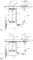
- Figs. 7 and 8 show another embodiment with several grinding heads 33a, 33b, which are similar to the example from Fig. 2 can be tilted around two axes.
- the upper part of the Fig.7 The device shown (support plate 51, motor 31, actuator 2) is the same as in the example from Fig. 2 and 6 and reference is made to the above explanations.
- the device has Fig.7
- an assembly 70 with two or more grinding heads 33a, 33b is formed.
- the entire assembly 70 is coupled to the actuator 2 by means of a universal joint 60.
- one end of the universal joint 60 is mounted on a support plate 52, which in turn is rigidly connected to the lower end of the actuator 2.
- the other end of the universal joint 60 is mounted on a housing 71 of the assembly 70.
- the intersection point of the tilting axes of the universal joint 60 is at a vertical distance d v below the lower end of the flexible shaft 544; in this example too, it is desirable to arrange the universal joint 60 as far down as possible. Since, in contrast to the example from Fig. 2 If it is possible to arrange the universal joint 60 between the grinding heads in the case of several grinding heads, the joint can be designed more simply and no gimbal suspension is required as in Fig. 2 necessary.
- the axes of rotation of the drive shafts of the grinding heads 33a and 33b are designated C and D, respectively.
- a pulley 73a is mounted on the drive shaft of the grinding head 33a
- a pulley 73b is mounted on the drive shaft of the grinding head 33b.
- a third grinding head 33c with a pulley 73c is provided for the actuator 2 (not shown), the rotation axes of the three grinding heads being offset by 120° in relation to the longitudinal axis A of the actuator 2.
- any other transmission e.g. a gear transmission
- the transmission such as the belt drive in the examples described here, is used to transmit the mechanical power. How this transmission of the mechanical power is implemented in concrete terms is not of particular relevance.
- a shaft (rotation axis B) is mounted (see Fig.7 , bearing 72) which is connected to the motor shaft 310 by the flexible shaft 544.
- Another pulley 74 is mounted on the shaft with the rotation axis B, and a belt 75 connects the pulley 74 (driven by the motor 31 via the flexible shaft 544) to the pulleys 73a, 73b (and possibly 73c), so that the drive shafts of all grinding heads 33a, 33b (and possibly 33c) are driven via the belt.
- the vertical distance a between the assembly 70 (in the non-tilted normal position as in Fig.7 shown) and the upper support plate 51 depends on the deflection of the actuator 2. Both a change in the distance a and a tilting of the assembly 70 can be compensated by the flexible shaft 544.
- Fig.8 shows the device from Fig.7 with tilted assembly 70.
- Fig.9 illustrates a further embodiment in which the device is not mounted on a manipulator but is stationary.
- the workpiece can be positioned relative to the grinding wheel using a manipulator.
- the carrier plate 51 is mounted in a fixed position.
- the carrier plate 51 can be seen as part of any supporting structure (this applies to all embodiments) or can be mounted on any supporting structure.
- a housing, a tripod, etc. can be considered as a supporting structure.
- the carrier plate 51 can also be seen as part of the actuator 2 (this also applies to all embodiments).
- the actuator 2 directly or indirectly couples the carrier plate 51 to a processing head 33 (grinding head), which in the simplest case contains a rotatably mounted shaft on which the processing tool such as the grinding wheel 32 is mounted.
- a processing head 33 grinding head
- the workpiece 5 is positioned (eg by means of a manipulator) and the actuator 2 regulates the contact force as described above or, if there is no contact with the workpiece, presses against an end stop with a defined force (set by means of force control).
- the motor 31 is also mounted stationary (eg on the same supporting structure as the actuator 2) and thus has a variable relative position to the grinding head 33, which can be compensated via a flexible shaft 544 (in the same way as in the other embodiments described here).
- the embodiments described above, in which the (at least one) grinding head is tiltably mounted on the actuator by means of a cardanic suspension or a universal joint can also be operated stationary, while the workpiece is positioned by means of a manipulator.
- the device has a carrier plate for mounting the device on a manipulator (see e.g. Fig. 2 , 5 and 7 , carrier plate 51), a motor, a linear actuator, and (at least) one processing head (see e.g. Fig. 2 , 5 , grinding head 33 or Fig.7 , grinding heads 33a, 33b).
- the processing head is coupled (directly or indirectly) to the carrier plate by means of the linear actuator and has a drive shaft (see e.g. Fig.
- the device also has a flexible shaft which couples a motor shaft of the motor to the drive shaft of the machining head directly or indirectly (e.g. via an additional telescopic shaft).
- the carrier plate does not necessarily have to be mounted on a manipulator.
- the workpiece to be machined can be positioned by a manipulator; in this case, the carrier plate is stationary, for example part of a housing, a tripod or another supporting structure.
- the motor can be mounted on the same carrier plate as the actuator. However, this is not necessary due to the flexible shaft.
- the carrier plates are not necessarily flat plates, but can represent any supporting structure.
- a universal joint is used to mechanically couple the (at least one) processing head to the linear actuator.
- a two-axis tilting of the processing head is enabled.
- the universal joint is realized by a cardanic suspension, in the example from Figs. 7 and 8 a simple universal joint (cardan joint) is used.
- cardan joint a simple universal joint (cardan joint) is used.
- the device has a support structure that is mounted on one end of the linear actuator, whereas the other end of the linear actuator is mounted on the support plate.
- the universal joint can form a cardanic suspension by means of which the processing head is mounted on the support structure.
- the support structure can be another support plate (see e.g. Fig. 2-4 , base plate 52 with lateral legs 521, 522).
- the support structure can have an opening through which the processing head or the flexible shaft is guided (see. Fig.3 , grinding wheel 32 is below the carrier plate 52 and the flexible shaft is coupled to the grinding head 33 above the carrier plate 52).
- the two tilting axes of the universal joint are spaced from a top of the machining head (see Fig.
- the machining head can have a gear (see Fig.3 , gear 34) so that a rotation axis of the rotatable tool and a rotation axis of the drive shaft are axially offset (see Fig. 2 , distance d H ).
- several processing heads are mounted on the support structure and the support structure is coupled to the linear actuator via a universal joint.
- the universal joint enables tilting about two tilting axes, which according to a special embodiment can intersect at an intersection point through which the longitudinal axis of the actuator also runs.
- the universal joint is arranged within the housing of the assembly, and the grinding heads are arranged around the universal joint.
- three grinding heads can be arranged around the universal joint, each offset by 120° (with respect to the longitudinal axis of the actuator and the joint).
- the tilting axes of the universal joint lie in a plane that runs through the grinding heads and is therefore as close as possible to the workpiece surface.
- a shaft is mounted by means of a bearing, which is connected to the flexible shaft and can thus be driven by the motor.
- This shaft is connected to the drive shafts of the grinding heads via a gear, such as a belt drive.
- the flexible shaft allows the motor to be coupled to the grinding heads, even if the relative position of the grinding heads to the motor is variable. Changes in the relative position can be compensated by the flexible shaft.
- the axes of rotation of the motor shaft and grinding head do not have to be parallel, and can even form an angle of approximately 90° (see Fig.5 ). To avoid excessive bending of the flexible shaft, it can be combined with a telescopic shaft (see Fig. 2 ).
Landscapes
- Engineering & Computer Science (AREA)
- Mechanical Engineering (AREA)
- Robotics (AREA)
- Manipulator (AREA)
- Constituent Portions Of Griding Lathes, Driving, Sensing And Control (AREA)
- Finish Polishing, Edge Sharpening, And Grinding By Specific Grinding Devices (AREA)
Applications Claiming Priority (2)
| Application Number | Priority Date | Filing Date | Title |
|---|---|---|---|
| DE102019110421 | 2019-04-19 | ||
| PCT/EP2020/060818 WO2020212552A1 (de) | 2019-04-19 | 2020-04-17 | Vorrichtung zum robotergestützten bearbeiten von oberflächen |
Publications (3)
| Publication Number | Publication Date |
|---|---|
| EP3956102A1 EP3956102A1 (de) | 2022-02-23 |
| EP3956102C0 EP3956102C0 (de) | 2024-09-25 |
| EP3956102B1 true EP3956102B1 (de) | 2024-09-25 |
Family
ID=70391106
Family Applications (1)
| Application Number | Title | Priority Date | Filing Date |
|---|---|---|---|
| EP20720785.3A Active EP3956102B1 (de) | 2019-04-19 | 2020-04-17 | Vorrichtung zum bearbeiten von oberflächen |
Country Status (7)
| Country | Link |
|---|---|
| US (1) | US20220193857A1 (https=) |
| EP (1) | EP3956102B1 (https=) |
| JP (1) | JP7685955B2 (https=) |
| KR (1) | KR102838341B1 (https=) |
| CN (1) | CN113710420B (https=) |
| DE (1) | DE102020110492A1 (https=) |
| WO (1) | WO2020212552A1 (https=) |
Families Citing this family (8)
| Publication number | Priority date | Publication date | Assignee | Title |
|---|---|---|---|---|
| US20220379430A1 (en) * | 2019-11-07 | 2022-12-01 | Mirka Ltd | Apparatus comprising an abrading head |
| WO2022085587A1 (ja) | 2020-10-22 | 2022-04-28 | ファナック株式会社 | ロボットプログラミング装置、及びロボットプログラミング方法 |
| FI20215948A1 (en) * | 2021-09-09 | 2023-03-10 | Mirka Ltd | Method and apparatus for surface processing |
| CN115319769B (zh) * | 2022-09-06 | 2025-05-16 | 安徽新境界自动化技术有限公司 | 一种基于可变刚度的柔性打磨机器人 |
| CN116810594B (zh) * | 2023-07-19 | 2025-09-30 | 哈尔滨工程大学 | 一种深水打磨器 |
| CN117381340A (zh) * | 2023-08-18 | 2024-01-12 | 宁波锦辉光学科技有限公司 | 一种激光面罩光学面模具的加工方法 |
| KR102913378B1 (ko) * | 2023-12-28 | 2026-01-16 | (주)정산 | 선박용 프로펠라 자동연마장치 |
| DE102024000879A1 (de) * | 2024-03-18 | 2025-09-18 | Hochschule für angewandte Wissenschaften München, Körperschaft des öffentlichen Rechts | Endeffektor mit optimierter Nachführung eines Werkzeugs und Verfahren zum Bearbeiten einer Werkstückoberfläche |
Family Cites Families (17)
| Publication number | Priority date | Publication date | Assignee | Title |
|---|---|---|---|---|
| JPS61159366A (ja) * | 1984-12-27 | 1986-07-19 | Toshiba Corp | 研削ロボツト |
| FR2591522B1 (fr) * | 1985-12-13 | 1988-04-08 | Syspro | Dispositif de disjonction pour bras de robot |
| DE3609441A1 (de) | 1986-03-20 | 1987-09-24 | Bosch Gmbh Robert | Exzenterschleifer mit einer vorrichtung zum veraendern der schleifbewegung |
| EP0492014B1 (en) * | 1990-12-28 | 1996-03-20 | Aiko Engineering Co. Ltd. | Automatic grinding apparatus |
| DE4223107A1 (de) * | 1992-07-14 | 1994-01-20 | Bosch Gmbh Robert | Flächenschleifmaschine |
| DE9404159U1 (de) * | 1994-03-11 | 1994-09-01 | Riesle, Norbert, 79279 Vörstetten | Hilfsgerät zum Bearbeiten, insbesondere zum Verbinden von Teilen |
| US6244943B1 (en) * | 1998-12-30 | 2001-06-12 | Guther Bohler Gmbh | Surface-processing apparatus |
| CN1292313A (zh) * | 1999-10-10 | 2001-04-25 | 周毓明 | 一种钻夹头可与驱动电机分离的电钻 |
| US6753495B2 (en) * | 2001-05-31 | 2004-06-22 | Murray Forlong | Apparatus and methods for control of a material processing device |
| DE10200381A1 (de) * | 2002-01-08 | 2003-07-17 | Guenther Boehler Gmbh | Vorrichtung zur Bearbeitung von Oberflächen |
| JP2004322219A (ja) * | 2003-04-21 | 2004-11-18 | Miyota Kk | フレキシブル加工ヘッドユニット、及びそれを用いた研磨装置 |
| CN203751914U (zh) * | 2013-12-31 | 2014-08-06 | 山佳卫 | 双面高速磨光机 |
| DE102016104412B3 (de) * | 2016-03-10 | 2017-08-17 | Areva Gmbh | Manipulator und Manipulatoreinheit |
| DE102016118173A1 (de) * | 2016-09-26 | 2018-03-29 | Ferrobotics Compliant Robot Technology Gmbh | Werkzeugmaschine zum robotergestützten bearbeiten von oberflächen |
| CN108115525A (zh) * | 2018-02-07 | 2018-06-05 | 大连理工大学 | 一种内表面在线检测和修整一体化工具 |
| CN109366323A (zh) | 2018-11-26 | 2019-02-22 | 湖南劳动人事职业学院 | 一种用于环形均布圆孔的多头打磨抛光机 |
| JP2021159366A (ja) * | 2020-03-31 | 2021-10-11 | 株式会社三洋物産 | 遊技機 |
-
2020
- 2020-04-17 WO PCT/EP2020/060818 patent/WO2020212552A1/de not_active Ceased
- 2020-04-17 EP EP20720785.3A patent/EP3956102B1/de active Active
- 2020-04-17 US US17/604,586 patent/US20220193857A1/en active Pending
- 2020-04-17 DE DE102020110492.8A patent/DE102020110492A1/de active Pending
- 2020-04-17 CN CN202080029865.4A patent/CN113710420B/zh active Active
- 2020-04-17 KR KR1020217033998A patent/KR102838341B1/ko active Active
- 2020-04-17 JP JP2021561764A patent/JP7685955B2/ja active Active
Also Published As
| Publication number | Publication date |
|---|---|
| EP3956102C0 (de) | 2024-09-25 |
| DE102020110492A1 (de) | 2020-10-22 |
| WO2020212552A1 (de) | 2020-10-22 |
| JP7685955B2 (ja) | 2025-05-30 |
| KR20210151108A (ko) | 2021-12-13 |
| US20220193857A1 (en) | 2022-06-23 |
| CN113710420A (zh) | 2021-11-26 |
| CN113710420B (zh) | 2024-08-27 |
| JP2022530857A (ja) | 2022-07-04 |
| KR102838341B1 (ko) | 2025-07-23 |
| EP3956102A1 (de) | 2022-02-23 |
Similar Documents
| Publication | Publication Date | Title |
|---|---|---|
| EP3956102B1 (de) | Vorrichtung zum bearbeiten von oberflächen | |
| EP3325214B1 (de) | Werkzeugmaschine zum robotergestützten bearbeiten von oberflächen | |
| EP3765239B1 (de) | Drehzahlsteuerung beim robotergestützten schleifen | |
| DE102010007631B4 (de) | Parallelroboter mit einem Handgelenkabschnitt mit drei Freiheitsgraden | |
| EP3439836B1 (de) | Robotergestützte schleifvorrichtung | |
| DE69116901T2 (de) | Robotersteuerung | |
| EP3481605B1 (de) | Verfahren und system zum automatischen wechseln von wellen | |
| EP3703906B1 (de) | Robotergestützte schleifvorrichtung mit integrierter wartungseinheit | |
| EP2740563B1 (de) | Bearbeitungseinrichtung, Bearbeitungsmaschine und Verfahren zum Bewegen eines Bearbeitungskopfs | |
| EP3612350B1 (de) | Schleifmaschine zum robotergestützten schleifen | |
| DE102010006155A1 (de) | Parallelroboter | |
| EP3980227A2 (de) | Ausgleich von lagetoleranzen beim der robotergestützten oberflächenbearbeitung | |
| DE102015119589B4 (de) | Vorrichtung und Verfahren zum robotergestützen Rollfalzen | |
| EP3288712B1 (de) | Vorrichtung zur oberflächenbearbeitung | |
| EP4330558B1 (de) | Pneumatischer linearaktor | |
| WO2021063666A1 (de) | Flurgebundenes fahrzeug | |
| DE102007010580B4 (de) | Vorrichtung zur Bewegung einer Arbeitsplattform einer Bearbeitungsmaschine sowie Verfahren zur Steuerung einer Bewegungsbahn dieser Arbeitsplattform | |
| DE102019101579A1 (de) | Robotergestützte schleifvorrichtung mit integrierter wartungseinheit | |
| DE19938058B4 (de) | Bewegungseinrichtung zur Bewegung einer Halteeinrichtung | |
| EP3934862B1 (de) | Schnellspannsystem zur verbindung von werkzeugmaschinen mit einem roboter | |
| EP3697567A1 (de) | Absaugung für schleifwerkzeug mit radialbürstenscheibe | |
| DE102018120554A1 (de) | Werkzeugmaschine, Werkzeug und Steuerprogramm | |
| EP4592039B1 (de) | Manipulator und roboteraufbau | |
| EP1600252A2 (de) | Werkzeugantrieb, insbesondere zum automatischen Entgraten, Kantenbrechen oder Verputzen von Werkstücken |
Legal Events
| Date | Code | Title | Description |
|---|---|---|---|
| STAA | Information on the status of an ep patent application or granted ep patent |
Free format text: STATUS: UNKNOWN |
|
| STAA | Information on the status of an ep patent application or granted ep patent |
Free format text: STATUS: THE INTERNATIONAL PUBLICATION HAS BEEN MADE |
|
| PUAI | Public reference made under article 153(3) epc to a published international application that has entered the european phase |
Free format text: ORIGINAL CODE: 0009012 |
|
| STAA | Information on the status of an ep patent application or granted ep patent |
Free format text: STATUS: REQUEST FOR EXAMINATION WAS MADE |
|
| 17P | Request for examination filed |
Effective date: 20211117 |
|
| AK | Designated contracting states |
Kind code of ref document: A1 Designated state(s): AL AT BE BG CH CY CZ DE DK EE ES FI FR GB GR HR HU IE IS IT LI LT LU LV MC MK MT NL NO PL PT RO RS SE SI SK SM TR |
|
| DAV | Request for validation of the european patent (deleted) | ||
| DAX | Request for extension of the european patent (deleted) | ||
| GRAP | Despatch of communication of intention to grant a patent |
Free format text: ORIGINAL CODE: EPIDOSNIGR1 |
|
| STAA | Information on the status of an ep patent application or granted ep patent |
Free format text: STATUS: GRANT OF PATENT IS INTENDED |
|
| INTG | Intention to grant announced |
Effective date: 20240423 |
|
| GRAS | Grant fee paid |
Free format text: ORIGINAL CODE: EPIDOSNIGR3 |
|
| GRAA | (expected) grant |
Free format text: ORIGINAL CODE: 0009210 |
|
| STAA | Information on the status of an ep patent application or granted ep patent |
Free format text: STATUS: THE PATENT HAS BEEN GRANTED |
|
| AK | Designated contracting states |
Kind code of ref document: B1 Designated state(s): AL AT BE BG CH CY CZ DE DK EE ES FI FR GB GR HR HU IE IS IT LI LT LU LV MC MK MT NL NO PL PT RO RS SE SI SK SM TR |
|
| REG | Reference to a national code |
Ref country code: GB Ref legal event code: FG4D Free format text: NOT ENGLISH |
|
| REG | Reference to a national code |
Ref country code: CH Ref legal event code: EP |
|
| REG | Reference to a national code |
Ref country code: DE Ref legal event code: R096 Ref document number: 502020009327 Country of ref document: DE |
|
| REG | Reference to a national code |
Ref country code: IE Ref legal event code: FG4D Free format text: LANGUAGE OF EP DOCUMENT: GERMAN |
|
| U01 | Request for unitary effect filed |
Effective date: 20240927 |
|
| U07 | Unitary effect registered |
Designated state(s): AT BE BG DE DK EE FI FR IT LT LU LV MT NL PT RO SE SI Effective date: 20241024 |
|
| PG25 | Lapsed in a contracting state [announced via postgrant information from national office to epo] |
Ref country code: NO Free format text: LAPSE BECAUSE OF FAILURE TO SUBMIT A TRANSLATION OF THE DESCRIPTION OR TO PAY THE FEE WITHIN THE PRESCRIBED TIME-LIMIT Effective date: 20241225 |
|
| PG25 | Lapsed in a contracting state [announced via postgrant information from national office to epo] |
Ref country code: GR Free format text: LAPSE BECAUSE OF FAILURE TO SUBMIT A TRANSLATION OF THE DESCRIPTION OR TO PAY THE FEE WITHIN THE PRESCRIBED TIME-LIMIT Effective date: 20241226 |
|
| PG25 | Lapsed in a contracting state [announced via postgrant information from national office to epo] |
Ref country code: RS Free format text: LAPSE BECAUSE OF FAILURE TO SUBMIT A TRANSLATION OF THE DESCRIPTION OR TO PAY THE FEE WITHIN THE PRESCRIBED TIME-LIMIT Effective date: 20241225 |
|
| PG25 | Lapsed in a contracting state [announced via postgrant information from national office to epo] |
Ref country code: RS Free format text: LAPSE BECAUSE OF FAILURE TO SUBMIT A TRANSLATION OF THE DESCRIPTION OR TO PAY THE FEE WITHIN THE PRESCRIBED TIME-LIMIT Effective date: 20241225 Ref country code: NO Free format text: LAPSE BECAUSE OF FAILURE TO SUBMIT A TRANSLATION OF THE DESCRIPTION OR TO PAY THE FEE WITHIN THE PRESCRIBED TIME-LIMIT Effective date: 20241225 Ref country code: GR Free format text: LAPSE BECAUSE OF FAILURE TO SUBMIT A TRANSLATION OF THE DESCRIPTION OR TO PAY THE FEE WITHIN THE PRESCRIBED TIME-LIMIT Effective date: 20241226 |
|
| PG25 | Lapsed in a contracting state [announced via postgrant information from national office to epo] |
Ref country code: IS Free format text: LAPSE BECAUSE OF FAILURE TO SUBMIT A TRANSLATION OF THE DESCRIPTION OR TO PAY THE FEE WITHIN THE PRESCRIBED TIME-LIMIT Effective date: 20250125 |
|
| PG25 | Lapsed in a contracting state [announced via postgrant information from national office to epo] |
Ref country code: SM Free format text: LAPSE BECAUSE OF FAILURE TO SUBMIT A TRANSLATION OF THE DESCRIPTION OR TO PAY THE FEE WITHIN THE PRESCRIBED TIME-LIMIT Effective date: 20240925 |
|
| PG25 | Lapsed in a contracting state [announced via postgrant information from national office to epo] |
Ref country code: ES Free format text: LAPSE BECAUSE OF FAILURE TO SUBMIT A TRANSLATION OF THE DESCRIPTION OR TO PAY THE FEE WITHIN THE PRESCRIBED TIME-LIMIT Effective date: 20240925 |
|
| PG25 | Lapsed in a contracting state [announced via postgrant information from national office to epo] |
Ref country code: CZ Free format text: LAPSE BECAUSE OF FAILURE TO SUBMIT A TRANSLATION OF THE DESCRIPTION OR TO PAY THE FEE WITHIN THE PRESCRIBED TIME-LIMIT Effective date: 20240925 Ref country code: PL Free format text: LAPSE BECAUSE OF FAILURE TO SUBMIT A TRANSLATION OF THE DESCRIPTION OR TO PAY THE FEE WITHIN THE PRESCRIBED TIME-LIMIT Effective date: 20240925 |
|
| PG25 | Lapsed in a contracting state [announced via postgrant information from national office to epo] |
Ref country code: SK Free format text: LAPSE BECAUSE OF FAILURE TO SUBMIT A TRANSLATION OF THE DESCRIPTION OR TO PAY THE FEE WITHIN THE PRESCRIBED TIME-LIMIT Effective date: 20240925 |
|
| U21 | Renewal fee for the european patent with unitary effect paid with additional fee |
Year of fee payment: 6 Effective date: 20250603 |
|
| PLBE | No opposition filed within time limit |
Free format text: ORIGINAL CODE: 0009261 |
|
| STAA | Information on the status of an ep patent application or granted ep patent |
Free format text: STATUS: NO OPPOSITION FILED WITHIN TIME LIMIT |
|
| 26N | No opposition filed |
Effective date: 20250626 |
|
| REG | Reference to a national code |
Ref country code: CH Ref legal event code: H13 Free format text: ST27 STATUS EVENT CODE: U-0-0-H10-H13 (AS PROVIDED BY THE NATIONAL OFFICE) Effective date: 20251125 |
|
| PG25 | Lapsed in a contracting state [announced via postgrant information from national office to epo] |
Ref country code: MC Free format text: LAPSE BECAUSE OF FAILURE TO SUBMIT A TRANSLATION OF THE DESCRIPTION OR TO PAY THE FEE WITHIN THE PRESCRIBED TIME-LIMIT Effective date: 20240925 |
|
| PG25 | Lapsed in a contracting state [announced via postgrant information from national office to epo] |
Ref country code: HR Free format text: LAPSE BECAUSE OF FAILURE TO SUBMIT A TRANSLATION OF THE DESCRIPTION OR TO PAY THE FEE WITHIN THE PRESCRIBED TIME-LIMIT Effective date: 20240925 |
|
| PG25 | Lapsed in a contracting state [announced via postgrant information from national office to epo] |
Ref country code: CH Free format text: LAPSE BECAUSE OF NON-PAYMENT OF DUE FEES Effective date: 20250430 |
|
| PGFP | Annual fee paid to national office [announced via postgrant information from national office to epo] |
Ref country code: GB Payment date: 20260327 Year of fee payment: 7 |
|
| PG25 | Lapsed in a contracting state [announced via postgrant information from national office to epo] |
Ref country code: IE Free format text: LAPSE BECAUSE OF NON-PAYMENT OF DUE FEES Effective date: 20250417 |
|
| U20 | Renewal fee for the european patent with unitary effect paid |
Year of fee payment: 7 Effective date: 20260319 |