EP3954852A1 - Führungsvorrichtung und möbel - Google Patents
Führungsvorrichtung und möbel Download PDFInfo
- Publication number
- EP3954852A1 EP3954852A1 EP21184758.7A EP21184758A EP3954852A1 EP 3954852 A1 EP3954852 A1 EP 3954852A1 EP 21184758 A EP21184758 A EP 21184758A EP 3954852 A1 EP3954852 A1 EP 3954852A1
- Authority
- EP
- European Patent Office
- Prior art keywords
- guide rail
- positioning means
- marking
- guide device
- mounting element
- Prior art date
- Legal status (The legal status is an assumption and is not a legal conclusion. Google has not performed a legal analysis and makes no representation as to the accuracy of the status listed.)
- Granted
Links
- 238000004049 embossing Methods 0.000 claims description 5
- 239000012190 activator Substances 0.000 description 8
- 239000003550 marker Substances 0.000 description 4
- 235000001674 Agaricus brunnescens Nutrition 0.000 description 1
- 238000010276 construction Methods 0.000 description 1
- 238000002372 labelling Methods 0.000 description 1
- 238000004519 manufacturing process Methods 0.000 description 1
- 239000002184 metal Substances 0.000 description 1
Images


Classifications
-
- E—FIXED CONSTRUCTIONS
- E05—LOCKS; KEYS; WINDOW OR DOOR FITTINGS; SAFES
- E05D—HINGES OR SUSPENSION DEVICES FOR DOORS, WINDOWS OR WINGS
- E05D15/00—Suspension arrangements for wings
- E05D15/06—Suspension arrangements for wings for wings sliding horizontally more or less in their own plane
- E05D15/08—Suspension arrangements for wings for wings sliding horizontally more or less in their own plane consisting of two or more independent parts movable each in its own guides
-
- E—FIXED CONSTRUCTIONS
- E05—LOCKS; KEYS; WINDOW OR DOOR FITTINGS; SAFES
- E05D—HINGES OR SUSPENSION DEVICES FOR DOORS, WINDOWS OR WINGS
- E05D15/00—Suspension arrangements for wings
- E05D15/06—Suspension arrangements for wings for wings sliding horizontally more or less in their own plane
- E05D15/0621—Details, e.g. suspension or supporting guides
- E05D15/0626—Details, e.g. suspension or supporting guides for wings suspended at the top
- E05D15/0652—Tracks
-
- E—FIXED CONSTRUCTIONS
- E05—LOCKS; KEYS; WINDOW OR DOOR FITTINGS; SAFES
- E05F—DEVICES FOR MOVING WINGS INTO OPEN OR CLOSED POSITION; CHECKS FOR WINGS; WING FITTINGS NOT OTHERWISE PROVIDED FOR, CONCERNED WITH THE FUNCTIONING OF THE WING
- E05F1/00—Closers or openers for wings, not otherwise provided for in this subclass
- E05F1/08—Closers or openers for wings, not otherwise provided for in this subclass spring-actuated, e.g. for horizontally sliding wings
- E05F1/16—Closers or openers for wings, not otherwise provided for in this subclass spring-actuated, e.g. for horizontally sliding wings for sliding wings
-
- E—FIXED CONSTRUCTIONS
- E05—LOCKS; KEYS; WINDOW OR DOOR FITTINGS; SAFES
- E05F—DEVICES FOR MOVING WINGS INTO OPEN OR CLOSED POSITION; CHECKS FOR WINGS; WING FITTINGS NOT OTHERWISE PROVIDED FOR, CONCERNED WITH THE FUNCTIONING OF THE WING
- E05F5/00—Braking devices, e.g. checks; Stops; Buffers
- E05F5/003—Braking devices, e.g. checks; Stops; Buffers for sliding wings
-
- E—FIXED CONSTRUCTIONS
- E05—LOCKS; KEYS; WINDOW OR DOOR FITTINGS; SAFES
- E05Y—INDEXING SCHEME RELATING TO HINGES OR OTHER SUSPENSION DEVICES FOR DOORS, WINDOWS OR WINGS AND DEVICES FOR MOVING WINGS INTO OPEN OR CLOSED POSITION, CHECKS FOR WINGS AND WING FITTINGS NOT OTHERWISE PROVIDED FOR, CONCERNED WITH THE FUNCTIONING OF THE WING
- E05Y2201/00—Constructional elements; Accessories therefore
- E05Y2201/20—Brakes; Disengaging means, e.g. clutches; Holders, e.g. locks; Stops; Accessories therefore
- E05Y2201/218—Holders
-
- E—FIXED CONSTRUCTIONS
- E05—LOCKS; KEYS; WINDOW OR DOOR FITTINGS; SAFES
- E05Y—INDEXING SCHEME RELATING TO HINGES OR OTHER SUSPENSION DEVICES FOR DOORS, WINDOWS OR WINGS AND DEVICES FOR MOVING WINGS INTO OPEN OR CLOSED POSITION, CHECKS FOR WINGS AND WING FITTINGS NOT OTHERWISE PROVIDED FOR, CONCERNED WITH THE FUNCTIONING OF THE WING
- E05Y2600/00—Mounting or coupling arrangements for elements provided for in this subclass
- E05Y2600/50—Mounting methods; Positioning
- E05Y2600/52—Toolless
- E05Y2600/528—Hooking, e.g. using bayonets; Locking
-
- E—FIXED CONSTRUCTIONS
- E05—LOCKS; KEYS; WINDOW OR DOOR FITTINGS; SAFES
- E05Y—INDEXING SCHEME RELATING TO HINGES OR OTHER SUSPENSION DEVICES FOR DOORS, WINDOWS OR WINGS AND DEVICES FOR MOVING WINGS INTO OPEN OR CLOSED POSITION, CHECKS FOR WINGS AND WING FITTINGS NOT OTHERWISE PROVIDED FOR, CONCERNED WITH THE FUNCTIONING OF THE WING
- E05Y2600/00—Mounting or coupling arrangements for elements provided for in this subclass
- E05Y2600/50—Mounting methods; Positioning
- E05Y2600/52—Toolless
- E05Y2600/53—Snapping
-
- E—FIXED CONSTRUCTIONS
- E05—LOCKS; KEYS; WINDOW OR DOOR FITTINGS; SAFES
- E05Y—INDEXING SCHEME RELATING TO HINGES OR OTHER SUSPENSION DEVICES FOR DOORS, WINDOWS OR WINGS AND DEVICES FOR MOVING WINGS INTO OPEN OR CLOSED POSITION, CHECKS FOR WINGS AND WING FITTINGS NOT OTHERWISE PROVIDED FOR, CONCERNED WITH THE FUNCTIONING OF THE WING
- E05Y2600/00—Mounting or coupling arrangements for elements provided for in this subclass
- E05Y2600/50—Mounting methods; Positioning
- E05Y2600/56—Positioning or pre-mounting
-
- E—FIXED CONSTRUCTIONS
- E05—LOCKS; KEYS; WINDOW OR DOOR FITTINGS; SAFES
- E05Y—INDEXING SCHEME RELATING TO HINGES OR OTHER SUSPENSION DEVICES FOR DOORS, WINDOWS OR WINGS AND DEVICES FOR MOVING WINGS INTO OPEN OR CLOSED POSITION, CHECKS FOR WINGS AND WING FITTINGS NOT OTHERWISE PROVIDED FOR, CONCERNED WITH THE FUNCTIONING OF THE WING
- E05Y2600/00—Mounting or coupling arrangements for elements provided for in this subclass
- E05Y2600/60—Mounting or coupling members; Accessories therefore
- E05Y2600/626—Plates or brackets
-
- E—FIXED CONSTRUCTIONS
- E05—LOCKS; KEYS; WINDOW OR DOOR FITTINGS; SAFES
- E05Y—INDEXING SCHEME RELATING TO HINGES OR OTHER SUSPENSION DEVICES FOR DOORS, WINDOWS OR WINGS AND DEVICES FOR MOVING WINGS INTO OPEN OR CLOSED POSITION, CHECKS FOR WINGS AND WING FITTINGS NOT OTHERWISE PROVIDED FOR, CONCERNED WITH THE FUNCTIONING OF THE WING
- E05Y2800/00—Details, accessories and auxiliary operations not otherwise provided for
- E05Y2800/20—Combinations of elements
- E05Y2800/23—Combinations of elements of elements of different categories
- E05Y2800/24—Combinations of elements of elements of different categories of springs and brakes
-
- E—FIXED CONSTRUCTIONS
- E05—LOCKS; KEYS; WINDOW OR DOOR FITTINGS; SAFES
- E05Y—INDEXING SCHEME RELATING TO HINGES OR OTHER SUSPENSION DEVICES FOR DOORS, WINDOWS OR WINGS AND DEVICES FOR MOVING WINGS INTO OPEN OR CLOSED POSITION, CHECKS FOR WINGS AND WING FITTINGS NOT OTHERWISE PROVIDED FOR, CONCERNED WITH THE FUNCTIONING OF THE WING
- E05Y2900/00—Application of doors, windows, wings or fittings thereof
- E05Y2900/20—Application of doors, windows, wings or fittings thereof for furnitures, e.g. cabinets
Definitions
- the present invention relates to a guide device for a sliding door system with a guide rail on which at least three sliding doors are held so that they can be moved via running parts, each sliding door being able to be moved via at least one running part with rollers along a track on the guide rail and the guide rail having at least two parallel tracks, at least one positioning means in the form of a latching element or a self-closing mechanism being provided on the guide rail in order to position one of the sliding doors in a predetermined position along the guide rail, and a piece of furniture.
- the DE 10 2018 112 021 A1 discloses a guide device for a sliding door, in which a mounting part is inserted on the front side of a guide rail, on which several mounting elements are designed for fixing a stop or a self-closing mechanism in order to hold a running part and thus a sliding door in a predetermined position.
- the arrangement of such positioning means in a central area is complex, since the position of a central sliding door can vary depending on the design of the furniture.
- To mount a central positioning means the position must first be calculated according to instructions and then the positioning means must be mounted exactly. Errors can occur in this regard, which affects the position of the sliding door in an open or closed position.
- the EP 3 358 115 B1 attaching a door marker to a door leaf and aligning a profile sheet to the door marker to specify the position of the door leaf. This assembly is also comparatively complex.
- At least one positioning means in the form of a latching element or a self-closing mechanism is provided in order to position one of the sliding doors in a predetermined position along the guide rail, with at least one marking being provided on the guide rail at a distance from the front ends of the guide rail and the at least a positioning means can be aligned via an identification on the marking and is fixed on the guide rail.
- the guide rail can be used during assembly to align the positioning means, which is fixed directly or indirectly to the guide rail. This reduces the susceptibility to errors during assembly and leads to a more precise positioning of the sliding doors by the at least one positioning means.
- a mounting element is preferably fixed to the guide rail, on which the marking is arranged and on which at least one of the positioning means is fixed.
- the mounting element can thus be aligned via the marking and fixed to the guide rail, so that one or more positioning means can be fixed to the mounting element.
- Preferably two positioning means are fixed on opposite sides of the mounting element.
- the marking on the mounting element can be in the form of a projection, recess, embossing, color marking or other marking means in order to be able to align the mounting element relative to a marking on the guide rail.
- the mounting element preferably comprises at least one web, in particular two aligned webs, on which a plurality of mounting points for fixing a positioning means are formed.
- Each assembly point can be designed as a receptacle on which a positioning means can be fixed via a clamping element.
- a different mechanical fixing of the positioning means at a mounting point is also possible, for example using pins, projections, latching elements or clamping devices.
- the positioning means can be pre-fixed to the mounting element by a projection formed thereon, which engages in a recess of the mounting element in a form-fitting manner, in order to facilitate handling.
- the positioning means can be easily mounted and aligned, with the provision of several mounting points on the web enabling different positioning of the positioning means on the mounting element and thus of the sliding doors, depending on the structure of the furniture.
- a spacing with a predetermined grid dimension or an exact flushness of sliding doors that can be moved parallel to one another can be produced, as desired.
- the mounting element is preferably designed symmetrically to a central plane, so that errors caused by incorrect positioning of the mounting element are avoided.
- the guide rail preferably comprises at least one groove adjacent to a track into which the mounting element and/or the positioning means is inserted.
- the positioning means can be designed as a simple latching element on which an activator, for example a web or a projection, which is connected to the sliding door, is latched.
- the positioning means can also be embodied as a self-closing mechanism, in which a driver can be moved along a guideway and is prestressed in a direction of retraction by an energy accumulator, in particular a spring. The sliding door can then be moved into a predetermined closed or open position via the driver.
- the marking on the guide rail can be arranged in the middle in the longitudinal direction.
- the middle position can be easily calculated and marked, so that the mounting element can be fixed in this middle position, on which the positioning means are then fixed in the desired position.
- the marking on the guide rail can be in the form of a projection, recess, embossing, color marking or other identification means.
- the guide device according to the invention is preferably used in a piece of furniture in which the guide rail is fixed to a top panel of the furniture body.
- the guide device can also be used for room dividers or other sliding door systems.
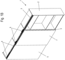
- a piece of furniture 1 comprises a furniture body 2 and is designed as a cabinet.
- a guide rail 3 is fixed to a top panel of the furniture carcass 2 in order to keep sliding doors 5 and 7 movable.
- Two rear sliding doors 5 are provided, which can be moved along the guide rail 3 via running parts 4, and a front sliding door 7, which can be moved via running parts 6 in front of the plane of the rear sliding doors 5.
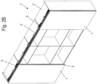
- FIG. 2A and 2 B a modified piece of furniture 1' is shown in which four sliding doors 5 and 7 are provided on a piece of furniture 2' instead of three sliding doors 5 and 7, with two rear sliding doors 5 and two front sliding doors 7 being provided.
- the rear sliding doors 5 are running parts 4 and the front sliding doors 7 can be moved via running parts 6 along the guide rail 3', which is slightly longer than in FIG figure 1 .
- positioning means are provided. These positioning means can be formed at the ends of the guide rail 3 as shown in FIG DE 10 2018 112 021 A1 is revealed.
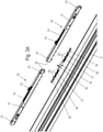
- each positioning means 10 comprises a housing 11 on which a driver 12 is mounted so that it can move along a guide track 13 .
- the driver 12 is prestressed in a retraction direction by a spring and preferably braked by a damper, so that a sliding door coupled to the driver 12 can be braked in a retraction area and held and positioned in the end position.
- a housing 11 of the self-closing mechanism is not fixed directly to the guide rail 3, but via a mounting element 15.
- at least one pre-fixing projection 14 and at least one clamping element 21, in this exemplary embodiment two clamping elements 21, are formed on the underside of the positioning means 10.
- the mounting element 15 comprises two webs at the end, on which mounting points 17, 18 and 19 are formed. Each of these assembly points 17, 18 and 19 serves as a receptacle for the at least one clamping element 21 on the positioning means 10, which is designed, for example, as a sliding block.
- the slot nut can be moved into the locked position from the top of the positioning means 10 by a tool, for example a wrench.
- a pre-fixing projection 14 embodied as a web is arranged on at least one end face of the positioning means 10 and can be inserted with a force fit and/or form-fit into one of several pre-fixing receptacles 22 embodied on the mounting element 15 .
- the positioning means 10 This enables the positioning means 10 to be pre-fixed to the mounting element 15 in order to ultimately be able to fix the complete structural unit to the guide rail 3 in an easy-to-mount manner.
- the pre-fixation recording 22, like the Figures 9, 10 and 11 show particularly well, be formed by two webs extending upwards, which create a free space for receiving the pre-fixing projection 14 .
- the structural unit consisting of the at least one positioning element 10 and mounting element 15 can be fastened to the guide rail 3 by the at least one sliding block arranged on the positioning means 10.
- the positioning means 10 has two sliding blocks and two positioning means 10 are arranged on the mounting element 15 .
- the number of these components can be varied depending on the desired application. Because the pre-fixing projection 14 can be inserted at various positions on the mounting element 15 and the clamping element 21 can be fixed at the mounting point 17, 18 or 19, when using a plurality of mounting elements 15 in planes parallel to one another, a spacing with a predetermined grid dimension is possible as desired, but of course also to realize an exact flushness of sliding doors 5 and 7 that can be moved parallel to one another.
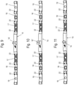
- FIG 3B the mounting element 15 is shown with two positioning means 10 in the mounted position, and it can be seen that these are essentially accommodated in a groove on the guide rail 3 and essentially only the driver 12 of the respective positioning means 10 protrudes upwards over the guide rail 3 .
- the two positioning means 10 are shown with the mounting element 15 in a mounted position.
- the mounting member 15 includes an upwardly protruding marker 16 in the form of a protrusion located centrally, with the mounting member 15 being formed symmetrically on either side of the marker 16 .
- On both sides of the assembly element 15 a web protrudes, on which, as described above, a positioning means 10 is pre-fixed by inserting the pre-fixing projection 14 into one of the pre-fixing receptacles 22 .
- a positioning means 10 is shown in engagement with an activator 20, which is coupled to the driver 12, so that the driver 12 can move the activator 20 into the end position by the force accumulator.
- the activator 20 is connected to the running part 6 on which the front sliding door 7 is held.
- the rear sliding doors 5 can also be coupled to a driver 12 by similar activators 20 .
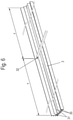
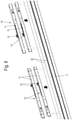
- a marking 32 is used to mount and align the positioning means 10 in a central area of the guide rail 3, as shown in figure 6 is shown. During assembly, the marking 32 is applied or drawn in, for example, centrally in the longitudinal direction of the guide rail 3, so that the two lengths x and y are of equal length. Optionally, the marking 32 can also be provided at a different point in a central area of the guide rail 3, depending on the design of the subsequent piece of furniture.
- the guide rail 3 comprises two tracks 30, which are formed, for example, by webs in the shape of mushroom heads, but can also have a different shape.
- a groove 31 is provided adjacent to the raceways 30 in each case, into which the positioning means 10 is later inserted.
- one or more assembly elements 15 are introduced or pushed into the guide rail 3, as is shown in figure 7 is shown.
- the marking 16 in the form of the projection serves to align the mounting element 15 so that the mounting element 15 with the marking 16 is fixed centrally in the guide rail 3 .
- the positioning means 10 can be fixed, as shown in figure 8 is shown.
- the position of the positioning means 10 can be varied, depending on how the subsequent piece of furniture should look, with the clamping element 21 designed as a sliding block on the positioning means 10 being selectively receivable in one of the assembly points 17, 18 or 19.
- the assembly points 17, 18, 19 are designed as receptacles in order to serve as clearance for the clamping element 21 after at least one pre-fixing projection 14 on the positioning means 10 has been inserted into the desired pre-fixing receptacle.
- two mounting elements 15 are mounted on the guide rail 3 so that four positioning means 10 can be fixed on the guide rail 3 .
- the number of positioning means 10 can of course be varied depending on the design of the guide rail 3 and the furniture.
- FIG 9 A modified mounting member 15 is shown in which an indicia 16' is in the form of a protrusion which is triangular in shape so that the apex of the triangle can be aligned along the mark 32 on the guide rail.
- a modified marking 16" is used in the mounting element 15, which is designed as a color marking or embossing in order to align the mounting element 15 with the marking 32.
- figure 11 shows the mounting element 15 with the identification 16, which is designed as a square cross-section projection.
- the markings 16, 16′ and 16′′ can be provided during the production of the mounting element 15.
- the marking 32 can optionally be attached by the manufacturer of the guide rail 3 or by the fitter in the guide rail 3, which is made, for example, from an extruded metal profile.
Abstract
Description
- Die vorliegende Erfindung betrifft eine Führungsvorrichtung für ein Schiebetürsystem mit einer Führungsschiene, an der über Laufteile mindestens drei Schiebetüren verfahrbar gehalten sind, wobei jede Schiebetür über mindestens ein Laufteil mit Rollen entlang einer Laufbahn an der Führungsschiene verfahrbar ist und die Führungsschiene mindestens zwei parallele Laufbahnen aufweist, wobei an der Führungsschiene mindestens ein Positionierungsmittel in Form eines Rastelementes oder eines Selbsteinzuges vorgesehen ist, um eine der Schiebetüren in einer vorbestimmten Position entlang der Führungsschiene zu positionieren, und ein Möbel.
- Die
DE 10 2018 112 021 A1 offenbart eine Führungsvorrichtung für eine Schiebetür, bei der an einer Führungsschiene stirnseitig ein Montageteil eingesteckt wird, an dem mehrere Montageelemente zur Fixierung eines Anschlages oder eines Selbsteinzuges ausgebildet sind, um ein Laufteil und somit eine Schiebetür in einer vorbestimmten Position zu halten. Die Anordnung solcher Positionierungsmittel in einem mittleren Bereich ist aufwändig, da die Position einer mittleren Schiebetür je nach Gestaltung des Möbels variieren kann. Zur Montage eines mittleren Positionierungsmittels muss zunächst gemäß einer Anleitung die Position berechnet und dann das Positionierungsmittel exakt montiert werden. Hierzu kann es zu Fehlern kommen, was die Position der Schiebetür in einer Öffnungs- oder Schließposition beeinflusst. - Zur Montage eines Einzugsdämpferbeschlages offenbart die
EP 3 358 115 B1 das Anbringen einer Türmarkierung an einem Türflügel und Ausrichten eines Profilbleches an der Türmarkierung, um die Position des Türflügels vorzugeben. Auch diese Montage ist vergleichsweise aufwändig. - Es ist daher Aufgabe der vorliegenden Erfindung, eine Führungsvorrichtung für ein Schiebetürsystem zu schaffen, das eine effektive Ausrichtung und Montage eines Positionierungsmittels in einem mittleren Bereich der Führungsschiene ermöglicht.
- Diese Aufgabe wird mit einer Führungsvorrichtung mit den Merkmalen des Anspruches 1 gelöst.
- Bei der erfindungsgemäßen Führungsvorrichtung ist mindestens ein Positionierungsmittel in Form eines Rastelementes oder eines Selbsteinzuges vorgesehen, um eine der Schiebetüren in einer vorbestimmten Position entlang der Führungsschiene zu positionieren, wobei an der Führungsschiene beabstandet von den stirnseitigen Enden der Führungsschiene mindestens eine Markierung vorgesehen ist und das mindestens eine Positionierungsmittel über eine Kennzeichnung an der Markierung ausrichtbar und an der Führungsschiene fixiert ist. Dadurch kann bei der Montage die Führungsschiene genutzt werden, um das Positionierungsmittel auszurichten, das mittelbar oder unmittelbar an der Führungsschiene fixiert wird. Dies verringert die Fehleranfälligkeit bei der Montage und führt zu einer exakteren Positionierung der Schiebetüren durch das mindestens eine Positionierungsmittel.
- Vorzugsweise ist an der Führungsschiene ein Montageelement festgelegt, an dem die Kennzeichnung angeordnet ist und an dem mindestens eines der Positionierungsmittel fixiert ist. Das Montageelement kann somit über die Kennzeichnung ausgerichtet und an der Führungsschiene fixiert werden, so dass an dem Montageelement eines oder mehrere Positionierungsmittel festgelegt werden können. Vorzugsweise sind zwei Positionierungsmittel an gegenüberliegenden Seiten des Montageelementes festgelegt. Die Kennzeichnung an dem Montageelement kann als Vorsprung, Aussparung, Prägung, Farbmarkierung oder anderes Kennzeichnungsmittel ausgebildet sein, um eine Ausrichtung des Montageelementes relativ zu einer Markierung an der Führungsschiene vornehmen zu können.
- Das Montageelement umfasst vorzugsweise mindestens einen Steg, insbesondere zwei fluchtende Stege, an denen mehrere Montagestellen zur Fixierung eines Positionierungsmittels ausgebildet sind. Jede Montagestelle kann dabei als Aufnahme ausgebildet sein, an der ein Positionierungsmittel über ein Klemmelement fixierbar ist. Auch eine andere mechanische Festlegung des Positionierungsmittels an einer Montagestelle ist möglich, beispielsweise über Stifte, Vorsprünge, Rastelemente oder Klemmeinrichtungen. Zudem kann das Positionierungsmittel durch einen daran ausgebildeten Vorsprung, der in eine Ausnehmung des Montageelementes formschlüssig eingreift, an dem Montageelement vorfixiert werden, um die Handhabung zu erleichtern. Durch Fixierung des Montageelementes kann somit eine einfache Montage und Ausrichtung der Positionierungsmittel erfolgen, wobei die Vorsehung mehrerer Montagestellen an dem Steg eine unterschiedliche Positionierung der Positionierungsmittel an dem Montageelement und somit der Schiebetüren ermöglicht, je nach Aufbau des Möbels. Somit lassen sich bei einer Anwendung von mehreren Montageelementen in zueinander parallelen Ebenen je nach Wunsch eine Beabstandung mit einem vorbestimmten Rastermaß oder eine exakte Bündigkeit zueinander parallel verfahrbarer Schiebetüren herstellen.
- Das Montageelement ist vorzugsweise zu einer Mittelebene symmetrisch ausgebildet, so dass Fehler durch eine falsche Positionierung des Montageelementes vermieden werden.
- Für einen kompakten Aufbau umfasst die Führungsschiene vorzugsweise mindestens eine Nut benachbart zu einer Laufbahn, in die das Montageelement und/oder das Positionierungsmittel eingefügt ist. Dadurch kann die Kraftübertragung von einem mit einer Schiebetür gekoppelten Aktivator in das Positionierungsmittel an der Führungsschiene erfolgen. Das Positionierungsmittel kann dabei als einfaches Rastelement ausgebildet sein, an dem ein Aktivator, beispielsweise ein Steg oder ein Vorsprung, der mit der Schiebetür verbunden ist, verrastet wird. Alternativ kann das Positionierungsmittel auch als Selbsteinzug ausgebildet sein, bei dem ein Mitnehmer entlang einer Führungsbahn verfahrbar ist und durch einen Kraftspeicher, insbesondere eine Feder, in eine Einzugsrichtung vorgespannt ist. Über den Mitnehmer kann die Schiebetür dann in eine vorbestimmte Schließ- oder Öffnungsposition bewegt werden.
- Für eine einfache Montage kann die Markierung an der Führungsschiene in Längsrichtung mittig angeordnet sein. Die mittlere Position lässt sich einfach berechnen und markieren, so dass in dieser mittigen Position das Montageelement festlegbar ist, an dem dann die Positionierungsmittel in der gewünschten Position fixiert werden. Die Markierung an der Führungsschiene kann dabei als Vorsprung, Aussparung, Prägung, Farbmarkierung oder anderes Kennzeichnungsmittel ausgebildet sein.
- Die erfindungsgemäße Führungsvorrichtung wird vorzugsweise bei einem Möbel eingesetzt, bei dem die Führungsschiene an einem Oberboden des Möbelkorpus fixiert ist. Alternativ kann die Führungsvorrichtung aber auch für Raumteiler oder andere Schiebetürsysteme eingesetzt werden.
- Die Erfindung wird nachfolgend anhand mehrerer Ausführungsbeispiele mit Bezug auf die beigefügten Zeichnungen näher erläutert. Es zeigen:
- Figuren 1A und 1B
- zwei Ansichten eines ersten Ausführungsbeispiels eines Möbels mit einer erfindungsgemäßen Führungsvorrichtung;
- Figuren 2A und 2B
- zwei Ansichten eines zweiten Ausführungsbeispiels eines Möbels mit einer erfindungsgemäßen Führungsvorrichtung;
- Figuren 3A und 3B
- zwei Detailansichten der Führungsvorrichtung bei der Montage;
- Figur 4
- eine perspektivische Ansicht des Montageelementes mit zwei Positionierungsmitteln;
- Figur 5
- eine Detailansicht eines Positionierungsmittels in Eingriff mit einem Aktivator einer Schiebetür;
- Figur 6
- eine Ansicht der Führungsschiene der Führungsvorrichtung bei der Montage;
- Figur 7
- eine Ansicht der Führungsschiene bei der Montage von Montageelementen;
- Figur 8
- eine Ansicht der Führungsschiene bei der Montage von Positionierungsmitteln an den Montageelementen, und
- Figuren 9 bis 11
- mehrere Ansichten unterschiedlicher Montageelemente.
- Ein Möbel 1 umfasst einen Möbelkorpus 2 und ist als Schrankmöbel ausgebildet. An einem Oberboden des Möbelkorpus 2 ist eine Führungsschiene 3 fixiert, um Schiebetüren 5 und 7 verfahrbar zu halten. Dabei sind zwei hintere Schiebetüren 5 vorgesehen, die über Laufteile 4 entlang der Führungsschiene 3 verfahrbar sind, und eine vordere Schiebetür 7, die vor der Ebene der hinteren Schiebetüren 5 über Laufteile 6 bewegbar ist.
- In den
Figuren 2A und2B ist ein modifiziertes Möbel 1' gezeigt, bei dem an einem Möbelkorpus 2' statt drei Schiebetüren 5 und 7 vier Schiebetüren 5 und 7 vorgesehen sind, wobei zwei hintere Schiebetüren 5 und zwei vordere Schiebetüren 7 vorgesehen sind. Die hinteren Schiebetüren 5 sind über Laufteile 4 und die vorderen Schiebetüren 7 sind über Laufteile 6 entlang der Führungsschiene 3' verfahrbar, die etwas länger ausgebildet ist als inFigur 1 . - Um die Schiebetüren 5 und 7 in bestimmten Positionen entlang der Führungsschiene 3 positionieren oder anhalten zu können, sind Positionierungsmittel vorgesehen. Diese Positionierungsmittel können endseitig an der Führungsschiene 3 so ausgebildet sein, wie dies in der
DE 10 2018 112 021 A1 offenbart ist. - In den
Figuren 3A und3B ist die Führungsschiene 3 in einem mittleren Bereich gezeigt, in dem Positionierungsmittel 10 in Form eines Selbsteinzuges fixiert werden. Jedes Positionierungsmittel 10 umfasst ein Gehäuse 11, an dem ein Mitnehmer 12 entlang einer Führungsbahn 13 verfahrbar gelagert ist. Der Mitnehmer 12 ist über eine Feder in eine Einzugsrichtung vorgespannt und vorzugsweise über einen Dämpfer abgebremst, so dass eine mit dem Mitnehmer 12 gekoppelte Schiebetür in einem Einzugsbereich abgebremst und in der Endposition gehalten und positioniert werden kann. Ein Gehäuse 11 des Selbsteinzuges wird dabei nicht unmittelbar an der Führungsschiene 3 fixiert, sondern über ein Montageelement 15. Weiterhin sind an einer Unterseite des Positionierungsmittels 10 mindestens ein Vorfixierungsvorsprung 14 sowie mindestens ein Klemmelement 21, in diesem Ausführungsbeispiel zwei Klemmelemente 21, ausgebildet. - Das Montageelement 15 umfasst zwei endseitige Stege, an denen Montagestellen 17, 18 und 19 ausgebildet sind. Jede dieser Montagestellen 17, 18 und 19 dient als Aufnahme für das mindestens eine Klemmelement 21 am Positionierungsmittel 10, das beispielsweise als Nutenstein ausgebildet ist. Dabei kann der Nutenstein von der Oberseite des Positionierungsmittels 10 durch ein Werkzeug, beispielsweise einen Schraubenschlüssel, in die Sperrposition bewegt werden. Weiterhin ist an zumindest einer Stirnseite des Positionierungsmittels 10 ein als Steg ausgebildeter Vorfixierungsvorsprung 14 angeordnet, der in eine von mehreren am Montageelement 15 ausgebildeten Vorfixierungsaufnahmen 22 kraft- und/oder formschlüssig eingesteckt werden kann. Dadurch wird eine Vorfixierung des Positionierungsmittels 10 an dem Montageelement 15 ermöglicht, um letztendlich die komplette Baueinheit montagefreundlich an der Führungsschiene 3 fixieren zu können. Hierbei kann die Vorfixierungsaufnahme 22, wie die
Figuren 9, 10 und 11 besonders gut zeigen, durch zwei sich nach oben erstreckende Stege gebildet sein, die einen Freiraum für die Aufnahme des Vorfixierungsvorsprungs 14 schaffen. Nachdem das mindestens eine Positionierungsmittel 10 an dem Montageelement 15 vorfixiert ist, kann durch den mindestens einen am Positionierungsmittel 10 angeordneten Nutenstein die aus dem mindestens einen Positionierungselement 10 und Montageelement 15 bestehende Baueinheit an der Führungsschiene 3 befestigt werden. In diesem Ausführungsbeispiel weist das Positionierungsmittel 10 jeweils zwei Nutensteine auf und an dem Montageelement 15 sind zwei Positionierungsmittel 10 angeordnet. Die Anzahl dieser Bauteile kann aber natürlich je nach gewünschter Anwendung variiert werden. Indem der Vorfixierungsvorsprung 14 an verschiedenen Positionen am Montageelement 15 einsteckbar und das Klemmelement 21 an der Montagestelle 17,18 oder 19 fixiert werden kann, ist somit bei einer Anwendung von mehreren Montageelementen 15 in zueinander parallelen Ebenen je nach Wunsch eine Beabstandung mit einem vorbestimmten Rastermaß, aber natürlich auch eine exakte Bündigkeit zueinander parallel verfahrbarer Schiebetüren 5 und 7 realisieren. - In
Figur 3B ist das Montageelement 15 mit zwei Positionierungsmitteln 10 in der montierten Position gezeigt, und es ist erkennbar, dass diese im Wesentlichen in einer Nut an der Führungsschiene 3 aufgenommen sind und im Wesentlichen nur der Mitnehmer 12 des jeweiligen Positionierungsmittels 10 nach oben über die Führungsschiene 3 hervorsteht. - In
Figur 4 sind die beiden Positionierungsmittel 10 mit dem Montageelement 15 in einer montierten Position dargestellt. Das Montageelement 15 umfasst eine nach oben hervorstehende Kennzeichnung 16 in Form eines Vorsprunges, der mittig angeordnet ist, wobei das Montageelement 15 zu beiden Seiten der Kennzeichnung 16 symmetrisch ausgebildet ist. An beiden Seiten des Montageelementes 15 steht ein Steg hervor, an dem, wie zuvor beschrieben, jeweils ein Positionierungsmittel 10 über das Einstecken des Vorfixierungsvorsprungs 14 in eine der Vorfixierungsaufnahme 22 vorfixiert ist. - In
Figur 5 ist ein Positionierungsmittel 10 in Eingriff mit einem Aktivator 20 gezeigt, der mit dem Mitnehmer 12 gekoppelt ist, so dass der Mitnehmer 12 den Aktivator 20 in die Endposition durch den Kraftspeicher verfahren kann. Der Aktivator 20 ist mit dem Laufteil 6 verbunden, an dem die vordere Schiebetür 7 gehalten ist. Auch die hinteren Schiebetüren 5 sind durch ähnliche Aktivatoren 20 mit einem Mitnehmer 12 koppelbar. - Zur Montage und Ausrichtung der Positionierungsmittel 10 in einem mittleren Bereich der Führungsschiene 3 wird eine Markierung 32 genutzt, wie dies in
Figur 6 gezeigt ist. Bei der Montage wird die Markierung 32 beispielsweise mittig in Längsrichtung der Führungsschiene 3 angebracht oder eingezeichnet, so dass die beiden Längen x und y gleich lang ausgebildet sind. Optional kann die Markierung 32 auch an einer anderen Stelle in einem mittleren Bereich der Führungsschiene 3 vorgesehen werden, abhängig von der Gestaltung des späteren Möbels. - Die Führungsschiene 3 umfasst zwei Laufbahnen 30, die beispielsweise durch pilzkopfförmige Stege gebildet sind, aber auch eine andere Form aufweisen können. Benachbart zu den Laufbahnen 30 ist jeweils eine Nut 31 vorgesehen, in die später das Positionierungsmittel 10 eingefügt wird.
- Nach dem Anbringen der Markierung 32 an der Führungsschiene 3 werden ein oder mehrere Montageelemente 15 in die Führungsschiene 3 eingebracht bzw. eingeschoben, wie dies in
Figur 7 gezeigt ist. Dabei dient die Kennzeichnung 16 in Form des Vorsprunges zur Ausrichtung des Montageelementes 15, damit das Montageelement 15 mit der Kennzeichnung 16 mittig in der Führungsschiene 3 fixiert wird. - Nach dem Einbringen von einem oder mehreren Montageelementen 15 in die Führungsschiene 3 können die Positionierungsmittel 10 fixiert werden, wie dies in
Figur 8 gezeigt ist. Auch hier kann die Position des Positionierungsmittels 10 variiert werden, je nachdem, wie das spätere Möbel aussehen soll, wobei das als Nutenstein ausgebildete Klemmelement 21 an dem Positionierungsmittel 10 wahlweise in eine der Montagestellen 17, 18 oder 19 aufnehmbar ist. Die Montagestellen 17, 18, 19 sind als Aufnahmen ausgebildet, um als Freimachung für das Klemmelement 21 zu dienen, nachdem mindestens ein Vorfixierungsvorsprung 14 am Positionierungsmittel 10 in die gewünschte Vorfixierungsaufnahme eingesteckt ist. In dem dargestellten Ausführungsbeispiel werden zwei Montageelemente 15 an der Führungsschiene 3 montiert, so dass vier Positionierungsmittel 10 an der Führungsschiene 3 fixiert werden können. Die Anzahl der Positionierungsmittel 10 kann natürlich abhängig von der Gestaltung der Führungsschiene 3 und des Möbels variiert werden. - In
Figur 9 ist ein modifiziertes Montageelement 15 gezeigt, bei dem eine Kennzeichnung 16' in Form eines Vorsprunges ausgebildet ist, der dreieckförmig gestaltet ist, so dass die Spitze des Dreiecks entlang der Markierung 32 an der Führungsschiene ausgerichtet werden kann. - In
Figur 10 ist bei dem Montageelement 15 eine modifizierte Kennzeichnung 16" eingesetzt, die als Farbkennzeichnung oder Prägung ausgebildet ist, um das Montageelement 15 an der Markierung 32 auszurichten. -
Figur 11 zeigt das Montageelement 15 mit der Kennzeichnung 16, die als im Querschnitt quadratischer Vorsprung ausgebildet ist. - Die Kennzeichnungen 16, 16' und 16" können bei der Herstellung des Montageelementes 15 vorgesehen werden. Die Markierung 32 kann wahlweise vom Hersteller der Führungsschiene 3 oder durch den Monteur in die Führungsschiene 3 angebracht werden, die beispielsweise aus einem extrudierten Metallprofil hergestellt ist.
-
- 1, 1'
- Möbel
- 2, 2'
- Möbelkorpus
- 3, 3'
- Führungsschiene
- 4
- Laufteil
- 5
- Schiebetür
- 6
- Laufteil
- 7
- Schiebetür
- 10
- Positionierungsmittel
- 11
- Gehäuse
- 12
- Mitnehmer
- 13
- Führungsbahn
- 14
- Vorfixierungsvorsprung
- 15
- Montageelement
- 16, 16', 16"
- Kennzeichnung
- 17
- Montagestelle
- 18
- Montagestelle
- 19
- Montagestelle
- 20
- Aktivator
- 21
- Klemmelement
- 22
- Vorfixierungsaufnahme
- 30
- Laufbahn
- 31
- Nut
- 32
- Markierung
- x
- Länge
- y
- Länge
Claims (13)
- Führungsvorrichtung für ein Schiebetürsystem mit einer Führungsschiene (3), an der über Laufteile (4, 6) mindestens drei Schiebetüren (5, 7) verfahrbar gehalten sind, wobei jede Schiebetür (5, 7) über mindestens ein Laufteil (4, 6) mit Rollen entlang einer Laufbahn (30) an der Führungsschiene (3) verfahrbar ist und die Führungsschiene (3) mindestens zwei parallele Laufbahnen (30) aufweist, wobei an der Führungsschiene (3) mindestens ein Positionierungsmittel (10) in Form eines Rastelementes oder eines Selbsteinzuges vorgesehen ist, um eine der Schiebetüren (5, 7) in einer vorbestimmten Position entlang der Führungsschiene (3) zu positionieren, dadurch gekennzeichnet, dass an der Führungsschiene (3) beabstandet von den stirnseitigen Enden der Führungsschiene (3) mindestens eine Markierung (32) vorgesehen ist und das mindestens eine Positionierungsmittel (10) über eine Kennzeichnung (16, 16', 16") an der Markierung (32) ausrichtbar und an der Führungsschiene (3) fixiert ist.
- Führungsvorrichtung nach Anspruch 1, dadurch gekennzeichnet, dass an der Führungsschiene (3) ein Montageelement (15) festgelegt ist, an der die Kennzeichnung (16, 16', 16") angeordnet ist und an der mindestens eines der Positionierungsmittel (10) fixiert ist.
- Führungsvorrichtung nach Anspruch 2, dadurch gekennzeichnet, dass zwei Positionierungsmittel (10) an dem Montageelement (15) festgelegt sind.
- Führungsvorrichtung nach Anspruch 2 oder 3, dadurch gekennzeichnet, dass die Kennzeichnung (16, 16', 16") als Vorsprung, Aussparung, Prägung oder Farbmarkierung ausgebildet ist.
- Führungsvorrichtung nach einem der vorhergehenden Ansprüche, dadurch gekennzeichnet, dass mindestens eines der Positionierungsmittel (10) über mindestens ein Klemmelement (21) an der Führungsschiene (3) fixierbar ist.
- Führungsvorrichtung nach einem der vorhergehenden Ansprüche, dadurch gekennzeichnet, dass an dem Positionierungsmittel (10) mindestens ein Vorfixierungsvorsprung (14) ausgebildet ist.
- Führungsvorrichtung nach einem der vorhergehenden Ansprüche, dadurch gekennzeichnet, dass an dem Montageelement (15) mindestens ein Steg ausgebildet ist, an dem mehrere Vorfixierungsaufnahmen (22) ausgebildet sind, in die der mindestens eine Vorfixierungsvorsprung (14) in Eingriff bringbar ist.
- Führungsvorrichtung nach einem der vorhergehenden Ansprüche, dadurch gekennzeichnet, dass an dem Montageelement (15) mindestens ein Steg ausgebildet ist, an dem mehrere Montagestellen (17, 18, 19) für die Aufnahme des mindestens einen Klemmelementes (21) ausgebildet sind.
- Führungsvorrichtung nach einem der Ansprüche 2 bis 6, dadurch gekennzeichnet, dass das Montageelement (15) zu einer Mittelebene symmetrisch ausgebildet ist.
- Führungsvorrichtung nach einem der vorhergehenden Ansprüche, dadurch gekennzeichnet, dass an der Führungsschiene (3) mindestens eine Nut (31) benachbart zu einer Laufbahn (30) ausgebildet ist, in die das Montageelement (15) und/oder das Positionierungsmittel (10) eingefügt ist.
- Führungsvorrichtung nach einem der vorhergehenden Ansprüche, dadurch gekennzeichnet, dass die Markierung (32) an der Führungsschiene (3) in Längsrichtung mittig angeordnet ist.
- Führungsvorrichtung nach einem der vorhergehenden Ansprüche, dadurch gekennzeichnet, dass die Markierung (32) an der Führungsschiene (3) als Vorsprung, Aussparung, Prägung oder Farbmarkierung ausgebildet ist.
- Möbel (1, 1') mit einem Möbelkorpus (2, 2'), an dem eine Führungsvorrichtung nach einem der vorhergehenden Ansprüche vorgesehen ist.
Applications Claiming Priority (1)
| Application Number | Priority Date | Filing Date | Title |
|---|---|---|---|
| DE202020104455.9U DE202020104455U1 (de) | 2020-07-31 | 2020-07-31 | Führungsvorrichtung und Möbel |
Publications (2)
| Publication Number | Publication Date |
|---|---|
| EP3954852A1 true EP3954852A1 (de) | 2022-02-16 |
| EP3954852B1 EP3954852B1 (de) | 2023-12-27 |
Family
ID=76859489
Family Applications (1)
| Application Number | Title | Priority Date | Filing Date |
|---|---|---|---|
| EP21184758.7A Active EP3954852B1 (de) | 2020-07-31 | 2021-07-09 | Führungsvorrichtung und möbel |
Country Status (3)
| Country | Link |
|---|---|
| EP (1) | EP3954852B1 (de) |
| CN (1) | CN114059880A (de) |
| DE (1) | DE202020104455U1 (de) |
Citations (5)
| Publication number | Priority date | Publication date | Assignee | Title |
|---|---|---|---|---|
| EP2128366A2 (de) * | 2008-04-17 | 2009-12-02 | Hettich-Heinze GmbH & Co. KG | Anschlag für ein Möbel |
| WO2017123147A1 (en) * | 2016-01-15 | 2017-07-20 | Ikea Supply Ag | Self-closing assembly for a sliding door |
| KR20180137259A (ko) * | 2017-06-16 | 2018-12-27 | 안상현 | 미닫이 도어용 도어스토퍼 |
| EP3358115B1 (de) | 2017-02-07 | 2019-04-10 | Häfele GmbH & Co. KG | Einzugsdämpferbeschlag für eine schiebetür und zugehöriges montageverfahren |
| EP3569804A1 (de) * | 2018-05-18 | 2019-11-20 | Hettich-Heinze GmbH & Co. KG | Führungsvorrichtung für eine schiebetür |
-
2020
- 2020-07-31 DE DE202020104455.9U patent/DE202020104455U1/de active Active
-
2021
- 2021-07-09 EP EP21184758.7A patent/EP3954852B1/de active Active
- 2021-08-02 CN CN202110883636.5A patent/CN114059880A/zh active Pending
Patent Citations (7)
| Publication number | Priority date | Publication date | Assignee | Title |
|---|---|---|---|---|
| EP2128366A2 (de) * | 2008-04-17 | 2009-12-02 | Hettich-Heinze GmbH & Co. KG | Anschlag für ein Möbel |
| WO2017123147A1 (en) * | 2016-01-15 | 2017-07-20 | Ikea Supply Ag | Self-closing assembly for a sliding door |
| EP3358115B1 (de) | 2017-02-07 | 2019-04-10 | Häfele GmbH & Co. KG | Einzugsdämpferbeschlag für eine schiebetür und zugehöriges montageverfahren |
| US10711499B2 (en) * | 2017-02-07 | 2020-07-14 | Häfele GmbH & Co KG | Soft closing damper fitting for a sliding door and associated mounting method |
| KR20180137259A (ko) * | 2017-06-16 | 2018-12-27 | 안상현 | 미닫이 도어용 도어스토퍼 |
| EP3569804A1 (de) * | 2018-05-18 | 2019-11-20 | Hettich-Heinze GmbH & Co. KG | Führungsvorrichtung für eine schiebetür |
| DE102018112021A1 (de) | 2018-05-18 | 2019-11-21 | Hettich-Heinze Gmbh & Co. Kg | Führungsvorrichtung für eine Schiebetür |
Also Published As
| Publication number | Publication date |
|---|---|
| DE202020104455U1 (de) | 2021-11-05 |
| EP3954852B1 (de) | 2023-12-27 |
| CN114059880A (zh) | 2022-02-18 |
Similar Documents
| Publication | Publication Date | Title |
|---|---|---|
| EP1441094A1 (de) | Beschlag für ein Fenster | |
| DE4301434C2 (de) | Linearführungsanordnung mit Ausgleichsmitteln für mechanische Spannungen | |
| EP0389954A2 (de) | Vorrichtung zum Führen und Halten von Leiterplatten | |
| EP3954852B1 (de) | Führungsvorrichtung und möbel | |
| DE102018123734B4 (de) | Vorrichtung, System und Verfahren zum Sichern einer Last in einem Fahrzeug | |
| DE102012220977A1 (de) | Reflektoranordnung | |
| DE2916003A1 (de) | Befestigungsvorrichtung, insbesondere fuer die verbindung von zwei bauteilen von bauwerken | |
| EP0843064A2 (de) | Beschlag für ein Fenster | |
| DE19914860A1 (de) | Einrichtung zur Führung und Wegbegrenzung eines Schiebetürelements | |
| DE4439394C2 (de) | Trag- und Befestigungsvorrichtung für einen Rolladenkasten | |
| EP0063294B1 (de) | Befestigungsvorrichtung, insbesondere für Armlehnen oder Haltegriffe an der Karosseriewand von Fahrzeugen | |
| EP3569804A1 (de) | Führungsvorrichtung für eine schiebetür | |
| WO2019011723A1 (de) | Profilschienenendkappe mit nagelhalterung | |
| WO1997049270A1 (de) | Baugruppenträger mit zentrierbaren frontplatten aufweisenden, einsteckbaren baugruppen | |
| EP2006634B1 (de) | Vorrichtung zur Halterung zu vermessender Bauteile, insbesondere Blechbauteile einer Fahrzeugkarosserie, in einer Referenzposition | |
| WO1997010406A1 (de) | Vorrichtung für die montage eines sprossenteils in einem rahmen | |
| DE102021108249A1 (de) | Koppelelement, Schließsystem und Möbel | |
| DE10331515A1 (de) | Schlitten für eine Halteschiene eines Fensterhebers | |
| DE202009010957U1 (de) | Montageaufbau eines teleskopischen Schutzdeckels | |
| WO1999062730A2 (de) | Scheibe oder scheibeneinheit zum einsetzen in eine vorgegebene öffnung eines fahrzeuges oder dergleichen | |
| DE7824594U1 (de) | Befestigungsvorrichtung für Frontplatten elektrischer Geräte | |
| EP0204023A1 (de) | Längsführung, insbesondere für eine Kreissäge | |
| DE202022103073U1 (de) | Geraderichter zum Nutzentrennen von Nutzen in einem Nutzentrennwerkzeug, Nutzentrennwerkzeug und Stanzmaschine | |
| DE202022102830U1 (de) | System zum Ausrichten von Schienenelementen für eine Schiebetür | |
| DE1430881C (de) | Führungseinrichtung fur versenkbare, rahmenlose Fensterscheiben in Fahrzeugen, insbesondere in Kraftfahrzeugen |
Legal Events
| Date | Code | Title | Description |
|---|---|---|---|
| PUAI | Public reference made under article 153(3) epc to a published international application that has entered the european phase |
Free format text: ORIGINAL CODE: 0009012 |
|
| STAA | Information on the status of an ep patent application or granted ep patent |
Free format text: STATUS: THE APPLICATION HAS BEEN PUBLISHED |
|
| AK | Designated contracting states |
Kind code of ref document: A1 Designated state(s): AL AT BE BG CH CY CZ DE DK EE ES FI FR GB GR HR HU IE IS IT LI LT LU LV MC MK MT NL NO PL PT RO RS SE SI SK SM TR |
|
| STAA | Information on the status of an ep patent application or granted ep patent |
Free format text: STATUS: REQUEST FOR EXAMINATION WAS MADE |
|
| 17P | Request for examination filed |
Effective date: 20220513 |
|
| RBV | Designated contracting states (corrected) |
Designated state(s): AL AT BE BG CH CY CZ DE DK EE ES FI FR GB GR HR HU IE IS IT LI LT LU LV MC MK MT NL NO PL PT RO RS SE SI SK SM TR |
|
| STAA | Information on the status of an ep patent application or granted ep patent |
Free format text: STATUS: EXAMINATION IS IN PROGRESS |
|
| 17Q | First examination report despatched |
Effective date: 20220928 |
|
| GRAP | Despatch of communication of intention to grant a patent |
Free format text: ORIGINAL CODE: EPIDOSNIGR1 |
|
| STAA | Information on the status of an ep patent application or granted ep patent |
Free format text: STATUS: GRANT OF PATENT IS INTENDED |
|
| INTG | Intention to grant announced |
Effective date: 20230918 |
|
| GRAS | Grant fee paid |
Free format text: ORIGINAL CODE: EPIDOSNIGR3 |
|
| GRAA | (expected) grant |
Free format text: ORIGINAL CODE: 0009210 |
|
| STAA | Information on the status of an ep patent application or granted ep patent |
Free format text: STATUS: THE PATENT HAS BEEN GRANTED |
|
| AK | Designated contracting states |
Kind code of ref document: B1 Designated state(s): AL AT BE BG CH CY CZ DE DK EE ES FI FR GB GR HR HU IE IS IT LI LT LU LV MC MK MT NL NO PL PT RO RS SE SI SK SM TR |
|
| P01 | Opt-out of the competence of the unified patent court (upc) registered |
Effective date: 20231120 |
|
| REG | Reference to a national code |
Ref country code: GB Ref legal event code: FG4D Free format text: NOT ENGLISH |
|
| REG | Reference to a national code |
Ref country code: CH Ref legal event code: EP |
|
| REG | Reference to a national code |
Ref country code: DE Ref legal event code: R096 Ref document number: 502021002268 Country of ref document: DE |
|
| REG | Reference to a national code |
Ref country code: IE Ref legal event code: FG4D Free format text: LANGUAGE OF EP DOCUMENT: GERMAN |
|
| PG25 | Lapsed in a contracting state [announced via postgrant information from national office to epo] |
Ref country code: GR Free format text: LAPSE BECAUSE OF FAILURE TO SUBMIT A TRANSLATION OF THE DESCRIPTION OR TO PAY THE FEE WITHIN THE PRESCRIBED TIME-LIMIT Effective date: 20240328 |
|
| REG | Reference to a national code |
Ref country code: LT Ref legal event code: MG9D |
|
| PG25 | Lapsed in a contracting state [announced via postgrant information from national office to epo] |
Ref country code: LT Free format text: LAPSE BECAUSE OF FAILURE TO SUBMIT A TRANSLATION OF THE DESCRIPTION OR TO PAY THE FEE WITHIN THE PRESCRIBED TIME-LIMIT Effective date: 20231227 |
|
| PG25 | Lapsed in a contracting state [announced via postgrant information from national office to epo] |
Ref country code: ES Free format text: LAPSE BECAUSE OF FAILURE TO SUBMIT A TRANSLATION OF THE DESCRIPTION OR TO PAY THE FEE WITHIN THE PRESCRIBED TIME-LIMIT Effective date: 20231227 |
|
| PG25 | Lapsed in a contracting state [announced via postgrant information from national office to epo] |
Ref country code: LT Free format text: LAPSE BECAUSE OF FAILURE TO SUBMIT A TRANSLATION OF THE DESCRIPTION OR TO PAY THE FEE WITHIN THE PRESCRIBED TIME-LIMIT Effective date: 20231227 Ref country code: GR Free format text: LAPSE BECAUSE OF FAILURE TO SUBMIT A TRANSLATION OF THE DESCRIPTION OR TO PAY THE FEE WITHIN THE PRESCRIBED TIME-LIMIT Effective date: 20240328 Ref country code: FI Free format text: LAPSE BECAUSE OF FAILURE TO SUBMIT A TRANSLATION OF THE DESCRIPTION OR TO PAY THE FEE WITHIN THE PRESCRIBED TIME-LIMIT Effective date: 20231227 Ref country code: ES Free format text: LAPSE BECAUSE OF FAILURE TO SUBMIT A TRANSLATION OF THE DESCRIPTION OR TO PAY THE FEE WITHIN THE PRESCRIBED TIME-LIMIT Effective date: 20231227 Ref country code: BG Free format text: LAPSE BECAUSE OF FAILURE TO SUBMIT A TRANSLATION OF THE DESCRIPTION OR TO PAY THE FEE WITHIN THE PRESCRIBED TIME-LIMIT Effective date: 20240327 |
|
| REG | Reference to a national code |
Ref country code: NL Ref legal event code: MP Effective date: 20231227 |