EP3954236A2 - Gestion de chauffage - Google Patents
Gestion de chauffage Download PDFInfo
- Publication number
- EP3954236A2 EP3954236A2 EP21195392.2A EP21195392A EP3954236A2 EP 3954236 A2 EP3954236 A2 EP 3954236A2 EP 21195392 A EP21195392 A EP 21195392A EP 3954236 A2 EP3954236 A2 EP 3954236A2
- Authority
- EP
- European Patent Office
- Prior art keywords
- electrical resistance
- heating element
- difference
- heater
- subsequent
- Prior art date
- Legal status (The legal status is an assumption and is not a legal conclusion. Google has not performed a legal analysis and makes no representation as to the accuracy of the status listed.)
- Pending
Links
- 238000010438 heat treatment Methods 0.000 claims abstract description 143
- 238000005259 measurement Methods 0.000 claims abstract description 32
- 238000001816 cooling Methods 0.000 claims abstract description 30
- 239000000758 substrate Substances 0.000 claims description 140
- 239000007788 liquid Substances 0.000 claims description 85
- 238000000034 method Methods 0.000 claims description 46
- 230000001007 puffing effect Effects 0.000 claims description 15
- 238000004590 computer program Methods 0.000 claims description 8
- 238000012544 monitoring process Methods 0.000 claims 1
- 230000002411 adverse Effects 0.000 description 105
- 239000000463 material Substances 0.000 description 95
- 241000208125 Nicotiana Species 0.000 description 45
- 235000002637 Nicotiana tabacum Nutrition 0.000 description 45
- 230000008859 change Effects 0.000 description 29
- 239000000443 aerosol Substances 0.000 description 27
- 238000003860 storage Methods 0.000 description 23
- 239000007787 solid Substances 0.000 description 15
- 239000003570 air Substances 0.000 description 14
- PEDCQBHIVMGVHV-UHFFFAOYSA-N Glycerine Chemical compound OCC(O)CO PEDCQBHIVMGVHV-UHFFFAOYSA-N 0.000 description 13
- 238000001514 detection method Methods 0.000 description 13
- 150000001875 compounds Chemical class 0.000 description 12
- -1 aluminium- titanium- zirconium- Chemical compound 0.000 description 11
- 230000008569 process Effects 0.000 description 11
- 239000000796 flavoring agent Substances 0.000 description 10
- DNIAPMSPPWPWGF-UHFFFAOYSA-N Propylene glycol Chemical compound CC(O)CO DNIAPMSPPWPWGF-UHFFFAOYSA-N 0.000 description 9
- 230000009471 action Effects 0.000 description 8
- 238000003780 insertion Methods 0.000 description 8
- 230000037431 insertion Effects 0.000 description 8
- 239000010935 stainless steel Substances 0.000 description 8
- 229910001220 stainless steel Inorganic materials 0.000 description 8
- 239000000919 ceramic Substances 0.000 description 7
- 235000019634 flavors Nutrition 0.000 description 7
- 238000005979 thermal decomposition reaction Methods 0.000 description 7
- 235000011187 glycerol Nutrition 0.000 description 6
- 238000004519 manufacturing process Methods 0.000 description 6
- 229910052751 metal Inorganic materials 0.000 description 6
- 239000002184 metal Substances 0.000 description 6
- OKTJSMMVPCPJKN-UHFFFAOYSA-N Carbon Chemical compound [C] OKTJSMMVPCPJKN-UHFFFAOYSA-N 0.000 description 5
- 229910045601 alloy Inorganic materials 0.000 description 5
- 239000000956 alloy Substances 0.000 description 5
- 238000005485 electric heating Methods 0.000 description 5
- 230000000704 physical effect Effects 0.000 description 5
- PUPZLCDOIYMWBV-UHFFFAOYSA-N (+/-)-1,3-Butanediol Chemical compound CC(O)CCO PUPZLCDOIYMWBV-UHFFFAOYSA-N 0.000 description 4
- 230000002159 abnormal effect Effects 0.000 description 4
- 239000011230 binding agent Substances 0.000 description 4
- 235000019504 cigarettes Nutrition 0.000 description 4
- 239000002131 composite material Substances 0.000 description 4
- 239000004744 fabric Substances 0.000 description 4
- 239000011888 foil Substances 0.000 description 4
- 150000002739 metals Chemical class 0.000 description 4
- 230000003071 parasitic effect Effects 0.000 description 4
- 239000000843 powder Substances 0.000 description 4
- PXHVJJICTQNCMI-UHFFFAOYSA-N Nickel Chemical compound [Ni] PXHVJJICTQNCMI-UHFFFAOYSA-N 0.000 description 3
- 229910018487 Ni—Cr Inorganic materials 0.000 description 3
- 239000004743 Polypropylene Substances 0.000 description 3
- 230000006399 behavior Effects 0.000 description 3
- 230000001419 dependent effect Effects 0.000 description 3
- 238000013461 design Methods 0.000 description 3
- 238000001035 drying Methods 0.000 description 3
- 239000010439 graphite Substances 0.000 description 3
- 229910002804 graphite Inorganic materials 0.000 description 3
- BASFCYQUMIYNBI-UHFFFAOYSA-N platinum Chemical group [Pt] BASFCYQUMIYNBI-UHFFFAOYSA-N 0.000 description 3
- 239000005020 polyethylene terephthalate Substances 0.000 description 3
- 229920000642 polymer Polymers 0.000 description 3
- 229920001155 polypropylene Polymers 0.000 description 3
- 150000005846 sugar alcohols Polymers 0.000 description 3
- SNICXCGAKADSCV-JTQLQIEISA-N (-)-Nicotine Chemical compound CN1CCC[C@H]1C1=CC=CN=C1 SNICXCGAKADSCV-JTQLQIEISA-N 0.000 description 2
- 241000196324 Embryophyta Species 0.000 description 2
- LFQSCWFLJHTTHZ-UHFFFAOYSA-N Ethanol Chemical compound CCO LFQSCWFLJHTTHZ-UHFFFAOYSA-N 0.000 description 2
- XEEYBQQBJWHFJM-UHFFFAOYSA-N Iron Chemical compound [Fe] XEEYBQQBJWHFJM-UHFFFAOYSA-N 0.000 description 2
- WHXSMMKQMYFTQS-UHFFFAOYSA-N Lithium Chemical compound [Li] WHXSMMKQMYFTQS-UHFFFAOYSA-N 0.000 description 2
- HBBGRARXTFLTSG-UHFFFAOYSA-N Lithium ion Chemical compound [Li+] HBBGRARXTFLTSG-UHFFFAOYSA-N 0.000 description 2
- 239000004696 Poly ether ether ketone Substances 0.000 description 2
- 239000004698 Polyethylene Substances 0.000 description 2
- RTAQQCXQSZGOHL-UHFFFAOYSA-N Titanium Chemical compound [Ti] RTAQQCXQSZGOHL-UHFFFAOYSA-N 0.000 description 2
- 230000004913 activation Effects 0.000 description 2
- 238000001994 activation Methods 0.000 description 2
- 239000000654 additive Substances 0.000 description 2
- 239000012080 ambient air Substances 0.000 description 2
- 230000008901 benefit Effects 0.000 description 2
- 230000015572 biosynthetic process Effects 0.000 description 2
- 239000006227 byproduct Substances 0.000 description 2
- 239000002775 capsule Substances 0.000 description 2
- 229910052799 carbon Inorganic materials 0.000 description 2
- 230000015556 catabolic process Effects 0.000 description 2
- 235000019506 cigar Nutrition 0.000 description 2
- GUTLYIVDDKVIGB-UHFFFAOYSA-N cobalt atom Chemical compound [Co] GUTLYIVDDKVIGB-UHFFFAOYSA-N 0.000 description 2
- 239000000470 constituent Substances 0.000 description 2
- 238000006731 degradation reaction Methods 0.000 description 2
- 238000010586 diagram Methods 0.000 description 2
- ZDJFDFNNEAPGOP-UHFFFAOYSA-N dimethyl tetradecanedioate Chemical compound COC(=O)CCCCCCCCCCCCC(=O)OC ZDJFDFNNEAPGOP-UHFFFAOYSA-N 0.000 description 2
- 239000011152 fibreglass Substances 0.000 description 2
- 239000008187 granular material Substances 0.000 description 2
- 229920001903 high density polyethylene Polymers 0.000 description 2
- 239000004700 high-density polyethylene Substances 0.000 description 2
- 229910052744 lithium Inorganic materials 0.000 description 2
- 229910001416 lithium ion Inorganic materials 0.000 description 2
- GELKBWJHTRAYNV-UHFFFAOYSA-K lithium iron phosphate Chemical compound [Li+].[Fe+2].[O-]P([O-])([O-])=O GELKBWJHTRAYNV-UHFFFAOYSA-K 0.000 description 2
- 238000007726 management method Methods 0.000 description 2
- 230000005499 meniscus Effects 0.000 description 2
- 229910001092 metal group alloy Inorganic materials 0.000 description 2
- 239000000203 mixture Substances 0.000 description 2
- 229960002715 nicotine Drugs 0.000 description 2
- SNICXCGAKADSCV-UHFFFAOYSA-N nicotine Natural products CN1CCCC1C1=CC=CN=C1 SNICXCGAKADSCV-UHFFFAOYSA-N 0.000 description 2
- 239000008188 pellet Substances 0.000 description 2
- 239000004033 plastic Substances 0.000 description 2
- 229920003023 plastic Polymers 0.000 description 2
- 239000002985 plastic film Substances 0.000 description 2
- 229920003223 poly(pyromellitimide-1,4-diphenyl ether) Polymers 0.000 description 2
- 229920000728 polyester Polymers 0.000 description 2
- 229920002530 polyetherether ketone Polymers 0.000 description 2
- 229920000573 polyethylene Polymers 0.000 description 2
- 229920000139 polyethylene terephthalate Polymers 0.000 description 2
- 239000000047 product Substances 0.000 description 2
- 230000004044 response Effects 0.000 description 2
- 239000000779 smoke Substances 0.000 description 2
- 230000000391 smoking effect Effects 0.000 description 2
- 125000006850 spacer group Chemical group 0.000 description 2
- GUVRBAGPIYLISA-UHFFFAOYSA-N tantalum atom Chemical compound [Ta] GUVRBAGPIYLISA-UHFFFAOYSA-N 0.000 description 2
- 229910052719 titanium Inorganic materials 0.000 description 2
- 239000010936 titanium Substances 0.000 description 2
- ZIBGPFATKBEMQZ-UHFFFAOYSA-N triethylene glycol Chemical compound OCCOCCOCCO ZIBGPFATKBEMQZ-UHFFFAOYSA-N 0.000 description 2
- WFKWXMTUELFFGS-UHFFFAOYSA-N tungsten Chemical compound [W] WFKWXMTUELFFGS-UHFFFAOYSA-N 0.000 description 2
- 238000009834 vaporization Methods 0.000 description 2
- XLYOFNOQVPJJNP-UHFFFAOYSA-N water Substances O XLYOFNOQVPJJNP-UHFFFAOYSA-N 0.000 description 2
- VYZAMTAEIAYCRO-UHFFFAOYSA-N Chromium Chemical compound [Cr] VYZAMTAEIAYCRO-UHFFFAOYSA-N 0.000 description 1
- 229910001006 Constantan Inorganic materials 0.000 description 1
- ZOKXTWBITQBERF-UHFFFAOYSA-N Molybdenum Chemical compound [Mo] ZOKXTWBITQBERF-UHFFFAOYSA-N 0.000 description 1
- 239000004677 Nylon Substances 0.000 description 1
- 239000004642 Polyimide Substances 0.000 description 1
- 229920004933 Terylene® Polymers 0.000 description 1
- ATJFFYVFTNAWJD-UHFFFAOYSA-N Tin Chemical compound [Sn] ATJFFYVFTNAWJD-UHFFFAOYSA-N 0.000 description 1
- QCWXUUIWCKQGHC-UHFFFAOYSA-N Zirconium Chemical compound [Zr] QCWXUUIWCKQGHC-UHFFFAOYSA-N 0.000 description 1
- 239000002253 acid Substances 0.000 description 1
- 150000007513 acids Chemical class 0.000 description 1
- 238000004026 adhesive bonding Methods 0.000 description 1
- 125000001931 aliphatic group Chemical group 0.000 description 1
- KCZFLPPCFOHPNI-UHFFFAOYSA-N alumane;iron Chemical compound [AlH3].[Fe] KCZFLPPCFOHPNI-UHFFFAOYSA-N 0.000 description 1
- 239000003125 aqueous solvent Substances 0.000 description 1
- YXTPWUNVHCYOSP-UHFFFAOYSA-N bis($l^{2}-silanylidene)molybdenum Chemical compound [Si]=[Mo]=[Si] YXTPWUNVHCYOSP-UHFFFAOYSA-N 0.000 description 1
- 238000007664 blowing Methods 0.000 description 1
- 238000009835 boiling Methods 0.000 description 1
- OJIJEKBXJYRIBZ-UHFFFAOYSA-N cadmium nickel Chemical compound [Ni].[Cd] OJIJEKBXJYRIBZ-UHFFFAOYSA-N 0.000 description 1
- 239000003990 capacitor Substances 0.000 description 1
- 239000012876 carrier material Substances 0.000 description 1
- 229920002301 cellulose acetate Polymers 0.000 description 1
- 229910010293 ceramic material Inorganic materials 0.000 description 1
- 239000010941 cobalt Substances 0.000 description 1
- 229910017052 cobalt Inorganic materials 0.000 description 1
- CKFRRHLHAJZIIN-UHFFFAOYSA-N cobalt lithium Chemical compound [Li].[Co] CKFRRHLHAJZIIN-UHFFFAOYSA-N 0.000 description 1
- 238000011109 contamination Methods 0.000 description 1
- 238000011217 control strategy Methods 0.000 description 1
- 230000007423 decrease Effects 0.000 description 1
- IZMOTZDBVPMOFE-UHFFFAOYSA-N dimethyl dodecanedioate Chemical compound COC(=O)CCCCCCCCCCC(=O)OC IZMOTZDBVPMOFE-UHFFFAOYSA-N 0.000 description 1
- 239000000428 dust Substances 0.000 description 1
- 230000000694 effects Effects 0.000 description 1
- 150000002148 esters Chemical class 0.000 description 1
- 238000005530 etching Methods 0.000 description 1
- 239000000835 fiber Substances 0.000 description 1
- 239000002657 fibrous material Substances 0.000 description 1
- 239000000945 filler Substances 0.000 description 1
- 238000011049 filling Methods 0.000 description 1
- 239000006260 foam Substances 0.000 description 1
- 239000006261 foam material Substances 0.000 description 1
- 235000013305 food Nutrition 0.000 description 1
- 239000012634 fragment Substances 0.000 description 1
- 239000000499 gel Substances 0.000 description 1
- 238000000227 grinding Methods 0.000 description 1
- VBJZVLUMGGDVMO-UHFFFAOYSA-N hafnium atom Chemical compound [Hf] VBJZVLUMGGDVMO-UHFFFAOYSA-N 0.000 description 1
- 239000003779 heat-resistant material Substances 0.000 description 1
- 239000003906 humectant Substances 0.000 description 1
- 239000004615 ingredient Substances 0.000 description 1
- 239000011810 insulating material Substances 0.000 description 1
- 229910052742 iron Inorganic materials 0.000 description 1
- DALUDRGQOYMVLD-UHFFFAOYSA-N iron manganese Chemical compound [Mn].[Fe] DALUDRGQOYMVLD-UHFFFAOYSA-N 0.000 description 1
- 230000002045 lasting effect Effects 0.000 description 1
- 210000004072 lung Anatomy 0.000 description 1
- 239000011159 matrix material Substances 0.000 description 1
- 230000007246 mechanism Effects 0.000 description 1
- 229910052987 metal hydride Inorganic materials 0.000 description 1
- 239000007769 metal material Substances 0.000 description 1
- 239000010445 mica Substances 0.000 description 1
- 229910052618 mica group Inorganic materials 0.000 description 1
- 229910021343 molybdenum disilicide Inorganic materials 0.000 description 1
- 229910052759 nickel Inorganic materials 0.000 description 1
- GUCVJGMIXFAOAE-UHFFFAOYSA-N niobium atom Chemical compound [Nb] GUCVJGMIXFAOAE-UHFFFAOYSA-N 0.000 description 1
- 229920001778 nylon Polymers 0.000 description 1
- 238000013021 overheating Methods 0.000 description 1
- 230000000737 periodic effect Effects 0.000 description 1
- 239000000419 plant extract Substances 0.000 description 1
- 239000004014 plasticizer Substances 0.000 description 1
- 229910052697 platinum Inorganic materials 0.000 description 1
- 229920001721 polyimide Polymers 0.000 description 1
- 229920000098 polyolefin Polymers 0.000 description 1
- 238000009877 rendering Methods 0.000 description 1
- 230000000717 retained effect Effects 0.000 description 1
- 238000007789 sealing Methods 0.000 description 1
- 239000004065 semiconductor Substances 0.000 description 1
- 229910010271 silicon carbide Inorganic materials 0.000 description 1
- 239000002002 slurry Substances 0.000 description 1
- 239000002904 solvent Substances 0.000 description 1
- 229910000601 superalloy Inorganic materials 0.000 description 1
- 229910052715 tantalum Inorganic materials 0.000 description 1
- 229920001169 thermoplastic Polymers 0.000 description 1
- 239000004416 thermosoftening plastic Substances 0.000 description 1
- 238000012546 transfer Methods 0.000 description 1
- ILJSQTXMGCGYMG-UHFFFAOYSA-N triacetic acid Chemical compound CC(=O)CC(=O)CC(O)=O ILJSQTXMGCGYMG-UHFFFAOYSA-N 0.000 description 1
- 229910052721 tungsten Inorganic materials 0.000 description 1
- 239000010937 tungsten Substances 0.000 description 1
- 230000008016 vaporization Effects 0.000 description 1
- 230000000007 visual effect Effects 0.000 description 1
- 238000003466 welding Methods 0.000 description 1
- 229910052726 zirconium Inorganic materials 0.000 description 1
Images


Classifications
-
- A—HUMAN NECESSITIES
- A24—TOBACCO; CIGARS; CIGARETTES; SIMULATED SMOKING DEVICES; SMOKERS' REQUISITES
- A24F—SMOKERS' REQUISITES; MATCH BOXES; SIMULATED SMOKING DEVICES
- A24F40/00—Electrically operated smoking devices; Component parts thereof; Manufacture thereof; Maintenance or testing thereof; Charging means specially adapted therefor
- A24F40/40—Constructional details, e.g. connection of cartridges and battery parts
- A24F40/46—Shape or structure of electric heating means
-
- A—HUMAN NECESSITIES
- A24—TOBACCO; CIGARS; CIGARETTES; SIMULATED SMOKING DEVICES; SMOKERS' REQUISITES
- A24B—MANUFACTURE OR PREPARATION OF TOBACCO FOR SMOKING OR CHEWING; TOBACCO; SNUFF
- A24B15/00—Chemical features or treatment of tobacco; Tobacco substitutes, e.g. in liquid form
- A24B15/10—Chemical features of tobacco products or tobacco substitutes
- A24B15/16—Chemical features of tobacco products or tobacco substitutes of tobacco substitutes
- A24B15/167—Chemical features of tobacco products or tobacco substitutes of tobacco substitutes in liquid or vaporisable form, e.g. liquid compositions for electronic cigarettes
-
- A—HUMAN NECESSITIES
- A24—TOBACCO; CIGARS; CIGARETTES; SIMULATED SMOKING DEVICES; SMOKERS' REQUISITES
- A24B—MANUFACTURE OR PREPARATION OF TOBACCO FOR SMOKING OR CHEWING; TOBACCO; SNUFF
- A24B15/00—Chemical features or treatment of tobacco; Tobacco substitutes, e.g. in liquid form
- A24B15/18—Treatment of tobacco products or tobacco substitutes
- A24B15/24—Treatment of tobacco products or tobacco substitutes by extraction; Tobacco extracts
- A24B15/241—Extraction of specific substances
- A24B15/243—Nicotine
-
- A—HUMAN NECESSITIES
- A24—TOBACCO; CIGARS; CIGARETTES; SIMULATED SMOKING DEVICES; SMOKERS' REQUISITES
- A24F—SMOKERS' REQUISITES; MATCH BOXES; SIMULATED SMOKING DEVICES
- A24F15/00—Receptacles or boxes specially adapted for cigars, cigarettes, simulated smoking devices or cigarettes therefor
- A24F15/01—Receptacles or boxes specially adapted for cigars, cigarettes, simulated smoking devices or cigarettes therefor specially adapted for simulated smoking devices or cigarettes therefor
- A24F15/015—Receptacles or boxes specially adapted for cigars, cigarettes, simulated smoking devices or cigarettes therefor specially adapted for simulated smoking devices or cigarettes therefor with means for refilling of liquid inhalable precursors
-
- A—HUMAN NECESSITIES
- A24—TOBACCO; CIGARS; CIGARETTES; SIMULATED SMOKING DEVICES; SMOKERS' REQUISITES
- A24F—SMOKERS' REQUISITES; MATCH BOXES; SIMULATED SMOKING DEVICES
- A24F40/00—Electrically operated smoking devices; Component parts thereof; Manufacture thereof; Maintenance or testing thereof; Charging means specially adapted therefor
- A24F40/10—Devices using liquid inhalable precursors
-
- A—HUMAN NECESSITIES
- A24—TOBACCO; CIGARS; CIGARETTES; SIMULATED SMOKING DEVICES; SMOKERS' REQUISITES
- A24F—SMOKERS' REQUISITES; MATCH BOXES; SIMULATED SMOKING DEVICES
- A24F40/00—Electrically operated smoking devices; Component parts thereof; Manufacture thereof; Maintenance or testing thereof; Charging means specially adapted therefor
- A24F40/20—Devices using solid inhalable precursors
-
- A—HUMAN NECESSITIES
- A24—TOBACCO; CIGARS; CIGARETTES; SIMULATED SMOKING DEVICES; SMOKERS' REQUISITES
- A24F—SMOKERS' REQUISITES; MATCH BOXES; SIMULATED SMOKING DEVICES
- A24F40/00—Electrically operated smoking devices; Component parts thereof; Manufacture thereof; Maintenance or testing thereof; Charging means specially adapted therefor
- A24F40/40—Constructional details, e.g. connection of cartridges and battery parts
-
- A—HUMAN NECESSITIES
- A24—TOBACCO; CIGARS; CIGARETTES; SIMULATED SMOKING DEVICES; SMOKERS' REQUISITES
- A24F—SMOKERS' REQUISITES; MATCH BOXES; SIMULATED SMOKING DEVICES
- A24F40/00—Electrically operated smoking devices; Component parts thereof; Manufacture thereof; Maintenance or testing thereof; Charging means specially adapted therefor
- A24F40/50—Control or monitoring
- A24F40/51—Arrangement of sensors
-
- A—HUMAN NECESSITIES
- A24—TOBACCO; CIGARS; CIGARETTES; SIMULATED SMOKING DEVICES; SMOKERS' REQUISITES
- A24F—SMOKERS' REQUISITES; MATCH BOXES; SIMULATED SMOKING DEVICES
- A24F40/00—Electrically operated smoking devices; Component parts thereof; Manufacture thereof; Maintenance or testing thereof; Charging means specially adapted therefor
- A24F40/50—Control or monitoring
- A24F40/53—Monitoring, e.g. fault detection
-
- A—HUMAN NECESSITIES
- A24—TOBACCO; CIGARS; CIGARETTES; SIMULATED SMOKING DEVICES; SMOKERS' REQUISITES
- A24F—SMOKERS' REQUISITES; MATCH BOXES; SIMULATED SMOKING DEVICES
- A24F40/00—Electrically operated smoking devices; Component parts thereof; Manufacture thereof; Maintenance or testing thereof; Charging means specially adapted therefor
- A24F40/50—Control or monitoring
- A24F40/57—Temperature control
-
- A—HUMAN NECESSITIES
- A24—TOBACCO; CIGARS; CIGARETTES; SIMULATED SMOKING DEVICES; SMOKERS' REQUISITES
- A24F—SMOKERS' REQUISITES; MATCH BOXES; SIMULATED SMOKING DEVICES
- A24F40/00—Electrically operated smoking devices; Component parts thereof; Manufacture thereof; Maintenance or testing thereof; Charging means specially adapted therefor
- A24F40/60—Devices with integrated user interfaces
-
- A—HUMAN NECESSITIES
- A24—TOBACCO; CIGARS; CIGARETTES; SIMULATED SMOKING DEVICES; SMOKERS' REQUISITES
- A24F—SMOKERS' REQUISITES; MATCH BOXES; SIMULATED SMOKING DEVICES
- A24F40/00—Electrically operated smoking devices; Component parts thereof; Manufacture thereof; Maintenance or testing thereof; Charging means specially adapted therefor
- A24F40/65—Devices with integrated communication means, e.g. Wi-Fi
-
- A—HUMAN NECESSITIES
- A24—TOBACCO; CIGARS; CIGARETTES; SIMULATED SMOKING DEVICES; SMOKERS' REQUISITES
- A24F—SMOKERS' REQUISITES; MATCH BOXES; SIMULATED SMOKING DEVICES
- A24F40/00—Electrically operated smoking devices; Component parts thereof; Manufacture thereof; Maintenance or testing thereof; Charging means specially adapted therefor
- A24F40/90—Arrangements or methods specially adapted for charging batteries thereof
- A24F40/95—Arrangements or methods specially adapted for charging batteries thereof structurally associated with cases
-
- A—HUMAN NECESSITIES
- A24—TOBACCO; CIGARS; CIGARETTES; SIMULATED SMOKING DEVICES; SMOKERS' REQUISITES
- A24F—SMOKERS' REQUISITES; MATCH BOXES; SIMULATED SMOKING DEVICES
- A24F47/00—Smokers' requisites not otherwise provided for
-
- A—HUMAN NECESSITIES
- A61—MEDICAL OR VETERINARY SCIENCE; HYGIENE
- A61M—DEVICES FOR INTRODUCING MEDIA INTO, OR ONTO, THE BODY; DEVICES FOR TRANSDUCING BODY MEDIA OR FOR TAKING MEDIA FROM THE BODY; DEVICES FOR PRODUCING OR ENDING SLEEP OR STUPOR
- A61M11/00—Sprayers or atomisers specially adapted for therapeutic purposes
- A61M11/04—Sprayers or atomisers specially adapted for therapeutic purposes operated by the vapour pressure of the liquid to be sprayed or atomised
- A61M11/041—Sprayers or atomisers specially adapted for therapeutic purposes operated by the vapour pressure of the liquid to be sprayed or atomised using heaters
- A61M11/042—Sprayers or atomisers specially adapted for therapeutic purposes operated by the vapour pressure of the liquid to be sprayed or atomised using heaters electrical
-
- A—HUMAN NECESSITIES
- A61—MEDICAL OR VETERINARY SCIENCE; HYGIENE
- A61M—DEVICES FOR INTRODUCING MEDIA INTO, OR ONTO, THE BODY; DEVICES FOR TRANSDUCING BODY MEDIA OR FOR TAKING MEDIA FROM THE BODY; DEVICES FOR PRODUCING OR ENDING SLEEP OR STUPOR
- A61M15/00—Inhalators
- A61M15/06—Inhaling appliances shaped like cigars, cigarettes or pipes
-
- G—PHYSICS
- G01—MEASURING; TESTING
- G01R—MEASURING ELECTRIC VARIABLES; MEASURING MAGNETIC VARIABLES
- G01R27/00—Arrangements for measuring resistance, reactance, impedance, or electric characteristics derived therefrom
- G01R27/02—Measuring real or complex resistance, reactance, impedance, or other two-pole characteristics derived therefrom, e.g. time constant
-
- H—ELECTRICITY
- H05—ELECTRIC TECHNIQUES NOT OTHERWISE PROVIDED FOR
- H05B—ELECTRIC HEATING; ELECTRIC LIGHT SOURCES NOT OTHERWISE PROVIDED FOR; CIRCUIT ARRANGEMENTS FOR ELECTRIC LIGHT SOURCES, IN GENERAL
- H05B1/00—Details of electric heating devices
- H05B1/02—Automatic switching arrangements specially adapted to apparatus ; Control of heating devices
- H05B1/0227—Applications
- H05B1/023—Industrial applications
- H05B1/0244—Heating of fluids
-
- H—ELECTRICITY
- H05—ELECTRIC TECHNIQUES NOT OTHERWISE PROVIDED FOR
- H05B—ELECTRIC HEATING; ELECTRIC LIGHT SOURCES NOT OTHERWISE PROVIDED FOR; CIRCUIT ARRANGEMENTS FOR ELECTRIC LIGHT SOURCES, IN GENERAL
- H05B1/00—Details of electric heating devices
- H05B1/02—Automatic switching arrangements specially adapted to apparatus ; Control of heating devices
- H05B1/0227—Applications
- H05B1/0252—Domestic applications
- H05B1/0275—Heating of spaces, e.g. rooms, wardrobes
- H05B1/0277—Electric radiators
-
- H—ELECTRICITY
- H05—ELECTRIC TECHNIQUES NOT OTHERWISE PROVIDED FOR
- H05B—ELECTRIC HEATING; ELECTRIC LIGHT SOURCES NOT OTHERWISE PROVIDED FOR; CIRCUIT ARRANGEMENTS FOR ELECTRIC LIGHT SOURCES, IN GENERAL
- H05B1/00—Details of electric heating devices
- H05B1/02—Automatic switching arrangements specially adapted to apparatus ; Control of heating devices
- H05B1/0227—Applications
- H05B1/0297—Heating of fluids for non specified applications
-
- H—ELECTRICITY
- H05—ELECTRIC TECHNIQUES NOT OTHERWISE PROVIDED FOR
- H05B—ELECTRIC HEATING; ELECTRIC LIGHT SOURCES NOT OTHERWISE PROVIDED FOR; CIRCUIT ARRANGEMENTS FOR ELECTRIC LIGHT SOURCES, IN GENERAL
- H05B3/00—Ohmic-resistance heating
- H05B3/40—Heating elements having the shape of rods or tubes
- H05B3/42—Heating elements having the shape of rods or tubes non-flexible
- H05B3/44—Heating elements having the shape of rods or tubes non-flexible heating conductor arranged within rods or tubes of insulating material
-
- A—HUMAN NECESSITIES
- A61—MEDICAL OR VETERINARY SCIENCE; HYGIENE
- A61M—DEVICES FOR INTRODUCING MEDIA INTO, OR ONTO, THE BODY; DEVICES FOR TRANSDUCING BODY MEDIA OR FOR TAKING MEDIA FROM THE BODY; DEVICES FOR PRODUCING OR ENDING SLEEP OR STUPOR
- A61M2205/00—General characteristics of the apparatus
- A61M2205/12—General characteristics of the apparatus with interchangeable cassettes forming partially or totally the fluid circuit
- A61M2205/123—General characteristics of the apparatus with interchangeable cassettes forming partially or totally the fluid circuit with incorporated reservoirs
-
- A—HUMAN NECESSITIES
- A61—MEDICAL OR VETERINARY SCIENCE; HYGIENE
- A61M—DEVICES FOR INTRODUCING MEDIA INTO, OR ONTO, THE BODY; DEVICES FOR TRANSDUCING BODY MEDIA OR FOR TAKING MEDIA FROM THE BODY; DEVICES FOR PRODUCING OR ENDING SLEEP OR STUPOR
- A61M2205/00—General characteristics of the apparatus
- A61M2205/33—Controlling, regulating or measuring
- A61M2205/3368—Temperature
-
- A—HUMAN NECESSITIES
- A61—MEDICAL OR VETERINARY SCIENCE; HYGIENE
- A61M—DEVICES FOR INTRODUCING MEDIA INTO, OR ONTO, THE BODY; DEVICES FOR TRANSDUCING BODY MEDIA OR FOR TAKING MEDIA FROM THE BODY; DEVICES FOR PRODUCING OR ENDING SLEEP OR STUPOR
- A61M2205/00—General characteristics of the apparatus
- A61M2205/36—General characteristics of the apparatus related to heating or cooling
- A61M2205/3653—General characteristics of the apparatus related to heating or cooling by Joule effect, i.e. electric resistance
-
- A—HUMAN NECESSITIES
- A61—MEDICAL OR VETERINARY SCIENCE; HYGIENE
- A61M—DEVICES FOR INTRODUCING MEDIA INTO, OR ONTO, THE BODY; DEVICES FOR TRANSDUCING BODY MEDIA OR FOR TAKING MEDIA FROM THE BODY; DEVICES FOR PRODUCING OR ENDING SLEEP OR STUPOR
- A61M2205/00—General characteristics of the apparatus
- A61M2205/50—General characteristics of the apparatus with microprocessors or computers
- A61M2205/502—User interfaces, e.g. screens or keyboards
-
- A—HUMAN NECESSITIES
- A61—MEDICAL OR VETERINARY SCIENCE; HYGIENE
- A61M—DEVICES FOR INTRODUCING MEDIA INTO, OR ONTO, THE BODY; DEVICES FOR TRANSDUCING BODY MEDIA OR FOR TAKING MEDIA FROM THE BODY; DEVICES FOR PRODUCING OR ENDING SLEEP OR STUPOR
- A61M2205/00—General characteristics of the apparatus
- A61M2205/50—General characteristics of the apparatus with microprocessors or computers
- A61M2205/52—General characteristics of the apparatus with microprocessors or computers with memories providing a history of measured variating parameters of apparatus or patient
-
- A—HUMAN NECESSITIES
- A61—MEDICAL OR VETERINARY SCIENCE; HYGIENE
- A61M—DEVICES FOR INTRODUCING MEDIA INTO, OR ONTO, THE BODY; DEVICES FOR TRANSDUCING BODY MEDIA OR FOR TAKING MEDIA FROM THE BODY; DEVICES FOR PRODUCING OR ENDING SLEEP OR STUPOR
- A61M2205/00—General characteristics of the apparatus
- A61M2205/82—Internal energy supply devices
- A61M2205/8206—Internal energy supply devices battery-operated
Definitions
- the present invention relates to heater management. Particular examples disclosed relate to heater management in an electrically heated aerosol-generating system. Aspects of the invention are directed to an electrically heated aerosol-generating system and a method for operating an electrically heated aerosol-generating system. Some examples described relate to a system that can detect abnormal changes in the electrical resistance of a heater element, which may be indicative of adverse conditions at the heater element. Adverse conditions may for example be indicative of a depleted level of aerosol-forming substrate in the system. In some examples described, the system may be effective with heater elements of different electrical resistance. In other examples, detected features of the electrical resistance may be used to determine or select how the system may be operated. Some aspects and features of the invention may be applied to electrically heated smoking systems.
- WO 2012/085203 discloses an electrically heated smoking system comprising a liquid storage portion for storing liquid aerosol-forming substrate; an electric heater comprising at least one heating element for heating the liquid aerosol-forming substrate; and electric circuitry configured to determine depletion of liquid aerosol-forming substrate based on a relationship between a power applied to the heating element and a resulting temperature change of the heating element.
- the electric circuitry is configured to calculate a rate of temperature rise of the heating element, wherein a high rate of temperature rise is indicative of a drying out of a wick that conveys the liquid aerosol-forming substrate to the heater.
- the system compares the rate of temperature rise with a threshold value stored in memory during manufacture. If the rate of temperature rise exceeds the threshold then the system may stop supplying power to the heater.
- the system of WO2012/085203 can use the electrical resistance of the heater element to calculate the temperature of the heating element, which has the advantage of not requiring a dedicated temperature sensor. However, the system still requires storage of a threshold that is dependent on the resistance of the heater element, and so is optimised for heater elements having a particular electrical resistance or range of resistance.
- the heater is provided in a disposable cartridge together with a supply of the liquid aerosol-forming substrate.
- the heater elements in different cartridges may have different electrical resistances. That may be a result of manufacturing tolerances in cartridges of the same type or because different cartridge designs are available for use in the system to provide different user experiences.
- the system of WO2012/085203 is optimised for a heater having a known, particular electrical resistance to be used in the system, which is determined at the time of manufacture of the system.
- an electrically operated aerosol-generating system comprising:
- One adverse condition in an aerosol-generating system or aerosol-generating device is insufficient or depleted aerosol-forming substrate at the heater.
- the less aerosol-forming substrate is delivered to the heater for vaporisation the higher the temperature of the heating element will be for a given applied power.
- the evolution of the temperature of the heating element during a heating cycle, or how that evolution changes over a plurality of heating cycles can be used to detect if there has been a depletion in the amount of aerosol-forming substrate at the heater, and in particular if there is insufficient aerosol-forming substrate at the heater.
- Another adverse condition is the presence of a counterfeit or incompatible heater, or a damaged heater in a system that has a replicable or disposable heater. If the heater element resistance rises more quickly than expected for a given applied power, it might be because the heater is counterfeit and has different electrical properties to a genuine heater, or it might be because the heater is damaged in some way. In either case, the electrical circuitry may be configured to prevent the supply of power to the heater.
- Another adverse condition is the presence of a counterfeit, incompatible or old or damaged aerosol-forming substrate in the system. If the heater element resistance rises more quickly than expected for a given applied power, it might be because the aerosol-forming substrate is counterfeit or old and so has a higher or lower moisture content than expected. For example, if a solid aerosol-forming substrate is used, if it is very old or has been incorrectly stored, it might become dry. If the substrate is dryer than expected, less energy than expected will be used vapourising and the heater temperature will rise more quickly. This will result in an unexpected change in the electrical resistance of the heater element.
- the system does not need to determine the actual temperature of the heating element or have any pre-stored knowledge of the resistance of the heating element at a given temperature. This allows different approved heaters to be used in the system and allows for variations in the absolute resistance of the same type of heater due to manufacturing tolerances, without triggering an adverse condition. It also allows for the detection of an incompatible heater.
- the electric circuitry may be configured to measure an initial electrical resistance of the heater element and an electrical resistance of the heater element at a time after initial delivery of power to the electric heater from the power supply.
- the initial electrical resistance may be measured before first use of the heater. If the initial resistance is measured before first use of the heater then it can be assumed that the heater element is at around room temperature at the time of the measurement. As the expected change in resistance with time may depend on the initial temperature of the heater element, measuring initial resistance at or close to room temperature allows for narrower bands of expected behaviour to be set.
- the initial resistance may be calculated as an initial measured resistance minus an assumed parasitic resistance resulting from other electrical components and electrical contacts within the system.
- the system may comprise a device and a cartridge removably coupled to the device, wherein the power supply and the electric circuitry are in the device and the electric heater and an aerosol-forming substrate are in the removable cartridge.
- the cartridge being "removably coupled" to the device means that the cartridge and device can be coupled and uncoupled from one another without significantly damaging either the device or the cartridge.
- the electric circuitry may be configured to detect insertion and removal of a cartridge from the device.
- the electric circuitry may be configured to measure the initial electric resistance of the heater when the cartridge is first inserted into the device but before any significant heating has occurred.
- the electric circuitry may compare the measured initial resistance with a range of acceptable electrical resistance stored in the memory. If the initial resistance is outside the range of acceptable resistance it may be considered to be counterfeit, incompatible or damaged. In that case, the electric circuitry may be configured to prevent the supply of power until the cartridge has been removed and replaced by a different cartridge.
- Cartridges having different properties may be used with the device. For example, two different cartridges having different sized heaters may be used with the device. A larger heater may be used to deliver more aerosol for users that have that personal preference.
- the cartridge may be refillable, or may be configured to be disposed of when the aerosol-forming substrate is exhausted.
- the aerosol-forming substrate is a substrate capable of releasing volatile compounds that can form an aerosol.
- the volatile compounds may be released by heating the aerosol-forming substrate.
- the aerosol-forming substrate may comprise plant-based material.
- the aerosol-forming substrate may comprise tobacco.
- the aerosol-forming substrate may comprise a tobacco-containing material containing volatile tobacco flavour compounds, which are released from the aerosol-forming substrate upon heating.
- the aerosol-forming substrate may alternatively comprise a non-tobacco-containing material.
- the aerosol-forming substrate may comprise homogenised plant-based material.
- the aerosol-forming substrate may comprise homogenised tobacco material.
- the aerosol-forming substrate may comprise at least one aerosol-former.
- An aerosol-former is any suitable known compound or mixture of compounds that, in use, facilitates formation of a dense and stable aerosol and that is substantially resistant to thermal degradation at the operating temperature of operation of the system.
- Suitable aerosol-formers are well known in the art and include, but are not limited to: polyhydric alcohols, such as triethylene glycol, 1,3-butanediol and glycerine; esters of polyhydric alcohols, such as glycerol mono-, di- or triacetate; and aliphatic esters of mono-, di- or polycarboxylic acids, such as dimethyl dodecanedioate and dimethyl tetradecanedioate.
- Preferred aerosol formers are polyhydric alcohols or mixtures thereof, such as triethylene glycol, 1,3-butanediol and, most preferred, glycerine.
- the aerosol-forming substrate may comprise other additives and ingredients, such as flavourants.
- the cartridge may comprise a liquid aerosol-forming substrate.
- a liquid aerosol-forming substrate certain physical properties, for example the vapour pressure or viscosity of the substrate, are chosen in a way to be suitable for use in the aerosol generating system.
- the liquid preferably comprises a tobacco-containing material comprising volatile tobacco flavour compounds which are released from the liquid upon heating.
- the liquid may comprise a non-tobacco material.
- the liquid may include water, ethanol, or other solvents, plant extracts, nicotine solutions, and natural or artificial flavours.
- the liquid further comprises an aerosol former. Examples of suitable aerosol formers are glycerine and propylene glycol.
- An advantage of providing a liquid storage portion is that the liquid in the liquid storage portion is protected from ambient air.
- ambient light cannot enter the liquid storage portion as well, so that the light-induced degradation of the liquid may be avoided.
- a high level of hygiene can be maintained.
- the liquid storage portion is arranged to hold liquid for a pre-determined number of puffs. If the liquid storage portion is not refillable and the liquid in the liquid storage portion has been used up, the liquid storage portion has to be replaced by the user. During such replacement, contamination of the user with liquid has to be prevented.
- the liquid storage portion may be refillable. In that case, the aerosol generating system may be replaced after a certain number of refills of the liquid storage portion.
- the aerosol-forming substrate may be a solid substrate.
- the aerosol-forming substrate may comprise a tobacco-containing material containing volatile tobacco flavour compounds which are released from the substrate upon heating.
- the aerosol-forming substrate may comprise a non-tobacco material.
- the aerosol-forming substrate may further comprise an aerosol former. Examples of suitable aerosol formers are glycerine and propylene glycol.
- the solid aerosol-forming substrate may comprise, for example, one or more of: powder, granules, pellets, shreds, spaghettis, strips or sheets containing one or more of: herb leaf, tobacco leaf, fragments of tobacco ribs, reconstituted tobacco, homogenised tobacco, extruded tobacco, cast leaf tobacco and expanded tobacco.
- the solid aerosol-forming substrate may be in loose form, or may be provided in a suitable container or cartridge.
- the solid aerosol-forming substrate may contain additional tobacco or non-tobacco volatile flavour compounds, to be released upon heating of the substrate.
- the solid aerosol-forming substrate may also contain capsules that, for example, include the additional tobacco or non-tobacco volatile flavour compounds and such capsules may melt during heating of the solid aerosol-forming substrate.
- homogenised tobacco refers to material formed by agglomerating particulate tobacco.
- Homogenised tobacco may be in the form of a sheet.
- Homogenised tobacco material may have an aerosol-former content of greater than 5% on a dry weight basis.
- Homogenised tobacco material may alternatively have an aerosol former content of between 5% and 30% by weight on a dry weight basis.
- Sheets of homogenised tobacco material may be formed by agglomerating particulate tobacco obtained by grinding or otherwise comminuting one or both of tobacco leaf lamina and tobacco leaf stems.
- sheets of homogenised tobacco material may comprise one or more of tobacco dust, tobacco fines and other particulate tobacco by-products formed during, for example, the treating, handling and shipping of tobacco.
- Sheets of homogenised tobacco material may comprise one or more intrinsic binders, that is tobacco endogenous binders, one or more extrinsic binders, that is tobacco exogenous binders, or a combination thereof to help agglomerate the particulate tobacco; alternatively, or in addition, sheets of homogenised tobacco material may comprise other additives including, but not limited to, tobacco and non-tobacco fibres, aerosol-formers, humectants, plasticisers, flavourants, fillers, aqueous and non-aqueous solvents and combinations thereof.
- the solid aerosol-forming substrate may be provided on or embedded in a thermally stable carrier.
- the carrier may take the form of powder, granules, pellets, shreds, spaghettis, strips or sheets.
- the carrier may be a tubular carrier having a thin layer of the solid substrate deposited on its inner surface, or on its outer surface, or on both its inner and outer surfaces.
- Such a tubular carrier may be formed of, for example, a paper, or paper like material, a non-woven carbon fibre mat, a low mass open mesh metallic screen, or a perforated metallic foil or any other thermally stable polymer matrix.
- the solid aerosol-forming substrate may be deposited on the surface of the carrier in the form of, for example, a sheet, foam, gel or slurry.
- the solid aerosol-forming substrate may be deposited on the entire surface of the carrier, or alternatively, may be deposited in a pattern in order to provide a non-uniform flavour delivery during use.
- the electric circuitry may be configured to detect insertion and removal of an aerosol-forming substrate from the device.
- the electric circuitry may be configured to measure the initial electric resistance of the heater when the aerosol-forming substrate is first inserted into the device but before any significant heating has occurred.
- the electric circuitry may compare the measured initial resistance with a range of acceptable electrical resistance stored in the memory. If the initial resistance is outside the range of acceptable resistance the aerosol-forming substrate may be considered to be counterfeit, incompatible or damaged. In that case the electric circuitry may be configured to prevent the supply of power until the aerosol-forming substrate has been removed and replaced.
- the electric heater may comprise a single heating element.
- the electric heater may comprise more than one heating element, for example two, or three, or four, or five, or six or more heating elements.
- the heating element or heating elements may be arranged appropriately so as to most effectively heat the liquid aerosol-forming substrate.
- the at least one electric heating element preferably comprises an electrically resistive material.
- Suitable electrically resistive materials include but are not limited to: semiconductors such as doped ceramics, electrically "conductive" ceramics (such as, for example, molybdenum disilicide), carbon, graphite, metals, metal alloys and composite materials made of a ceramic material and a metallic material. Such composite materials may comprise doped or undoped ceramics. Examples of suitable doped ceramics include doped silicon carbides. Examples of suitable metals include titanium, zirconium, tantalum and metals from the platinum group.
- suitable metal alloys include stainless steel, Constantan, nickel-, cobalt-, chromium-, aluminium- titanium- zirconium-, hafnium-, niobium-, molybdenum-, tantalum-, tungsten-, tin-, gallium-, manganese- and iron-containing alloys, and super-alloys based on nickel, iron, cobalt, stainless steel, Timetal ® , iron-aluminium based alloys and iron-manganese-aluminium based alloys. Timetal ® is a registered trade mark of Titanium Metals Corporation.
- the electrically resistive material may optionally be embedded in, encapsulated or coated with an insulating material or vice-versa, depending on the kinetics of energy transfer and the external physicochemical properties required.
- the heating element may comprise a metallic etched foil insulated between two layers of an inert material.
- the inert material may comprise Kapton ® , all-polyimide or mica foil.
- Kapton ® is a registered trade mark of E.I. du Pont de Nemours and Company.
- the at least one electric heating element may take any suitable form.
- the at least one electric heating element may take the form of a heating blade.
- the at least one electric heating element may take the form of a casing or substrate having different electro-conductive portions, or an electrically resistive metallic tube.
- the liquid storage portion may incorporate a disposable heating element.
- one or more heating needles or rods that run through the liquid aerosol-forming substrate may also be suitable.
- the at least one electric heating element may comprise a flexible sheet of material.
- Other alternatives include a heating wire or filament, for example a Ni-Cr (Nickel-Chrome), platinum, tungsten or alloy wire, or a heating plate.
- the heating element may be deposited in or on a rigid carrier material.
- the heating element comprises a mesh, array or fabric of electrically conductive filaments.
- the electrically conductive filaments may define interstices between the filaments and the interstices may have a width of between 10 ⁇ m and 100 ⁇ m.
- the electrically conductive filaments may form a mesh of size between 160 and 600 Mesh US (+/- 10%) (i.e. between 160 and 600 filaments per inch (+/- 10%)).
- the width of the interstices is preferably between 75 ⁇ m and 25 ⁇ m.
- the percentage of open area of the mesh which is the ratio of the area of the interstices to the total area of the mesh is preferably between 25 and 56%.
- the mesh may be formed using different types of weave or lattice structures.
- the electrically conductive filaments consist of an array of filaments arranged parallel to one another.
- the electrically conductive filaments may have a diameter of between 10 ⁇ m and 100 ⁇ m, preferably between 8 ⁇ m and 50 ⁇ m, and more preferably between 8 ⁇ m and 39 ⁇ m.
- the filaments may have a round cross section or may have a flattened cross-section.
- the area of the mesh, array or fabric of electrically conductive filaments may be small, preferably less than or equal to 25 mm 2 , allowing it to be incorporated in to a handheld system.
- the mesh, array or fabric of electrically conductive filaments may, for example, be rectangular and have dimensions of 5 mm by 2 mm.
- the mesh or array of electrically conductive filaments covers an area of between 10% and 50% of the area of the heater assembly. More preferably, the mesh or array of electrically conductive filaments covers an area of between 15 and 25% of the area of the heater assembly.
- the filaments may be formed by etching a sheet material, such as a foil. This may be particularly advantageous when the heater assembly comprises an array of parallel filaments. If the heating element comprises a mesh or fabric of filaments, the filaments may be individually formed and knitted together.
- Preferred materials for the electrically conductive filaments are 304, 316, 304L, and 316L stainless steel.
- the at least one heating element may heat the liquid aerosol-forming substrate by means of conduction.
- the heating element may be at least partially in contact with the substrate.
- the heat from the heating element may be conducted to the substrate by means of a heat conductive element.
- the aerosol-forming substrate is in contact with the heating element.
- the electrically operated aerosol generating system further comprises a capillary material for conveying the liquid aerosol-forming substrate from the liquid storage portion to the electric heater element.
- the capillary material is arranged to be in contact with liquid in the liquid storage portion.
- the capillary wick extends into the liquid storage portion.
- liquid is transferred from the liquid storage portion to the electric heater by capillary action in the capillary wick.
- the capillary wick has a first end and a second end, the first end extending into the liquid storage portion for contact with liquid therein and the electric heater being arranged to heat liquid in the second end.
- the heater is activated, the liquid at the second end of the capillary wick is vaporized by the at least one heating element of the heater to form the supersaturated vapour.
- the supersaturated vapour is mixed with and carried in the air flow.
- the liquid aerosol-forming substrate has physical properties, including viscosity and surface tension, which allow the liquid to be transported through the capillary wick by capillary action.
- the capillary wick may have a fibrous or spongy structure.
- the capillary wick preferably comprises a bundle of capillaries.
- the capillary wick may comprise a plurality of fibres or threads or other fine bore tubes. The fibres or threads may be generally aligned in the longitudinal direction of the aerosol generating system.
- the capillary wick may comprise sponge-like or foam-like material formed into a rod shape. The rod shape may extend along the longitudinal direction of the aerosol generating system.
- the structure of the wick forms a plurality of small bores or tubes, through which the liquid can be transported by capillary action.
- the capillary wick may comprise any suitable material or combination of materials.
- capillary materials for example a sponge or foam material, ceramic- or graphite-based materials in the form of fibres or sintered powders, foamed metal or plastics material, a fibrous material, for example made of spun or extruded fibres, such as cellulose acetate, polyester, or bonded polyolefin, polyethylene, terylene or polypropylene fibres, nylon fibres or ceramic.
- the capillary wick may have any suitable capillarity and porosity so as to be used with different liquid physical properties.
- the liquid has physical properties, including but not limited to viscosity, surface tension, density, thermal conductivity, boiling point and vapour pressure, which allow the liquid to be transported through the capillary device by capillary action.
- the heating element may be in the form of a heating wire or filament encircling, and optionally supporting, the capillary wick.
- the capillary properties of the wick combined with the properties of the liquid, ensure that, during normal use when there is plenty of aerosol-forming substrate, the wick is always wet in the heating area.
- the heater element may comprise a mesh formed from a plurality of electrically conductive filaments.
- the capillary material may extend into interstices between the filaments.
- the heater assembly may draw liquid aerosol-forming substrate into the interstices by capillary action.
- the housing may contain two or more different capillary materials, wherein a first capillary material, in contact with the heater element, has a higher thermal decomposition temperature and a second capillary material, in contact with the first capillary material but not in contact with the heater element has a lower thermal decomposition temperature.
- the first capillary material effectively acts as a spacer separating the heater element from the second capillary material so that the second capillary material is not exposed to temperatures above its thermal decomposition temperature.
- thermal decomposition temperature means the temperature at which a material begins to decompose and lose mass by generation of gaseous by products.
- the second capillary material may advantageously occupy a greater volume than the first capillary material and may hold more aerosol-forming substrate that the first capillary material.
- the second capillary material may have superior wicking performance to the first capillary material.
- the second capillary material may be a less expensive or have a higher filling capability than the first capillary material.
- the second capillary material may be polypropylene.
- the power source may be any suitable power source, for example a DC voltage source.
- the power source is a Lithium-ion battery.
- the power source may be a Nickel-metal hydride battery, a Nickel cadmium battery, or a Lithium based battery, for example a Lithium-Cobalt, a Lithium-Iron-Phosphate, Lithium Titanate or a Lithium-Polymer battery.
- the power source may be another form of charge storage device such as a capacitor.
- the power source may require recharging and may have a capacity that allows for the storage of enough energy for one or more aerosol-generating experiences; for example, the power source may have sufficient capacity to allow for the continuous generation of aerosol for a period of around six minutes, corresponding to the typical time taken to smoke a conventional cigarette, or for a period that is a multiple of six minutes. In another example, the power source may have sufficient capacity to allow for a predetermined number of puffs or discrete activations of the heater.
- the aerosol generating system comprises a housing.
- the housing is elongate.
- the housing may comprise any suitable material or combination of materials. Examples of suitable materials include metals, alloys, plastics or composite materials containing one or more of those materials, or thermoplastics that are suitable for food or pharmaceutical applications, for example polypropylene, polyetheretherketone (PEEK) and polyethylene.
- PEEK polyetheretherketone
- the material is light and non-brittle.
- the electrically heated aerosol-generating system is portable.
- the electrically heated aerosol-generating system may have a size comparable to a conventional cigar or cigarette.
- the electrically heated aerosol-generating system may have a total length between approximately 30 mm and approximately 150 mm.
- the electrically heated aerosol-generating system may have an external diameter between approximately 5 mm and approximately 30 mm.
- the electric circuitry preferably comprises a microprocessor and more preferably a programmable microprocessor.
- the system may comprise a data input port or a wireless receiver to allow software to be uploaded onto the microprocessor.
- the electric circuitry may comprise additional electrical components.
- the system may comprise a temperature sensor.
- the system may do no more than provide an indication to a user that an adverse condition has been detected. This may be done by providing a visual, audible or haptic warning. Alternatively, or in addition, the electric circuitry may automatically limit or otherwise control the power supplied to the heater when an adverse condition is detected.
- the electric circuitry can be configured control the power supplied to the electric heater if an adverse condition is detected. If insufficient aerosol-forming substrate is being delivered to the heating element, or a solid aerosol-forming substrate is becoming dry, then it may be desirable to reduce or stop the supply of power to the heater. This may be both to ensure that the user is provided with a consistent and enjoyable experience and to mitigate the possibilities of overheating and the generation of undesirable compounds in the aerosol.
- the supply of power to the heater may be stopped or limited.
- the supply of power may be stopped or limited for a short time. However, preferably the supply of power may be stopped or limited until the heater or aerosol-forming substrate is replaced.
- pulses of 6 W may be initially supplied to the heater during a puff.
- the power supply may be limited to pulses of 5 W for the remainder of the puff.
- the electrical circuitry may be configured to supply non-limited 6 W pulses to the heater in subsequent puffs, until further adverse conditions are determined.
- the electric circuitry may be configured to supply limited 5 W pulses to the heater in subsequent puffs, until the heater or aerosol-forming substrate is replaced.
- the system may comprise a puff detector for detecting when a user is puffing on the system, wherein the puff detector is connected to the electric circuitry and wherein the electric circuitry is configured to supply power from the power supply to the heater element when a puff is detected by the puff detector, and wherein the electrical circuitry is configured to determine if there is an adverse condition during each puff.
- the puff detector may be a dedicated puff detector that directly measures air flow through the device, such as a microphone based puff detector, or may detect puffs indirectly, for example, based on changes in temperature with in the device or changes in electrical resistance of the heater element.
- the electric circuitry may be configured to supply a predetermined power to the heater element for a time period ⁇ t 1 following an initial detection of a puff or initial supply of power to the heater, and the electric circuitry may be configured to determine the change in electrical resistance of the heater element based on a measure of the electrical resistance of the heater element at time t 1 during each puff.
- Time period ⁇ t 1 may be chosen to be soon after the initial detection of a puff or soon after first application of power to the heater. This is particularly advantageous during first use following replacement of a consumable cartridge if the circuitry is detecting an incompatible or counterfeit heater or aerosol-forming substrate.
- a typical puff may have a duration of 3s and the response time of the puff detector may be about 100ms.
- ⁇ t 1 may be chosen to be between 100ms and 500ms, during the period of the puff before the temperature of the heater stabilises.
- time period ⁇ t 1 may be chosen to be when the temperature of the heating element is expected to have stabilised.
- the electric circuitry may be configured to prevent the supply of power to the heater element from the power supply if an adverse condition is determined for a predetermined number of sequential or consecutive user puffs.
- the predetermined number of sequential or consecutive puffs may be any suitable number.
- the predetermined number of sequential or consecutive puffs may be 1, 2, 3, 4, 5 or 6.
- Preferably the predetermined number of sequential or consecutive puffs is 3.
- the electric circuitry may be configured to continually determine if there is an adverse condition, and to limit or prevent the supply of power to the heater when there is an adverse condition and continue to prevent or reduce the supply of power to the heater element until there is no longer an adverse condition.
- the electric circuitry may be configured to prevent or limit the supply of power for the remainder of the puff and to continue to limit the supply of power to the heater element for subsequent puffs until there is no longer an adverse condition.
- the electric circuitry may further be configured to disable the heater element or permanently or irreversibly prevent or inhibit the supply of power to the heater element from the power supply, if an adverse condition is determined for a predetermined number of sequential or consecutive user puffs.
- 'disable' refers to rendering the heater element inoperable.
- the electric circuitry may be configured to blow a fuse connected to the heater element if an adverse condition is determined for three consecutive puffs.
- the electric circuitry may be configured to prevent the supply of power to the heater element for a predetermined stop time period when there is an adverse condition.
- the electric circuitry may be configured to prevent the supply of power to the heater until a consumable portion containing the aerosol-forming substrate or the heater is replaced.
- the electric circuitry may be configured to continually calculate whether difference between the initial resistance and the subsequent resistance has reached the maximum threshold value or the minimum threshold value, and to compare the time taken for the difference to reach the threshold value with a stored time value, and if the time taken for the threshold value to be reached is less than the stored time value, or if the difference does not reach the threshold value in an expected time period, determining that there is an adverse condition and to prevent or reduce the supply of power to the heater. If the threshold value is reached more quickly than expected then it may be indicative of a dry heater element or dry substrate or may be indicative of an incompatible, counterfeit or damaged heater. Similarly if the threshold value is not reached within an expected time period then it may be indicative of a counterfeit or damaged heater or substrate. This may allow for a fast determination of counterfeit, damaged or incompatible heater or substrate.
- a finding of an adverse condition may be indicative of a heater that has electrical properties outside of the range of expected properties. This may be because the heater is faulty, because of a buildup of material on the heater over its lifetime, or because it is an unauthorised or counterfeit heater. For example, if a manufacturer used stainless steel heater elements, those heater elements may be expected to have an initial electrical resistance at room temperature within a particular range of electrical resistance. Furthermore, the difference between an initial electrical resistance of the heater and a subsequent resistance of the heater may be expected to have a particular value as it is related to the material of the heater element.
- the electric circuitry may be configured to determine an adverse condition when a difference between an initial electrical resistance of the heater and a subsequent electrical resistance of the heater is outside of a range of expected values, and to limit or prevent the supply of power to the heater based on the result. This may prevent the use of some unauthorised heaters.
- a highest threshold and a lowest threshold may be used to set the bounds for requiring replacement of the heater of the substrate before further power is supplied.
- the electric circuitry may be configured, if the difference exceeds the highest threshold or is less than the lowest threshold, to prevent the supply of power to the heater until the heater or the aerosol-forming substrate is replaced.
- One or more intermediate thresholds may be used to detect excessive puffing behaviour that result in dry conditions at the heater.
- the electric circuitry may be configured, if the intermediate threshold is exceeded, but the highest threshold is not exceeded, to prevent the supply of power to the heater for a particular period of time or until a subsequent user puff.
- One or more intermediate thresholds could also be used to trigger an indication to the user that the aerosol-forming substrate is almost depleted and will need replacing soon.
- the electric circuitry may be configured, if the intermediate threshold is exceeded, but the highest threshold is not exceeded, to provide an indication, which may be visible, audible or haptic.
- One process for detecting a counterfeit, damaged or incompatible heater is to check the resistance of the heater, or the rate of change of the resistance of the heater, when the heater is first used or inserted into the device or system.
- the electric circuitry may be configured to measure an initial resistance of the heater element within a predetermined time period after power is supplied to the heater.
- the predetermined time period may be a short time period and may be between 50ms and 200ms.
- the predetermined time period may be around 100ms.
- the predetermined time period is between 50ms and 150ms.
- the electric circuitry may be configured to measure an initial resistance of the heater as a separate routine to supplying power to the heater to heat an aerosol-forming substrate, using much lower power, or may measure the initial resistance of the heater during the first few moments that the heater is activated, before significant heating has occurred.
- the electrical circuitry may be configured to compare the initial resistance of the heater with a range of acceptable values, and if the initial resistance is outside the range of acceptable values, the electric circuitry may be configured to prevent the supply of power to the electric heater, or provide an indication, until the heater or the aerosol-forming substrate is replaced.
- the electric circuitry may be configured to determine that there is an acceptable heater and to control power supplied to the electric heater based on whether there is an acceptable heater, or to provide an indication, if there is not an acceptable heater.
- the electric circuitry may be configured to determine that there is an acceptable heater within one second of power first being supplied to the heater.
- a heater assembly for use in an electrically operated aerosol-generating system, such as the electrically operated aerosol-generating system of the first aspect, or an electrically operated aerosol-generating device, the heater assembly comprising:
- the heater assembly may be configured for use in an aerosol-generating system and may be configured to heat an aerosol-forming substrate in use.
- an electrically operated aerosol-generating device for use in an electrically operated aerosol-generating system, such as the electrically operated aerosol-generating system of the first aspect, the electrically operated aerosol-generating device comprising:
- electric circuitry for an electrically operated aerosol-generating system such as the electrically operated aerosol-generating system of the first aspect, or an electrically operated aerosol-generating device, such as the electrically operated aerosol-generating device of the third aspect, in use the electric circuitry being connected to an electric heater and to a power supply, the electric circuitry comprising a memory, and being configured to:
- the electric circuitry may be further connected to a puff detector for detecting when a user is puffing on the system and the electric circuitry may be further configured to:
- the electric circuitry may be configured to disable the cartridge by any suitable means.
- the electric circuitry may be configured to blow a fuse connected to the electric heater.
- a method of controlling the supply of power to an electric heater of an electrically operated aerosol-generating system such as the electrically operated aerosol-generating system of the first aspect, or an electrically operated aerosol-generating device, such as the electrically operated aerosol-generating device of the third aspect, the system or device comprising an electric heater comprising at least one heating element for heating an aerosol-forming substrate, and a power supply for supplying power to the electric heater, the method comprising:
- the method may comprise measuring the initial electrical resistance of the heater element and measuring the electrical resistance of the heater element at a time after initial delivery of power to the electric heater from the power supply.
- the method may comprise supplying a constant power to the heater when power is being supplied.
- variable power may be supplied dependent on other operating parameters.
- the threshold value may be dependent on the power supplied to the heater.
- the method may comprise determining the initial electrical resistance before first use of the heater. If the initial resistance is determined before first use of the heater then it can be assumed that the heater element is at around room temperature. As the expected change in resistance with time may depend on the initial temperature of the heater element, measuring initial resistance at or close to room temperature allows for narrower bands of expected behaviour to be set.
- the method may comprise calculating the initial resistance as an initial measured resistance minus an assumed parasitic resistance resulting from other electrical components and electrical contacts within the system.
- the electrically operated aerosol-generating system may comprise a puff detector for detecting when a user is puffing on the system, and the method may comprise supplying power from the power supply to the heater element when a puff is detected by the puff detector, determining if there is an adverse condition during each puff, and preventing the supply of power to the heater element from the power supply if there is an adverse condition for a predetermined number of sequential user puffs.
- the method may comprise preventing the supply of power to the heater element from the power supply if there is adverse condition.
- the method may comprise continually determining if there is an adverse condition, and preventing the supply of power to the heater when there is an adverse condition and continuing to prevent the supply of power to the heater element until there is no longer an adverse condition.
- the method may comprise preventing the supply of power to the heater element for a predetermined stop time period when the there is an adverse condition.
- the method may comprise continually calculating whether the difference has exceeded the maximum threshold value or the minimum threshold value, and comparing the time taken for the threshold value to be reached with a stored time value, and if the time taken for threshold to be reached is less than the stored time value, determining and adverse condition and controlling the supply of power to the heater.
- the electrically operated aerosol-generating system may further comprise a removable cartridge and a device configured to removably receive the removable cartridge, the removable cartridge comprising the electric heater and a liquid aerosol-forming substrate and the device comprising the power supply and the electric circuitry, the electric circuitry being connected to the puff detector for detecting when a user is puffing on the system.
- the method may further comprise:
- a method of detecting an incompatible or damaged heater of an electrically operated aerosol-generating system such as the electrically operated aerosol-generating system of the first aspect, or an electrically operated aerosol-generating device, such as the electrically operated aerosol-generating device of the third aspect, the system or device comprising an electric heater comprising at least one heating element for heating an aerosol-forming substrate, and a power supply for supplying power to the electric heater, the method comprising:
- the method may comprise, if there is determined to be an incompatible heater, preventing the supply of power to the electric heater, or providing an indication, until the heater or the aerosol-forming substrate is replaced.
- the method may further comprise measuring an initial resistance of the heater or an initial rate of change of resistance of the heater, within a predetermined time period after power is supplied to the heater, comparing the initial resistance of the heater or an initial rate of change of resistance of the heater, with a range of acceptable values, and if the initial resistance or initial rate of change of resistance is outside the range of acceptable values, preventing the supply of power to the electric heater, or providing an indication, until the heater or the aerosol-forming substrate is replaced.
- the predetermined time period may be a short time period and may be between 50ms and 200ms.
- the predetermined time period may be around 100ms.
- the predetermined time period is between 50ms and 150ms.
- Determining an initial rate of change of resistance during the predetermined time period may be achieved by taking a plurality of resistance measurements at different times during the predetermined time period and calculating a rate of change of resistance based on the plurality of resistance measurements.
- the method may further comprise detecting when a heater or aerosol-forming substrate is inserted into the system.
- the method may be performed immediately after a heater or aerosol-forming substrate is detected to have been inserted into the system.
- a computer program product directly loadable into the internal memory of a microprocessor comprising software code portions for performing the steps of the fifth or sixth aspect when said product is run on a microprocessor in an electrically operated aerosol-generating system, the system comprising an electric heater comprising at least one heating element for heating an aerosol-forming substrate, and a power supply for supplying power to the electric heater, the microprocessor being connected to the electric heater and to the power supply.
- the computer program product may be provided as a downloadable piece of software or recorded on a computer readable storage medium.
- a computer readable storage medium having stored thereon a computer program according to the seventh aspect.
- features described in relation one aspect of the invention may be applied to other aspects of the invention.
- features described in relation to the first aspect may be applicable to the second, third and fourth aspects of the invention.
- the features described in relation to the first, second, third and fourth aspects of the invention may also be applicable to the fifth, sixth, and seventh aspects of the invention.
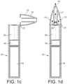
- the cartridge 20 contains an aerosol-forming substrate and is configured to be received in a cavity 18 within the device. Cartridge 20 should be replaceable by a user when the aerosol-forming substrate provided in the cartridge is depleted.
- Figure 1a shows the cartridge 20 just prior to insertion into the device, with the arrow 1 in Figure 1a indicating the direction of insertion of the cartridge.
- the aerosol-generating device 10 is portable and has a size comparable to a conventional cigar or cigarette.
- the device 10 comprises a main body 11 and a mouthpiece portion 12.
- the main body 11 contains a battery 14, such as a lithium iron phosphate battery, electric circuitry 16 and a cavity 18.
- the electric circuitry 16 comprises a programmable microprocessor.
- the mouthpiece portion 12 is connected to the main body 11 by a hinged connection 21 and can move between an open position as shown in Figure 1 and a closed position as shown in Figure 1d .
- the mouthpiece portion 12 is placed in the open position to allow for insertion and removal of cartridges 20 and is placed in the closed position when the system is to be used to generate aerosol.
- the mouthpiece portion comprises a plurality of air inlets 13 and an outlet 15.
- a user sucks or puffs on the outlet to draw air from the air inlets 13, through the mouthpiece portion to the outlet 15, and thereafter into the mouth or lungs of the user.
- Internal baffles 17 are provided to force the air flowing through the mouthpiece portion 12 past the cartridge.
- the cavity 18 has a circular cross-section and is sized to receive a housing 24 of the cartridge 20.
- Electrical connectors 19 are provided at the sides of the cavity 18 to provide an electrical connection between the control electronics 16 and battery 14 and corresponding electrical contacts on the cartridge 20.
- Figure 1b shows the system of Figure 1a with the cartridge inserted into the cavity 18, and the cover 26 being removed. In this position, the electrical connectors rest against the electrical contacts on the cartridge.
- Figure 1c shows the system of Figure 1b with the cover 26 fully removed and the mouthpiece portion 12 being moved to a closed position.
- Figure 1d shows the system of Figure 1c with the mouthpiece portion 12 in the closed position.
- the mouthpiece portion 12 is retained in the closed position by a clasp mechanism.
- the mouthpiece portion 12 in a closed position retains the cartridge in electrical contact with the electrical connectors 19 so that a good electrical connection is maintained in use, whatever the orientation of the system is.
- FIG. 2 is an exploded view of the cartridge 20.
- the cartridge 20 comprises a generally circular cylindrical housing 24 that has a size and shape selected to be received into the cavity 18.
- the housing contains capillary material 27, 28 that is soaked in a liquid aerosol-forming substrate.
- the aerosol-forming substrate comprises 39% by weight glycerine, 39% by weight propylene glycol, 20% by weight water and flavourings, and 2% by weight nicotine.
- a capillary material is a material that actively conveys liquid from one end to another, and may be made from any suitable material. In this example the capillary material is formed from polyester.
- the housing has an open end to which a heater assembly 30 is fixed.
- the heater assembly 30 comprises a substrate 34 having an aperture 35 formed in it, a pair of electrical contacts 32 fixed to the substrate and separated from each other by a gap 33, and a plurality of electrically conductive heater filaments 36 spanning the aperture and fixed to the electrical contacts on opposite sides of the aperture 35.
- the heater assembly 30 is covered by a removable cover 26.
- the cover comprises a liquid impermeable plastic sheet that is glued to the heater assembly but which can be easily peeled off.
- a tab is provided on the side of the cover to allow a user to grasp the cover when peeling it off.
- a disc of a first capillary material 27 is provided to contact the heater element 36, 32 in use.
- a larger body of a second capillary material 28 is provided on an opposite side of the first capillary material 27 to the heater assembly. Both the first capillary material and the second capillary material retain liquid aerosol-forming substrate.
- the first capillary material 27, which contacts the heater element, has a higher thermal decomposition temperature (at least 160°C or higher such as approximately 250°C) than the second capillary material 28.
- the first capillary material 27 effectively acts as a spacer separating the heater element 36, 32 from the second capillary material 28 so that the second capillary material is not exposed to temperatures above its thermal decomposition temperature.
- the thermal gradient across the first capillary material is such that the second capillary material is exposed to temperatures below its thermal decomposition temperature.
- the second capillary material 28 may be chosen to have superior wicking performance to the first capillary material 27, may retain more liquid per unit volume than the first capillary material and may be less expensive than the first capillary material.
- the first capillary material is a heat resistant material, such as a fiberglass or fiberglass containing material and the second capillary material is a polymer such as suitable capillary material.
- Exemplary suitable capillary materials include the capillary materials discussed herein and in alternative embodiments may include high density polyethylene (HDPE), or polyethylene terephthalate (PET).
- the capillary material 27, 28 is advantageously oriented in the housing 24 to convey liquid to the heater assembly 30.
- the heater filaments 36, 37, 38 may be in contact with the capillary material 27 and so aerosol-forming substrate can be conveyed directly to the mesh heater.
- Figure 3 is a detailed view of the filaments 36 of the heater assembly, showing a meniscus 40 of liquid aerosol-forming substrate between the heater filaments 36. It can be seen that aerosol-forming substrate contacts most of the surface of each filament so that most of the heat generated by the heater assembly passes directly into the aerosol-forming substrate.
- liquid aerosol-forming substrate contacts a large portion of the surface of the heater filaments 36.
- less liquid aerosol-forming substrate will be delivered to the heater filaments.
- less energy is taken up by the enthalpy of vaporization and more of the energy supplied to the heating filaments is directed to raising the temperature of the heating filaments.
- the rate of increase of temperature of the heater element for a given applied power will increase.
- the heater element may dry out because the aerosol-forming substrate in the cartridge is almost used up or because the user is taking very long or very frequent puffs and the liquid cannot be delivered to the heater filaments as fast as it is being vaporized.
- the heater assembly operates by resistive heating.
- Current is passed through the filaments 36 under the control of control electronics 16, to heat the filaments to within a desired temperature range.
- the mesh or array of filaments has a significantly higher electrical resistance than the electrical contacts 32 and electrical connectors 19 so that the high temperatures are localised to the filaments.
- the system is configured to generate heat by providing electrical current to the heater assembly in response to a user puff.
- the system may be configured to generate heat continuously while the device is in an "on" state.
- Different materials for the filaments may be suitable for different systems.
- Ni-Cr filaments are suitable as they have a relatively low specific heat capacity and are compatible with low current heating.
- stainless steel filaments having a high specific heat capacity may be more suitable.
- the system includes a puff sensor configured to detect when a user is drawing air through the mouthpiece portion.
- the puff sensor (not illustrated) is connected to the control electronics 16 and the control electronics 16 are configured to supply current to the heater assembly 30 only when it is determined that the user is puffing on the device.
- Any suitable air flow sensor may be used as a puff sensor, such as a microphone or pressure sensor.
- the electric circuitry 16 is configured to measure the electrical resistance of the heater filaments.
- the heater filaments in this example are formed from stainless steel, and so have a positive temperature coefficient of resistance. This means that as the temperature of the heater filaments rises so does their electrical resistance. It will be appreciated that in other embodiments the heater filaments may be formed from a material having a negative coefficient of resistance, for which, as the temperature of the heater filaments rises their electrical resistance decreases.
- FIG 4 is a schematic illustration of the change of resistance of the heater during a user puff.
- the x-axis is time after initial detection of a user puff and the resulting supply of power to the heater.
- the y-axis is electrical resistance of the heater assembly. It can be seen that the heater assembly has an initial resistance R 1 before any heating has occurred.
- R 1 is made up of a parasitic resistance Rp resulting from the electrical contacts 32 and electrical connectors 19 and the contact between them, and the resistance of the heater filaments R 0 .
- R 1 is made up of a parasitic resistance Rp resulting from the electrical contacts 32 and electrical connectors 19 and the contact between them, and the resistance of the heater filaments R 0 .
- the resistance of the heater assembly is R 2 .
- the parasitic resistance Rp is assumed to not change as the heater filaments heat up. This is because Rp is attributable to non-heated components, such as the electrical contacts 32 and electrical connectors 19.
- the value of Rp is assumed to be the same for all cartridges and a value is stored in the memory of the electric circuitry.
- the electrical circuitry can be configured to determine the change in resistance by determining the difference between measurements of the initial electrical resistance R 1 of the heater filaments before power is supplied to the heater elements, in other words before a puff, and measurements the electrical resistance R 2 of the heater filaments after a predetermined time period ⁇ t 1 from when power is supplied to the heater filaments.
- the electrical circuitry can be configured to determine whether the change in resistance is indicative of an unacceptably rapid increase in temperature by comparing the difference ⁇ R to a predetermined maximum threshold value ⁇ R max .
- R 2 and R 1 are both measured values and ⁇ R max is stored in memory. Ideally the value of R 1 is measured before any heating takes place, in other words before first activation of the heater. This initial measured value may be used for all subsequent puffs, in order to avoid any error resulting from residual heat from previous puffs. As such, the initial measured electrical resistance before any heating takes place will be referred to as R 1ref .
- R 1ref may be measured only once for each cartridge and a detection system used to determine when a new cartridge is inserted, or R 1 may be measured each time the system is switched on.
- the electrical circuitry is configured to periodically take updated measurements of R 1ref after predetermined time periods in which no power has been supplied to the heater filaments.
- the predetermined time period is typically 3 minutes, but may be any suitable time required for the heater filaments to cool from their operating temperature back to room temperature.
- the periodic updates to R 1ref may recalibrate the electrical circuitry to compensate for changes in ambient temperature and changes in the condition of the heater filaments.
- a cartridge having a heater formed from a material having a different temperature coefficient of resistance is used in the system, the electric circuitry can detect that and may be configured not to supply power to it.
- the heater filaments are formed from stainless steel.
- a cartridge having a heater formed from Ni-Cr would have a lower temperature coefficient of resistance, meaning that its resistance would rise more slowly with increasing temperature.
- a minimum resistance threshold value ⁇ R min may be stored in the memory of the electrical circuitry which corresponds to the lowest temperature rise in time period ⁇ t 1 expected for a stainless steel heater element.
- the electrical circuitry may be configured to determine an adverse condition corresponding to an unauthorized cartridge being present in the system if the change in resistance between R2 and R1ref is less than the minimum threshold value ⁇ R min .
- the system may be configured to compare the difference between R 2 and R 1ref with a stored high threshold and a stored low threshold in order to determine adverse conditions.
- R 1ref may also be compared with a threshold or thresholds to check that it is within an expected range. They may even be more than one high stored threshold and different actions taken depending on which high threshold is exceeded. For example, if the highest threshold is exceeded then the circuitry may prevent further supply of power until the heater and/or substrate is replaced. This may be indicative of a completely depleted substrate or a damages or incompatible heater.
- a lower threshold may be used to determine when the substrate is nearly depleted. If this lower threshold is exceeded, but the higher threshold is not exceeded, then the circuitry may simply provide an indication, such as an illuminated LED, showing that the substrate will soon need to be replaced.
- the difference between R 1ref and R 2 may be continually monitored to determine if the heater is cooling sufficiently between puffs. If the difference does not go below a cooling threshold between puffs because a user is puffing very frequently, the electric circuitry may prevent or limit the supply of power to the heater until the difference falls below the cooling threshold. Alternatively, a comparison may be made between a maximum value of the difference during a puff and a minimum value for the difference subsequent to the puff, to determine if sufficient cooling is occurring.
- the difference between R 1 and R 2 may be continually monitored and the time at which it reaches a threshold value compared with a time threshold. If the difference between R 1ref and R 2 reaches the threshold much faster or slower than expected, then it may be indicative of an adverse condition, such as an incompatible heater. The rate of change could also be determined and compared with a threshold. If the difference rises very quickly or very slowly then it may be indicative of an adverse condition. These techniques may allow for incompatible heaters to be detected very quickly.
- FIG. 5 is a schematic electric circuit diagram showing how the heating element resistance may be measured.
- the heater 501 is connected to a battery 503 which provides a voltage V 2.
- the heater resistance to be measured at a particular time is R heater .
- an additional resistor 505, with known resistance r is inserted connected to voltage V 1, intermediate between ground and voltage V 2.
- the additional resistor 505 whose resistance r is known, is used to determine the current I, again using (2) above.
- the current through the resistor 505 is I and the voltage across the resistor 505 is V1.
- I V 1 r
- the microprocessor 507 can measure V2 and V1, as the aerosol generating system is being used and, knowing the value of r, can determine the heater's resistance, R heater at different times.
- the electric circuitry can control the supply of power to the heater in several different ways following an adverse condition being detected. Alternatively, or in addition, the electric circuitry may simply provide an indication to the use that an adverse condition has been detected.
- the system may include an LED or display or may comprise a microphone, and these components may be used to issue an alert of an adverse condition to the user.
- Figure 6 illustrates a control process for a puff actuated system according to the present invention.
- Figure 6 shows four consecutive puffs, P 1 , P 2 , P 3 and P 4 .
- the first puff P 1 is a normal puff in which there is no abnormal condition.
- the three subsequent puffs P 2 , P 3 and P 4 are all abnormal puffs, which exceed the high threshold ⁇ R max .
- Each puff is detected at a time ti, at which point power is supplied to the heater filaments.
- the resistance of the heater filaments at time t 1 is shown as R 1 .
- the initial resistance R 1 of the heater filaments for the first puff P1 is equal to the initial reference resistance R 1ref , which was measured before heating began.
- Subsequent abnormal puffs P 2 , P 3 and P 4 show an initial resistance R 1 at time t 1 that is above the initial reference resistance R 1ref . This indicates that the heater filaments have not had sufficient time to cool back to room temperature between puffs.
- the resistance of the heater filaments is measured at time t 2 , after a predetermined time period ⁇ t 1 following the detection of the puff.
- Each puff ends at time t 3 , lasting for a total time period of ⁇ t puff .
- the electric circuitry stops the supply of power to the heater as soon as it is determined that the high threshold has been exceeded, until the end of the user puff. This is shown at time t h for the second, third and fourth puffs P 2 , P 3 and P 4 . This may be useful to prevent the heater becoming too hot even when the user is puffing excessively. As well as stopping the power, an indication could be provided that the threshold has been reached.
- the cartridges are removable from the devices.
- a user may remove a cartridge from a device when the cartridge is empty of liquid aerosol-forming substrate to dispose of or refill the cartridge.
- a user may also remove a cartridge that is partially empty and still contains liquid aerosol-forming substrate.
- a user may insert a used cartridge into the device. For example, a user may insert a refilled or partially empty cartridge into the device.
- the heater may not have had sufficient time to cool down to room temperature after the previous use. If the electrical circuitry of the device measures the initial resistance R 1ref of the heater filaments when the heater filaments are still hot, this may skew the determination of adverse conditions by the electric circuitry, and may result in the heater filaments being heated to an undesirable temperature.
- the electric circuitry may be configured to determine whether the temperature of a heater of a recently inserted cartridge is stable. In other words, the electric circuitry may be configured to determine if the heater of a recently inserted cartridge is at a cool temperature, typically room temperature. This may substantially prevent or inhibit the electric circuitry from measuring the initial resistance R 1ref of the heater filaments when the heater filaments are hot.
- the electric circuitry is configured to determine when a cartridge is received in the device. As such, the electric circuitry is configured to determine when a cartridge is removed from the device and when a cartridge is inserted into the device.
- the electric circuitry may be configured to measure a preliminary resistance R p1 of the heater filaments.
- the electric circuitry may also be configured to measure a subsequent preliminary resistance R p2 of the heater filaments after a predetermined time period ⁇ T 2 , typically between about 1 s and about 2 s.
- the electrical circuitry may then be configured to determine the difference ⁇ R p between the measured preliminary resistances R p1 , R p2 . If the temperature of the heater filaments is stable, the magnitude difference
- the electric circuitry may be configured to compare the difference ⁇ R p to a minimum threshold value ⁇ R pmin and to determine whether the temperature of the heater filaments is stable based on the comparison.
- the electric circuitry may be configured to determine that the temperature of the heater filaments is not stable if the difference
- the electric circuitry may be configured to perform the following comparison: If R p 2 ⁇ R p 1 > ⁇ R pmin then the temperature of the heater is not stable where R p2 and R p1 are both measured values and ⁇ R pmin is stored in memory.
- the electric circuitry may be configured to compare the magnitude of the difference
- the electric circuitry may be configured to determine that the temperature of the heater filaments is not stable if the magnitude of the difference
- the electric circuitry may prevent power from being supplied to the heater filaments and may not measure and store an initial resistance R 1ref .
- the electric circuitry may be configured to periodically or continuously measure the subsequent preliminary resistance R p2 , determine the difference ⁇ R p to the initial preliminary resistance R p1 and compare the difference ⁇ R p to the minimum threshold ⁇ R pmin until the difference it is within the expected level for heater filaments at a stable temperature, which is as close to zero as possible.
- the electric circuitry may be configured to determine the initial reference resistance R 1ref and perform the usual processes described above.
- the electric circuitry may be configured to periodically measure a single preliminary resistance R p1 after insertion of a new cartridge and determine the difference ⁇ R p between the preliminary resistance R p1 and the previous reference resistance R 1ref that was measured and stored for the previous cartridge, before the previous cartridge was removed.
- FIG. 7 illustrates an alternative system, which also uses a liquid substrate and a capillary material, in accordance with the invention.
- the electrically heated aerosol-generating system 100 of Figure 7 comprises a housing 101 having a mouthpiece end 103 and a body end 105.
- an electric power supply in the form of battery 107 and electric circuitry 109.
- a puff detection system 111 is also provided in cooperation with the electric circuitry 109.
- capillary wick 117 extends into cartridge 113 and the other end of capillary wick 117 is surrounded by the heater 119.
- the heater is connected to the electric circuitry via connections 121, which may pass along the outside of cartridge 113 (not shown in Figure 7 ).
- the housing 101 also includes an air inlet 123, an air outlet 125 at the mouthpiece end, and an aerosol-forming chamber 127.
- Liquid 115 is conveyed by capillary action from the cartridge 113 from the end of the wick 117 which extends into the cartridge to the other end of the wick which is surrounded by heater 119.
- the puff detection system 111 senses the puff and activates the heater 119.
- the battery 107 supplies electrical energy to the heater 119 to heat the end of the wick 117 surrounded by the heater.
- the liquid in that end of the wick 117 is vaporized by the heater 119 to create a supersaturated vapour.
- the liquid being vaporized is replaced by further liquid moving along the wick 117 by capillary action.
- the supersaturated vapour created is mixed with and carried in the air flow from the air inlet 123.
- the vapour condenses to form an inhalable aerosol, which is carried towards the outlet 125 and into the mouth of the user.
- the electric circuitry 109 and puff detection system 111 are programmable as in the embodiment of Figures 1a to 1d .
- the capillary wick can be made from a variety of porous or capillary materials and preferably has a known, pre-defined capillarity. Examples include ceramic- or graphite-based materials in the form of fibres or sintered powders. Wicks of different porosities can be used to accommodate different liquid physical properties such as density, viscosity, surface tension and vapour pressure. The wick must be suitable so that the required amount of liquid can be delivered to the heater when the liquid storage portion has sufficient liquid.
- the heater comprises at least one heating wire or filament extending around the capillary wick.
- the capillary material forming the wick may dry out in the vicinity of the heater wire if the liquid in the cartridge is used up or if the user takes very long, deep puffs.
- the change in resistance of the heater wire during the first portion of each puff can be used to determine if there is an adverse condition, such as a dry wick.
- a system of the type illustrated in Figure 7 may have considerable variation in heater resistance, even between cartridges of the same type, because of variations in the length of heater wire wrapped around the wick.
- the invention is particularly advantageous as it does not require the electric circuitry to store a maximum heater resistance value as a threshold; instead it is a resistance increase relative to an initial measured resistance that is used.
- Figure 8 illustrates yet another aerosol-generating system which can embody the invention.
- the embodiment of Figure 8 is electrically heated tobacco device in which a tobacco based solid substrate is heated, but not combusted, to produce an aerosol for inhalation.
- the components of the aerosol-generating device 700 are shown in a simplified manner and are not drawn to scale. Elements that are not relevant for the understanding of this embodiment have been omitted to simplify Figure 8 .
- the electrically heated aerosol-generating device 200 comprises a housing 203 and an aerosol-forming substrate 210, for example a cigarette.
- the aerosol-forming substrate 210 is pushed inside a cavity 205 formed by the housing 203 to come into thermal proximity with the heater 201.
- the aerosol-forming substrate 210 releases a range of volatile compounds at different temperatures. By controlling the operation temperature of the electrically heated aerosol-generating device 200 to be below the release temperature of some of the volatile compounds, the release or formation of smoke constituents can be avoided.
- Electric circuitry 209 is connected to the heater 201 and the electrical power supply 207.
- the electric circuitry 209 controls the power supplied to the heater 201 in order to regulate its temperature.
- An aerosol-forming substrate detector 213 may detect the presence and identity of an aerosol-forming substrate 210 in thermal proximity with the heater 201 and signals the presence of an aerosol-forming substrate 210 to the electric circuitry 209. The provision of a substrate detector is optional.
- An airflow sensor 211 is provided within the housing and connected to the electric circuitry 209, to detect the airflow rate through the device.
- the heater 201 is an electrically resistive track or tracks deposited on a ceramic substrate.
- the ceramic substrate is in the form of a blade and is inserted into the aerosol-forming substrate 210 in use.
- the heater forms part of the device and may be used for heating many different substrates. However, the heater may be a replaceable component, and replacement heaters may have different electrical resistance.
- a system of the type described in Figure 8 may be a continuously heated system in which the temperature of the heater is maintained at a target temperature while the system in on, or it may be a puff actuated system in the temperature of the heater is raised by supplying more power during periods when a puff is detected.
- the operation is very similar to that described with reference to the preceding embodiments. If the substrate is dry in the vicinity of the heater, the heater resistance will rise more quickly for a given applied power than if the substrate still contains aerosol-formers that can be vaporized at relatively low temperature.
- the system of Figure 8 includes a warning LED 215 in the electric circuitry 209 which is illuminated when an adverse condition is detected.
- FIG. 9 is flow chart illustrating a method for detecting an unauthorised, damaged or incompatible heater.
- a first step 300 the insertion of a cartridge, including the heater, into the device is detected.
- the electrical resistance of the heater R 1ref is measured in step 300. This occurs a predetermined time period after power is supplied to the heater, such as 100ms.
- step 320 the measured resistance R 1 is compared with a range of expected or acceptable resistances. The range of acceptable resistances takes account of manufacturing tolerances and variations between genuine heaters and substrates. If R 1 is outside of the expected range then the process proceeds to step 330, in which an indication, such as an audible alarm, is provided and power is prevented from being supplied to the heater as it is considered to be incompatible with the device. The process then returns to step 300, waiting for detection of the insertion of a new cartridge.
- an initial rate of change of resistance may be measured within a predetermined time period, say 100ms, after power is supplied to the heater. This may be done by taking a plurality of resistance measurements at different times during the predetermined time period and then calculating an initial rate of change of resistance from the plurality of resistance measurements and the times at which those measurements were taken.
- a particular design of heater can be expected to have an initial resistance within a range of acceptable values
- a particular design of heater can be expected to have an initial rate of change of resistance for a given applied power within an acceptable range of rate of change of resistance values.
- the calculated initial rate of change of resistance can be compared to an acceptable range of rate of change of resistance values and if the calculated rate of change of resistance is outside of the acceptable range, then the process proceeds to step 330.
- step 320 If in step 320 it is determined that R 1ref is in the range of expected resistance, then the process proceeds to step 340.
- step 340 power is applied to the heater for a time period ⁇ t 1 , after which the difference ⁇ R is calculated.
- ⁇ t 1 is chosen to be a short time period, before significant generation of aerosol.
- step 350 the value of ⁇ R is compared with a range of expected or acceptable values. The range of expected values again takes account of variations in the manufacture of the heater and substrate assembly. If the value of ⁇ R is outside of the expected range, the heater is considered incompatible and the process goes to step 330, as previously described, and then returns to step 300. If the value of ⁇ R is inside the expected range, then the process proceeds to step 360, in which power is supplied to the heater to allow for the generation of aerosol on demand by the user.
- the invention may be implemented as a computer program product for execution on programmable controllers within existing aerosol-generating systems.
- the computer program product may be provided as a downloadable piece of software or on a computer readable medium such as a compact disc.
- an electrically operated aerosol-generating system a heater assembly, an electrically operated aerosol-generating device, electric circuitry, a method of controlling the supply of power to an electric heater or a computer program product as described in the following set of numbered clauses:
Applications Claiming Priority (3)
| Application Number | Priority Date | Filing Date | Title |
|---|---|---|---|
| EP16180977 | 2016-07-25 | ||
| EP17734374.6A EP3487326B1 (fr) | 2016-07-25 | 2017-07-05 | Gestion de chauffage |
| PCT/EP2017/066838 WO2018019533A1 (fr) | 2016-07-25 | 2017-07-05 | Gestion d'un dispositif de chauffage |
Related Parent Applications (1)
| Application Number | Title | Priority Date | Filing Date |
|---|---|---|---|
| EP17734374.6A Division EP3487326B1 (fr) | 2016-07-25 | 2017-07-05 | Gestion de chauffage |
Publications (2)
| Publication Number | Publication Date |
|---|---|
| EP3954236A2 true EP3954236A2 (fr) | 2022-02-16 |
| EP3954236A3 EP3954236A3 (fr) | 2022-04-13 |
Family
ID=56550110
Family Applications (2)
| Application Number | Title | Priority Date | Filing Date |
|---|---|---|---|
| EP17734374.6A Active EP3487326B1 (fr) | 2016-07-25 | 2017-07-05 | Gestion de chauffage |
| EP21195392.2A Pending EP3954236A3 (fr) | 2016-07-25 | 2017-07-05 | Gestion de chauffage |
Family Applications Before (1)
| Application Number | Title | Priority Date | Filing Date |
|---|---|---|---|
| EP17734374.6A Active EP3487326B1 (fr) | 2016-07-25 | 2017-07-05 | Gestion de chauffage |
Country Status (19)
| Country | Link |
|---|---|
| US (4) | US10299514B2 (fr) |
| EP (2) | EP3487326B1 (fr) |
| JP (3) | JP7256738B2 (fr) |
| KR (2) | KR102595270B1 (fr) |
| CN (3) | CN109475191B (fr) |
| AR (1) | AR109144A1 (fr) |
| AU (1) | AU2017304338A1 (fr) |
| CA (1) | CA3028527A1 (fr) |
| IL (1) | IL263364B (fr) |
| MX (1) | MX2019000910A (fr) |
| MY (1) | MY191523A (fr) |
| PH (1) | PH12018502514A1 (fr) |
| PL (1) | PL3487326T3 (fr) |
| RU (2) | RU2021114730A (fr) |
| SG (1) | SG11201811639WA (fr) |
| TW (1) | TW201803469A (fr) |
| UA (1) | UA126796C2 (fr) |
| WO (1) | WO2018019533A1 (fr) |
| ZA (1) | ZA201807966B (fr) |
Cited By (1)
| Publication number | Priority date | Publication date | Assignee | Title |
|---|---|---|---|---|
| WO2024064676A1 (fr) * | 2022-09-19 | 2024-03-28 | Altria Client Services Llc | Système de surveillance de capsule pour dispositif de génération d'aérosol |
Families Citing this family (74)
| Publication number | Priority date | Publication date | Assignee | Title |
|---|---|---|---|---|
| CN107404945B (zh) * | 2015-04-06 | 2020-08-04 | 日本烟草产业株式会社 | 香味吸取器及内侧保持部件 |
| US10165799B2 (en) * | 2015-11-17 | 2019-01-01 | Altria Client Services Llc | Aerosol-generating system with self-activated electric heater |
| US10264821B2 (en) | 2016-03-21 | 2019-04-23 | Altria Client Services Llc | Electronic vaping device |
| TW201800020A (zh) * | 2016-06-29 | 2018-01-01 | 菲利浦莫里斯製品股份有限公司 | 具有可充電電源供應器之電操作式氣溶膠產生系統 |
| RU2021114730A (ru) * | 2016-07-25 | 2021-06-01 | Филип Моррис Продактс С.А. | Управление нагревателем |
| TW201843553A (zh) * | 2017-05-02 | 2018-12-16 | 瑞士商菲利浦莫里斯製品股份有限公司 | 用於氣溶膠產生裝置之加熱器總成 |
| EP3942951B1 (fr) * | 2017-08-09 | 2023-10-04 | Philip Morris Products S.A. | Dispositif de génération d'aérosol ayant un compartiment de chauffage insérable de manière amovible |
| DE102017123866A1 (de) * | 2017-10-13 | 2019-04-18 | Hauni Maschinenbau Gmbh | Inhalator, insbesondere elektronisches Zigarettenprodukt |
| IL263217B (en) * | 2017-11-24 | 2022-06-01 | Juul Labs Inc | Emission sensing and power circuit for vaporizers |
| JP7267279B2 (ja) * | 2017-11-30 | 2023-05-01 | フィリップ・モーリス・プロダクツ・ソシエテ・アノニム | エアロゾル発生装置およびエアロゾル発生装置のヒーターを制御するための方法 |
| EP3727055B1 (fr) * | 2017-12-22 | 2021-12-15 | Philip Morris Products S.A. | Dispositif de génération d'aérosol doté d'un compartiment de chauffage à nettoyage facile |
| WO2019148049A1 (fr) * | 2018-01-26 | 2019-08-01 | Evolv, Llc | Dispositif de simulation de cigarette électronique avec enregistrement de résistance et relecture |
| EP3763230A4 (fr) * | 2018-03-05 | 2021-10-27 | Japan Tobacco Inc. | Article à fumer de type à chauffage sans combustion |
| WO2019200559A1 (fr) * | 2018-04-18 | 2019-10-24 | 深圳麦克韦尔股份有限公司 | Cigarette électronique, noyau d'atomisation, atomiseur et procédé de commande de cigarette électronique |
| US20210235770A1 (en) * | 2018-04-23 | 2021-08-05 | Philip Morris Products S.A. | An aerosol-generating device having temperature-based control |
| PL3801084T3 (pl) | 2018-05-30 | 2022-10-24 | Philip Morris Products S.A. | Sposoby wykrywania stanów ogrzewacza w układzie wytwarzania aerozolu |
| BR112020022094A2 (pt) | 2018-05-30 | 2021-02-02 | Philip Morris Products S.A. | detecção de condições adversas de aquecedor em um sistema gerador de aerossol aquecido eletricamente |
| CN112312785A (zh) | 2018-06-07 | 2021-02-02 | 尤尔实验室有限公司 | 用于蒸发器装置的料盒 |
| CN112533498A (zh) * | 2018-06-14 | 2021-03-19 | 日本烟草产业株式会社 | 电源单元、香味生成装置、方法以及程序 |
| EA039744B1 (ru) * | 2018-06-20 | 2022-03-05 | ДжейТи ИНТЕРНЕШНЛ СА | Устройство, генерирующее пар |
| WO2019244324A1 (fr) | 2018-06-22 | 2019-12-26 | 日本たばこ産業株式会社 | Dispositif de génération d'aérosol, et procédé et programme pour le faire fonctionner |
| US10888125B2 (en) | 2018-06-27 | 2021-01-12 | Juul Labs, Inc. | Vaporizer device with subassemblies |
| EP3826493B1 (fr) * | 2018-07-25 | 2022-06-29 | Philip Morris Products S.A. | Procédé de régulation du chauffage dans un système de génération d'aérosol |
| CN112312782A (zh) * | 2018-07-26 | 2021-02-02 | 菲利普莫里斯生产公司 | 用于生成气溶胶的系统 |
| US20200352243A1 (en) * | 2018-07-27 | 2020-11-12 | Flytlab Llc | Portable vaporizer |
| EP3831227A4 (fr) * | 2018-07-30 | 2021-08-04 | Japan Tobacco Inc. | Dispositif et procédé de génération d'aérosol et programme d'actionnement associé |
| CN109090710B (zh) * | 2018-09-20 | 2021-01-05 | 深圳瀚星翔科技有限公司 | 一种雾化器阻值检测电路 |
| CN109077361A (zh) * | 2018-09-21 | 2018-12-25 | 李东 | 一种发热组件及电子烟 |
| US20210392956A1 (en) * | 2018-09-28 | 2021-12-23 | Philip Morris Products S. A. | Aerosol-generating system providing preferential evaporation of nicotine |
| JP2022504970A (ja) * | 2018-10-22 | 2022-01-13 | フィリップ・モーリス・プロダクツ・ソシエテ・アノニム | 検出器を備えたエアロゾル発生装置用のケース |
| WO2020092245A1 (fr) * | 2018-10-29 | 2020-05-07 | Zorday IP, LLC | Cigarette électronique compatible avec un réseau |
| EP3876764A1 (fr) | 2018-11-05 | 2021-09-15 | Juul Labs, Inc. | Cartouches pour dispositifs de vaporisation |
| EP3876760A1 (fr) | 2018-11-08 | 2021-09-15 | Juul Labs, Inc. | Cartouches pour dispositifs de vaporisateur |
| KR102199794B1 (ko) * | 2018-11-16 | 2021-01-07 | 주식회사 케이티앤지 | 연속사용이 가능한 에어로졸 생성장치의 히터의 전력을 제어하는 방법 및 그 에어로졸 생성장치 |
| EP3864983B8 (fr) * | 2018-11-30 | 2024-02-21 | Kennede Electronics Mfg.Co., Ltd. | Procédé de commande de cigarette électronique et cigarette électronique |
| CN109619682A (zh) * | 2018-12-11 | 2019-04-16 | 深圳市余看智能科技有限公司 | 气溶胶发生材料加热方法、加热组件及气溶胶发生装置 |
| JP6522847B1 (ja) * | 2018-12-19 | 2019-05-29 | 日本たばこ産業株式会社 | エアロゾル吸引器、これ用の制御装置、これの制御方法並びにこれ用の制御装置の動作方法及びプログラム |
| JP6553799B1 (ja) | 2018-12-19 | 2019-07-31 | 日本たばこ産業株式会社 | エアロゾル吸引器、これ用の制御装置、これの制御方法並びにこれ用の制御装置の動作方法及びプログラム |
| WO2020127501A1 (fr) * | 2018-12-20 | 2020-06-25 | Jt International Sa | Dispositif de génération de vapeur |
| JP2022515905A (ja) * | 2018-12-31 | 2022-02-22 | フィリップ・モーリス・プロダクツ・ソシエテ・アノニム | 電源供給のためのホルダーを有するエアロゾル発生装置用のケース |
| US11051657B2 (en) * | 2019-02-26 | 2021-07-06 | TRI Innovations LLC | Electronic grinder |
| US11191296B2 (en) * | 2019-02-26 | 2021-12-07 | TRI Innovations, LLC | Smart grinder |
| GB201903137D0 (en) * | 2019-03-08 | 2019-04-24 | Nicoventures Trading Ltd | Vapour provision system and corresponding method |
| GB201903144D0 (en) * | 2019-03-08 | 2019-04-24 | Nicoventures Trading Ltd | Vapour provision system and corresponding method |
| EP3711542A1 (fr) * | 2019-03-22 | 2020-09-23 | Nerudia Limited | Système de substitution au tabac à fumer |
| GB201905250D0 (en) * | 2019-04-12 | 2019-05-29 | Nicoventures Trading Ltd | Vapour provision system and corresponding method |
| KR102278590B1 (ko) * | 2019-04-18 | 2021-07-16 | 주식회사 케이티앤지 | 에어로졸 생성 장치 및 그의 동작 방법 |
| KR102253052B1 (ko) * | 2019-05-16 | 2021-05-17 | 주식회사 케이티앤지 | 에어로졸 생성 장치 및 그의 동작 방법 |
| WO2021072755A1 (fr) * | 2019-10-18 | 2021-04-22 | 深圳麦克韦尔科技有限公司 | Procédé de commande de chauffage d'ensemble d'atomisation, dispositif informatique et support de stockage |
| JP6667708B1 (ja) * | 2019-10-24 | 2020-03-18 | 日本たばこ産業株式会社 | エアロゾル吸引器の電源ユニット |
| US11911559B2 (en) | 2019-12-15 | 2024-02-27 | Shaheen Innovations Holding Limited | Ultrasonic mist inhaler |
| US20230017816A1 (en) * | 2020-01-06 | 2023-01-19 | Kt&G Corporation | Aerosol generating device |
| KR20210088386A (ko) * | 2020-01-06 | 2021-07-14 | 주식회사 케이티앤지 | 에어로졸 생성 장치 |
| CN113367389B (zh) * | 2020-02-25 | 2022-09-30 | 常州市派腾电子技术服务有限公司 | 烟液供给方法、装置及气溶胶发生装置 |
| JP6855611B1 (ja) * | 2020-03-05 | 2021-04-07 | 日本たばこ産業株式会社 | 吸引器用コントローラ |
| JP6841950B1 (ja) * | 2020-03-05 | 2021-03-10 | 日本たばこ産業株式会社 | 吸引器用コントローラ |
| JP2023517950A (ja) * | 2020-03-11 | 2023-04-27 | ジェイティー インターナショナル エス.エイ. | エアロゾル発生デバイス、方法、及びそのための制御回路 |
| KR102427856B1 (ko) * | 2020-04-13 | 2022-08-01 | 주식회사 케이티앤지 | 에어로졸 생성 장치 및 이를 제어하는 방법 |
| GB202006778D0 (en) * | 2020-05-07 | 2020-06-24 | Nicoventures Trading Ltd | Non-combustible aerosol provision system |
| US11789476B2 (en) | 2021-01-18 | 2023-10-17 | Altria Client Services Llc | Heat-not-burn (HNB) aerosol-generating devices including intra-draw heater control, and methods of controlling a heater |
| US11910826B2 (en) | 2021-01-18 | 2024-02-27 | Altria Client Services Llc | Heat-not-burn (HNB) aerosol-generating devices and capsules |
| CA3210847A1 (fr) * | 2021-03-03 | 2022-09-09 | Michel BESSANT | Dispositif de production d'aerosol avec detection de bouffee |
| GB202103375D0 (en) * | 2021-03-11 | 2021-04-28 | Nicoventures Trading Ltd | Aerosol provision system |
| KR102621761B1 (ko) * | 2021-04-01 | 2024-01-05 | 주식회사 케이티앤지 | 에어로졸 생성 물품이 과습 상태인지 여부를 판단하는 에어로졸 생성 장치 |
| JPWO2022239065A1 (fr) * | 2021-05-10 | 2022-11-17 | ||
| KR20220170684A (ko) * | 2021-06-23 | 2022-12-30 | 주식회사 케이티앤지 | 에어로졸 생성 장치 및 그의 동작 방법 |
| WO2023020966A1 (fr) * | 2021-08-17 | 2023-02-23 | Jt International Sa | Dispositif de génération d'aérosol |
| CN114018612B (zh) * | 2021-09-28 | 2024-02-23 | 彩虹显示器件股份有限公司 | 一种基板玻璃通道辅助加热器寿命预警方法及系统 |
| WO2023068638A1 (fr) * | 2021-10-19 | 2023-04-27 | Kt&G Corporation | Dispositif de génération d'aérosol et son procédé de fonctionnement |
| WO2023068639A1 (fr) * | 2021-10-19 | 2023-04-27 | Kt&G Corporation | Dispositif de génération d'aérosol et son procédé de fonctionnement |
| WO2023084196A1 (fr) * | 2021-11-10 | 2023-05-19 | Nicoventures Trading Limited | Dispositif de fourniture d'aérosol doté d'un capteur d'humidité |
| CN114253317B (zh) * | 2021-12-22 | 2023-07-04 | 深圳市基克纳科技有限公司 | 发热体的加热温度校准方法、装置及可读存储介质 |
| WO2024038530A1 (fr) * | 2022-08-17 | 2024-02-22 | 日本たばこ産業株式会社 | Dispositif d'inhalation, procédé de commande et programme |
| WO2024078610A1 (fr) * | 2022-10-15 | 2024-04-18 | 深圳市合元科技有限公司 | Ensemble de chauffage et dispositif de génération d'aérosol |
Citations (1)
| Publication number | Priority date | Publication date | Assignee | Title |
|---|---|---|---|---|
| WO2012085203A1 (fr) | 2010-12-24 | 2012-06-28 | Philip Morris Products Sa | Système générateur d'aérosol comportant des moyens permettant de déterminer l'épuisement d'un substrat liquide |
Family Cites Families (29)
| Publication number | Priority date | Publication date | Assignee | Title |
|---|---|---|---|---|
| US440997A (en) * | 1890-11-18 | Railroad-sleeper | ||
| JPH03287117A (ja) * | 1990-03-31 | 1991-12-17 | Aisin Seiki Co Ltd | コンタクトレンズ洗浄装置 |
| RU2191558C2 (ru) * | 1998-09-17 | 2002-10-27 | Педдер Валерий Викторович | Способ лечения облысения и устройство для его осуществления |
| US6234167B1 (en) * | 1998-10-14 | 2001-05-22 | Chrysalis Technologies, Incorporated | Aerosol generator and methods of making and using an aerosol generator |
| JP2003148698A (ja) * | 2001-11-16 | 2003-05-21 | Jeol Ltd | 温度制御装置 |
| US7177535B2 (en) | 2003-07-01 | 2007-02-13 | Philip Morris Usa Inc. | Apparatus for generating power and hybrid fuel vaporization system |
| US7167776B2 (en) * | 2004-09-02 | 2007-01-23 | Philip Morris Usa Inc. | Method and system for controlling a vapor generator |
| CA2595831C (fr) | 2005-02-02 | 2013-08-06 | Oglesby & Butler Research & Development Limited | Dispositif pour vaporiser de la matiere vaporisable |
| JP5515462B2 (ja) * | 2009-07-08 | 2014-06-11 | パナソニック株式会社 | シートヒータ制御装置 |
| EP2563172B2 (fr) | 2010-04-30 | 2022-05-04 | Fontem Holdings 4 B.V. | Dispositif électronique à fumer |
| EP2468118A1 (fr) * | 2010-12-24 | 2012-06-27 | Philip Morris Products S.A. | Système de génération d'aérosol afin de désactiver un consommable |
| AU2012360820B2 (en) | 2011-12-30 | 2017-07-13 | Philip Morris Products S.A. | Aerosol generating system with consumption monitoring and feedback |
| EP2609820A1 (fr) * | 2011-12-30 | 2013-07-03 | Philip Morris Products S.A. | Détection d'un substrat formant un aérosol dans un dispositif de génération d'aérosol |
| US9814262B2 (en) * | 2012-07-11 | 2017-11-14 | Sis Resources, Ltd. | Hot-wire control for an electronic cigarette |
| FI125544B (en) * | 2013-08-14 | 2015-11-30 | Pixan Oy | Apparatus and method for controlling an electric vaporizer |
| US9549573B2 (en) * | 2013-12-23 | 2017-01-24 | Pax Labs, Inc. | Vaporization device systems and methods |
| EP3142506B1 (fr) * | 2014-05-13 | 2018-12-19 | Fontem Holdings 4 B.V. | Dispositif électronique pour fumeur et applications d'échange de données |
| US11350669B2 (en) | 2014-08-22 | 2022-06-07 | Njoy, Llc | Heating control for vaporizing device |
| WO2016029225A1 (fr) * | 2014-08-22 | 2016-02-25 | Fontem Holdings 2 B.V. | Procédé, système et dispositif de commande d'un élément chauffant |
| GB2529629B (en) * | 2014-08-26 | 2021-05-12 | Nicoventures Trading Ltd | Electronic aerosol provision system |
| US10226076B2 (en) * | 2014-11-17 | 2019-03-12 | Mcneil Ab | Disposable cartridge for use in an electronic nicotine delivery system |
| CN104720119A (zh) | 2015-02-06 | 2015-06-24 | 董金明 | 自动恒温电子烟及其控制方法 |
| MY187082A (en) | 2015-03-26 | 2021-08-30 | Philip Morris Products Sa | Heater management |
| US10588350B2 (en) * | 2015-05-04 | 2020-03-17 | Fontem Holdings 1 B.V. | Liquid guiding structure, coil-less heating element and power management unit for electronic cigarettes |
| US10362803B2 (en) | 2015-06-10 | 2019-07-30 | Evolv, Llc | Electronic vaporizer having reduced particle size |
| US10524505B2 (en) | 2015-08-06 | 2020-01-07 | Altria Client Services Llc. | Method for measuring a vapor precursor level in a cartomizer of an electronic vaping device and/or an electronic vaping device configured to perform the method |
| CN205214209U (zh) * | 2015-10-21 | 2016-05-11 | 惠州市吉瑞科技有限公司深圳分公司 | 一种电子烟 |
| US10091488B2 (en) * | 2016-07-07 | 2018-10-02 | Visera Technologies Company Limited | 3D image sensor and 3D image-capturing device |
| RU2021114730A (ru) * | 2016-07-25 | 2021-06-01 | Филип Моррис Продактс С.А. | Управление нагревателем |
-
2017
- 2017-07-05 RU RU2021114730A patent/RU2021114730A/ru unknown
- 2017-07-05 EP EP17734374.6A patent/EP3487326B1/fr active Active
- 2017-07-05 MX MX2019000910A patent/MX2019000910A/es unknown
- 2017-07-05 EP EP21195392.2A patent/EP3954236A3/fr active Pending
- 2017-07-05 CA CA3028527A patent/CA3028527A1/fr not_active Abandoned
- 2017-07-05 CN CN201780043490.5A patent/CN109475191B/zh active Active
- 2017-07-05 KR KR1020197002068A patent/KR102595270B1/ko active IP Right Grant
- 2017-07-05 JP JP2019503711A patent/JP7256738B2/ja active Active
- 2017-07-05 SG SG11201811639WA patent/SG11201811639WA/en unknown
- 2017-07-05 AU AU2017304338A patent/AU2017304338A1/en not_active Abandoned
- 2017-07-05 KR KR1020237035667A patent/KR20230151552A/ko not_active Application Discontinuation
- 2017-07-05 PL PL17734374T patent/PL3487326T3/pl unknown
- 2017-07-05 WO PCT/EP2017/066838 patent/WO2018019533A1/fr unknown
- 2017-07-05 UA UAA201811732A patent/UA126796C2/uk unknown
- 2017-07-05 RU RU2019102942A patent/RU2749372C2/ru active
- 2017-07-05 CN CN202210767602.4A patent/CN115211604A/zh active Pending
- 2017-07-05 MY MYPI2018002196A patent/MY191523A/en unknown
- 2017-07-05 CN CN202210770461.1A patent/CN115119978A/zh active Pending
- 2017-07-13 TW TW106123488A patent/TW201803469A/zh unknown
- 2017-07-24 AR ARP170102075A patent/AR109144A1/es unknown
- 2017-07-25 US US15/658,713 patent/US10299514B2/en active Active
-
2018
- 2018-11-26 ZA ZA2018/07966A patent/ZA201807966B/en unknown
- 2018-11-28 PH PH12018502514A patent/PH12018502514A1/en unknown
- 2018-11-29 IL IL263364A patent/IL263364B/en unknown
-
2019
- 2019-05-24 US US16/421,936 patent/US10555560B2/en active Active
-
2020
- 2020-01-02 US US16/732,735 patent/US10905169B2/en active Active
-
2021
- 2021-01-06 US US17/142,565 patent/US11950327B2/en active Active
-
2022
- 2022-03-29 JP JP2022052802A patent/JP2022079558A/ja active Pending
-
2023
- 2023-09-08 JP JP2023146335A patent/JP2023158190A/ja active Pending
Patent Citations (1)
| Publication number | Priority date | Publication date | Assignee | Title |
|---|---|---|---|---|
| WO2012085203A1 (fr) | 2010-12-24 | 2012-06-28 | Philip Morris Products Sa | Système générateur d'aérosol comportant des moyens permettant de déterminer l'épuisement d'un substrat liquide |
Cited By (1)
| Publication number | Priority date | Publication date | Assignee | Title |
|---|---|---|---|---|
| WO2024064676A1 (fr) * | 2022-09-19 | 2024-03-28 | Altria Client Services Llc | Système de surveillance de capsule pour dispositif de génération d'aérosol |
Also Published As
Similar Documents
| Publication | Publication Date | Title |
|---|---|---|
| US20210212170A1 (en) | Heater management | |
| EP3487326B1 (fr) | Gestion de chauffage | |
| US20210204609A1 (en) | Detection of adverse heater conditions in an electrically heated aerosol generating system | |
| BR112018077199B1 (pt) | Sistema gerador de aerossol operado eletricamente, conjunto aquecedor, dispositivo gerador de aerossol operado eletricamente para um sistema gerador de aerossol operado eletricamente, circuitos elétricos para um sistema gerador de aerossol operado eletricamente, e método para controle do fornecimento de energia a um aquecedor elétrico em um sistema gerador de aerossol operado eletricamente |
Legal Events
| Date | Code | Title | Description |
|---|---|---|---|
| PUAI | Public reference made under article 153(3) epc to a published international application that has entered the european phase |
Free format text: ORIGINAL CODE: 0009012 |
|
| STAA | Information on the status of an ep patent application or granted ep patent |
Free format text: STATUS: THE APPLICATION HAS BEEN PUBLISHED |
|
| AC | Divisional application: reference to earlier application |
Ref document number: 3487326 Country of ref document: EP Kind code of ref document: P |
|
| AK | Designated contracting states |
Kind code of ref document: A2 Designated state(s): AL AT BE BG CH CY CZ DE DK EE ES FI FR GB GR HR HU IE IS IT LI LT LU LV MC MK MT NL NO PL PT RO RS SE SI SK SM TR |
|
| PUAL | Search report despatched |
Free format text: ORIGINAL CODE: 0009013 |
|
| AK | Designated contracting states |
Kind code of ref document: A3 Designated state(s): AL AT BE BG CH CY CZ DE DK EE ES FI FR GB GR HR HU IE IS IT LI LT LU LV MC MK MT NL NO PL PT RO RS SE SI SK SM TR |
|
| RIC1 | Information provided on ipc code assigned before grant |
Ipc: H05B 1/02 20060101ALI20220309BHEP Ipc: A24F 40/57 20200101ALI20220309BHEP Ipc: A24F 40/53 20200101AFI20220309BHEP |
|
| STAA | Information on the status of an ep patent application or granted ep patent |
Free format text: STATUS: REQUEST FOR EXAMINATION WAS MADE |
|
| 17P | Request for examination filed |
Effective date: 20221013 |
|
| RBV | Designated contracting states (corrected) |
Designated state(s): AL AT BE BG CH CY CZ DE DK EE ES FI FR GB GR HR HU IE IS IT LI LT LU LV MC MK MT NL NO PL PT RO RS SE SI SK SM TR |