EP3954007B1 - Stromsammelschienensystem mit mindestens einer in einem berührungsschutzgehäuse gehaltenen stromsammelschiene - Google Patents
Stromsammelschienensystem mit mindestens einer in einem berührungsschutzgehäuse gehaltenen stromsammelschiene Download PDFInfo
- Publication number
- EP3954007B1 EP3954007B1 EP20718546.3A EP20718546A EP3954007B1 EP 3954007 B1 EP3954007 B1 EP 3954007B1 EP 20718546 A EP20718546 A EP 20718546A EP 3954007 B1 EP3954007 B1 EP 3954007B1
- Authority
- EP
- European Patent Office
- Prior art keywords
- bus bar
- slider
- bar system
- busbar
- shaped
- Prior art date
- Legal status (The legal status is an assumption and is not a legal conclusion. Google has not performed a legal analysis and makes no representation as to the accuracy of the status listed.)
- Active
Links
Images


Classifications
-
- H—ELECTRICITY
- H02—GENERATION; CONVERSION OR DISTRIBUTION OF ELECTRIC POWER
- H02B—BOARDS, SUBSTATIONS OR SWITCHING ARRANGEMENTS FOR THE SUPPLY OR DISTRIBUTION OF ELECTRIC POWER
- H02B1/00—Frameworks, boards, panels, desks, casings; Details of substations or switching arrangements
- H02B1/015—Boards, panels, desks; Parts thereof or accessories therefor
- H02B1/04—Mounting thereon of switches or of other devices in general, the switch or device having, or being without, casing
- H02B1/056—Mounting on plugboards
- H02B1/0565—Mounting on plugboards by means of an adapter carrying one or more apparatuses
-
- H—ELECTRICITY
- H02—GENERATION; CONVERSION OR DISTRIBUTION OF ELECTRIC POWER
- H02B—BOARDS, SUBSTATIONS OR SWITCHING ARRANGEMENTS FOR THE SUPPLY OR DISTRIBUTION OF ELECTRIC POWER
- H02B1/00—Frameworks, boards, panels, desks, casings; Details of substations or switching arrangements
- H02B1/015—Boards, panels, desks; Parts thereof or accessories therefor
- H02B1/06—Boards, panels, desks; Parts thereof or accessories therefor having associated enclosures, e.g. for preventing access to live parts
-
- H—ELECTRICITY
- H02—GENERATION; CONVERSION OR DISTRIBUTION OF ELECTRIC POWER
- H02B—BOARDS, SUBSTATIONS OR SWITCHING ARRANGEMENTS FOR THE SUPPLY OR DISTRIBUTION OF ELECTRIC POWER
- H02B1/00—Frameworks, boards, panels, desks, casings; Details of substations or switching arrangements
- H02B1/14—Shutters or guards for preventing access to contacts
-
- H—ELECTRICITY
- H02—GENERATION; CONVERSION OR DISTRIBUTION OF ELECTRIC POWER
- H02B—BOARDS, SUBSTATIONS OR SWITCHING ARRANGEMENTS FOR THE SUPPLY OR DISTRIBUTION OF ELECTRIC POWER
- H02B1/00—Frameworks, boards, panels, desks, casings; Details of substations or switching arrangements
- H02B1/20—Bus-bar or other wiring layouts, e.g. in cubicles, in switchyards
-
- H—ELECTRICITY
- H02—GENERATION; CONVERSION OR DISTRIBUTION OF ELECTRIC POWER
- H02G—INSTALLATION OF ELECTRIC CABLES OR LINES, OR OF COMBINED OPTICAL AND ELECTRIC CABLES OR LINES
- H02G5/00—Installations of bus-bars
Definitions
- the invention is based on a busbar system with at least one busbar, which is accommodated in a housing for protection against accidental contact and is accessible via contact openings for electrical devices and/or device adapters, wherein the housing for protection against accidental contact has a lower part and an upper part that is detachably fixed on the lower part, between which the at least a busbar is held.
- a busbar system is from WO 2017/182033 A1 known.
- EP 2 461 440 A2 the DE 20 2005 017 650 U1
- the EP 1864 361 B1 the EP 3 258 558 B1 .
- the current busbar systems known from the prior art have the disadvantage that they are comparatively complicated to handle, especially during initial assembly and in the event of any subsequent change to the current busbar system, for example if the current busbar system is expanded and at least one current busbar is replaced by a current busbar with a larger one length needs to be replaced.
- the lower part is mounted in a first step on the support, for example a mounting plate arranged vertically in the switch cabinet housing, so that the form-fit receptacles for the busbars are freely accessible on the front side of the lower part.
- the busbars can then be inserted into the form-fitting receptacles and the upper part placed on the lower part so that the rails are accommodated between the upper and lower parts.
- the upper part and the lower part must then be aligned with one another in such a way that corresponding screw passages of the upper part and lower part are aligned with one another and the upper part and the lower part can be screwed together using a plurality of screws. Only then is the busbars securely fixed between the upper part and the lower part. In particular, the screwing of the upper part on the lower part when busbars are inserted into the lower part and while maintaining the alignment of the upper part and lower part to one another is often associated with complications for a single person.
- the upper part has, on its side facing the lower part, a plurality of plug-in receptacles extending from this into the lower part, and the lower part has at least one slide with at least one and preferably several latches, which can be switched between a locking position in which the at least one latch engages in the socket, and a release position, in which the at least one latch is in front of the socket, can be adjusted, wherein the lower part has a hook element for each busbar, which prefixes the respective busbar on the lower part.
- the busbar system according to the invention differs functionally from the systems known from the prior art in particular in that the upper part can be fixed on the lower part without tools and the at least one busbar and preferably several of these can be held between the two parts. Should the expected loads of the electrical devices attached to the busbar system via the at least one busbar so require, at least one screw connection can be provided after the upper part has been locked to the lower parts in the manner described above, via which at least the upper part can be attached to the The lower part and preferably the upper part can be screwed to the lower part with the support, preferably a mounting plate.
- the slider can have a plurality of latches, which point with their respective free end in a direction of advance of the slider from the release position to the locking position.
- the at least one latch can be L-shaped and fixed with a first, preferably the shorter of its two sides on a straight slide plate of the slide.
- the slide can be inserted into the lower part via a groove of the lower part, which is open to a mounting side of the lower part, via which the lower part can be fixed on the support, in particular the mounting plate.
- the free ends of the plug-in receptacles can protrude into the groove, so that the latches can be pushed along by moving the slide of the groove in or counter to the direction of advance can be inserted into the plug-in receptacles and can be withdrawn from them again.
- the at least one latch can have a wedge-shaped free end.
- the at least one L-shaped latch can have a run-up slope on its longer side with the free end, which rises towards the shorter of the two sides of the latch. In this way it is achieved that when the latch is pushed into the socket, an increasing contact pressure is provided via the latch. Due to the L-shaped geometry, the latch can provide a contact pressure under elastic deformation. A reproducible contact pressure can be achieved in connection with a stop of the slide, via which it comes to rest on the housing in the locked position.
- the latching pawl In the release position of the slide, the latching pawl can bear against a contact surface of the lower part via its rear side facing away from a tip of the free end. In this way, a defined adjustment position of the slider for the haptic display of the release position is provided.
- the at least one plug-in receptacle can have a V-shaped, a U-shaped or an O-shaped geometry in cross section perpendicular to the direction of advance of the slide from the release position into the locking position.
- V-shaped, a U-shaped or an O-shaped geometry in cross section perpendicular to the direction of advance of the slide from the release position into the locking position.
- other geometries are also suitable, which have a passage in the direction of advance of the slide for receiving the latch.
- the lower part can have a plurality of pairs of opposite ribs forming a passage for a busbar at a distance, the passages being aligned with one another so that a busbar extending through the passages is positively received in the passages.
- the rib pairs can have a number and a spacing from one another that is selected such that the ribs withstand an expected Lorenz force acting on the busbar essentially without torsion.
- the hook elements can be designed as plug-in elements that can be fixed to the lower part and removed from it again without the use of tools.
- the hook elements can be releasably latched in a snap-in receptacle associated with the respective busbar.
- the hook elements can project into one of the contact passages, at least with a retaining blade projecting beyond the current busbar, and be accommodated there in a form-fitting manner.
- the retaining blades are positioned in a defined manner in the longitudinal direction of the busbar and, moreover, they do not impede the placement of the upper part and also do not require a larger overall size of the shock-hazard protection housing.
- the busbar has a rectangular cross section, it can be provided that one of its four outer sides, which are perpendicular to one another, bears against the underside of the upper part facing the lower part.
- the slide In the locking position, the slide can extend essentially over the entire height of the contact protection housing and, in the release position, can protrude with a handle from the contact protection housing via an outside of the contact protection housing that extends parallel to the at least one busbar. In this way, it is already visually recognizable that the slider is in the release position and that the upper part is not or not completely secured relative to the lower part.
- the handle can also have a stop with which it rests on the outside in the locked position.
- the locking position is also defined in this way, so that an excessive displacement of the slide from the release position beyond the locking position is effectively avoided.
- the upper part can have a depression, the bottom of which extends to a mounting side of the lower part, with which the lower part can be brought into contact with a support, preferably on a mounting plate, with the upper part being connected to the lower part and the Support is connected via a fastening means extending through the floor and the mounting side into the support.
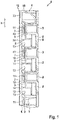
- FIG. 1 shows an exemplary embodiment of a busbar system 1, which consists essentially of a contact protection housing 4, in which three busbars 2 are accommodated.
- the busbars 2 are accessible via contacting passages 3 from the front of the housing 4, so that electrical devices and device adapters with hook-shaped holding elements can reach behind the busbars 2 after insertion via the contacting passages 3.
- the contacting of the busbars can be provided via a separate contact element of the devices or device adapters, so that the holding elements passing through the passages 3 and engaging behind the busbars 2 actually only have a holding function.
- Suitable single-pole contact terminals are, for example, in the EP 3 258 558 B1 described.
- the busbar system is three-pole and can thus be used, for example, for contacting three-pole device adapter.
- the housing 4 consists essentially of the already mentioned upper part 6 and a lower part 5 between which the busbars 2 are accommodated, the upper part 6 being detachably connected to the lower part 5 .
- the upper part 6 has on its side facing the lower part 5 a plurality of plug-in receptacles 7 extending from this side into the lower part 5 .
- the plug-in receptacles 7 are V-shaped or tapered towards their free end and have permeable openings in the advance direction x of the slide 8 .
- the slide 8 is inserted into the lower part 5 and has a plurality of latches 9 .
- the slide is arranged in the locking position, in which the latches 9 engage in the plug-in receptacle 7 intervene and set the upper part 6 on the lower part 5.
- the latches 9 are in a release position, in which the slide 8 is opposite the in figure 1 shown position is shifted upwards, upstream of the sockets, so that the upper part 6 can be lifted from the lower part 5 and thus the busbars 2 are freely accessible and can be removed from the lower part 5 if necessary.
- the pawls 9 show with their respective free end 10 in the feed direction x of the slide 8, along which the slide can be shifted from the release to the locking position.
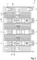
- the pawls 9 are L-shaped and fixed to a straight slide plate 12 with their shorter end. This is in detail in figure 4 shown.
- the free end 10 of the latches 9 is wedge-shaped, the latch 9 having a run-on slope 11 at its free end 10 which rises towards a shorter of the two sides of the L-shaped latch 9 .
- the latch 9 rests against a contact surface 14 via its rear side 13, which faces away from the tip of the free end (see FIG figure 1 ) of the lower part 5, so that a precise definition of the release position of the slider 8 is given.
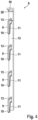
- the slider 8 when the slider 8 is released from the release position ( figure 2 ) to the locked position ( figure 3 ) is shifted, resting on its stop 20 on an outer side 18 of the housing 4, so that a precise definition of the locking position is given.
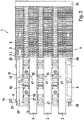
- the figures 2 and 3 also show that hook elements 15 are provided in order to prefix the busbars 2 to the lower part 5 when the upper part 6 is removed. For this purpose, after the busbars 2 have been inserted into the lower part 5, the hook elements 15 can be snapped into corresponding latching receptacles 24 in the lower part 5.
- the hook element 15 has a retaining blade 17 that protrudes beyond the busbar 2 and can be positively received in one of the contact openings 3 of the upper part 6 when the upper part 6 is placed on the lower part 5, so that the hook elements 15 are precisely arranged on the one hand and the overall height of the busbar system on the other 1 do not increase.
- the upper part 6 has a depression 21, the bottom 22 of which extends to a mounting side 23 (see figure 5 ) of the lower part 5 is sufficient, with which the lower part 5 can be brought to rest on a support, for example on a mounting plate.
- the top 6 and that Lower part 5 each have a bore 28 so that the upper part 6 can be connected to the lower part 5 and the support via a fastener extending through the bores 28 in the base 22 and the mounting side 23 into the support.
- the contact protection housing 4 has a modular structure and has complementary snap-in connectors 26 on the opposite longitudinal ends, which allow any expansion of the current busbar system.
- An end cap 25 is provided at the end, which covers the free ends of the busbars 2 so that they cannot be touched.
- the plug-in receptacles 7 can be formed on the underside of the upper part 6 in the form of V-shaped bodies integrally formed on the upper part 6, the passage openings of which are aligned with one another and in the feed direction x (cf figure 1 ) of the slider 8 are permeable.
- the depressions 21 protrude beyond their bottom sides 25 with the bore 28 in order to reach up to the mounting side 23 of the lower part 5 when the upper part 6 is placed on the lower part 5 (cf figure 1 ).
Landscapes
- Engineering & Computer Science (AREA)
- Power Engineering (AREA)
- Connector Housings Or Holding Contact Members (AREA)
- Distribution Board (AREA)
- Details Of Connecting Devices For Male And Female Coupling (AREA)
- Cable Accessories (AREA)
- Patch Boards (AREA)
Applications Claiming Priority (2)
| Application Number | Priority Date | Filing Date | Title |
|---|---|---|---|
| DE102019109629.4A DE102019109629A1 (de) | 2019-04-11 | 2019-04-11 | Stromsammelschienensystem mit mindestens einer in einem Berührungsschutzgehäuse gehaltenen Stromsammelschiene |
| PCT/DE2020/100257 WO2020207531A1 (de) | 2019-04-11 | 2020-03-30 | Stromsammelschienensystem mit mindestens einer in einem berührungsschutzgehäuse gehaltenen stromsammelschiene |
Publications (2)
| Publication Number | Publication Date |
|---|---|
| EP3954007A1 EP3954007A1 (de) | 2022-02-16 |
| EP3954007B1 true EP3954007B1 (de) | 2023-03-22 |
Family
ID=70285363
Family Applications (1)
| Application Number | Title | Priority Date | Filing Date |
|---|---|---|---|
| EP20718546.3A Active EP3954007B1 (de) | 2019-04-11 | 2020-03-30 | Stromsammelschienensystem mit mindestens einer in einem berührungsschutzgehäuse gehaltenen stromsammelschiene |
Country Status (8)
| Country | Link |
|---|---|
| US (1) | US11862946B2 (pl) |
| EP (1) | EP3954007B1 (pl) |
| KR (1) | KR102643873B1 (pl) |
| CN (1) | CN113661621B (pl) |
| DE (1) | DE102019109629A1 (pl) |
| ES (1) | ES2944307T3 (pl) |
| PL (1) | PL3954007T3 (pl) |
| WO (1) | WO2020207531A1 (pl) |
Cited By (1)
| Publication number | Priority date | Publication date | Assignee | Title |
|---|---|---|---|---|
| DE102024110871B3 (de) * | 2024-04-18 | 2025-05-15 | Rittal Gmbh & Co. Kg | Elektrische Installation mit einer Anordnung für die berührungssichere Kontaktierung mehrerer Stromsammelschienen mit Kabeldurchführung |
Families Citing this family (4)
| Publication number | Priority date | Publication date | Assignee | Title |
|---|---|---|---|---|
| CN112803334B (zh) * | 2021-03-01 | 2025-02-07 | 江苏瑞能电力设备有限公司 | 母线智能控制装置及控制方法 |
| US11842859B2 (en) * | 2021-03-26 | 2023-12-12 | Raytheon Company | Tool for fuse removal and installation |
| EP4184732B1 (en) | 2021-11-22 | 2025-03-26 | Wöhner Besitz GmbH | Power supply module |
| CN120109716B (zh) * | 2025-05-12 | 2025-07-22 | 成都高标电气有限公司 | 一种高防护密集型母线槽 |
Family Cites Families (23)
| Publication number | Priority date | Publication date | Assignee | Title |
|---|---|---|---|---|
| US5337211A (en) * | 1993-06-14 | 1994-08-09 | Eaton Corporation | Electrical load center interior panel having molded insulating support panel with snap-in bus bars |
| DE19525438A1 (de) * | 1995-07-12 | 1997-01-16 | Siemens Ag | Sammelschienen-Adaptersystem |
| EP1289085B1 (de) * | 2001-09-03 | 2010-07-14 | ABB Schweiz AG | Steckmodul für einen Niederspannungsverteiler |
| DE102005009992B3 (de) * | 2005-03-04 | 2006-06-01 | Rittal Gmbh & Co. Kg | Geräte- oder Anschlussadapter |
| JP4914434B2 (ja) | 2005-03-17 | 2012-04-11 | リッタル ゲゼルシャフト ミット ベシュレンクテル ハフツング ウント コンパニー コマンディトゲゼルシャフト | 配電盤装置 |
| DE202005017650U1 (de) * | 2005-11-09 | 2006-01-12 | Abn Werner Braun Gmbh | Zähler- und Verteilerschrank |
| FR2963491B1 (fr) * | 2010-07-30 | 2012-10-12 | Michaud Sa | Panneau de support d'appareillage electrique |
| EP2461440B1 (de) * | 2010-12-03 | 2018-05-02 | ABB Schweiz AG | Stecksystem |
| DE202011005286U1 (de) * | 2011-04-14 | 2011-08-18 | Elkutec Elektrosysteme Gmbh | Sammelschienenblock |
| CN104823327B (zh) * | 2012-10-30 | 2018-04-13 | 威德米勒界面有限公司及两合公司 | 具有能量总线系统的串联模块装置 |
| US9762038B2 (en) * | 2013-03-14 | 2017-09-12 | Schneider Electric USA, Inc. | Independent shutter system for rack-in breakers |
| EP3258558B1 (de) * | 2013-10-18 | 2018-09-19 | Wöhner GmbH & Co. KG Elektrotechnische Systeme | Berührungsschutzsystem für stromsammelschienen |
| US9312668B2 (en) * | 2014-06-20 | 2016-04-12 | Schneider Electric USA, Inc. | Arc resistant shutters |
| DE102015111560B4 (de) * | 2014-08-05 | 2018-06-28 | Rittal Gmbh & Co. Kg | Adapter für die Kontaktierung eines Leistungsschalters an einem Sammelschienensystem |
| EP3088256B1 (en) * | 2015-04-30 | 2017-11-15 | Delphi Technologies, Inc. | Busbar fixation system |
| US9564741B1 (en) * | 2015-07-17 | 2017-02-07 | Schneider Electric USA, Inc. | One axis shutter with a pin-based bus system for miniature circuit breaker load centers |
| CN205078058U (zh) * | 2015-10-22 | 2016-03-09 | 北京华钰睿能电气设备制造有限公司 | 提拉锁紧门 |
| DE102016107565A1 (de) * | 2016-04-22 | 2017-10-26 | Rittal Gmbh & Co. Kg | Anordnung für die berührungssichere Kontaktierung eines Stromsammelschienensystems |
| GB201610369D0 (en) | 2016-06-15 | 2016-07-27 | Rolls Royce Plc | Control of an electrical converter |
| CN106159851A (zh) * | 2016-08-28 | 2016-11-23 | 威腾电气集团股份有限公司 | 一种母线槽精准连接的防错相装置 |
| EP3454436B1 (en) * | 2017-09-11 | 2024-07-17 | ABB S.p.A. | Compartment-partitioning and busbar-supporting device in a cabinet for a low voltage electrical switchboard |
| CN208461223U (zh) * | 2018-01-27 | 2019-02-01 | 西安秦电仪表有限责任公司 | 一种固体环网柜单元柜连接结构 |
| CN109066545A (zh) * | 2018-09-11 | 2018-12-21 | 镇江宝源电仪设备有限公司 | 一种便于安装的母线槽 |
-
2019
- 2019-04-11 DE DE102019109629.4A patent/DE102019109629A1/de active Pending
-
2020
- 2020-03-30 ES ES20718546T patent/ES2944307T3/es active Active
- 2020-03-30 PL PL20718546.3T patent/PL3954007T3/pl unknown
- 2020-03-30 EP EP20718546.3A patent/EP3954007B1/de active Active
- 2020-03-30 US US17/602,833 patent/US11862946B2/en active Active
- 2020-03-30 CN CN202080027960.0A patent/CN113661621B/zh active Active
- 2020-03-30 WO PCT/DE2020/100257 patent/WO2020207531A1/de not_active Ceased
- 2020-03-30 KR KR1020217036404A patent/KR102643873B1/ko active Active
Cited By (2)
| Publication number | Priority date | Publication date | Assignee | Title |
|---|---|---|---|---|
| DE102024110871B3 (de) * | 2024-04-18 | 2025-05-15 | Rittal Gmbh & Co. Kg | Elektrische Installation mit einer Anordnung für die berührungssichere Kontaktierung mehrerer Stromsammelschienen mit Kabeldurchführung |
| WO2025218850A1 (de) | 2024-04-18 | 2025-10-23 | Rittal Gmbh & Co. Kg | Anordnung für die berührungssichere kontaktierung mehrerer stromsammelschienen mit kabeldurchführung |
Also Published As
| Publication number | Publication date |
|---|---|
| KR20210144893A (ko) | 2021-11-30 |
| CN113661621A (zh) | 2021-11-16 |
| EP3954007A1 (de) | 2022-02-16 |
| US20220149599A1 (en) | 2022-05-12 |
| US11862946B2 (en) | 2024-01-02 |
| CN113661621B (zh) | 2024-07-19 |
| PL3954007T3 (pl) | 2023-07-24 |
| ES2944307T3 (es) | 2023-06-20 |
| WO2020207531A1 (de) | 2020-10-15 |
| DE102019109629A1 (de) | 2020-10-15 |
| KR102643873B1 (ko) | 2024-03-07 |
Similar Documents
| Publication | Publication Date | Title |
|---|---|---|
| EP3954007B1 (de) | Stromsammelschienensystem mit mindestens einer in einem berührungsschutzgehäuse gehaltenen stromsammelschiene | |
| EP3275055B1 (de) | Halterahmen für modulares steckverbindersystem | |
| EP2339701B1 (de) | Leiterplattensteckverbinder mit Verriegelungsvorrichtung | |
| EP3446381B1 (de) | Anordnung für die berührungssichere kontaktierung eines stromsammelschienensystems | |
| EP2839544B1 (de) | Prüfklemmenblock | |
| EP3639334B1 (de) | Tragschienenbefestigung | |
| DE202013104785U1 (de) | Reihenbausteinanordnung mit einem Energiebussystem | |
| EP2606534A1 (de) | Tragschienen- und modulverrastung | |
| DE202008015309U1 (de) | Montagesystem für elektrische und/oder mechanische Komponenten | |
| EP2738884B1 (de) | Montage einer Anschlussvorrichtung | |
| EP2878052A1 (de) | Montagesystem für die anordnung von beispielsweise elektrischen einrichtungen insbesondere in schaltschränken | |
| EP0762581A1 (de) | Vorrichtung zum Befestigen eines elektrischen Gerätes auf einem Adapter | |
| EP3142831A1 (de) | Werkzeughalteranordnung für eine lochrasterplatte | |
| DE102013110788B4 (de) | Sammelschienen-Adapter | |
| EP3440745B1 (de) | Wabenbaustein zur ausbildung einer rangierwabe, rangierwabe und werkzeug zum lösen eines wabenbausteins aus einer rangierwabe | |
| DE2914192A1 (de) | Schaltanlagenreihenklemme mit zugeordneter isolier-trennwand | |
| DE102019009196A1 (de) | Stromsammelschienensystem mit einem eine Verriegelungsanzeige aufweisenden Berührungsschutzgehäuse sowie ein entsprechendes Verfahren | |
| EP3200294A1 (de) | Anordnung einer elektrischen schaltleiste und einer stationären aufnahme für diese | |
| DE102019009195A1 (de) | Stromsammelschienensystem mit vereinfachter Montage Verfahren auf einer Unterlage sowie ein entsprechendes Verfahren | |
| DE102012103251B4 (de) | Niederspannungs- oder Mittelspannungs-Schaltanlage mit einer Berührungsschutzabdeckung | |
| EP1505701A1 (de) | Auf Stromschienen anzuordnendes elektrischesTeil | |
| DE10135662A1 (de) | Gerätebecherrahmen für Unterfluranwendungen | |
| EP4199271B1 (de) | Haltevorrichtung für kontaktierungsvorrichtungen | |
| EP3931924B1 (de) | Schaltschrankanordnung mit einem schaltschrank und mindestens einer steckdosenleiste | |
| DE10340209B4 (de) | Elektrisches Gerät mit Halte/-Lösevorrichtung |
Legal Events
| Date | Code | Title | Description |
|---|---|---|---|
| STAA | Information on the status of an ep patent application or granted ep patent |
Free format text: STATUS: UNKNOWN |
|
| STAA | Information on the status of an ep patent application or granted ep patent |
Free format text: STATUS: THE INTERNATIONAL PUBLICATION HAS BEEN MADE |
|
| PUAI | Public reference made under article 153(3) epc to a published international application that has entered the european phase |
Free format text: ORIGINAL CODE: 0009012 |
|
| STAA | Information on the status of an ep patent application or granted ep patent |
Free format text: STATUS: REQUEST FOR EXAMINATION WAS MADE |
|
| 17P | Request for examination filed |
Effective date: 20210920 |
|
| AK | Designated contracting states |
Kind code of ref document: A1 Designated state(s): AL AT BE BG CH CY CZ DE DK EE ES FI FR GB GR HR HU IE IS IT LI LT LU LV MC MK MT NL NO PL PT RO RS SE SI SK SM TR |
|
| DAV | Request for validation of the european patent (deleted) | ||
| DAX | Request for extension of the european patent (deleted) | ||
| GRAP | Despatch of communication of intention to grant a patent |
Free format text: ORIGINAL CODE: EPIDOSNIGR1 |
|
| STAA | Information on the status of an ep patent application or granted ep patent |
Free format text: STATUS: GRANT OF PATENT IS INTENDED |
|
| INTG | Intention to grant announced |
Effective date: 20221018 |
|
| GRAS | Grant fee paid |
Free format text: ORIGINAL CODE: EPIDOSNIGR3 |
|
| GRAA | (expected) grant |
Free format text: ORIGINAL CODE: 0009210 |
|
| STAA | Information on the status of an ep patent application or granted ep patent |
Free format text: STATUS: THE PATENT HAS BEEN GRANTED |
|
| AK | Designated contracting states |
Kind code of ref document: B1 Designated state(s): AL AT BE BG CH CY CZ DE DK EE ES FI FR GB GR HR HU IE IS IT LI LT LU LV MC MK MT NL NO PL PT RO RS SE SI SK SM TR |
|
| REG | Reference to a national code |
Ref country code: GB Ref legal event code: FG4D Free format text: NOT ENGLISH |
|
| REG | Reference to a national code |
Ref country code: CH Ref legal event code: EP |
|
| REG | Reference to a national code |
Ref country code: IE Ref legal event code: FG4D Free format text: LANGUAGE OF EP DOCUMENT: GERMAN |
|
| REG | Reference to a national code |
Ref country code: DE Ref legal event code: R096 Ref document number: 502020002809 Country of ref document: DE |
|
| REG | Reference to a national code |
Ref country code: AT Ref legal event code: REF Ref document number: 1555871 Country of ref document: AT Kind code of ref document: T Effective date: 20230415 |
|
| REG | Reference to a national code |
Ref country code: SE Ref legal event code: TRGR |
|
| REG | Reference to a national code |
Ref country code: ES Ref legal event code: FG2A Ref document number: 2944307 Country of ref document: ES Kind code of ref document: T3 Effective date: 20230620 |
|
| P01 | Opt-out of the competence of the unified patent court (upc) registered |
Effective date: 20230525 |
|
| REG | Reference to a national code |
Ref country code: LT Ref legal event code: MG9D |
|
| REG | Reference to a national code |
Ref country code: NL Ref legal event code: MP Effective date: 20230322 |
|
| PG25 | Lapsed in a contracting state [announced via postgrant information from national office to epo] |
Ref country code: RS Free format text: LAPSE BECAUSE OF FAILURE TO SUBMIT A TRANSLATION OF THE DESCRIPTION OR TO PAY THE FEE WITHIN THE PRESCRIBED TIME-LIMIT Effective date: 20230322 Ref country code: NO Free format text: LAPSE BECAUSE OF FAILURE TO SUBMIT A TRANSLATION OF THE DESCRIPTION OR TO PAY THE FEE WITHIN THE PRESCRIBED TIME-LIMIT Effective date: 20230622 Ref country code: LV Free format text: LAPSE BECAUSE OF FAILURE TO SUBMIT A TRANSLATION OF THE DESCRIPTION OR TO PAY THE FEE WITHIN THE PRESCRIBED TIME-LIMIT Effective date: 20230322 Ref country code: LT Free format text: LAPSE BECAUSE OF FAILURE TO SUBMIT A TRANSLATION OF THE DESCRIPTION OR TO PAY THE FEE WITHIN THE PRESCRIBED TIME-LIMIT Effective date: 20230322 Ref country code: HR Free format text: LAPSE BECAUSE OF FAILURE TO SUBMIT A TRANSLATION OF THE DESCRIPTION OR TO PAY THE FEE WITHIN THE PRESCRIBED TIME-LIMIT Effective date: 20230322 |
|
| PG25 | Lapsed in a contracting state [announced via postgrant information from national office to epo] |
Ref country code: NL Free format text: LAPSE BECAUSE OF FAILURE TO SUBMIT A TRANSLATION OF THE DESCRIPTION OR TO PAY THE FEE WITHIN THE PRESCRIBED TIME-LIMIT Effective date: 20230322 Ref country code: GR Free format text: LAPSE BECAUSE OF FAILURE TO SUBMIT A TRANSLATION OF THE DESCRIPTION OR TO PAY THE FEE WITHIN THE PRESCRIBED TIME-LIMIT Effective date: 20230623 Ref country code: FI Free format text: LAPSE BECAUSE OF FAILURE TO SUBMIT A TRANSLATION OF THE DESCRIPTION OR TO PAY THE FEE WITHIN THE PRESCRIBED TIME-LIMIT Effective date: 20230322 |
|
| PG25 | Lapsed in a contracting state [announced via postgrant information from national office to epo] |
Ref country code: SM Free format text: LAPSE BECAUSE OF FAILURE TO SUBMIT A TRANSLATION OF THE DESCRIPTION OR TO PAY THE FEE WITHIN THE PRESCRIBED TIME-LIMIT Effective date: 20230322 Ref country code: RO Free format text: LAPSE BECAUSE OF FAILURE TO SUBMIT A TRANSLATION OF THE DESCRIPTION OR TO PAY THE FEE WITHIN THE PRESCRIBED TIME-LIMIT Effective date: 20230322 Ref country code: PT Free format text: LAPSE BECAUSE OF FAILURE TO SUBMIT A TRANSLATION OF THE DESCRIPTION OR TO PAY THE FEE WITHIN THE PRESCRIBED TIME-LIMIT Effective date: 20230724 Ref country code: EE Free format text: LAPSE BECAUSE OF FAILURE TO SUBMIT A TRANSLATION OF THE DESCRIPTION OR TO PAY THE FEE WITHIN THE PRESCRIBED TIME-LIMIT Effective date: 20230322 |
|
| PG25 | Lapsed in a contracting state [announced via postgrant information from national office to epo] |
Ref country code: SK Free format text: LAPSE BECAUSE OF FAILURE TO SUBMIT A TRANSLATION OF THE DESCRIPTION OR TO PAY THE FEE WITHIN THE PRESCRIBED TIME-LIMIT Effective date: 20230322 Ref country code: IS Free format text: LAPSE BECAUSE OF FAILURE TO SUBMIT A TRANSLATION OF THE DESCRIPTION OR TO PAY THE FEE WITHIN THE PRESCRIBED TIME-LIMIT Effective date: 20230722 |
|
| REG | Reference to a national code |
Ref country code: BE Ref legal event code: MM Effective date: 20230331 |
|
| PG25 | Lapsed in a contracting state [announced via postgrant information from national office to epo] |
Ref country code: LU Free format text: LAPSE BECAUSE OF NON-PAYMENT OF DUE FEES Effective date: 20230330 |
|
| REG | Reference to a national code |
Ref country code: DE Ref legal event code: R097 Ref document number: 502020002809 Country of ref document: DE |
|
| PG25 | Lapsed in a contracting state [announced via postgrant information from national office to epo] |
Ref country code: MC Free format text: LAPSE BECAUSE OF FAILURE TO SUBMIT A TRANSLATION OF THE DESCRIPTION OR TO PAY THE FEE WITHIN THE PRESCRIBED TIME-LIMIT Effective date: 20230322 |
|
| REG | Reference to a national code |
Ref country code: IE Ref legal event code: MM4A |
|
| PLBE | No opposition filed within time limit |
Free format text: ORIGINAL CODE: 0009261 |
|
| STAA | Information on the status of an ep patent application or granted ep patent |
Free format text: STATUS: NO OPPOSITION FILED WITHIN TIME LIMIT |
|
| PG25 | Lapsed in a contracting state [announced via postgrant information from national office to epo] |
Ref country code: SI Free format text: LAPSE BECAUSE OF FAILURE TO SUBMIT A TRANSLATION OF THE DESCRIPTION OR TO PAY THE FEE WITHIN THE PRESCRIBED TIME-LIMIT Effective date: 20230322 Ref country code: MC Free format text: LAPSE BECAUSE OF FAILURE TO SUBMIT A TRANSLATION OF THE DESCRIPTION OR TO PAY THE FEE WITHIN THE PRESCRIBED TIME-LIMIT Effective date: 20230322 Ref country code: IE Free format text: LAPSE BECAUSE OF NON-PAYMENT OF DUE FEES Effective date: 20230330 Ref country code: DK Free format text: LAPSE BECAUSE OF FAILURE TO SUBMIT A TRANSLATION OF THE DESCRIPTION OR TO PAY THE FEE WITHIN THE PRESCRIBED TIME-LIMIT Effective date: 20230322 Ref country code: CZ Free format text: LAPSE BECAUSE OF FAILURE TO SUBMIT A TRANSLATION OF THE DESCRIPTION OR TO PAY THE FEE WITHIN THE PRESCRIBED TIME-LIMIT Effective date: 20230322 |
|
| 26N | No opposition filed |
Effective date: 20240102 |
|
| PG25 | Lapsed in a contracting state [announced via postgrant information from national office to epo] |
Ref country code: BE Free format text: LAPSE BECAUSE OF NON-PAYMENT OF DUE FEES Effective date: 20230331 |
|
| PG25 | Lapsed in a contracting state [announced via postgrant information from national office to epo] |
Ref country code: BG Free format text: LAPSE BECAUSE OF FAILURE TO SUBMIT A TRANSLATION OF THE DESCRIPTION OR TO PAY THE FEE WITHIN THE PRESCRIBED TIME-LIMIT Effective date: 20230322 |
|
| GBPC | Gb: european patent ceased through non-payment of renewal fee |
Effective date: 20240330 |
|
| PG25 | Lapsed in a contracting state [announced via postgrant information from national office to epo] |
Ref country code: BG Free format text: LAPSE BECAUSE OF FAILURE TO SUBMIT A TRANSLATION OF THE DESCRIPTION OR TO PAY THE FEE WITHIN THE PRESCRIBED TIME-LIMIT Effective date: 20230322 |
|
| PG25 | Lapsed in a contracting state [announced via postgrant information from national office to epo] |
Ref country code: GB Free format text: LAPSE BECAUSE OF NON-PAYMENT OF DUE FEES Effective date: 20240330 |
|
| PG25 | Lapsed in a contracting state [announced via postgrant information from national office to epo] |
Ref country code: GB Free format text: LAPSE BECAUSE OF NON-PAYMENT OF DUE FEES Effective date: 20240330 |
|
| PGFP | Annual fee paid to national office [announced via postgrant information from national office to epo] |
Ref country code: SE Payment date: 20250311 Year of fee payment: 6 |
|
| PGFP | Annual fee paid to national office [announced via postgrant information from national office to epo] |
Ref country code: DE Payment date: 20250319 Year of fee payment: 6 |
|
| PGFP | Annual fee paid to national office [announced via postgrant information from national office to epo] |
Ref country code: AT Payment date: 20250319 Year of fee payment: 6 |
|
| PGFP | Annual fee paid to national office [announced via postgrant information from national office to epo] |
Ref country code: FR Payment date: 20250324 Year of fee payment: 6 Ref country code: PL Payment date: 20250314 Year of fee payment: 6 |
|
| PGFP | Annual fee paid to national office [announced via postgrant information from national office to epo] |
Ref country code: TR Payment date: 20250321 Year of fee payment: 6 |
|
| PGFP | Annual fee paid to national office [announced via postgrant information from national office to epo] |
Ref country code: ES Payment date: 20250416 Year of fee payment: 6 |
|
| PGFP | Annual fee paid to national office [announced via postgrant information from national office to epo] |
Ref country code: IT Payment date: 20250331 Year of fee payment: 6 |
|
| PGFP | Annual fee paid to national office [announced via postgrant information from national office to epo] |
Ref country code: CH Payment date: 20250401 Year of fee payment: 6 |
|
| PG25 | Lapsed in a contracting state [announced via postgrant information from national office to epo] |
Ref country code: CY Free format text: LAPSE BECAUSE OF FAILURE TO SUBMIT A TRANSLATION OF THE DESCRIPTION OR TO PAY THE FEE WITHIN THE PRESCRIBED TIME-LIMIT; INVALID AB INITIO Effective date: 20200330 |
|
| PG25 | Lapsed in a contracting state [announced via postgrant information from national office to epo] |
Ref country code: HU Free format text: LAPSE BECAUSE OF FAILURE TO SUBMIT A TRANSLATION OF THE DESCRIPTION OR TO PAY THE FEE WITHIN THE PRESCRIBED TIME-LIMIT; INVALID AB INITIO Effective date: 20200330 |