EP3953552B1 - Öffnungsvorrichtung für ein kühlgerät - Google Patents
Öffnungsvorrichtung für ein kühlgerät Download PDFInfo
- Publication number
- EP3953552B1 EP3953552B1 EP20712950.3A EP20712950A EP3953552B1 EP 3953552 B1 EP3953552 B1 EP 3953552B1 EP 20712950 A EP20712950 A EP 20712950A EP 3953552 B1 EP3953552 B1 EP 3953552B1
- Authority
- EP
- European Patent Office
- Prior art keywords
- opening device
- mounting base
- functional unit
- door
- ejection element
- Prior art date
- Legal status (The legal status is an assumption and is not a legal conclusion. Google has not performed a legal analysis and makes no representation as to the accuracy of the status listed.)
- Active
Links
Images


Classifications
-
- F—MECHANICAL ENGINEERING; LIGHTING; HEATING; WEAPONS; BLASTING
- F25—REFRIGERATION OR COOLING; COMBINED HEATING AND REFRIGERATION SYSTEMS; HEAT PUMP SYSTEMS; MANUFACTURE OR STORAGE OF ICE; LIQUEFACTION SOLIDIFICATION OF GASES
- F25D—REFRIGERATORS; COLD ROOMS; ICE-BOXES; COOLING OR FREEZING APPARATUS NOT OTHERWISE PROVIDED FOR
- F25D23/00—General constructional features
- F25D23/10—Arrangements for mounting in particular locations, e.g. for built-in type, for corner type
-
- E—FIXED CONSTRUCTIONS
- E05—LOCKS; KEYS; WINDOW OR DOOR FITTINGS; SAFES
- E05F—DEVICES FOR MOVING WINGS INTO OPEN OR CLOSED POSITION; CHECKS FOR WINGS; WING FITTINGS NOT OTHERWISE PROVIDED FOR, CONCERNED WITH THE FUNCTIONING OF THE WING
- E05F15/00—Power-operated mechanisms for wings
- E05F15/60—Power-operated mechanisms for wings using electrical actuators
- E05F15/603—Power-operated mechanisms for wings using electrical actuators using rotary electromotors
- E05F15/611—Power-operated mechanisms for wings using electrical actuators using rotary electromotors for swinging wings
- E05F15/616—Power-operated mechanisms for wings using electrical actuators using rotary electromotors for swinging wings operated by push-pull mechanisms
-
- F—MECHANICAL ENGINEERING; LIGHTING; HEATING; WEAPONS; BLASTING
- F25—REFRIGERATION OR COOLING; COMBINED HEATING AND REFRIGERATION SYSTEMS; HEAT PUMP SYSTEMS; MANUFACTURE OR STORAGE OF ICE; LIQUEFACTION SOLIDIFICATION OF GASES
- F25D—REFRIGERATORS; COLD ROOMS; ICE-BOXES; COOLING OR FREEZING APPARATUS NOT OTHERWISE PROVIDED FOR
- F25D23/00—General constructional features
- F25D23/02—Doors; Covers
- F25D23/028—Details
-
- E—FIXED CONSTRUCTIONS
- E05—LOCKS; KEYS; WINDOW OR DOOR FITTINGS; SAFES
- E05Y—INDEXING SCHEME ASSOCIATED WITH SUBCLASSES E05D AND E05F, RELATING TO CONSTRUCTION ELEMENTS, ELECTRIC CONTROL, POWER SUPPLY, POWER SIGNAL OR TRANSMISSION, USER INTERFACES, MOUNTING OR COUPLING, DETAILS, ACCESSORIES, AUXILIARY OPERATIONS NOT OTHERWISE PROVIDED FOR, APPLICATION THEREOF
- E05Y2201/00—Constructional elements; Accessories therefor
- E05Y2201/40—Motors; Magnets; Springs; Weights; Accessories therefor
- E05Y2201/404—Function thereof
- E05Y2201/422—Function thereof for opening
- E05Y2201/426—Function thereof for opening for the initial opening movement
-
- E—FIXED CONSTRUCTIONS
- E05—LOCKS; KEYS; WINDOW OR DOOR FITTINGS; SAFES
- E05Y—INDEXING SCHEME ASSOCIATED WITH SUBCLASSES E05D AND E05F, RELATING TO CONSTRUCTION ELEMENTS, ELECTRIC CONTROL, POWER SUPPLY, POWER SIGNAL OR TRANSMISSION, USER INTERFACES, MOUNTING OR COUPLING, DETAILS, ACCESSORIES, AUXILIARY OPERATIONS NOT OTHERWISE PROVIDED FOR, APPLICATION THEREOF
- E05Y2201/00—Constructional elements; Accessories therefor
- E05Y2201/60—Suspension or transmission members; Accessories therefor
- E05Y2201/622—Suspension or transmission members elements
- E05Y2201/624—Arms
-
- E—FIXED CONSTRUCTIONS
- E05—LOCKS; KEYS; WINDOW OR DOOR FITTINGS; SAFES
- E05Y—INDEXING SCHEME ASSOCIATED WITH SUBCLASSES E05D AND E05F, RELATING TO CONSTRUCTION ELEMENTS, ELECTRIC CONTROL, POWER SUPPLY, POWER SIGNAL OR TRANSMISSION, USER INTERFACES, MOUNTING OR COUPLING, DETAILS, ACCESSORIES, AUXILIARY OPERATIONS NOT OTHERWISE PROVIDED FOR, APPLICATION THEREOF
- E05Y2400/00—Electronic control; Electrical power; Power supply; Power or signal transmission; User interfaces
- E05Y2400/65—Power or signal transmission
-
- E—FIXED CONSTRUCTIONS
- E05—LOCKS; KEYS; WINDOW OR DOOR FITTINGS; SAFES
- E05Y—INDEXING SCHEME ASSOCIATED WITH SUBCLASSES E05D AND E05F, RELATING TO CONSTRUCTION ELEMENTS, ELECTRIC CONTROL, POWER SUPPLY, POWER SIGNAL OR TRANSMISSION, USER INTERFACES, MOUNTING OR COUPLING, DETAILS, ACCESSORIES, AUXILIARY OPERATIONS NOT OTHERWISE PROVIDED FOR, APPLICATION THEREOF
- E05Y2600/00—Mounting or coupling arrangements for elements provided for in this subclass
- E05Y2600/50—Mounting methods; Positioning
- E05Y2600/52—Toolless
- E05Y2600/528—Hooking, e.g. using bayonets; Locking
-
- E—FIXED CONSTRUCTIONS
- E05—LOCKS; KEYS; WINDOW OR DOOR FITTINGS; SAFES
- E05Y—INDEXING SCHEME ASSOCIATED WITH SUBCLASSES E05D AND E05F, RELATING TO CONSTRUCTION ELEMENTS, ELECTRIC CONTROL, POWER SUPPLY, POWER SIGNAL OR TRANSMISSION, USER INTERFACES, MOUNTING OR COUPLING, DETAILS, ACCESSORIES, AUXILIARY OPERATIONS NOT OTHERWISE PROVIDED FOR, APPLICATION THEREOF
- E05Y2600/00—Mounting or coupling arrangements for elements provided for in this subclass
- E05Y2600/60—Mounting or coupling members; Accessories therefor
- E05Y2600/626—Plates or brackets
-
- E—FIXED CONSTRUCTIONS
- E05—LOCKS; KEYS; WINDOW OR DOOR FITTINGS; SAFES
- E05Y—INDEXING SCHEME ASSOCIATED WITH SUBCLASSES E05D AND E05F, RELATING TO CONSTRUCTION ELEMENTS, ELECTRIC CONTROL, POWER SUPPLY, POWER SIGNAL OR TRANSMISSION, USER INTERFACES, MOUNTING OR COUPLING, DETAILS, ACCESSORIES, AUXILIARY OPERATIONS NOT OTHERWISE PROVIDED FOR, APPLICATION THEREOF
- E05Y2900/00—Application of doors, windows, wings or fittings thereof
- E05Y2900/30—Application of doors, windows, wings or fittings thereof for domestic appliances
- E05Y2900/31—Application of doors, windows, wings or fittings thereof for domestic appliances for refrigerators
-
- F—MECHANICAL ENGINEERING; LIGHTING; HEATING; WEAPONS; BLASTING
- F25—REFRIGERATION OR COOLING; COMBINED HEATING AND REFRIGERATION SYSTEMS; HEAT PUMP SYSTEMS; MANUFACTURE OR STORAGE OF ICE; LIQUEFACTION SOLIDIFICATION OF GASES
- F25D—REFRIGERATORS; COLD ROOMS; ICE-BOXES; COOLING OR FREEZING APPARATUS NOT OTHERWISE PROVIDED FOR
- F25D2400/00—General features of, or devices for refrigerators, cold rooms, ice-boxes, or for cooling or freezing apparatus not covered by any other subclass
- F25D2400/40—Refrigerating devices characterised by electrical wiring
Definitions
- the invention relates to an opening device for a refrigeration appliance with a door arrangement, the opening device having a mounting base which can be mounted on fastening devices provided for a door hinge of the refrigeration appliance, and having a functional unit with an ejection element which can be extended in an electrically controlled manner.
- Common household refrigerators such as refrigerators or freezers, generally have a pivoting door that is sealed off from the body of the refrigerator with a peripheral seal.
- the circumferential seal is typically designed as a magnetic seal that applies locking forces between the door and the body.
- the door hinges can be equipped with a self-closing function that provides additional locking forces.
- the opening devices mentioned at the outset are known, in which an ejection element can be extended from a housing in an electrically driven manner, with which the door of the cooling device is pushed open at least far enough that the door can be easily reached from behind and then opened completely manually .
- Such an opening device is, for example, from the publication EP 2 292 995 B1 known.
- the opening device described there is mounted on an upper side of the refrigerator and presses with its ejection element against an upper, projecting edge of the door of the refrigerator.
- the opening device has a coil in which an armature is slidably mounted.
- the armature is held in a rest position by a spring element and moves out when the coil is energized.
- the disengaging armature acts on the door via a lever mechanism in order to open it at least a little.
- An arrangement of the opening device on top of the cooling device is often undesirable for design reasons.
- the top of the cooling unit can only be used as a storage space to a limited extent.
- a cooling device with an opening device positioned in this way is only suitable to a limited extent for installation in a furniture body, since the opening device, which protrudes upwards beyond the insulating body of the cooling device, would result in an only partially closed gap between the cooling device and a top plate or a shelf of the furniture body .
- a refrigerator having an opening and/or closing device inserted in a pocket formed on the front side of an insulating body.
- An electrical socket is arranged in the pocket, into which a plug arranged on the opening and/or closing device engages.
- the pamphlet WO 2018/007240 A1 shows an opening device of the type mentioned. This is characterized in that it can be mounted on provided fastening devices for a door hinge of the refrigerator using a mounting bracket on a front end face of an insulating body of the refrigerator. Furthermore, the opening device is designed in such a way that its ejection element acts on an area of the door arrangement which is outside of the seal.
- the opening device thus advantageously uses the installation space for the door hinges that is provided as standard in the refrigerator and also makes use of the fastening devices for the door hinges that have already been prepared in this context. When the opening device is installed in this installation space, a connection cable must be routed from this installation space between the cooling device and a piece of furniture in which the cooling device is installed. This connection diagram makes it difficult to replace the opening device in the event of service or repairs.
- An opening device is characterized in that the mounting base has contacts and the functional unit has counter-contacts, the contacts and the counter-contacts contacting one another when the functional unit is fastened to the mounting base to supply power to the functional unit.
- the functional unit can be easily replaced without the wiring of a connecting cable having to be disconnected or reconnected, or without a connecting cable having to be rerouted .
- the functional unit can be replaced, for example, for repair, service and/or cleaning purposes. The replacement can be performed by the user or an unskilled service technician.
- the contacts of the mounting base are connected to a connection cable that has power supply lines and, if necessary, signal lines.
- the mounting base and the functional unit have fastening means which engage in one another.
- the fastening means are preferably designed in such a way that the functional unit can be fastened to the mounting base without the use of tools.
- the fastening means include, for example, locking means, guide webs, hooks, eyes and/or undercuts.
- the mounting base In order to fasten the mounting base, it has mounting bores for connection to the cooling device and preferably also for connection to a furniture body into which the cooling device is accommodated (slide in).
- the mounting base can be L-shaped, for example.
- the preferred installation location for the opening device is the standard installation space provided for the door hinges in the refrigerator. It is then particularly advantageous to also use the fastening devices for the door hinges, which have already been prepared in this connection, for fastening the mounting base.
- an opening device according to the invention can be easily retrofitted for a large number of cooling devices that are already available on the market.
- no other space that can be used, for example on a top side of the cooling device is occupied.
- an intervention in the insulating body, which goes beyond the fastening devices of the door hinges that are present anyway, is not necessary.
- a minimum distance between the furniture body and the cooling device for the passage of the connecting cable is defined via the mounting base.
- the housing of the opening device advantageously has a depth of less than 60 millimeters (mm), preferably less than 47 mm or preferably between 38 and 47 mm.
- the ejection element has a maximum stroke of 40 mm to 80 mm.
- the door arrangement can be opened far enough for the locking force of the (magnetic) seal and the negative pressure in the interior of the refrigerator to be overcome.
- the door arrangement can then be easily reached from behind to open it fully.
- the door arrangement is preferably only opened so far by the opening device that it is still in the self-closing area of the door hinges if they are equipped with a self-closing mechanism. If the door arrangement is not opened manually, it then closes automatically after the ejection element is retracted.
- the ejection element is pivotably mounted on a base body and, in a non-pivoted position, surrounds the base body in the form of a hood on at least four sides.
- the opening device preferably has a pivoting element which is pivotably mounted on the base body and has at least one internal gear wheel segment which is coupled to an electric motor via a drive gear wheel and can be pivoted by the motor relative to the base body.
- the pivoting element moves the ejection element with it, preferably via at least one roller which is arranged eccentrically on the pivoting element and moves along a guide curve in the ejection element.
- the guide curve enables a larger pivoting angle of the ejection element than would result solely from the rotary movement of the pivoting element.
- the angle dependency of the movement of the ejection element can also be influenced as a function of the angle of rotation of the pivoting element by shaping the guide curve. In this way, an ejection movement that is as effective as possible can be achieved, which at the beginning of the movement sequence has a large ejection force, which is advantageous in order to overcome magnetic locking forces of the door arrangement of the refrigerator. This is followed by a higher speed burst to allow the door assembly to be burst open far enough.
- the opening device has an apron which is pivotably mounted on the base body or the ejection element and which extends between the base body and the ejection element as protection against pinching.
- the apron is preferably also moved in a forcibly guided manner in at least one movement direction by the pivoting element and/or the ejection element. A forced movement of the apron ensures that it is always in a suitable position in which it prevents a finger, for example, from getting caught when the ejection element is retracted again.
- the electric motor is coupled to the drive gear wheel via a worm gear.
- a suitable transmission ratio can be achieved in a space-saving manner with just one gear stage.
- the electric motor is preferably fastened in or on the base body in a vibration-damping manner. In this way, operation of the opening device is as silent as possible.
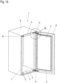
- a cooling device 1 is shown in an isometric representation.
- the refrigerator 1 can be, for example, a refrigerator or a freezer for use in the home or for commercial use.
- the cooling device 1 has a heat-insulated body, referred to below as the insulating body 2, whose interior space and front end face 3 can be seen in the figures shown.
- the insulating body 2 is assigned a thermally insulated door, referred to below as the insulating door 4, which has a peripheral seal 5, usually a magnetic seal.
- the seal 5 lies circumferentially on the front face 3 of the insulating body 2 and thus hermetically seals the interior of the insulating body 2 .
- the insulating body 2 is built into a furniture body 6, to which a body door 8 is assigned, which rests against a front face 7 of the furniture body 6 in the closed state.
- the carcass door 8 and the insulating door 4 form a unit that is firmly connected to one another.
- the body door 8 can also be connected to the insulating door as a so-called trailing door.
- the corpus door 8 protrudes outwards over the insulating door 4 on all sides.
- the insulating door 4 is pivotably connected to the insulating body 2 of the cooling device 1 via door hinges 9 .
- the actual joint mechanism of the respective door hinge 9 is arranged above or below the insulating door 4, so that when the cooling device 1 is closed it lies outside the insulated interior of the insulating body 2.
- the body door 8 is in the Figures 1a and 1b not visible door connector connected to the insulating door 4 to form a unit and carried by the insulating door 4.
- the door connector is usually also used to align the carcass door 8 relative to the insulating door 4 in all three spatial directions, if necessary. In this way, a gap-free fit of both doors on the respective end face of the corresponding body can be achieved.
- An opening device 10 is arranged in the upper left corner area of the insulating body 2, which is used for the electrically driven opening of the door arrangement, i.e. the unit consisting of the body door 8 and the insulating door 4.
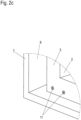
- the arrangement of the opening device 10 and the door hinge 9 in the upper area of the refrigerator 1 is shown in the detail enlargements in FIGS figures 2a and 2b shown again in more detail.
- the door hinge 9 used is, for example, a so-called seven-bar hinge, which has seven different points of articulation. Such joints have established themselves as a standard in refrigeration devices, since they can be used to achieve a suitably guided opening movement of the door arrangement.
- a space of a certain width, depth and height extends in the horizontal direction along the front face 3, the height extends in the vertical direction along the face 3 and the depth extends in a direction perpendicular to the face 3 of the insulating body 2.
- the depth is specified as standard for the door hinges 9 that are usually used and is approximately 42 mm.
- the depth indicates the distance between the front surface 3 of the insulating body 2 and the surface of the body door 8 facing the insulating body 2 .
- the door hinge 9 bears against the two surfaces mentioned, the front end face 3 or the inner surface of the carcass door 8 with contact surfaces and is fastened to these elements with fastening means, usually screws.
- the position of the fasteners is also specified as standard.
- the insulating body 2 of the cooling device 1 are prefabricated fastening devices, eg screw-in options arranged so that the door hinge 9 can be screwed onto the end face 3 in the corner area.
- the fastening devices can be provided, for example, by inserted or pressed-in threaded bushes.
- the refrigeration device 1 allows, as is usual with refrigeration devices, a left-hand or right-hand door stop.
- the fastening devices mentioned for the door hinge(s) 9 are provided not only on the right-hand side of the insulating body 2, but in mirror image on the left-hand side.
- the door hinges 9 can thus also be screwed onto the left side of the refrigerator in the upper left or lower left corner without any other structural changes. If the door hinges 9 are not symmetrical, they are swapped over crosswise when the door hinges change, i.e. the upper right door hinge 9 is inserted at the bottom left and the lower right door hinge 9 at the top left.
- the installation space that would be available for the upper one of the door hinges 9 when the door was hinged on the left is occupied by the opening device 10 .
- the opening device 10 is advantageously not only positioned in this installation space, but also uses the prepared fastening devices for the door hinge 9. With a door hinged on the left, the door hinge 9 would use these fastening devices on the left side, whereas the opening device 10, in the illustrated state, is from the top Door hinge 9 used mounting options in the upper right corner of the insulator 9 would use.
- an opening device 10 can be arranged not only in the upper but also in the lower area of the cooling device 1 or both in the upper and in the lower area.
- the opening device 10 could therefore also use the fastening devices for the lower of the two door hinges 9 on the side on which the door hinge is not installed.
- the fasteners mentioned in the lower left corner of the refrigerator 1 are in the Figures 1a and 1b shown.
- the Figure 2c shows the lower left corner area of the cooling device 1 in an enlarged detail.
- the fastening devices are in this case threaded inserts 11 in the end face 3 of the insulating body 2, into which a fastening screw is screwed in this illustration in order to cover the threaded inserts 11 when they are not in use.
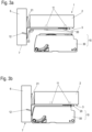
- FIG. 3a and 3b a first exemplary embodiment of an opening device 10 is shown, which is arranged in an upper or lower corner area of an insulating body 2 of a cooling device 1, which is otherwise not shown in any more detail here.
- the figures show a plan view of the corner area mentioned, whereby part of the insulating body 2 can be seen as well as a side wall of the furniture body 6.
- the opening device 10 is constructed in two parts with a mounting base 20 and a functional unit 30 that can be removed from the mounting base 20 .
- the mounting base 20 is first attached to the refrigerator 1 and the furniture body 6 in the corner area mentioned.
- screws 12 are screwed into the threaded inserts 11 of the cooling device 1 .
- the threaded inserts 11 are the fastening points for the door hinges already provided in the insulating body 2 of the cooling device 1, which are unused on the side opposite the inserted door hinges 9 and are available.
- the mounting base 20 is designed in the form of an L-shaped angle, which bears against the insulating body 2 with a longer leg. A shorter leg of the mounting base 20 is supported on the furniture body 6 . Provision can also be made for a fastening hole 23 to be provided in the mounting base 20 here, through which a self-tapping screw 12 can be screwed into the furniture body 6 .
- contacts 22 are arranged on the mounting base 20 and are connected to a connection cable 21 of the opening device 10 .
- the contacts 20 are arranged in a connector which is positioned in a corner area of the angled mounting base 20 .
- a gap remains between the insulating body 2 of the cooling device 1 and the side wall of the furniture body 6, through which the connecting cable 21 can be routed in order to connect it to a mains supply in the rear area of the cooling device 1 (not visible here), if necessary via a intermediate power supply.
- the connecting cable 21 can also include signal lines in order to connect the opening device to a sensor arrangement.
- An example of a sensor arrangement via which a manually initiated opening of the door arrangement of the Cooling device 1 is detected in order to trigger the function of the opening device 10 is in figure 9 shown.
- the functional unit 30 is attached to the screwed-on mounting base 20 .
- This attachment is advantageously carried out using a tool-free (locking) mechanism.
- By placing the functional unit 30 is over in the Figures 3a and 3b Not visible mating contacts of the functional unit 30 an electrical connection with the contacts 22 and thus the connection cable 21 made.
- the functional unit 30 can be easily replaced without the wiring of the connecting cable 21 having to be detached or reconnected, or without the connecting cable 21 having to be rerouted.
- the functional unit 30 can be replaced, for example, for repair, service and/or cleaning purposes. The replacement can be performed by the user or an unskilled service technician.
- FIG 4 shows in an isometric view the mounting base 20 of the embodiment of FIG Figures 3a and 3b more detailed.
- the mounting base 20 itself is constructed in two parts, with a soft intermediate layer 25 being provided, onto which an upper part of the mounting base 20 is placed.
- the upper part can be made of a hard plastic and the intermediate layer 25 can be made of a soft plastic, rubber or an elastomer, for example.
- a high stability of the mounting base 20 is achieved and at the same time good sound decoupling and/or sound absorption is achieved, so that vibrations generated by the opening device 10 are not transmitted to the cooling device 1 or the furniture body 6 as structure-borne noise.
- the mounting base 20 has mounting bores 23 which can be embodied as oblong holes in order to be able to move the mounting base 20 on the insulating body 2 and thus to be able to compensate for different gap dimensions between the cooling device 1 and the furniture body 6 .
- Another way of compensating for different gap dimensions is by inserting spacer plates.
- Fastening means 24 are also arranged on the mounting base 20 and serve to fasten the functional unit 30 to the mounting unit 20 . This can be latching elements and/or guides, possibly with undercuts.
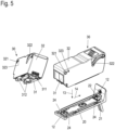
- figure 5 shows in its right part the opening device 10 with a separate mounting base 20 and functional unit 30 again in an isometric representation.
- the functional unit 30 is shown from a different perspective in the left-hand part of the figure.
- FIG. 5 That related to figure 4 already mentioned fastening the functional unit 30 on the mounting base 20 is in the figure 5 shown in more detail.
- Latching elements and guide webs with undercut areas are provided as fastening means 24 on the mounting base 20 in order to be able to slide the functional unit 30 onto the mounting base.
- the functional unit 30 has fastening means 312 that interact with these.
- the movement sequence provided for fastening is represented by two movement arrows 13,14.
- the functional unit 30 is first placed on the mounting base 20 and then pushed parallel to the longer leg of the mounting base 20 in the direction of the shorter leg, as indicated by the movement arrow 14 .
- Sections of the functional unit 30 engage behind corresponding sections of the guide webs of the mounting base 20 and at the same time mating contacts 311 of the functional unit 30 make contact with the contacts 22 of the mounting base 20.
- the functional unit 30 latches with its fastening means 312 the locking means of the mounting base 20, whereby the functional unit 30 is fixed in the pushed-on position. Additional fixing elements such as screws or a cotter pin can be provided.
- the figure 5 also shows details of the structure of the functional unit 30.
- This has a base body 31, the underside of which is pushed onto the mounting base 20 and on which the counter-contacts 311 mentioned are also arranged.
- the functional unit 30 also has an ejector element 32, which pivots open when the opening device 10 is functioning in order to open the door arrangement (cf. insulating door 4 and carcass door 8 in FIGS Figures 1a and 1b ) of the cooling device 1 to push open.
- the ejector element 32 is hood-shaped and slipped over the base body 31 . It is provided with a pivot bearing hole 321 with which it is mounted on the base body 31 .
- a guide curve 322 is formed on the ejection element 32, whose function in connection with the figures 7 and 8a-c will be explained in more detail.
- a further pivot bearing bore 323 is formed on the ejection element 32, the function of which is also explained below.
- a soft component can be arranged along the edge with which the ejector element 32 bears against the door arrangement, in particular it can be injection-molded on or molded on in a co-extrusion process.
- FIG 6 shows another embodiment of an opening device 10, which differs from the previously shown embodiment by the way the functional unit 30 is attached to the mounting base 20.
- the other function of the opening device 10 reference is made to the following statements on the first exemplary embodiment.
- the functional unit 30 is fastened to the mounting base 20 not by placing it on and moving it, but rather by hooking it in and pivoting it in. Hooking is symbolized by a movement arrow 15 and pivoting in by a movement arrow 16 .
- the functional unit 30 in this example has a rearwardly protruding projection as the fastening means 312 and the mounting base 20 has a receptacle as the fastening means 24 into which the projection is inserted. After insertion, the functional unit 30 is pivoted at the opposite end of the projection onto the mounting base 20 and locked there with locking means in the figure 6 are not visible.
- the contacts 22 and the counter-contacts 311 are also arranged differently and in particular have a different plug-in direction than in the first exemplary embodiment, which is adapted to pivoting in according to the movement arrow 16 .
- figure 7 12 shows the structure of the opening device 10 of the first embodiment in more detail.
- the Indian figure 7 visible internal structure of the functional unit 30 and the functionality achieved with it are analogous to the second exemplary embodiment according to FIG figure 6 implemented.
- the figure 7 shows the opening device 10 in the form of an isometric exploded drawing.
- the base body 31 of the functional unit 30 is inserted into the mounting base 20 .
- the ejection element 32 is in the form of a hood placed on the base body 31, bearing pins 313 being formed on the base body 31, which engage in the corresponding pivot bearing bore 321 of the ejector element 32 on both sides, so that the latter is pivotably attached to the base body 31.
- a semi-circular pivoting element 34 is rotatably mounted on the base body 31 on the side of the base body 31 opposite the bearing journal 313 .
- the pivoting element 34 is composed of two circular segments 341a, 341b, which are each placed on the base body 31 from one side, with a rotary axis 342 being rotatably mounted in a bearing bore 314.
- the assembled circle segments 341a, b are connected to each other in the axis of rotation 342 and in a connecting axis 343 arranged eccentrically to this.
- the connecting axis 343 protrudes outwards beyond the outer surfaces of the circular segments 341a, b, with rotatably mounted rollers 344 being placed on the connecting axes 343 in the protruding area. These rollers 344 engage in the previously mentioned guide curves 322 of the ejection element 32 . When the pivoting element 34 pivots, the rollers 344 move along the guide curve 322 and pivot the ejection element 32 out. This will be detailed in connection with the Figures 8a-8c described.
- a motor 315 is arranged in the base body 31, which acts on two drive gears 316 via a gear (not visible here), which in turn interact with a gear segment 345 of each circle segment 341a, b.
- the gear can be a worm gear, for example.
- the motor 315 can preferably be mounted elastically in order to ensure a drive that is as silent and vibration-free as possible.
- a weight can be attached to the motor 315 as a mass oscillator in order to further reduce vibration amplitudes.
- the gear segment 345 represents a section of an internal gear (also called a ring gear).
- an internal gear also called a ring gear.
- apron 33 arranged between the base body 31 and the ejection element, which can be pivoted with bearing pins 331 in the ejection element 32 is mounted in pivot bearing bores 323 .
- the pivot bearing 323 is adjacent to the pivot bearing 321 with which the ejection element 32 is mounted on the base body 31 .
- the apron 33 has the function of anti-pinch protection, as also in connection with those described below Figures 8a-8c is explained.
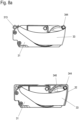
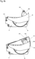
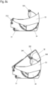
- the functional unit 30 is shown in three different functional positions, specifically in Figure 8a in a retracted position, in Figure 8b in a partially extended position and in Figure 8c a fully extended position of the ejection element 32.
- the figures each show the functional unit 30 in the upper part of the figure without the ejection element 32 in a side view and in the lower part of the figure with the ejection element 32 in a sectional view.
- the section is shown in a plane perpendicular to the pivot axis of the ejection element 32 just between the ejection element 32 and the skirt 33, so that the base body 31 and the skirt 33 in a side view and only the ejection element 32 is visible in section.
- the extension of the ejection element 32 is based on a rotation of the pivoting element 34, the rotational movement of which is converted into a pivoting movement of the ejection element 32 via the rollers 344.
- the guide curve 322 enables a larger pivoting angle of the ejection element 32 than would result solely from the rotary movement of the pivoting element 34 .
- the shape of the guide curve 322 also influences the angular dependency of the movement of the ejection element 32 as a function of the angle of rotation of the pivoting element 34. In this way, the most effective ejection movement can be achieved, which has a large ejection force at the beginning of the movement sequence, which is advantageous for avoiding magnetic locking forces of the door arrangement of the To overcome cooling device 1. This is followed by a higher speed burst to allow the door assembly to be burst open far enough. A progressive movement kinematics is generated in this way.
- the skirt 33 also performs a pivoting movement, but by a smaller deflection angle in such a way that a gap between the base body 31 and the ejection element 32 is closed at all times to prevent a finger, for example, being trapped when the ejection element 32 retracts again impede.
- a cam-like projection on the outside of the pivoting element 34 on the circular segments 341a, b 346 is formed, which presses on an upper or lower edge of the apron 33 and moves it accordingly.
- the shape of the projection 346 in conjunction with the shape of the edges of the skirt 33 determines the path of motion that the skirt 33 undergoes during movement of the pivot member 34 .
- a cam-like projection can also be formed on the ejection element 32 (pointing inwards in this case), which moves the apron 33 with it.
- a projection 346 can be provided for each direction of movement, so that the apron 33 is positively guided in both directions.
- the skirt 33 may have an inwardly pointing pin which moves along a guide groove machined into the outer surface of the respective circle segment 341a,b.
- the ejection element 32 can be extended or retracted by energizing the motor 315 with the appropriate polarity.
- At least one end stop switch can be provided, which is arranged inside the base body 31 and is actuated, for example, by an inwardly pointing cam on one of the circle segments 341a, b and stops the motor 315 in an end position. In principle, both end positions can be determined using switches.
- a circuit driving the motor 315 monitors the power consumption of the motor 315 and detects a mechanical end stop due to the increased power consumption and then stops the motor 315 .
- An electronic circuit for controlling the motor 315 and/or evaluating limit switches is preferably arranged in the functional unit 30, e.g. in the base body 31.
- a sensor can be arranged on the cooling device 1 or on the furniture body 6, which sensor detects a manually initiated opening process of the door arrangement, whereupon the ejection process of the opening device 10 is started.
- figure 9 shows an example of a sensor arrangement 40 suitable for this purpose, which is positioned on the furniture carcass 6 on the side of the door that is not hinged.
- the sensor arrangement 40 includes a pressure-dependent resistor 42 which is embedded in an elastic casing 41 .
- An adhesive film is preferably provided on the back of the casing, which allows for easy assembly. Alternatively or additionally, a screw fastening can take place.
- the shroud 41 has an actuator 43 at the appropriate location which protrudes slightly.
- a fixed housing can also be provided, in which the pressure-dependent resistor 42 is arranged and from which a movable actuator 43 protrudes.
- the pressure-dependent resistor 42 (FSR-force sensitive resistor) changes its resistance value when force is applied.
- the sensor arrangement 40 is positioned in such a way that the closed carcass door 8 presses on the pressure-dependent resistor 42 via the actuator 43 . If this pressure is absent when the carcass door 8 is moved, the resistance value of the pressure-dependent resistor 42 changes, which is detected by a corresponding monitoring circuit.
- the movement of the carcass door 8 can also be detected via a mechanical button, a reflected light barrier, a strain gauge, a piezoelectric element or a magnetic sensor in conjunction with a permanent magnet arranged in the carcass door 8 .
- a control device of the cooling device 1 for example a touch screen or via a network-enabled or SmartHome-enabled device, for example a smartphone or a voice input device.
Landscapes
- Engineering & Computer Science (AREA)
- Chemical & Material Sciences (AREA)
- Combustion & Propulsion (AREA)
- Physics & Mathematics (AREA)
- Mechanical Engineering (AREA)
- Thermal Sciences (AREA)
- General Engineering & Computer Science (AREA)
- Refrigerator Housings (AREA)
- Hinges (AREA)
Applications Claiming Priority (2)
| Application Number | Priority Date | Filing Date | Title |
|---|---|---|---|
| DE102019109650.2A DE102019109650A1 (de) | 2019-04-11 | 2019-04-11 | Öffnungsvorrichtung für ein Kühlgerät |
| PCT/EP2020/057656 WO2020207750A1 (de) | 2019-04-11 | 2020-03-19 | Öffnungsvorrichtung für ein kühlgerät |
Publications (2)
| Publication Number | Publication Date |
|---|---|
| EP3953552A1 EP3953552A1 (de) | 2022-02-16 |
| EP3953552B1 true EP3953552B1 (de) | 2023-09-06 |
Family
ID=69903184
Family Applications (1)
| Application Number | Title | Priority Date | Filing Date |
|---|---|---|---|
| EP20712950.3A Active EP3953552B1 (de) | 2019-04-11 | 2020-03-19 | Öffnungsvorrichtung für ein kühlgerät |
Country Status (9)
| Country | Link |
|---|---|
| US (1) | US12123641B2 (pl) |
| EP (1) | EP3953552B1 (pl) |
| CN (1) | CN113661301B (pl) |
| AU (1) | AU2020271922A1 (pl) |
| BR (1) | BR112021018290A2 (pl) |
| CA (1) | CA3133402A1 (pl) |
| DE (1) | DE102019109650A1 (pl) |
| PL (1) | PL3953552T3 (pl) |
| WO (1) | WO2020207750A1 (pl) |
Families Citing this family (4)
| Publication number | Priority date | Publication date | Assignee | Title |
|---|---|---|---|---|
| CN113464384A (zh) * | 2020-03-31 | 2021-10-01 | 北京金风科创风电设备有限公司 | 阻尼装置及风力发电机组 |
| US12492859B2 (en) * | 2022-05-04 | 2025-12-09 | Whirlpool Corporation | Refrigerator appliance subcomponent mounting system |
| US20240392972A1 (en) * | 2023-05-22 | 2024-11-28 | Therese Basse | Warming/Cooling Food Device |
| US20250369682A1 (en) * | 2024-05-31 | 2025-12-04 | SNWC, Inc. | Hinge for refrigerated cabinets |
Family Cites Families (25)
| Publication number | Priority date | Publication date | Assignee | Title |
|---|---|---|---|---|
| DE20115250U1 (de) * | 2001-07-06 | 2002-11-14 | Lautenschlaeger Mepla Werke | Dämpfungsvorrichtung |
| AT501778B1 (de) * | 2005-04-28 | 2009-11-15 | Blum Gmbh Julius | Ausstossvorrichtung für ein bewegbares möbelteil |
| AT503248B1 (de) * | 2006-03-03 | 2011-07-15 | Blum Gmbh Julius | Anordnung mit elektrischen antriebseinheiten für schubladen |
| US7351117B1 (en) * | 2006-11-06 | 2008-04-01 | Tyco Electronics Corporation | Electrical connector assembly having pre-staging and final staging contact configurations |
| US8299656B2 (en) * | 2008-03-12 | 2012-10-30 | Whirlpool Corporation | Feature module connection system |
| DE502008000178D1 (de) * | 2007-01-12 | 2009-12-31 | Hautau Gmbh | Endabdeckung für ein Gehäuse eines Stellantriebs und Verfahren der Anordnung des Gehäuses eines Stellantriebs |
| KR101576679B1 (ko) * | 2009-07-22 | 2015-12-10 | 엘지전자 주식회사 | 냉장고 도어 개방 장치 |
| KR20110022849A (ko) * | 2009-08-28 | 2011-03-08 | 삼성전자주식회사 | 냉장고 |
| KR101639435B1 (ko) * | 2009-10-13 | 2016-07-13 | 엘지전자 주식회사 | 냉장고 |
| US20120080991A1 (en) * | 2010-10-05 | 2012-04-05 | General Electric Company | Consumer appliance with finger guard |
| DE102013103819A1 (de) * | 2013-04-16 | 2014-10-16 | Miele & Cie. Kg | Kühlgerät |
| ITTO20130710A1 (it) * | 2013-09-02 | 2015-03-03 | Indesit Co Spa | Apparecchio di refrigerazione con passaggio per elemento tubolare flessibile tra armadio e porta |
| DE102014104418A1 (de) * | 2014-03-28 | 2015-10-01 | Küster Holding GmbH | Elektrisch schaltbare Kraftfahrzeugverglasung |
| DE102014107367B4 (de) * | 2014-05-26 | 2022-10-06 | Miele & Cie. Kg | Kühlgerät |
| DE102015214377A1 (de) * | 2015-07-29 | 2017-02-02 | Brose Fahrzeugteile Gmbh & Co. Kommanditgesellschaft, Bamberg | Vorrichtung zur Befestigung und elektrischen Kontaktierung einer Fahrzeug-Fensterscheibe |
| DE102016112164A1 (de) * | 2016-07-04 | 2018-01-04 | Hettich-Oni Gmbh & Co. Kg | Kühlgerät und Öffnungsvorrichtung für ein Kühlgerät |
| DE102016122594A1 (de) * | 2016-11-23 | 2018-05-24 | Hettich-Oni Gmbh & Co. Kg | Kühlgerät und Öffnungssystem für ein Kühlgerät |
| US20180149412A1 (en) * | 2016-11-28 | 2018-05-31 | Bsh Hausgeraete Gmbh | Home Appliance Device |
| US10544983B2 (en) * | 2017-01-03 | 2020-01-28 | Samsung Electronics Co., Ltd. | Refrigerator |
| KR102368377B1 (ko) * | 2017-03-29 | 2022-03-02 | 엘지전자 주식회사 | 냉장고 |
| KR101972785B1 (ko) * | 2017-03-29 | 2019-04-25 | 엘지전자 주식회사 | 냉장고 |
| KR102448499B1 (ko) * | 2017-06-02 | 2022-09-29 | 삼성전자주식회사 | 냉장고 및 냉장고 도어의 제어방법 |
| KR102494128B1 (ko) * | 2017-12-01 | 2023-02-01 | 엘지전자 주식회사 | 냉장고 |
| CN207598090U (zh) * | 2017-12-14 | 2018-07-10 | 江苏雷利电机股份有限公司 | 开启机构和包括所述开启机构的家用电器 |
| CN109209130A (zh) * | 2018-09-17 | 2019-01-15 | 珠海格力电器股份有限公司 | 一种自动开门装置及具有该自动开门装置的洗碗机 |
-
2019
- 2019-04-11 DE DE102019109650.2A patent/DE102019109650A1/de active Pending
-
2020
- 2020-03-19 EP EP20712950.3A patent/EP3953552B1/de active Active
- 2020-03-19 CA CA3133402A patent/CA3133402A1/en active Pending
- 2020-03-19 BR BR112021018290A patent/BR112021018290A2/pt not_active Application Discontinuation
- 2020-03-19 PL PL20712950.3T patent/PL3953552T3/pl unknown
- 2020-03-19 WO PCT/EP2020/057656 patent/WO2020207750A1/de not_active Ceased
- 2020-03-19 US US17/602,350 patent/US12123641B2/en active Active
- 2020-03-19 CN CN202080028037.9A patent/CN113661301B/zh active Active
- 2020-03-19 AU AU2020271922A patent/AU2020271922A1/en not_active Abandoned
Also Published As
| Publication number | Publication date |
|---|---|
| WO2020207750A1 (de) | 2020-10-15 |
| BR112021018290A2 (pt) | 2021-11-23 |
| PL3953552T3 (pl) | 2024-02-26 |
| DE102019109650A1 (de) | 2020-10-15 |
| EP3953552A1 (de) | 2022-02-16 |
| AU2020271922A1 (en) | 2021-10-07 |
| CN113661301B (zh) | 2023-06-02 |
| CA3133402A1 (en) | 2020-10-15 |
| CN113661301A (zh) | 2021-11-16 |
| US20220163254A1 (en) | 2022-05-26 |
| US12123641B2 (en) | 2024-10-22 |
Similar Documents
| Publication | Publication Date | Title |
|---|---|---|
| EP3953552B1 (de) | Öffnungsvorrichtung für ein kühlgerät | |
| RU2500870C2 (ru) | Предмет мебели с выталкивающим устройством для подвижных деталей мебели | |
| AT508072B1 (de) | Anordnung, umfassend ein Möbelscharnier und ein Antriebssystem | |
| DE69306516T2 (de) | Luftklappe | |
| CN109442857B (zh) | 左右开门结构及装载物品的箱柜 | |
| EP1548366A2 (de) | Türscharnier für eine Tür eines Haushaltsgeräts | |
| EP2020477A2 (de) | Automatisierung von Möbeln, Haushaltsgeräten und dergleichen | |
| EP3390932A1 (de) | Kühl- und/oder gefriergerät | |
| EP3479034A1 (de) | Kühlgerät und öffnungsvorrichtung für ein kühlgerät | |
| DE19945755A1 (de) | Klappenscharnieranordnung | |
| EP3348761B1 (de) | Vorrichtung zur schwenkbaren befestigung eines türflügels an einer türzarge | |
| CN217518466U (zh) | 一种顶门机构和电器设备 | |
| EP3359893B1 (de) | Abdeckteil für ein haushaltsgerät, tür für ein haushaltsgerät sowie haushaltsgerät | |
| DE102010020626A1 (de) | Kühl- und/oder Gefriergerät | |
| AT514944B1 (de) | Möbelantrieb | |
| WO2018095822A1 (de) | Kühlgerät und öffnungssystem für ein kühlgerät | |
| EP1555486A2 (de) | Ofentür | |
| DE102022204323A1 (de) | Türöffnungsvorrichtung, Haushaltsgerät sowie Verfahren zum Unterstützen des Öffnens einer Tür eines Haushaltsgeräts | |
| RU2799224C2 (ru) | Открывающее устройство для охлаждающего устройства | |
| CN223023849U (zh) | 一种便于安装电气元件的低压开关柜 | |
| CN218605759U (zh) | 一种具有斜开功能的橱柜抽屉门板装配结构 | |
| DE3817075A1 (de) | Tuer-sicherheitsschalter fuer ein haushaltgeraet | |
| KR200341462Y1 (ko) | 공기조화기의 오토셔터 개폐장치 | |
| DE102022204325A1 (de) | Türöffnungsvorrichtung, Haushaltsgerät sowie Verfahren zum Bewirken des Öffnens einer Tür eines Haushaltsgeräts | |
| DE9203517U1 (de) | Torantrieb, insbesondere für ein Garagentor |
Legal Events
| Date | Code | Title | Description |
|---|---|---|---|
| STAA | Information on the status of an ep patent application or granted ep patent |
Free format text: STATUS: UNKNOWN |
|
| STAA | Information on the status of an ep patent application or granted ep patent |
Free format text: STATUS: THE INTERNATIONAL PUBLICATION HAS BEEN MADE |
|
| PUAI | Public reference made under article 153(3) epc to a published international application that has entered the european phase |
Free format text: ORIGINAL CODE: 0009012 |
|
| STAA | Information on the status of an ep patent application or granted ep patent |
Free format text: STATUS: REQUEST FOR EXAMINATION WAS MADE |
|
| 17P | Request for examination filed |
Effective date: 20211109 |
|
| AK | Designated contracting states |
Kind code of ref document: A1 Designated state(s): AL AT BE BG CH CY CZ DE DK EE ES FI FR GB GR HR HU IE IS IT LI LT LU LV MC MK MT NL NO PL PT RO RS SE SI SK SM TR |
|
| DAV | Request for validation of the european patent (deleted) | ||
| DAX | Request for extension of the european patent (deleted) | ||
| STAA | Information on the status of an ep patent application or granted ep patent |
Free format text: STATUS: EXAMINATION IS IN PROGRESS |
|
| 17Q | First examination report despatched |
Effective date: 20220926 |
|
| GRAP | Despatch of communication of intention to grant a patent |
Free format text: ORIGINAL CODE: EPIDOSNIGR1 |
|
| STAA | Information on the status of an ep patent application or granted ep patent |
Free format text: STATUS: GRANT OF PATENT IS INTENDED |
|
| INTG | Intention to grant announced |
Effective date: 20230405 |
|
| GRAS | Grant fee paid |
Free format text: ORIGINAL CODE: EPIDOSNIGR3 |
|
| GRAA | (expected) grant |
Free format text: ORIGINAL CODE: 0009210 |
|
| STAA | Information on the status of an ep patent application or granted ep patent |
Free format text: STATUS: THE PATENT HAS BEEN GRANTED |
|
| P01 | Opt-out of the competence of the unified patent court (upc) registered |
Effective date: 20230702 |
|
| AK | Designated contracting states |
Kind code of ref document: B1 Designated state(s): AL AT BE BG CH CY CZ DE DK EE ES FI FR GB GR HR HU IE IS IT LI LT LU LV MC MK MT NL NO PL PT RO RS SE SI SK SM TR |
|
| REG | Reference to a national code |
Ref country code: GB Ref legal event code: FG4D Free format text: NOT ENGLISH |
|
| REG | Reference to a national code |
Ref country code: CH Ref legal event code: EP |
|
| REG | Reference to a national code |
Ref country code: IE Ref legal event code: FG4D Free format text: LANGUAGE OF EP DOCUMENT: GERMAN |
|
| REG | Reference to a national code |
Ref country code: DE Ref legal event code: R096 Ref document number: 502020005128 Country of ref document: DE |
|
| REG | Reference to a national code |
Ref country code: LT Ref legal event code: MG9D |
|
| REG | Reference to a national code |
Ref country code: NL Ref legal event code: MP Effective date: 20230906 |
|
| PG25 | Lapsed in a contracting state [announced via postgrant information from national office to epo] |
Ref country code: GR Free format text: LAPSE BECAUSE OF FAILURE TO SUBMIT A TRANSLATION OF THE DESCRIPTION OR TO PAY THE FEE WITHIN THE PRESCRIBED TIME-LIMIT Effective date: 20231207 |
|
| PG25 | Lapsed in a contracting state [announced via postgrant information from national office to epo] |
Ref country code: SE Free format text: LAPSE BECAUSE OF FAILURE TO SUBMIT A TRANSLATION OF THE DESCRIPTION OR TO PAY THE FEE WITHIN THE PRESCRIBED TIME-LIMIT Effective date: 20230906 Ref country code: RS Free format text: LAPSE BECAUSE OF FAILURE TO SUBMIT A TRANSLATION OF THE DESCRIPTION OR TO PAY THE FEE WITHIN THE PRESCRIBED TIME-LIMIT Effective date: 20230906 Ref country code: NO Free format text: LAPSE BECAUSE OF FAILURE TO SUBMIT A TRANSLATION OF THE DESCRIPTION OR TO PAY THE FEE WITHIN THE PRESCRIBED TIME-LIMIT Effective date: 20231206 Ref country code: LV Free format text: LAPSE BECAUSE OF FAILURE TO SUBMIT A TRANSLATION OF THE DESCRIPTION OR TO PAY THE FEE WITHIN THE PRESCRIBED TIME-LIMIT Effective date: 20230906 Ref country code: LT Free format text: LAPSE BECAUSE OF FAILURE TO SUBMIT A TRANSLATION OF THE DESCRIPTION OR TO PAY THE FEE WITHIN THE PRESCRIBED TIME-LIMIT Effective date: 20230906 Ref country code: HR Free format text: LAPSE BECAUSE OF FAILURE TO SUBMIT A TRANSLATION OF THE DESCRIPTION OR TO PAY THE FEE WITHIN THE PRESCRIBED TIME-LIMIT Effective date: 20230906 Ref country code: GR Free format text: LAPSE BECAUSE OF FAILURE TO SUBMIT A TRANSLATION OF THE DESCRIPTION OR TO PAY THE FEE WITHIN THE PRESCRIBED TIME-LIMIT Effective date: 20231207 Ref country code: FI Free format text: LAPSE BECAUSE OF FAILURE TO SUBMIT A TRANSLATION OF THE DESCRIPTION OR TO PAY THE FEE WITHIN THE PRESCRIBED TIME-LIMIT Effective date: 20230906 |
|
| PG25 | Lapsed in a contracting state [announced via postgrant information from national office to epo] |
Ref country code: NL Free format text: LAPSE BECAUSE OF FAILURE TO SUBMIT A TRANSLATION OF THE DESCRIPTION OR TO PAY THE FEE WITHIN THE PRESCRIBED TIME-LIMIT Effective date: 20230906 |
|
| PG25 | Lapsed in a contracting state [announced via postgrant information from national office to epo] |
Ref country code: IS Free format text: LAPSE BECAUSE OF FAILURE TO SUBMIT A TRANSLATION OF THE DESCRIPTION OR TO PAY THE FEE WITHIN THE PRESCRIBED TIME-LIMIT Effective date: 20240106 |
|
| PG25 | Lapsed in a contracting state [announced via postgrant information from national office to epo] |
Ref country code: ES Free format text: LAPSE BECAUSE OF FAILURE TO SUBMIT A TRANSLATION OF THE DESCRIPTION OR TO PAY THE FEE WITHIN THE PRESCRIBED TIME-LIMIT Effective date: 20230906 |
|
| PG25 | Lapsed in a contracting state [announced via postgrant information from national office to epo] |
Ref country code: SM Free format text: LAPSE BECAUSE OF FAILURE TO SUBMIT A TRANSLATION OF THE DESCRIPTION OR TO PAY THE FEE WITHIN THE PRESCRIBED TIME-LIMIT Effective date: 20230906 Ref country code: RO Free format text: LAPSE BECAUSE OF FAILURE TO SUBMIT A TRANSLATION OF THE DESCRIPTION OR TO PAY THE FEE WITHIN THE PRESCRIBED TIME-LIMIT Effective date: 20230906 Ref country code: IS Free format text: LAPSE BECAUSE OF FAILURE TO SUBMIT A TRANSLATION OF THE DESCRIPTION OR TO PAY THE FEE WITHIN THE PRESCRIBED TIME-LIMIT Effective date: 20240106 Ref country code: ES Free format text: LAPSE BECAUSE OF FAILURE TO SUBMIT A TRANSLATION OF THE DESCRIPTION OR TO PAY THE FEE WITHIN THE PRESCRIBED TIME-LIMIT Effective date: 20230906 Ref country code: EE Free format text: LAPSE BECAUSE OF FAILURE TO SUBMIT A TRANSLATION OF THE DESCRIPTION OR TO PAY THE FEE WITHIN THE PRESCRIBED TIME-LIMIT Effective date: 20230906 Ref country code: CZ Free format text: LAPSE BECAUSE OF FAILURE TO SUBMIT A TRANSLATION OF THE DESCRIPTION OR TO PAY THE FEE WITHIN THE PRESCRIBED TIME-LIMIT Effective date: 20230906 Ref country code: SK Free format text: LAPSE BECAUSE OF FAILURE TO SUBMIT A TRANSLATION OF THE DESCRIPTION OR TO PAY THE FEE WITHIN THE PRESCRIBED TIME-LIMIT Effective date: 20230906 Ref country code: PT Free format text: LAPSE BECAUSE OF FAILURE TO SUBMIT A TRANSLATION OF THE DESCRIPTION OR TO PAY THE FEE WITHIN THE PRESCRIBED TIME-LIMIT Effective date: 20240108 |
|
| REG | Reference to a national code |
Ref country code: DE Ref legal event code: R097 Ref document number: 502020005128 Country of ref document: DE |
|
| PG25 | Lapsed in a contracting state [announced via postgrant information from national office to epo] |
Ref country code: DK Free format text: LAPSE BECAUSE OF FAILURE TO SUBMIT A TRANSLATION OF THE DESCRIPTION OR TO PAY THE FEE WITHIN THE PRESCRIBED TIME-LIMIT Effective date: 20230906 |
|
| PLBE | No opposition filed within time limit |
Free format text: ORIGINAL CODE: 0009261 |
|
| STAA | Information on the status of an ep patent application or granted ep patent |
Free format text: STATUS: NO OPPOSITION FILED WITHIN TIME LIMIT |
|
| PG25 | Lapsed in a contracting state [announced via postgrant information from national office to epo] |
Ref country code: DK Free format text: LAPSE BECAUSE OF FAILURE TO SUBMIT A TRANSLATION OF THE DESCRIPTION OR TO PAY THE FEE WITHIN THE PRESCRIBED TIME-LIMIT Effective date: 20230906 Ref country code: SI Free format text: LAPSE BECAUSE OF FAILURE TO SUBMIT A TRANSLATION OF THE DESCRIPTION OR TO PAY THE FEE WITHIN THE PRESCRIBED TIME-LIMIT Effective date: 20230906 |
|
| 26N | No opposition filed |
Effective date: 20240607 |
|
| REG | Reference to a national code |
Ref country code: CH Ref legal event code: PL |
|
| PG25 | Lapsed in a contracting state [announced via postgrant information from national office to epo] |
Ref country code: BG Free format text: LAPSE BECAUSE OF FAILURE TO SUBMIT A TRANSLATION OF THE DESCRIPTION OR TO PAY THE FEE WITHIN THE PRESCRIBED TIME-LIMIT Effective date: 20230906 |
|
| PG25 | Lapsed in a contracting state [announced via postgrant information from national office to epo] |
Ref country code: LU Free format text: LAPSE BECAUSE OF NON-PAYMENT OF DUE FEES Effective date: 20240319 |
|
| PG25 | Lapsed in a contracting state [announced via postgrant information from national office to epo] |
Ref country code: MC Free format text: LAPSE BECAUSE OF FAILURE TO SUBMIT A TRANSLATION OF THE DESCRIPTION OR TO PAY THE FEE WITHIN THE PRESCRIBED TIME-LIMIT Effective date: 20230906 |
|
| PG25 | Lapsed in a contracting state [announced via postgrant information from national office to epo] |
Ref country code: MC Free format text: LAPSE BECAUSE OF FAILURE TO SUBMIT A TRANSLATION OF THE DESCRIPTION OR TO PAY THE FEE WITHIN THE PRESCRIBED TIME-LIMIT Effective date: 20230906 Ref country code: LU Free format text: LAPSE BECAUSE OF NON-PAYMENT OF DUE FEES Effective date: 20240319 Ref country code: BG Free format text: LAPSE BECAUSE OF FAILURE TO SUBMIT A TRANSLATION OF THE DESCRIPTION OR TO PAY THE FEE WITHIN THE PRESCRIBED TIME-LIMIT Effective date: 20230906 |
|
| REG | Reference to a national code |
Ref country code: BE Ref legal event code: MM Effective date: 20240331 |
|
| PG25 | Lapsed in a contracting state [announced via postgrant information from national office to epo] |
Ref country code: BE Free format text: LAPSE BECAUSE OF NON-PAYMENT OF DUE FEES Effective date: 20240331 |
|
| PG25 | Lapsed in a contracting state [announced via postgrant information from national office to epo] |
Ref country code: FR Free format text: LAPSE BECAUSE OF NON-PAYMENT OF DUE FEES Effective date: 20240331 |
|
| PG25 | Lapsed in a contracting state [announced via postgrant information from national office to epo] |
Ref country code: IE Free format text: LAPSE BECAUSE OF NON-PAYMENT OF DUE FEES Effective date: 20240319 |
|
| PG25 | Lapsed in a contracting state [announced via postgrant information from national office to epo] |
Ref country code: IE Free format text: LAPSE BECAUSE OF NON-PAYMENT OF DUE FEES Effective date: 20240319 Ref country code: FR Free format text: LAPSE BECAUSE OF NON-PAYMENT OF DUE FEES Effective date: 20240331 Ref country code: BE Free format text: LAPSE BECAUSE OF NON-PAYMENT OF DUE FEES Effective date: 20240331 Ref country code: CH Free format text: LAPSE BECAUSE OF NON-PAYMENT OF DUE FEES Effective date: 20240331 |
|
| PGFP | Annual fee paid to national office [announced via postgrant information from national office to epo] |
Ref country code: PL Payment date: 20250310 Year of fee payment: 6 |
|
| PGFP | Annual fee paid to national office [announced via postgrant information from national office to epo] |
Ref country code: IT Payment date: 20250331 Year of fee payment: 6 |
|
| PG25 | Lapsed in a contracting state [announced via postgrant information from national office to epo] |
Ref country code: CY Free format text: LAPSE BECAUSE OF FAILURE TO SUBMIT A TRANSLATION OF THE DESCRIPTION OR TO PAY THE FEE WITHIN THE PRESCRIBED TIME-LIMIT; INVALID AB INITIO Effective date: 20200319 |
|
| PG25 | Lapsed in a contracting state [announced via postgrant information from national office to epo] |
Ref country code: HU Free format text: LAPSE BECAUSE OF FAILURE TO SUBMIT A TRANSLATION OF THE DESCRIPTION OR TO PAY THE FEE WITHIN THE PRESCRIBED TIME-LIMIT; INVALID AB INITIO Effective date: 20200319 |
|
| PGFP | Annual fee paid to national office [announced via postgrant information from national office to epo] |
Ref country code: GB Payment date: 20260324 Year of fee payment: 7 |
|
| PGFP | Annual fee paid to national office [announced via postgrant information from national office to epo] |
Ref country code: DE Payment date: 20260320 Year of fee payment: 7 |
|
| PGFP | Annual fee paid to national office [announced via postgrant information from national office to epo] |
Ref country code: AT Payment date: 20260319 Year of fee payment: 7 |
|
| PGFP | Annual fee paid to national office [announced via postgrant information from national office to epo] |
Ref country code: TR Payment date: 20260316 Year of fee payment: 7 |