EP3953552B1 - Opening device for a cooling device - Google Patents
Opening device for a cooling device Download PDFInfo
- Publication number
- EP3953552B1 EP3953552B1 EP20712950.3A EP20712950A EP3953552B1 EP 3953552 B1 EP3953552 B1 EP 3953552B1 EP 20712950 A EP20712950 A EP 20712950A EP 3953552 B1 EP3953552 B1 EP 3953552B1
- Authority
- EP
- European Patent Office
- Prior art keywords
- opening device
- mounting base
- functional unit
- door
- ejection element
- Prior art date
- Legal status (The legal status is an assumption and is not a legal conclusion. Google has not performed a legal analysis and makes no representation as to the accuracy of the status listed.)
- Active
Links
- 238000001816 cooling Methods 0.000 title claims description 41
- 230000033001 locomotion Effects 0.000 claims description 36
- 230000013011 mating Effects 0.000 claims description 5
- 238000013016 damping Methods 0.000 claims description 2
- 238000009434 installation Methods 0.000 description 10
- 230000001419 dependent effect Effects 0.000 description 8
- 238000005057 refrigeration Methods 0.000 description 5
- 230000007246 mechanism Effects 0.000 description 4
- 230000008439 repair process Effects 0.000 description 4
- 238000013461 design Methods 0.000 description 3
- 238000000034 method Methods 0.000 description 3
- 230000008569 process Effects 0.000 description 3
- 238000004140 cleaning Methods 0.000 description 2
- 229920001971 elastomer Polymers 0.000 description 2
- 230000002093 peripheral effect Effects 0.000 description 2
- 238000010521 absorption reaction Methods 0.000 description 1
- 239000002313 adhesive film Substances 0.000 description 1
- 230000004888 barrier function Effects 0.000 description 1
- 230000005540 biological transmission Effects 0.000 description 1
- 230000008859 change Effects 0.000 description 1
- 230000008878 coupling Effects 0.000 description 1
- 238000010168 coupling process Methods 0.000 description 1
- 238000005859 coupling reaction Methods 0.000 description 1
- 238000011161 development Methods 0.000 description 1
- 230000018109 developmental process Effects 0.000 description 1
- 238000010586 diagram Methods 0.000 description 1
- 239000000806 elastomer Substances 0.000 description 1
- 238000001125 extrusion Methods 0.000 description 1
- 238000003780 insertion Methods 0.000 description 1
- 230000037431 insertion Effects 0.000 description 1
- 238000009413 insulation Methods 0.000 description 1
- 239000012212 insulator Substances 0.000 description 1
- 238000012544 monitoring process Methods 0.000 description 1
- 230000000750 progressive effect Effects 0.000 description 1
- 238000010079 rubber tapping Methods 0.000 description 1
- 238000007493 shaping process Methods 0.000 description 1
- 125000006850 spacer group Chemical group 0.000 description 1
- 230000001960 triggered effect Effects 0.000 description 1
Images


Classifications
-
- F—MECHANICAL ENGINEERING; LIGHTING; HEATING; WEAPONS; BLASTING
- F25—REFRIGERATION OR COOLING; COMBINED HEATING AND REFRIGERATION SYSTEMS; HEAT PUMP SYSTEMS; MANUFACTURE OR STORAGE OF ICE; LIQUEFACTION SOLIDIFICATION OF GASES
- F25D—REFRIGERATORS; COLD ROOMS; ICE-BOXES; COOLING OR FREEZING APPARATUS NOT OTHERWISE PROVIDED FOR
- F25D23/00—General constructional features
- F25D23/10—Arrangements for mounting in particular locations, e.g. for built-in type, for corner type
-
- E—FIXED CONSTRUCTIONS
- E05—LOCKS; KEYS; WINDOW OR DOOR FITTINGS; SAFES
- E05F—DEVICES FOR MOVING WINGS INTO OPEN OR CLOSED POSITION; CHECKS FOR WINGS; WING FITTINGS NOT OTHERWISE PROVIDED FOR, CONCERNED WITH THE FUNCTIONING OF THE WING
- E05F15/00—Power-operated mechanisms for wings
- E05F15/60—Power-operated mechanisms for wings using electrical actuators
- E05F15/603—Power-operated mechanisms for wings using electrical actuators using rotary electromotors
- E05F15/611—Power-operated mechanisms for wings using electrical actuators using rotary electromotors for swinging wings
- E05F15/616—Power-operated mechanisms for wings using electrical actuators using rotary electromotors for swinging wings operated by push-pull mechanisms
-
- F—MECHANICAL ENGINEERING; LIGHTING; HEATING; WEAPONS; BLASTING
- F25—REFRIGERATION OR COOLING; COMBINED HEATING AND REFRIGERATION SYSTEMS; HEAT PUMP SYSTEMS; MANUFACTURE OR STORAGE OF ICE; LIQUEFACTION SOLIDIFICATION OF GASES
- F25D—REFRIGERATORS; COLD ROOMS; ICE-BOXES; COOLING OR FREEZING APPARATUS NOT OTHERWISE PROVIDED FOR
- F25D23/00—General constructional features
- F25D23/02—Doors; Covers
- F25D23/028—Details
-
- E—FIXED CONSTRUCTIONS
- E05—LOCKS; KEYS; WINDOW OR DOOR FITTINGS; SAFES
- E05Y—INDEXING SCHEME RELATING TO HINGES OR OTHER SUSPENSION DEVICES FOR DOORS, WINDOWS OR WINGS AND DEVICES FOR MOVING WINGS INTO OPEN OR CLOSED POSITION, CHECKS FOR WINGS AND WING FITTINGS NOT OTHERWISE PROVIDED FOR, CONCERNED WITH THE FUNCTIONING OF THE WING
- E05Y2201/00—Constructional elements; Accessories therefore
- E05Y2201/40—Motors; Magnets; Springs; Weights; Accessories therefore
- E05Y2201/404—Motors; Magnets; Springs; Weights; Accessories therefore characterised by the function
- E05Y2201/422—Motors; Magnets; Springs; Weights; Accessories therefore characterised by the function for opening
- E05Y2201/426—Motors; Magnets; Springs; Weights; Accessories therefore characterised by the function for opening for the initial opening movement
-
- E—FIXED CONSTRUCTIONS
- E05—LOCKS; KEYS; WINDOW OR DOOR FITTINGS; SAFES
- E05Y—INDEXING SCHEME RELATING TO HINGES OR OTHER SUSPENSION DEVICES FOR DOORS, WINDOWS OR WINGS AND DEVICES FOR MOVING WINGS INTO OPEN OR CLOSED POSITION, CHECKS FOR WINGS AND WING FITTINGS NOT OTHERWISE PROVIDED FOR, CONCERNED WITH THE FUNCTIONING OF THE WING
- E05Y2201/00—Constructional elements; Accessories therefore
- E05Y2201/60—Suspension or transmission members; Accessories therefore
- E05Y2201/622—Suspension or transmission members elements
- E05Y2201/624—Arms
-
- E—FIXED CONSTRUCTIONS
- E05—LOCKS; KEYS; WINDOW OR DOOR FITTINGS; SAFES
- E05Y—INDEXING SCHEME RELATING TO HINGES OR OTHER SUSPENSION DEVICES FOR DOORS, WINDOWS OR WINGS AND DEVICES FOR MOVING WINGS INTO OPEN OR CLOSED POSITION, CHECKS FOR WINGS AND WING FITTINGS NOT OTHERWISE PROVIDED FOR, CONCERNED WITH THE FUNCTIONING OF THE WING
- E05Y2400/00—Electronic control; Power supply; Power or signal transmission; User interfaces
- E05Y2400/60—Power supply; Power or signal transmission
- E05Y2400/65—Power or signal transmission
-
- E—FIXED CONSTRUCTIONS
- E05—LOCKS; KEYS; WINDOW OR DOOR FITTINGS; SAFES
- E05Y—INDEXING SCHEME RELATING TO HINGES OR OTHER SUSPENSION DEVICES FOR DOORS, WINDOWS OR WINGS AND DEVICES FOR MOVING WINGS INTO OPEN OR CLOSED POSITION, CHECKS FOR WINGS AND WING FITTINGS NOT OTHERWISE PROVIDED FOR, CONCERNED WITH THE FUNCTIONING OF THE WING
- E05Y2600/00—Mounting or coupling arrangements for elements provided for in this subclass
- E05Y2600/50—Mounting methods; Positioning
- E05Y2600/52—Toolless
- E05Y2600/528—Hooking, e.g. using bayonets; Locking
-
- E—FIXED CONSTRUCTIONS
- E05—LOCKS; KEYS; WINDOW OR DOOR FITTINGS; SAFES
- E05Y—INDEXING SCHEME RELATING TO HINGES OR OTHER SUSPENSION DEVICES FOR DOORS, WINDOWS OR WINGS AND DEVICES FOR MOVING WINGS INTO OPEN OR CLOSED POSITION, CHECKS FOR WINGS AND WING FITTINGS NOT OTHERWISE PROVIDED FOR, CONCERNED WITH THE FUNCTIONING OF THE WING
- E05Y2600/00—Mounting or coupling arrangements for elements provided for in this subclass
- E05Y2600/60—Mounting or coupling members; Accessories therefore
- E05Y2600/626—Plates or brackets
-
- E—FIXED CONSTRUCTIONS
- E05—LOCKS; KEYS; WINDOW OR DOOR FITTINGS; SAFES
- E05Y—INDEXING SCHEME RELATING TO HINGES OR OTHER SUSPENSION DEVICES FOR DOORS, WINDOWS OR WINGS AND DEVICES FOR MOVING WINGS INTO OPEN OR CLOSED POSITION, CHECKS FOR WINGS AND WING FITTINGS NOT OTHERWISE PROVIDED FOR, CONCERNED WITH THE FUNCTIONING OF THE WING
- E05Y2900/00—Application of doors, windows, wings or fittings thereof
- E05Y2900/30—Application of doors, windows, wings or fittings thereof for domestic appliances
- E05Y2900/31—Application of doors, windows, wings or fittings thereof for domestic appliances for refrigerators
-
- F—MECHANICAL ENGINEERING; LIGHTING; HEATING; WEAPONS; BLASTING
- F25—REFRIGERATION OR COOLING; COMBINED HEATING AND REFRIGERATION SYSTEMS; HEAT PUMP SYSTEMS; MANUFACTURE OR STORAGE OF ICE; LIQUEFACTION SOLIDIFICATION OF GASES
- F25D—REFRIGERATORS; COLD ROOMS; ICE-BOXES; COOLING OR FREEZING APPARATUS NOT OTHERWISE PROVIDED FOR
- F25D2400/00—General features of, or devices for refrigerators, cold rooms, ice-boxes, or for cooling or freezing apparatus not covered by any other subclass
- F25D2400/40—Refrigerating devices characterised by electrical wiring
Definitions
- the invention relates to an opening device for a refrigeration appliance with a door arrangement, the opening device having a mounting base which can be mounted on fastening devices provided for a door hinge of the refrigeration appliance, and having a functional unit with an ejection element which can be extended in an electrically controlled manner.
- Common household refrigerators such as refrigerators or freezers, generally have a pivoting door that is sealed off from the body of the refrigerator with a peripheral seal.
- the circumferential seal is typically designed as a magnetic seal that applies locking forces between the door and the body.
- the door hinges can be equipped with a self-closing function that provides additional locking forces.
- the opening devices mentioned at the outset are known, in which an ejection element can be extended from a housing in an electrically driven manner, with which the door of the cooling device is pushed open at least far enough that the door can be easily reached from behind and then opened completely manually .
- Such an opening device is, for example, from the publication EP 2 292 995 B1 known.
- the opening device described there is mounted on an upper side of the refrigerator and presses with its ejection element against an upper, projecting edge of the door of the refrigerator.
- the opening device has a coil in which an armature is slidably mounted.
- the armature is held in a rest position by a spring element and moves out when the coil is energized.
- the disengaging armature acts on the door via a lever mechanism in order to open it at least a little.
- An arrangement of the opening device on top of the cooling device is often undesirable for design reasons.
- the top of the cooling unit can only be used as a storage space to a limited extent.
- a cooling device with an opening device positioned in this way is only suitable to a limited extent for installation in a furniture body, since the opening device, which protrudes upwards beyond the insulating body of the cooling device, would result in an only partially closed gap between the cooling device and a top plate or a shelf of the furniture body .
- a refrigerator having an opening and/or closing device inserted in a pocket formed on the front side of an insulating body.
- An electrical socket is arranged in the pocket, into which a plug arranged on the opening and/or closing device engages.
- the pamphlet WO 2018/007240 A1 shows an opening device of the type mentioned. This is characterized in that it can be mounted on provided fastening devices for a door hinge of the refrigerator using a mounting bracket on a front end face of an insulating body of the refrigerator. Furthermore, the opening device is designed in such a way that its ejection element acts on an area of the door arrangement which is outside of the seal.
- the opening device thus advantageously uses the installation space for the door hinges that is provided as standard in the refrigerator and also makes use of the fastening devices for the door hinges that have already been prepared in this context. When the opening device is installed in this installation space, a connection cable must be routed from this installation space between the cooling device and a piece of furniture in which the cooling device is installed. This connection diagram makes it difficult to replace the opening device in the event of service or repairs.
- An opening device is characterized in that the mounting base has contacts and the functional unit has counter-contacts, the contacts and the counter-contacts contacting one another when the functional unit is fastened to the mounting base to supply power to the functional unit.
- the functional unit can be easily replaced without the wiring of a connecting cable having to be disconnected or reconnected, or without a connecting cable having to be rerouted .
- the functional unit can be replaced, for example, for repair, service and/or cleaning purposes. The replacement can be performed by the user or an unskilled service technician.
- the contacts of the mounting base are connected to a connection cable that has power supply lines and, if necessary, signal lines.
- the mounting base and the functional unit have fastening means which engage in one another.
- the fastening means are preferably designed in such a way that the functional unit can be fastened to the mounting base without the use of tools.
- the fastening means include, for example, locking means, guide webs, hooks, eyes and/or undercuts.
- the mounting base In order to fasten the mounting base, it has mounting bores for connection to the cooling device and preferably also for connection to a furniture body into which the cooling device is accommodated (slide in).
- the mounting base can be L-shaped, for example.
- the preferred installation location for the opening device is the standard installation space provided for the door hinges in the refrigerator. It is then particularly advantageous to also use the fastening devices for the door hinges, which have already been prepared in this connection, for fastening the mounting base.
- an opening device according to the invention can be easily retrofitted for a large number of cooling devices that are already available on the market.
- no other space that can be used, for example on a top side of the cooling device is occupied.
- an intervention in the insulating body, which goes beyond the fastening devices of the door hinges that are present anyway, is not necessary.
- a minimum distance between the furniture body and the cooling device for the passage of the connecting cable is defined via the mounting base.
- the housing of the opening device advantageously has a depth of less than 60 millimeters (mm), preferably less than 47 mm or preferably between 38 and 47 mm.
- the ejection element has a maximum stroke of 40 mm to 80 mm.
- the door arrangement can be opened far enough for the locking force of the (magnetic) seal and the negative pressure in the interior of the refrigerator to be overcome.
- the door arrangement can then be easily reached from behind to open it fully.
- the door arrangement is preferably only opened so far by the opening device that it is still in the self-closing area of the door hinges if they are equipped with a self-closing mechanism. If the door arrangement is not opened manually, it then closes automatically after the ejection element is retracted.
- the ejection element is pivotably mounted on a base body and, in a non-pivoted position, surrounds the base body in the form of a hood on at least four sides.
- the opening device preferably has a pivoting element which is pivotably mounted on the base body and has at least one internal gear wheel segment which is coupled to an electric motor via a drive gear wheel and can be pivoted by the motor relative to the base body.
- the pivoting element moves the ejection element with it, preferably via at least one roller which is arranged eccentrically on the pivoting element and moves along a guide curve in the ejection element.
- the guide curve enables a larger pivoting angle of the ejection element than would result solely from the rotary movement of the pivoting element.
- the angle dependency of the movement of the ejection element can also be influenced as a function of the angle of rotation of the pivoting element by shaping the guide curve. In this way, an ejection movement that is as effective as possible can be achieved, which at the beginning of the movement sequence has a large ejection force, which is advantageous in order to overcome magnetic locking forces of the door arrangement of the refrigerator. This is followed by a higher speed burst to allow the door assembly to be burst open far enough.
- the opening device has an apron which is pivotably mounted on the base body or the ejection element and which extends between the base body and the ejection element as protection against pinching.
- the apron is preferably also moved in a forcibly guided manner in at least one movement direction by the pivoting element and/or the ejection element. A forced movement of the apron ensures that it is always in a suitable position in which it prevents a finger, for example, from getting caught when the ejection element is retracted again.
- the electric motor is coupled to the drive gear wheel via a worm gear.
- a suitable transmission ratio can be achieved in a space-saving manner with just one gear stage.
- the electric motor is preferably fastened in or on the base body in a vibration-damping manner. In this way, operation of the opening device is as silent as possible.
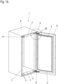
- a cooling device 1 is shown in an isometric representation.
- the refrigerator 1 can be, for example, a refrigerator or a freezer for use in the home or for commercial use.
- the cooling device 1 has a heat-insulated body, referred to below as the insulating body 2, whose interior space and front end face 3 can be seen in the figures shown.
- the insulating body 2 is assigned a thermally insulated door, referred to below as the insulating door 4, which has a peripheral seal 5, usually a magnetic seal.
- the seal 5 lies circumferentially on the front face 3 of the insulating body 2 and thus hermetically seals the interior of the insulating body 2 .
- the insulating body 2 is built into a furniture body 6, to which a body door 8 is assigned, which rests against a front face 7 of the furniture body 6 in the closed state.
- the carcass door 8 and the insulating door 4 form a unit that is firmly connected to one another.
- the body door 8 can also be connected to the insulating door as a so-called trailing door.
- the corpus door 8 protrudes outwards over the insulating door 4 on all sides.
- the insulating door 4 is pivotably connected to the insulating body 2 of the cooling device 1 via door hinges 9 .
- the actual joint mechanism of the respective door hinge 9 is arranged above or below the insulating door 4, so that when the cooling device 1 is closed it lies outside the insulated interior of the insulating body 2.
- the body door 8 is in the Figures 1a and 1b not visible door connector connected to the insulating door 4 to form a unit and carried by the insulating door 4.
- the door connector is usually also used to align the carcass door 8 relative to the insulating door 4 in all three spatial directions, if necessary. In this way, a gap-free fit of both doors on the respective end face of the corresponding body can be achieved.
- An opening device 10 is arranged in the upper left corner area of the insulating body 2, which is used for the electrically driven opening of the door arrangement, i.e. the unit consisting of the body door 8 and the insulating door 4.
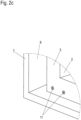
- the arrangement of the opening device 10 and the door hinge 9 in the upper area of the refrigerator 1 is shown in the detail enlargements in FIGS figures 2a and 2b shown again in more detail.
- the door hinge 9 used is, for example, a so-called seven-bar hinge, which has seven different points of articulation. Such joints have established themselves as a standard in refrigeration devices, since they can be used to achieve a suitably guided opening movement of the door arrangement.
- a space of a certain width, depth and height extends in the horizontal direction along the front face 3, the height extends in the vertical direction along the face 3 and the depth extends in a direction perpendicular to the face 3 of the insulating body 2.
- the depth is specified as standard for the door hinges 9 that are usually used and is approximately 42 mm.
- the depth indicates the distance between the front surface 3 of the insulating body 2 and the surface of the body door 8 facing the insulating body 2 .
- the door hinge 9 bears against the two surfaces mentioned, the front end face 3 or the inner surface of the carcass door 8 with contact surfaces and is fastened to these elements with fastening means, usually screws.
- the position of the fasteners is also specified as standard.
- the insulating body 2 of the cooling device 1 are prefabricated fastening devices, eg screw-in options arranged so that the door hinge 9 can be screwed onto the end face 3 in the corner area.
- the fastening devices can be provided, for example, by inserted or pressed-in threaded bushes.
- the refrigeration device 1 allows, as is usual with refrigeration devices, a left-hand or right-hand door stop.
- the fastening devices mentioned for the door hinge(s) 9 are provided not only on the right-hand side of the insulating body 2, but in mirror image on the left-hand side.
- the door hinges 9 can thus also be screwed onto the left side of the refrigerator in the upper left or lower left corner without any other structural changes. If the door hinges 9 are not symmetrical, they are swapped over crosswise when the door hinges change, i.e. the upper right door hinge 9 is inserted at the bottom left and the lower right door hinge 9 at the top left.
- the installation space that would be available for the upper one of the door hinges 9 when the door was hinged on the left is occupied by the opening device 10 .
- the opening device 10 is advantageously not only positioned in this installation space, but also uses the prepared fastening devices for the door hinge 9. With a door hinged on the left, the door hinge 9 would use these fastening devices on the left side, whereas the opening device 10, in the illustrated state, is from the top Door hinge 9 used mounting options in the upper right corner of the insulator 9 would use.
- an opening device 10 can be arranged not only in the upper but also in the lower area of the cooling device 1 or both in the upper and in the lower area.
- the opening device 10 could therefore also use the fastening devices for the lower of the two door hinges 9 on the side on which the door hinge is not installed.
- the fasteners mentioned in the lower left corner of the refrigerator 1 are in the Figures 1a and 1b shown.
- the Figure 2c shows the lower left corner area of the cooling device 1 in an enlarged detail.
- the fastening devices are in this case threaded inserts 11 in the end face 3 of the insulating body 2, into which a fastening screw is screwed in this illustration in order to cover the threaded inserts 11 when they are not in use.
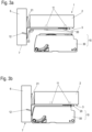
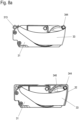
- FIG. 3a and 3b a first exemplary embodiment of an opening device 10 is shown, which is arranged in an upper or lower corner area of an insulating body 2 of a cooling device 1, which is otherwise not shown in any more detail here.
- the figures show a plan view of the corner area mentioned, whereby part of the insulating body 2 can be seen as well as a side wall of the furniture body 6.
- the opening device 10 is constructed in two parts with a mounting base 20 and a functional unit 30 that can be removed from the mounting base 20 .
- the mounting base 20 is first attached to the refrigerator 1 and the furniture body 6 in the corner area mentioned.
- screws 12 are screwed into the threaded inserts 11 of the cooling device 1 .
- the threaded inserts 11 are the fastening points for the door hinges already provided in the insulating body 2 of the cooling device 1, which are unused on the side opposite the inserted door hinges 9 and are available.
- the mounting base 20 is designed in the form of an L-shaped angle, which bears against the insulating body 2 with a longer leg. A shorter leg of the mounting base 20 is supported on the furniture body 6 . Provision can also be made for a fastening hole 23 to be provided in the mounting base 20 here, through which a self-tapping screw 12 can be screwed into the furniture body 6 .
- contacts 22 are arranged on the mounting base 20 and are connected to a connection cable 21 of the opening device 10 .
- the contacts 20 are arranged in a connector which is positioned in a corner area of the angled mounting base 20 .
- a gap remains between the insulating body 2 of the cooling device 1 and the side wall of the furniture body 6, through which the connecting cable 21 can be routed in order to connect it to a mains supply in the rear area of the cooling device 1 (not visible here), if necessary via a intermediate power supply.
- the connecting cable 21 can also include signal lines in order to connect the opening device to a sensor arrangement.
- An example of a sensor arrangement via which a manually initiated opening of the door arrangement of the Cooling device 1 is detected in order to trigger the function of the opening device 10 is in figure 9 shown.
- the functional unit 30 is attached to the screwed-on mounting base 20 .
- This attachment is advantageously carried out using a tool-free (locking) mechanism.
- By placing the functional unit 30 is over in the Figures 3a and 3b Not visible mating contacts of the functional unit 30 an electrical connection with the contacts 22 and thus the connection cable 21 made.
- the functional unit 30 can be easily replaced without the wiring of the connecting cable 21 having to be detached or reconnected, or without the connecting cable 21 having to be rerouted.
- the functional unit 30 can be replaced, for example, for repair, service and/or cleaning purposes. The replacement can be performed by the user or an unskilled service technician.
- FIG 4 shows in an isometric view the mounting base 20 of the embodiment of FIG Figures 3a and 3b more detailed.
- the mounting base 20 itself is constructed in two parts, with a soft intermediate layer 25 being provided, onto which an upper part of the mounting base 20 is placed.
- the upper part can be made of a hard plastic and the intermediate layer 25 can be made of a soft plastic, rubber or an elastomer, for example.
- a high stability of the mounting base 20 is achieved and at the same time good sound decoupling and/or sound absorption is achieved, so that vibrations generated by the opening device 10 are not transmitted to the cooling device 1 or the furniture body 6 as structure-borne noise.
- the mounting base 20 has mounting bores 23 which can be embodied as oblong holes in order to be able to move the mounting base 20 on the insulating body 2 and thus to be able to compensate for different gap dimensions between the cooling device 1 and the furniture body 6 .
- Another way of compensating for different gap dimensions is by inserting spacer plates.
- Fastening means 24 are also arranged on the mounting base 20 and serve to fasten the functional unit 30 to the mounting unit 20 . This can be latching elements and/or guides, possibly with undercuts.
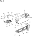
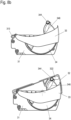
- figure 5 shows in its right part the opening device 10 with a separate mounting base 20 and functional unit 30 again in an isometric representation.
- the functional unit 30 is shown from a different perspective in the left-hand part of the figure.
- FIG. 5 That related to figure 4 already mentioned fastening the functional unit 30 on the mounting base 20 is in the figure 5 shown in more detail.
- Latching elements and guide webs with undercut areas are provided as fastening means 24 on the mounting base 20 in order to be able to slide the functional unit 30 onto the mounting base.
- the functional unit 30 has fastening means 312 that interact with these.
- the movement sequence provided for fastening is represented by two movement arrows 13,14.
- the functional unit 30 is first placed on the mounting base 20 and then pushed parallel to the longer leg of the mounting base 20 in the direction of the shorter leg, as indicated by the movement arrow 14 .
- Sections of the functional unit 30 engage behind corresponding sections of the guide webs of the mounting base 20 and at the same time mating contacts 311 of the functional unit 30 make contact with the contacts 22 of the mounting base 20.
- the functional unit 30 latches with its fastening means 312 the locking means of the mounting base 20, whereby the functional unit 30 is fixed in the pushed-on position. Additional fixing elements such as screws or a cotter pin can be provided.
- the figure 5 also shows details of the structure of the functional unit 30.
- This has a base body 31, the underside of which is pushed onto the mounting base 20 and on which the counter-contacts 311 mentioned are also arranged.
- the functional unit 30 also has an ejector element 32, which pivots open when the opening device 10 is functioning in order to open the door arrangement (cf. insulating door 4 and carcass door 8 in FIGS Figures 1a and 1b ) of the cooling device 1 to push open.
- the ejector element 32 is hood-shaped and slipped over the base body 31 . It is provided with a pivot bearing hole 321 with which it is mounted on the base body 31 .
- a guide curve 322 is formed on the ejection element 32, whose function in connection with the figures 7 and 8a-c will be explained in more detail.
- a further pivot bearing bore 323 is formed on the ejection element 32, the function of which is also explained below.
- a soft component can be arranged along the edge with which the ejector element 32 bears against the door arrangement, in particular it can be injection-molded on or molded on in a co-extrusion process.
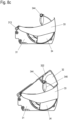
- FIG 6 shows another embodiment of an opening device 10, which differs from the previously shown embodiment by the way the functional unit 30 is attached to the mounting base 20.
- the other function of the opening device 10 reference is made to the following statements on the first exemplary embodiment.
- the functional unit 30 is fastened to the mounting base 20 not by placing it on and moving it, but rather by hooking it in and pivoting it in. Hooking is symbolized by a movement arrow 15 and pivoting in by a movement arrow 16 .
- the functional unit 30 in this example has a rearwardly protruding projection as the fastening means 312 and the mounting base 20 has a receptacle as the fastening means 24 into which the projection is inserted. After insertion, the functional unit 30 is pivoted at the opposite end of the projection onto the mounting base 20 and locked there with locking means in the figure 6 are not visible.
- the contacts 22 and the counter-contacts 311 are also arranged differently and in particular have a different plug-in direction than in the first exemplary embodiment, which is adapted to pivoting in according to the movement arrow 16 .
- figure 7 12 shows the structure of the opening device 10 of the first embodiment in more detail.
- the Indian figure 7 visible internal structure of the functional unit 30 and the functionality achieved with it are analogous to the second exemplary embodiment according to FIG figure 6 implemented.
- the figure 7 shows the opening device 10 in the form of an isometric exploded drawing.
- the base body 31 of the functional unit 30 is inserted into the mounting base 20 .
- the ejection element 32 is in the form of a hood placed on the base body 31, bearing pins 313 being formed on the base body 31, which engage in the corresponding pivot bearing bore 321 of the ejector element 32 on both sides, so that the latter is pivotably attached to the base body 31.
- a semi-circular pivoting element 34 is rotatably mounted on the base body 31 on the side of the base body 31 opposite the bearing journal 313 .
- the pivoting element 34 is composed of two circular segments 341a, 341b, which are each placed on the base body 31 from one side, with a rotary axis 342 being rotatably mounted in a bearing bore 314.
- the assembled circle segments 341a, b are connected to each other in the axis of rotation 342 and in a connecting axis 343 arranged eccentrically to this.
- the connecting axis 343 protrudes outwards beyond the outer surfaces of the circular segments 341a, b, with rotatably mounted rollers 344 being placed on the connecting axes 343 in the protruding area. These rollers 344 engage in the previously mentioned guide curves 322 of the ejection element 32 . When the pivoting element 34 pivots, the rollers 344 move along the guide curve 322 and pivot the ejection element 32 out. This will be detailed in connection with the Figures 8a-8c described.
- a motor 315 is arranged in the base body 31, which acts on two drive gears 316 via a gear (not visible here), which in turn interact with a gear segment 345 of each circle segment 341a, b.
- the gear can be a worm gear, for example.
- the motor 315 can preferably be mounted elastically in order to ensure a drive that is as silent and vibration-free as possible.
- a weight can be attached to the motor 315 as a mass oscillator in order to further reduce vibration amplitudes.
- the gear segment 345 represents a section of an internal gear (also called a ring gear).
- an internal gear also called a ring gear.
- apron 33 arranged between the base body 31 and the ejection element, which can be pivoted with bearing pins 331 in the ejection element 32 is mounted in pivot bearing bores 323 .
- the pivot bearing 323 is adjacent to the pivot bearing 321 with which the ejection element 32 is mounted on the base body 31 .
- the apron 33 has the function of anti-pinch protection, as also in connection with those described below Figures 8a-8c is explained.
- the functional unit 30 is shown in three different functional positions, specifically in Figure 8a in a retracted position, in Figure 8b in a partially extended position and in Figure 8c a fully extended position of the ejection element 32.
- the figures each show the functional unit 30 in the upper part of the figure without the ejection element 32 in a side view and in the lower part of the figure with the ejection element 32 in a sectional view.
- the section is shown in a plane perpendicular to the pivot axis of the ejection element 32 just between the ejection element 32 and the skirt 33, so that the base body 31 and the skirt 33 in a side view and only the ejection element 32 is visible in section.
- the extension of the ejection element 32 is based on a rotation of the pivoting element 34, the rotational movement of which is converted into a pivoting movement of the ejection element 32 via the rollers 344.
- the guide curve 322 enables a larger pivoting angle of the ejection element 32 than would result solely from the rotary movement of the pivoting element 34 .
- the shape of the guide curve 322 also influences the angular dependency of the movement of the ejection element 32 as a function of the angle of rotation of the pivoting element 34. In this way, the most effective ejection movement can be achieved, which has a large ejection force at the beginning of the movement sequence, which is advantageous for avoiding magnetic locking forces of the door arrangement of the To overcome cooling device 1. This is followed by a higher speed burst to allow the door assembly to be burst open far enough. A progressive movement kinematics is generated in this way.
- the skirt 33 also performs a pivoting movement, but by a smaller deflection angle in such a way that a gap between the base body 31 and the ejection element 32 is closed at all times to prevent a finger, for example, being trapped when the ejection element 32 retracts again impede.
- a cam-like projection on the outside of the pivoting element 34 on the circular segments 341a, b 346 is formed, which presses on an upper or lower edge of the apron 33 and moves it accordingly.
- the shape of the projection 346 in conjunction with the shape of the edges of the skirt 33 determines the path of motion that the skirt 33 undergoes during movement of the pivot member 34 .
- a cam-like projection can also be formed on the ejection element 32 (pointing inwards in this case), which moves the apron 33 with it.
- a projection 346 can be provided for each direction of movement, so that the apron 33 is positively guided in both directions.
- the skirt 33 may have an inwardly pointing pin which moves along a guide groove machined into the outer surface of the respective circle segment 341a,b.
- the ejection element 32 can be extended or retracted by energizing the motor 315 with the appropriate polarity.
- At least one end stop switch can be provided, which is arranged inside the base body 31 and is actuated, for example, by an inwardly pointing cam on one of the circle segments 341a, b and stops the motor 315 in an end position. In principle, both end positions can be determined using switches.
- a circuit driving the motor 315 monitors the power consumption of the motor 315 and detects a mechanical end stop due to the increased power consumption and then stops the motor 315 .
- An electronic circuit for controlling the motor 315 and/or evaluating limit switches is preferably arranged in the functional unit 30, e.g. in the base body 31.
- a sensor can be arranged on the cooling device 1 or on the furniture body 6, which sensor detects a manually initiated opening process of the door arrangement, whereupon the ejection process of the opening device 10 is started.
- figure 9 shows an example of a sensor arrangement 40 suitable for this purpose, which is positioned on the furniture carcass 6 on the side of the door that is not hinged.
- the sensor arrangement 40 includes a pressure-dependent resistor 42 which is embedded in an elastic casing 41 .
- An adhesive film is preferably provided on the back of the casing, which allows for easy assembly. Alternatively or additionally, a screw fastening can take place.
- the shroud 41 has an actuator 43 at the appropriate location which protrudes slightly.
- a fixed housing can also be provided, in which the pressure-dependent resistor 42 is arranged and from which a movable actuator 43 protrudes.
- the pressure-dependent resistor 42 (FSR-force sensitive resistor) changes its resistance value when force is applied.
- the sensor arrangement 40 is positioned in such a way that the closed carcass door 8 presses on the pressure-dependent resistor 42 via the actuator 43 . If this pressure is absent when the carcass door 8 is moved, the resistance value of the pressure-dependent resistor 42 changes, which is detected by a corresponding monitoring circuit.
- the movement of the carcass door 8 can also be detected via a mechanical button, a reflected light barrier, a strain gauge, a piezoelectric element or a magnetic sensor in conjunction with a permanent magnet arranged in the carcass door 8 .
- a control device of the cooling device 1 for example a touch screen or via a network-enabled or SmartHome-enabled device, for example a smartphone or a voice input device.
Description
Die Erfindung betrifft eine Öffnungsvorrichtung für ein Kühlgerät mit einer Türanordnung, wobei die Öffnungsvorrichtung eine Montagebasis aufweist, die an vorgesehenen Befestigungseinrichtungen für einen Türscharnier des Kühlgeräts montierbar ist, und eine Funktionseinheit mit einem Ausstoßelement aufweist, das elektrisch angesteuert ausfahrbar ist.The invention relates to an opening device for a refrigeration appliance with a door arrangement, the opening device having a mounting base which can be mounted on fastening devices provided for a door hinge of the refrigeration appliance, and having a functional unit with an ejection element which can be extended in an electrically controlled manner.
Im Haushalt übliche Kühlgeräte wie beispielsweise Kühlschränke oder Gefrierschränke weisen in der Regel eine schwenkbare Tür auf, die mit einer umlaufenden Dichtung gegenüber dem Korpus des Kühlgeräts abgedichtet ist. Um eine ausreichende Wärmeisolierung ohne Leckagen zwischen dem Isolierkorpus und der Isoliertür zu erzielen, ist die umlaufende Dichtung typischerweise als eine Magnetdichtung ausgebildet, die Zuhaltekräfte zwischen der Tür und dem Korpus aufbringt. Zudem können die Türscharniere mit einer Selbsteinzugsfunktion ausgestattet sein, die zusätzliche Zuhaltekräfte erbringt. Schließlich bildet sich nach dem Schließen einer Kühlschrank- oder Gefrierschranktür aufgrund der eingetretenen wärmeren Luft, die dann im Inneren abkühlt ein Unterdruck in dem hermetisch abgedichteten Innenraum, der der Zuhaltekraft eine weitere Komponente beisteuert.Common household refrigerators, such as refrigerators or freezers, generally have a pivoting door that is sealed off from the body of the refrigerator with a peripheral seal. In order to achieve sufficient thermal insulation without leakage between the insulating body and the insulating door, the circumferential seal is typically designed as a magnetic seal that applies locking forces between the door and the body. In addition, the door hinges can be equipped with a self-closing function that provides additional locking forces. Finally, after the closing of a refrigerator or freezer door, due to the warmer air that has entered, which then cools down inside, a negative pressure forms in the hermetically sealed interior, which contributes another component to the locking force.
Zur bequemeren Handhabung eines derartigen Kühlgeräts sind die eingangs genannten Öffnungsvorrichtungen bekannt, bei denen aus einem Gehäuse ein Ausstoßelement elektrisch angetrieben ausfahrbar ist, mit dem die Tür des Kühlgeräts zumindest soweit aufgeschoben wird, dass die Tür bequem hintergriffen werden kann und dann manuell vollständig geöffnet werden kann.For more convenient handling of such a cooling device, the opening devices mentioned at the outset are known, in which an ejection element can be extended from a housing in an electrically driven manner, with which the door of the cooling device is pushed open at least far enough that the door can be easily reached from behind and then opened completely manually .
Eine derartige Öffnungsvorrichtung ist beispielsweise aus der Druckschrift
Die Druckschrift
Es ist eine Aufgabe der vorliegenden Erfindung, eine Öffnungsvorrichtung für ein Kühlgerät zu schaffen, die in dem vorgesehenen Bauraum für die Türscharniere eingesetzt werden kann und die zu Service- oder Reparaturzwecken einfach ausgetauscht werden kann.It is an object of the present invention to create an opening device for a refrigerator that can be used in the installation space provided for the door hinges and that can be easily replaced for service or repair purposes.
Diese Aufgabe wird durch eine Öffnungsvorrichtung für ein Kühlgerät mit den jeweiligen Merkmalen des Anspruchs 1 gelöst. Vorteilhafte Ausgestaltungen und Weiterbildungen sind Gegenstand der abhängigen Ansprüche.This object is achieved by an opening device for a refrigerator with the respective features of
Eine erfindungsgemäße Öffnungsvorrichtung der eingangs genannten Art zeichnet sich dadurch aus, dass die Montagebasis Kontakte und die Funktionseinheit Gegenkontakte aufweist, wobei die Kontakte und die Gegenkontakte bei einem Befestigen der Funktionseinheit an der Montagebasis zur Stromversorgung der Funktionseinheit miteinander kontaktieren.An opening device according to the invention of the type mentioned above is characterized in that the mounting base has contacts and the functional unit has counter-contacts, the contacts and the counter-contacts contacting one another when the functional unit is fastened to the mounting base to supply power to the functional unit.
Aufgrund der zweiteiligen Ausführung der Öffnungsvorrichtung mit Montagebasis und Funktionseinheit, deren Kontakte/Gegenkontakte beim Aufmontieren der Funktionseinheit miteinander kontaktieren, kann die Funktionseinheit leicht ausgetauscht werden, ohne dass die Verkabelung eines Anschlusskabels zu lösen oder neu zu verbinden wäre oder dass ein Anschlusskabel neu zu verlegen wäre. Ein Austausch der Funktionseinheit kann beispielsweise zu Reparatur-, Service- und/oder Reinigungszwecken erfolgen. Der Austausch kann durch den Benutzer oder einen ungelernten Servicetechniker vorgenommen werden.Due to the two-part design of the opening device with mounting base and functional unit, whose contacts/counter-contacts make contact with one another when the functional unit is mounted, the functional unit can be easily replaced without the wiring of a connecting cable having to be disconnected or reconnected, or without a connecting cable having to be rerouted . The functional unit can be replaced, for example, for repair, service and/or cleaning purposes. The replacement can be performed by the user or an unskilled service technician.
Die Kontakte der Montagebasis sind dabei mit einem Anschlusskabel verbunden, das Stromversorgungsleitungen und ggf. Signalleitungen aufweist.The contacts of the mounting base are connected to a connection cable that has power supply lines and, if necessary, signal lines.
Zur mechanischen Befestigung der Funktionseinheit an der Montagebasis weisen die Montagebasis und die Funktionseinheit in einer vorteilhaften Ausgestaltung ineinander eingreifende Befestigungsmittel auf. Bevorzugt sind die Befestigungsmittel so ausgebildet, dass die Funktionseinheit werkzeuglos an der Montagebasis befestigt werden kann. Die Befestigungsmittel umfassen z.B. Rastmittel, Führungsstege, Haken, Ösen und/oder Hinterschnitte.In order to mechanically fasten the functional unit to the mounting base, in an advantageous embodiment the mounting base and the functional unit have fastening means which engage in one another. The fastening means are preferably designed in such a way that the functional unit can be fastened to the mounting base without the use of tools. The fastening means include, for example, locking means, guide webs, hooks, eyes and/or undercuts.
Zur Befestigung der Montagebasis weist diese Montagebohrungen zur Verbindung mit dem Kühlgerät auf und bevorzugt ebenfalls zur Verbindung mit einem Möbelkorpus, in den das Kühlgerät aufgenommen (eingeschoben) ist. Die Montagebasis kann dazu beispielsweise L-förmig ausgebildet sein. Bevorzugter Einbauort der Öffnungsvorrichtung ist der standardmäßig bei dem Kühlgerät vorgesehene Bauraum für die Türscharniere. Es ist dann besonders vorteilhaft, auch von den in diesem Zusammenhang bereits vorbereiteten Befestigungseinrichtungen der Türscharniere zur Befestigung der Montagebasis Gebrauch zu machen. Daraus ergibt sich eine einfache Nachrüstbarkeit einer erfindungsgemäßen Öffnungsvorrichtung für eine Vielzahl von Kühlgeräten, die bereits auf dem Markt erhältlich sind. Zudem wird kein anderweitig nutzbarer Bauraum, beispielsweise an einer Oberseite des Kühlgeräts belegt. Schließlich ist ein Eingriff in den Isolierkorpus, der über die sowieso vorhandenen Befestigungseinrichtungen der Türscharniere hinausgeht, nicht erforderlich.In order to fasten the mounting base, it has mounting bores for connection to the cooling device and preferably also for connection to a furniture body into which the cooling device is accommodated (slide in). For this purpose, the mounting base can be L-shaped, for example. The preferred installation location for the opening device is the standard installation space provided for the door hinges in the refrigerator. It is then particularly advantageous to also use the fastening devices for the door hinges, which have already been prepared in this connection, for fastening the mounting base. This means that an opening device according to the invention can be easily retrofitted for a large number of cooling devices that are already available on the market. In addition, no other space that can be used, for example on a top side of the cooling device, is occupied. Finally, an intervention in the insulating body, which goes beyond the fastening devices of the door hinges that are present anyway, is not necessary.
Über die Montagebasis ist erfindungsgemäß ein Mindestabstand zwischen dem Möbelkorpus und dem Kühlgerät zur Durchführung des Anschlusskabels definiert.According to the invention, a minimum distance between the furniture body and the cooling device for the passage of the connecting cable is defined via the mounting base.
Um in dem zur Verfügung stehenden Bauraum angeordnet werden zu können, weist das Gehäuse der Öffnungsvorrichtung vorteilhaft eine Tiefe von weniger als 60 Millimetern (mm), bevorzugt weniger als 47 mm oder bevorzugt zwischen 38 und 47 mm auf.In order to be able to be arranged in the available installation space, the housing of the opening device advantageously has a depth of less than 60 millimeters (mm), preferably less than 47 mm or preferably between 38 and 47 mm.
In einer bevorzugten Ausgestaltung der Öffnungsvorrichtung weist das Ausstoßelement einen maximalen Hub von 40 mm bis 80 mm auf. Mit einem derartigen Hub kann die Türanordnung so weit geöffnet werden, dass die Zuhaltekraft der (Magnet-) Dichtung und des Unterdrucks im Innenraum des Kühlgeräts überwunden werden. Die Türanordnung kann dann bequem hintergriffen werden, um sie vollständig zu öffnen. Gleichzeitig wird die Türanordnung bevorzugt nur so weit durch die Öffnungsvorrichtung geöffnet, dass sie sich noch im Selbsteinzugsbereich der Türscharniere befindet, wenn diese mit einem Selbsteinzug ausgestattet sind. Wird die Türanordnung nicht manuell geöffnet, schließt sie dann nach Wiedereinzug des Ausstoßelements selbstständig.In a preferred embodiment of the opening device, the ejection element has a maximum stroke of 40 mm to 80 mm. With such a lift, the door arrangement can be opened far enough for the locking force of the (magnetic) seal and the negative pressure in the interior of the refrigerator to be overcome. The door arrangement can then be easily reached from behind to open it fully. At the same time, the door arrangement is preferably only opened so far by the opening device that it is still in the self-closing area of the door hinges if they are equipped with a self-closing mechanism. If the door arrangement is not opened manually, it then closes automatically after the ejection element is retracted.
In einer weiteren vorteilhaften Ausgestaltung der Öffnungsvorrichtung ist das Ausstoßelement schwenkbar an einem Grundkörper gelagert und umgibt in einer nicht ausgeschwenkten Stellung den Grundkörper haubenförmig an zumindest vier Seiten. Bevorzugt weist die Öffnungsvorrichtung ein an dem Grundkörper schwenkbar gelagertes Schwenkelement mit mindestens einem innen liegendem Zahnradsegment auf, das über ein Antriebszahnrad mit einem elektrischen Motor gekoppelt ist und von dem Motor gegenüber dem Grundkörper verschwenkbar ist. Das Schwenkelement bewegt dabei das Ausstoßelement mit, bevorzugt über mindestens eine exzentrisch am Schwenkelement angeordnete Rolle, die sich entlang einer Führungskurve des im Ausstoßelements bewegt.In a further advantageous embodiment of the opening device, the ejection element is pivotably mounted on a base body and, in a non-pivoted position, surrounds the base body in the form of a hood on at least four sides. The opening device preferably has a pivoting element which is pivotably mounted on the base body and has at least one internal gear wheel segment which is coupled to an electric motor via a drive gear wheel and can be pivoted by the motor relative to the base body. The pivoting element moves the ejection element with it, preferably via at least one roller which is arranged eccentrically on the pivoting element and moves along a guide curve in the ejection element.
Die Führungskurve ermöglicht dabei einen größeren Schwenkwinkel des Ausstoßelements als sich alleine aufgrund der Drehbewegung des Schwenkelements ergeben würde. Über eine Formgebung der Führungskurve lässt sich zudem die Winkelabhängigkeit der Bewegung des Ausstoßelements abhängig vom Drehwinkel des Schwenkelements beeinflussen. So kann eine möglichst effektive Ausstoßbewegung erzielt werden, die zum Beginn des Bewegungsablaufes eine große Ausstoßkraft aufweist, die vorteilhaft ist, um magnetische Zuhaltekräfte der Türanordnung des Kühlgerätes zu überwinden. Danach erfolgt ein Aufstoßen mit größerer Geschwindigkeit, um die Türanordnung weit genug aufstoßen zu können.The guide curve enables a larger pivoting angle of the ejection element than would result solely from the rotary movement of the pivoting element. The angle dependency of the movement of the ejection element can also be influenced as a function of the angle of rotation of the pivoting element by shaping the guide curve. In this way, an ejection movement that is as effective as possible can be achieved, which at the beginning of the movement sequence has a large ejection force, which is advantageous in order to overcome magnetic locking forces of the door arrangement of the refrigerator. This is followed by a higher speed burst to allow the door assembly to be burst open far enough.
In einer weiteren vorteilhaften Ausgestaltung weist die Öffnungsvorrichtung eine an dem Grundkörper oder dem Ausstoßelement schwenkbar gelagerte Schürze auf, die sich als Einklemmschutz zwischen dem Grundkörper und dem Ausstoßelement erstreckt. Bevorzugt wird die Schürze durch das Schwenkelement und/oder das Ausstoßelement in zumindest eine Bewegungsrichtung zwangsgeführt mitbewegt. Durch eine zwangsgeführte Mitbewegung der Schürze wird sichergestellt, dass sich diese jederzeit in einer geeigneten Position befindet, in der sie ein Einklemmen beispielsweise eines Fingers beim Wiedereinfahren des Ausstoßelements verhindert.In a further advantageous embodiment, the opening device has an apron which is pivotably mounted on the base body or the ejection element and which extends between the base body and the ejection element as protection against pinching. The apron is preferably also moved in a forcibly guided manner in at least one movement direction by the pivoting element and/or the ejection element. A forced movement of the apron ensures that it is always in a suitable position in which it prevents a finger, for example, from getting caught when the ejection element is retracted again.
In einer weiteren vorteilhaften Ausgestaltung der Öffnungsvorrichtung ist der elektrische Motor über ein Schneckengetriebe mit dem Antriebszahnrad gekoppelt. So kann mit nur einer Getriebestufe platzsparend ein geeignetes Übersetzungsverhältnis erzielt werden. Bevorzugt ist der elektrische Motor vibrationsdämpfend in oder an dem Grundkörper befestigt. Es wird so ein möglichst lautloser Betrieb der Öffnungsvorrichtung erzielt.In a further advantageous embodiment of the opening device, the electric motor is coupled to the drive gear wheel via a worm gear. In this way, a suitable transmission ratio can be achieved in a space-saving manner with just one gear stage. The electric motor is preferably fastened in or on the base body in a vibration-damping manner. In this way, operation of the opening device is as silent as possible.
Die Erfindung wird nachfolgend anhand von Figuren näher erläutert. Die Figuren zeigen:
- Figuren 1a, 1b
- jeweils eine isometrische Ansicht eines Kühlgeräts mit geöffneter Tür aus verschiedenen Blickrichtungen;
- Figuren 2a, 2b
- Detaildarstellungen aus den
Figuren 1a ,1b , die die Anordnung einer Öffnungsvorrichtung bzw. eines Türscharniers im Kühlgerät derFiguren 1a ,1b detaillierter zeigen; - Figur 2c
- eine Detaildarstellung aus den
Figuren 1a ,1b , die einen Bauraum für einen Türscharnier oder eine Öffnungsvorrichtung detaillierter zeigt; - Figuren 3a, 3b
- jeweils eine Seitenansicht eines ersten Ausführungsbeispiels einer Öffnungsvorrichtung in verschiedenen Montagezuständen;
Figur 4- eine isometrische Darstellung einer Montagebasis der Öffnungsvorrichtung des ersten Ausführungsbeispiels;
Figur 5- verschiedene isometrische Darstellung der Montageplatte und eines Funktionselements der Öffnungsvorrichtung des ersten Ausführungsbeispiels;
Figur 6- eine Seitenansicht eines zweiten Ausführungsbeispiels einer Öffnungsvorrichtung während einer Montage;
Figur 7- eine isometrische Explosionsdarstellung der Öffnungsvorrichtung des ersten Ausführungsbeispiels;
- Figuren 8a-8c
- jeweils eine Seite und ein Schnittdarstellung der Öffnungsvorrichtung des ersten Ausführungsbeispiels in verschiedenen Betriebsstellungen; und
Figur 9- eine schematische Darstellung einer Sensoranordnung zum Auslösen einer Öffnungsvorrichtung.
- Figures 1a, 1b
- each an isometric view of a refrigerator with the door open from different perspectives;
- Figures 2a, 2b
- Details from the
Figures 1a ,1b , Which the arrangement of an opening device or a door hinge in the refrigeratorFigures 1a ,1b show in more detail; - Figure 2c
- a detail from the
Figures 1a ,1b - Figures 3a, 3b
- each a side view of a first embodiment of an opening device in different states of assembly;
- figure 4
- an isometric view of a mounting base of the opening device of the first embodiment;
- figure 5
- different isometric representation of the mounting plate and a functional element of the opening device of the first embodiment;
- figure 6
- a side view of a second embodiment of an opening device during assembly;
- figure 7
- an isometric exploded view of the opening device of the first embodiment;
- Figures 8a-8c
- one side and one sectional view of the opening device of the first exemplary embodiment in different operating positions; and
- figure 9
- a schematic representation of a sensor arrangement for triggering an opening device.
In den
Das Kühlgerät 1 weist einen wärmeisolierten Korpus, nachfolgend Isolierkorpus 2 genannt, auf, dessen Innenraum sowie dessen vordere Stirnfläche 3 in den dargestellten Figuren sichtbar ist. Dem Isolierkorpus 2 ist eine wärmeisolierte Tür, nachfolgend Isoliertür 4 genannt, zugeordnet, die eine umlaufende Dichtung 5, in der Regel eine Magnetdichtung, aufweist. Bei geschlossener Isoliertür 4 liegt die Dichtung 5 umlaufend auf der vorderen Stirnfläche 3 des Isolierkorpus 2 auf und verschließt somit den Innenraum des Isolierkorpus 2 hermetisch.The
Bei dem dargestellten Kühlgerät 1 ist der Isolierkorpus 2 in einen Möbelkorpus 6 eingebaut, dem eine Korpustür 8 zugeordnet ist, die im geschlossenen Zustand an einer vorderen Stirnfläche 7 des Möbelkorpus 6 anliegt.In the
In dem dargestellten Ausführungsbeispiel bilden die Korpustür 8 und die Isoliertür 4 eine fest miteinander verbundene Einheit. Alternativ kann die Korpustür 8 auch als sogenannte Schlepptür mit der Isoliertür verbunden sein. Die Korpustür 8 ragt zu allen Seiten nach außen über die Isoliertür 4 hervor. Die Isoliertür 4 ist über Türscharniere 9 mit dem Isolierkorpus 2 des Kühlgeräts 1 schwenkbar verbunden. Die eigentliche Gelenkmechanik des jeweiligen Türscharniers 9 ist dabei oberhalb bzw. unterhalb der Isoliertür 4 angeordnet, sodass sie bei geschlossenem Kühlgerät 1 außerhalb des isolierten Innenraums des Isolierkorpus 2 liegt. Die Korpustür 8 wird über eine in den
Im oberen linken Eckbereich des Isolierkorpus 2 ist eine Öffnungsvorrichtung 10 angeordnet, die dem elektrisch angetriebenen Aufstoßen der Türanordnung, d.h. der Einheit aus Korpustür 8 und Isoliertür 4, dient.An
Die Anordnung der Öffnungsvorrichtung 10 bzw. des Türscharniers 9 im oberen Bereich des Kühlgeräts 1 ist in den Ausschnittvergrößerungen in den
Für das Türscharnier 9 steht im Eckbereich des Isolierkorpus 2 ein Bauraum einer bestimmten Breite, Tiefe und Höhe zur Verfügung. Die Breite erstreckt sich dabei in horizontaler Richtung entlang der vorderen Stirnfläche 3, die Höhe erstreckt sich in vertikaler Richtung entlang der Stirnfläche 3 und die Tiefe erstreckt sich in einer Richtung senkrecht zur Stirnfläche 3 des Isolierkorpus 2.For the
Insbesondere die Tiefe ist bei den üblicherweise eingesetzten Türscharnieren 9 standardmäßig festgelegt und beträgt etwa 42 mm. Die Tiefe gibt den Abstand zwischen der Stirnfläche 3 des Isolierkorpus 2 und der dem Isolierkorpus 2 zugewandten Fläche der Korpustür 8 an. An den beiden genannten Flächen, der vorderen Stirnfläche 3 bzw. der Innenfläche der Korpustür 8 liegt das Türscharnier 9 mit Anlageflächen an und ist mit Befestigungsmitteln, üblicherweise Schrauben, an diesen Elementen befestigt. In der Regel ist auch die Position der Befestigungsmittel standardmäßig festgelegt. Insbesondere im Isolierkorpus 2 des Kühlgeräts 1 sind vorgefertigte Befestigungseinrichtungen, z.B. Einschraubmöglichkeiten so angeordnet, dass das Türscharnier 9 auf der Stirnfläche 3 im Eckbereich angeschraubt werden kann. Die Befestigungseinrichtungen können beispielsweise durch eingesetzte oder eingepresste Gewindebuchsen gegeben sein.In particular, the depth is specified as standard for the door hinges 9 that are usually used and is approximately 42 mm. The depth indicates the distance between the
Das Kühlgerät 1 ermöglicht, wie bei Kühlgeräten üblich, einen links- oder rechtsseitigen Türanschlag. Zu diesem Zweck sind die erwähnten Befestigungseinrichtungen für das bzw. die Türscharniere 9 nicht nur auf der rechten Seite des Isolierkorpus 2 vorgesehen, sondern spiegelbildlich auf der linken Seite. Die Türscharniere 9 können somit ohne bauliche sonstige Veränderungen auch auf der linken Seite des Kühlgeräts in der linken oberen bzw. linken unteren Ecke angeschraubt werden. Bei nicht symmetrisch aufgebauten Türscharnieren 9 werden diese beim Türanschlagwechsel über Kreuz getauscht, d.h. das rechte obere Türscharnier 9 wird links unten eingesetzt und das rechte untere Türscharnier 9 links oben.The
In der dargestellten Anordnung wird der Bauraum, der für das obere der Türscharniere 9 bei linksseitig angeschlagener Tür zur Verfügung stehen würde, von der Öffnungsvorrichtung 10 eingenommen. Vorteilhaft ist die Öffnungsvorrichtung 10 nicht nur in diesem Bauraum positioniert, sondern nutzt auch die vorbereiteten Befestigungseinrichtungen für das Türscharnier 9. Bei links angeschlagener Tür würde entsprechend das Türscharnier 9 diese Befestigungseinrichtungen auf der linken Seite nutzen, wogegen die Öffnungsvorrichtung 10 die im dargestellten Zustand vom oberen Türscharnier 9 verwendeten Befestigungsmöglichkeiten im rechten oberen Eckbereich des Isolierkörpers 9 verwenden würde.In the arrangement shown, the installation space that would be available for the upper one of the door hinges 9 when the door was hinged on the left is occupied by the
Es wird in diesem Zusammenhang angemerkt, dass eine Öffnungsvorrichtung 10 nicht nur im oberen, sondern auch im unteren Bereich des Kühlgeräts 1 oder sowohl im oberen als auch im unteren Bereich angeordnet sein kann. Die Öffnungsvorrichtung 10 könnte also auch die Befestigungseinrichtungen für das untere der beiden Türscharniere 9 auf entsprechend der Seite, auf der das Türscharnier nicht verbaut ist, nutzen. Die genannten Befestigungseinrichtungen im linken unteren Eckbereich des Kühlgeräts 1 sind in den
In den
Die Öffnungsvorrichtung 10 ist zweiteilig mit einer Montagebasis 20 und einer von der Montagebasis 20 abnehmbaren Funktionseinheit 30 aufgebaut.The
Zur Montage der Öffnungsvorrichtung 10 wird zunächst die Montagebasis 20 in dem genannten Eckbereich am Kühlgerät 1 sowie dem Möbelkorpus 6 befestigt. Dazu werden (Gewinde-)Schrauben 12 in die Gewindeeinsätze 11 des Kühlgeräts 1 eingeschraubt. Wie zuvor ausgeführt, sind die Gewindeeinsätze 11 die im Isolierkorpus 2 des Kühlgeräts 1 bereits vorgesehenen Befestigungsstellen für die Türscharniere, die auf der den eingesetzten Türscharnieren 9 gegenüberliegenden Seite ungenutzt sind und zur Verfügung stehen.To assemble the
Die Montagebasis 20 ist im vorliegenden Beispiel in Form eines L-förmigen Winkels ausgebildet, der mit einem längeren Schenkel am Isolierkorpus 2 anliegt. Ein kürzerer Schenkel der Montagebasis 20 stützt sich am Möbelkorpus 6 ab. Es kann vorgesehen sein, auch hier ein Befestigungsloch 23 in der Montagebasis 20 anzubringen, durch das eine selbstschneidende Schraube 12 in den Möbelkorpus 6 geschraubt werden kann.In the present example, the mounting
Erfindungsgemäß sind an der Montagebasis 20 Kontakte 22 angeordnet, die mit einem Anschlusskabel 21 der Öffnungsvorrichtung 10 verbunden ist. Die Kontakte 20 sind in dem dargestellten Ausführungsbeispiel in einem Steckverbinder angeordnet, der in einem Eckbereich der winkelförmig ausgebildeten Montagebasis 20 positioniert ist. In der Regel verbleibt zwischen dem Isolierkorpus 2 des Kühlgeräts 1 und der Seitenwand des Möbelkorpus 6 ein Spalt, durch den das Anschlusskabel 21 geführt werden kann, um es im hinteren, hier nicht sichtbaren Bereich des Kühlgeräts 1 an eine Netzversorgung anzuschließen, ggf. über ein zwischengeschaltetes Netzteil. Das Anschlusskabel 21 kann neben Stromversorgungsleitungen auch Signalleitungen umfassen, um die Öffnungsvorrichtung mit einer Sensoranordnung zu verbinden. Ein Beispiel einer Sensoranordnung, über die ein manuell initiiertes Öffnen der Türanordnung des Kühlgerätes 1 erfasst wird, um die Funktion der Öffnungsvorrichtung 10 auszulösen, ist in
An der angeschraubten Montagebasis 20 wird in einem nächsten Schritt die Funktionseinheit 30 befestigt. Diese Befestigung erfolgt vorteilhaft über einen werkzeuglosen (Rast-) Mechanismus. Durch das Aufsetzen der Funktionseinheit 30 wird über in den
Aufgrund der zweiteiligen Ausführung der Öffnungsvorrichtung 10 mit Montagebasis 20 und Funktionseinheit 30 kann die Funktionseinheit 30 so leicht ausgetauscht werden, ohne dass die Verkabelung des Anschlusskabels 21 zu lösen oder neu zu verbinden wäre oder dass Anschlusskabel 21 neu zu verlegen wäre. Ein Austausch der Funktionseinheit 30 kann beispielsweise zu Reparatur-, Service- und/oder Reinigungszwecken erfolgen. Der Austausch kann durch den Benutzer oder einen ungelernten Servicetechniker vorgenommen werden.Due to the two-part design of the
Die Montagebasis 20 weist neben den genannten Kontakten 22 Montagebohrungen 23 auf, die als Langlöcher ausgeführt sein können, um die Montagebasis 20 am Isolierkorpus 2 verschieben zu können und so unterschiedliche Spaltmaße zwischen dem Kühlgerät 1 und dem Möbelkorpus 6 ausgleichen zu können. Eine weitere Möglichkeit, um unterschiedliche Spaltmaße auszugleichen, ist durch zwischengelegte Distanzplättchen gegeben. Weiter sind an der Montagebasis 20 Befestigungsmittel 24 angeordnet, die einer Befestigung der Funktionseinheit 30 an der Montageeinheit 20 dienen. Dieses können Rastelemente und/oder Führungen, ggf. mit Hinterschnitten sein.In addition to the
Das im Zusammenhang mit
Die zum Befestigen vorgesehene Bewegungssequenz ist durch zwei Bewegungspfeile 13,14 dargestellt. Bei dem hier gezeigten Ausführungsbeispiel ist vorgesehen, die Funktionseinheit 30 zunächst auf die Montagebasis 20 aufzusetzen und dann parallel zu dem längeren Schenkel der Montagebasis 20 in Richtung des kürzeren Schenkels zu schieben, wie das der Bewegungspfeil 14 zeigt. Dabei hintergreifen Abschnitte der Funktionseinheit 30 entsprechende Abschnitte der Führungsstegen der Montagebasis 20 und gleichzeitig kontaktieren Gegenkontakte 311 der Funktionseinheit 30 die Kontakte 22 der Montagebasis 20. Am Ende der Schiebebewegung, die durch den Bewegungspfeil 14 symbolisiert wird, verrastet die Funktionseinheit 30 mit ihren Befestigungsmitteln 312 mit den Rastmitteln der Montagebasis 20, wodurch die Funktionseinheit 30 in der aufgeschobenen Position fixiert wird. Es können zusätzliche Fixierelemente wie Schrauben oder ein Splint vorgesehen sein.The movement sequence provided for fastening is represented by two
Die
Die Funktionseinheit 30 weist weiterhin ein Ausstoßelement 32 auf, das bei Funktion der Öffnungsvorrichtung 10 aufschwenkt, um die Türanordnung (vgl. Isoliertür 4 und Korpustür 8 in den
Anders als bei dem zuvor beschriebenen Ausführungsbeispiel erfolgt eine Befestigung der Funktionseinheit 30 auf der Montagebasis 20 nicht über ein Aufsetzen und Verschieben, sondern über ein Einhaken und Einschwenken. Das Einhaken ist durch einen Bewegungspfeil 15 und das Einschwenken durch einen Bewegungspfeil 16 symbolisiert. Zum Einhaken weist die Funktionseinheit 30 in diesem Beispiel als Befestigungsmittel 312 einen nach hinten hervorstehenden Vorsprung auf und die Montagebasis 20 als Befestigungsmittel 24 eine Aufnahme, in die der Vorsprung eingesetzt wird. Nach dem Einsetzen wird die Funktionseinheit 30 an deren dem Vorsprung gegenüber liegenden Ende auf die Montagebasis 20 eingeschwenkt und verrastet dort mit Rastmitteln, die in der
Entsprechend der geänderten Bewegungsabfolge sind auch die hier nicht sichtbaren Kontakte 22 und die Gegenkontakte 311 anders angeordnet und weisen insbesondere ein andere Steckrichtung als bei dem ersten Ausführungsbeispiel auf, die an das Einschwenken gemäß dem Bewegungspfeil 16 angepasst ist.According to the changed movement sequence, the
Die
An der den Lagerzapfen 313 gegenüberliegenden Seite des Grundkörpers 31 ist ein halbkreisförmiges Schwenkelement 34 drehbar am Grundkörper 31 gelagert. Das Schwenkelement 34 ist aus zwei Kreissegmenten 341a, 341b zusammengesetzt, die jeweils von einer Seite auf den Grundkörper 31 aufgesetzt sind, wobei eine Drehachse 342 in einer Lagerbohrung 314 drehbar gelagert ist. Die zusammengesetzten Kreissegmente 341a, b sind in der Drehachse 342 miteinander verbunden und in einer exzentrisch zu dieser angeordneten Verbindungsachse 343.A
Die Verbindungsachse 343 steht nach außen über Außenflächen der Kreissegmente 341a, b über, wobei in dem überstehenden Bereich drehbar gelagerte Rollen 344 auf die Verbindungsachsen 343 aufgesetzt sind. Diese Rollen 344 greifen in die bereits genannte Führungskurven 322 des Ausstoßelements 32 ein. Bei einem Verschwenken des Schwenkelements 34 bewegen sich die Rollen 344 entlang der Führungskurve 322 und schwenken das Ausstoßelement 32 aus. Dieses wird noch detailliert im Zusammenhang mit den
Zur Bewegung des Schwenkelements 34 und damit zur Bewegung des Ausstoßelements 32 ist im Grundkörper 31 ein Motor 315 angeordnet, der über ein hier nicht sichtbares Getriebe auf zwei Antriebszahnräder 316 wirkt, die wiederum mit einem Zahnradsegment 345 eines jeden Kreissegments 341a, b zusammenwirken. Das Getriebe kann z.B. ein Schneckengetriebe sein. Der Motor 315 kann bevorzugt elastisch gelagert sein, um einen möglichst lautlosen und vibrationsfreien Antrieb zu gewährleisten. Zusätzlich kann ein Gewichtsstück als Massenschwinger am Motor 315 angebracht werden, um Vibrationsamplituden weiter zu verringern.To move the pivoting
Das Zahnradsegment 345 stellt einen Abschnitt eines Innenzahnrads (auch Hohlzahnrad genannt) dar. Bei Drehung der Antriebszahnräder 316 schwenkt das Schwenkelement 34 um die Drehachse 342.The
Zudem ist noch eine zwischen dem Grundkörper 31 und dem Ausstoßelement angeordnete Schürze 33 vorhanden, die mit Lagerzapfen 331 schwenkbar in dem Ausstoßelement 32 in Schwenklagerbohrungen 323 gelagert ist. Das Schwenklager 323 ist benachbart zu dem Schwenklager 321, mit dem das Ausstoßelement 32 am Grundkörper 31 gelagert ist. Die Schürze 33 hat die Funktion eines Einklemmschutzes, wie ebenfalls in Zusammenhang mit den nachfolgend beschriebenen
In den
Das Ausfahren des Ausstoßelements 32 beruht auf einer Drehung des Schwenkelements 34, dessen Drehbewegung über die Rollen 344 in eine Schwenkbewegung des Ausstoßelements 32 umgesetzt wird. Die Führungskurve 322 ermöglicht dabei einen größeren Schwenkwinkel des Ausstoßelements 32 als sich alleine aufgrund der Drehbewegung des Schwenkelements 34 ergeben würde. Die Formgebung der Führungskurve 322 beeinflusst zudem die Winkelabhängigkeit der Bewegung des Ausstoßelements 32 abhängig vom Drehwinkel des Schwenkelements 34. So kann eine möglichst effektive Ausstoßbewegung erzielt werden, die zum Beginn des Bewegungsablaufes eine große Ausstoßkraft aufweist, die vorteilhaft ist, um magnetische Zuhaltekräfte der Türanordnung des Kühlgerätes 1 zu überwinden. Danach erfolgt ein Aufstoßen mit größerer Geschwindigkeit, um die Türanordnung weit genug aufstoßen zu können. Es wird so eine progressive Bewegungskinematik erzeugt.The extension of the
Bei der Schwenkbewegung des Ausstoßelements 32 vollführt auch die Schürze 33 eine Schwenkbewegung, allerdings jedoch um einen kleineren Auslenkwinkel gerade so, dass ein Spalt zwischen dem Grundkörper 31 und dem Ausstoßelement 32 jederzeit verschlossen ist, um ein Einklemmen beispielsweise eines Fingers beim Wiedereinfahren des Ausstoßelements 32 zu verhindern.During the pivoting movement of the
Um die Schürze 33 geeignet mitzubewegen, ist außen an dem Schwenkelement 34 an den Kreissegmenten 341a, b mindestens ein nockenartiger Vorsprung 346 ausgebildet, der auf eine obere bzw. untere Kante der Schürze 33 drückt und diese entsprechend mitbewegt. Die Formgebung des Vorsprungs 346 in Verbindung mit der Formgebung der Kanten der Schürze 33 bestimmt den Bewegungsablauf, den die Schürze 33 während der Bewegung des Schwenkelements 34 durchläuft. Alternativ oder zusätzlich kann auch an dem Ausstoßelement 32 ein nockenartiger Vorsprung ausgebildet sein (in dem Fall nach innen weisend), der die Schürze 33 mitbewegt.In order to move the
Es kann für jede Bewegungsrichtung ein Vorsprung 346 vorgesehen, so dass die Schürze 33 in beide Richtungen zwangsgeführt mitbewegt wird.A
Es ist auch denkbar, die Schürze 33 in einer Richtung durch eine Feder vorzuspannen und nur eine Bewegung entgegen der Federspannung durch einen Vorsprung 346 auf Seiten der oberen oder unteren Kante der Schürze 33 vorzunehmen. In dem Fall ist die Schürze 33 allerdings nicht in beide Richtungen zwangsgeführt.It is also conceivable to bias the
In einer alternativen Ausgestaltung kann auch eine andere Kopplung zwischen der Schürze 33 und dem Schwenkelement 34 vorgesehen sein. Beispielsweise kann die Schürze 33 einen nach innen weisenden Zapfen aufweisen, der sich entlang einer Führungsnut bewegt, die in die äußere Fläche des jeweiligen Kreissegments 341a, b eingebracht ist.In an alternative embodiment, a different coupling between the
Das Aus- bzw. Einfahren des Ausstoßelements 32 kann durch Bestromen des Motors 315 in entsprechender Polarität erfolgen. Es kann mindestens ein Endanschlagschalter vorgesehen sein, der innerhalb des Grundkörpers 31 angeordnet ist und z.B. von einem nach innen weisenden Nocken an einem der Kreissegmente 341a, b betätigt wird und den Motor 315 in einer Endposition stoppt. Es können so prinzipiell beide Endpositionen über Schalter ermittelt werden.The
Auch ist es denkbar, nur eine Endposition über einen derartigen Schalter zu bestimmen und über eine Erfasssung eines Drehwinkels des Motors 315 die Bewegung bis zur anderen Endposition zu kontrollieren. Zur Erfassung des Drehwinkels des Motors 315 kann dieser mit einem Drehgeber, z.B. einem Hallsensor ausgestattet sein. Alternativ kann auch eine elektronische Erfassung von Strompulsen erfolgen, die bei einem Kommutieren des Motors 315 entstehen. Aus den Strompulsen lässt sich die Motordrehung ableiten, falls der Motor 315 ein mechanisch kommutierter Motor ist. Bei Verwendung eines elektronisch kommutierten Motors als Motor 315 liegen die Informationen zum Kommutieren inhärent bei der Ansteuerung des Motors vor und können zur Drehwinkelbestimmung herangezogen werden.It is also conceivable to determine only one end position via such a switch and to control the movement up to the other end position by detecting an angle of rotation of the
Ebenfalls ist es möglich, dass eine den Motor 315 ansteuernde Schaltung die Stromaufnahme des Motors 315 überwacht und einen mechanischen Endanschlag aufgrund der erhöhten Stromaufnahme feststellt und dann den Motor 315 stoppt.It is also possible that a circuit driving the
Eine Elektronikschaltung zur Ansteuerung des Motors 315 und/oder Auswertung von Endschaltern ist bevorzugt in der Funktionseinheit 30, z.B. in dem Grundkörper 31 angeordnet.An electronic circuit for controlling the
Zum Auslösen der Öffnungsvorrichtung kann am Kühlgerät 1 bzw. am Möbelkorpus 6 ein Sensor angeordnet sein, der einen manuell initiierten Öffnungsvorgang der Türanordnung detektiert, woraufhin der Ausstoßvorgang der Öffnungsvorrichtung 10 gestartet wird.To trigger the opening device, a sensor can be arranged on the
Die Sensoranordnung 40 umfasst einen druckabhängigen Widerstand 42, der in eine elastische Ummantelung 41 eingebettet ist. Auf der Rückseite der Ummantelung ist bevorzugt eine Klebefolie vorhanden, die eine einfache Montage erlaubt. Alternativ oder zusätzlich kann eine Schraubbefestigung erfolgen. Die Ummantelung 41 weist an geeigneter Stelle einen Betätiger 43 auf, der leicht hervorsteht. Anstelle der elastischen Ummantelung 41 kann auch ein festes Gehäuse vorgesehen sein, in dem der druckabhängige Widerstand 42 angeordnet ist und aus dem ein beweglicher Betätiger 43 hervorsteht.The
Der druckabhängige Widerstand 42 (FSR-force sensitive resistor) ändert seinen Widerstandswert bei Kraftbeaufschlagung. Die Sensoranordnung 40 ist so positioniert, dass die geschlossene Korpustür 8 über den Betätiger 43 auf den druckabhängigen Widerstand 42 drückt. Entfällt dieser Druck, wenn die Korpustür 8 bewegt wird, ändert sich der Widerstandswert des druckabhängigen Widerstands 42, was durch eine entsprechende Überwachungsschaltung detektiert wird.The pressure-dependent resistor 42 (FSR-force sensitive resistor) changes its resistance value when force is applied. The
Anstelle des druckabhängigen Widerstands 42 kann eine Erkennung der Bewegung der Korpustür 8 auch über einen mechanischen Taster, eine Reflexlichtschranke, einen Dehnungsmessstreifen, ein Piezoelement oder einen Magnetsensor in Verbindung mit einem in der Korpustür 8 angeordneten Permanentmagneten erfolgen.Instead of the pressure-
Zum Auslösen der Öffnungsvorrichtung können auch weitere alternative im Stand bekannte Sensoren eingesetzt werden, die am Möbelkorpus 6 oder am Isolierkorpus oder an einem der Türen 4, 8 positioniert sind. Alternativ oder zusätzlich zu einem Sensor kann das Auslösen der Öffnungsvorrichtung auch durch eine Steuereinrichtung des Kühlgeräts 1 z.B. einen Touchscreen oder über ein netzwerkfähiges bzw. ein SmartHome fähiges Gerät z.B. ein Smartphone oder ein Spracheingabegerät ausgelöst werden.Other alternative sensors that are known in the prior art and are positioned on the
- 11
- Kühlgerätcooling device
- 22
- Isolierkorpusinsulating body
- 33
- vordere Stirnfläche (des Isolierkorpus)front face (of the insulating body)
- 44
- Isoliertürinsulating door
- 55
- (Magnet-) Dichtung(Magnetic) seal
- 66
- Möbelkorpusfurniture body
- 77
- vordere Stirnfläche (des Möbelkorpus)front face (of the furniture body)
- 88th
- Korpustürbody door
- 99
- Türscharnierdoor hinge
- 1010
- Öffnungsvorrichtungopening device
- 1111
- Gewindeeinsatzthreaded insert
- 1212
- Schraubescrew
- 1313
- Bewegungspfeil (Aufsetzen)Movement arrow (touch down)
- 1414
- Bewegungspfeil (Schieben)Movement Arrow (Push)
- 1515
- Bewegungspfeil (Einhaken)Movement Arrow (Hook)
- 1616
- Bewegungspfeil (Schwenken)Movement Arrow (Pan)
- 2020
- Montagebasismounting base
- 2121
- Anschlusskabelconnection cable
- 2222
- KontaktContact
- 2323
- Montagebohrungmounting hole
- 2424
- Befestigungsmittelfasteners
- 2525
- Zwischenlageliner
- 2626
- AufnahmeRecording
- 3030
- Funktionseinheitfunctional unit
- 3131
- Grundkörperbody
- 311311
- Gegenkontaktmating contact
- 312312
- Befestigungsmittelfasteners
- 313313
- Lagerzapfenbearing journal
- 314314
- Lagerbohrungbearing bore
- 315315
- Motorengine
- 316316
- Antriebszahnraddrive gear
- 3232
- Ausstoßelementejection element
- 321321
- Schwenklagerbohrungpivot bearing bore
- 322322
- Führungskurveguide curve
- 323323
- Schwenklagerbohrungpivot bearing bore
- 3333
- Schürzeapron
- 331331
- Lagerzapfenbearing journal
- 3434
- Schwenkelementswivel element
- 341a, b341a, b
- Kreissegmentcircle segment
- 342342
- Drehachseaxis of rotation
- 343343
- Verbindungsachseconnection axis
- 344344
- Rollerole
- 345345
- Zahnradsegmentgear segment
- 346346
- Vorsprunghead Start
- 4040
- Sensoranordnungsensor arrangement
- 4141
- Ummantelungsheathing
- 4242
- druckabhängiger Widerstandpressure-dependent resistance
- 4343
- Betätigeractuator
Claims (15)
- Opening device (10) for a cooling device (1) having a door assembly, comprising a mounting base (20) which comprises mounting holes for connection to the cooling device (1) and a furniture body (6) in which the cooling device (1) is accommodated and is mountable on provided securing units (11) for a door hinge (9) of the cooling device (1), and a functional unit (30) having an ejection element (32) which can be extended under electrical control, characterized in that the mounting base (20) has contacts (22) and the functional unit (30) has mating contacts (311), wherein the contacts (22) and the mating contacts (311) contact each other when the functional unit (30) is secured to the mounting base (20) to supply power to the functional unit, wherein the contacts (22) of the mounting base (20) are connected to a connecting cable (21) comprising power supply lines and optionally signal lines.
- Opening device (10) according to claim 1, in which the mounting base (20) and the functional unit (30) include mutually engaging securing means (24, 312) for securing the functional unit (30) to the mounting base (20).
- Opening device (10) according to claim 2, in which the securing means (24, 312) serve a tool-free securing of the functional unit (30) to the mounting base (20).
- Opening device (10) according to claim 3, in which the securing means (24, 312) comprise latching means, guide webs, hooks, eyelets, and/or undercuts.
- Opening device (10) according to one of claims 1 to 4, in which the ejection element (32) has a maximum stroke of 40 mm to 80 mm.
- Opening device (10) according to one of claims 1 to 5, having a depth of less than 60 mm, preferably less than 47 mm, and more preferably between 38 and 47 mm.
- Opening device (10) according to one of claims 1 to 6, in which the ejection element (32) is pivotally mounted on a base body (31) and, in a non-pivoted position, surrounds the base body (31) in a hood-like manner on at least four sides.
- Opening device (10) according to claim 7, comprising a pivoting element (34) pivotally mounted on the base body (31) and having at least one internal gear segment (345) coupled to an electric motor (315) via a drive gear (316) and pivotable by the motor (315) relative to the base body (31).
- Opening device (10) according to claim 8, in which the pivoting element (34) entrains the ejection element (32).
- Opening device (10) according to claim 8, in which the pivoting element (34) entrains the ejection element (32) via at least one roller (344) eccentrically arranged on the pivoting element (34), said roller (344) moving along a guide curve (322) of the ejection element (32).
- Opening device (10) according to one of claims 7 to 10, comprising an apron (33) pivotally mounted on the base body (31) or the ejection element (32) and extending between the base body (31) and the ejection element (32) as a pinch protection.
- Opening device (10) according to claim 11, in which the apron (33) is forcibly entrained by the pivoting element (34) and/or the ejection element (32) in at least one direction of movement.
- Opening device (10) according to one of claims 7 to 12, in which the electric motor (315) is coupled to the drive gear (316) via a worm gear.
- Opening device (10) according to one of claims 7 to 13, in which the electric motor (315) is mounted in or on the base body (31) in a vibration-damping manner.
- Opening device (10) according to one of claims 1 to 14, in which the mounting base (20) defines a minimum distance between the furniture body (6) and the cooling device (1) for passing through the connection cable (21).
Applications Claiming Priority (2)
| Application Number | Priority Date | Filing Date | Title |
|---|---|---|---|
| DE102019109650.2A DE102019109650A1 (en) | 2019-04-11 | 2019-04-11 | Opening device for a refrigerator |
| PCT/EP2020/057656 WO2020207750A1 (en) | 2019-04-11 | 2020-03-19 | Opening device for a cooling device |
Publications (2)
| Publication Number | Publication Date |
|---|---|
| EP3953552A1 EP3953552A1 (en) | 2022-02-16 |
| EP3953552B1 true EP3953552B1 (en) | 2023-09-06 |
Family
ID=69903184
Family Applications (1)
| Application Number | Title | Priority Date | Filing Date |
|---|---|---|---|
| EP20712950.3A Active EP3953552B1 (en) | 2019-04-11 | 2020-03-19 | Opening device for a cooling device |
Country Status (9)
| Country | Link |
|---|---|
| US (1) | US20220163254A1 (en) |
| EP (1) | EP3953552B1 (en) |
| CN (1) | CN113661301B (en) |
| AU (1) | AU2020271922A1 (en) |
| BR (1) | BR112021018290A2 (en) |
| CA (1) | CA3133402A1 (en) |
| DE (1) | DE102019109650A1 (en) |
| PL (1) | PL3953552T3 (en) |
| WO (1) | WO2020207750A1 (en) |
Families Citing this family (2)
| Publication number | Priority date | Publication date | Assignee | Title |
|---|---|---|---|---|
| CN113464384A (en) * | 2020-03-31 | 2021-10-01 | 北京金风科创风电设备有限公司 | Damping device and wind generating set |
| US20230358464A1 (en) * | 2022-05-04 | 2023-11-09 | Whirlpool Corporation | Refrigerator appliance subcomponent mounting system |
Family Cites Families (20)
| Publication number | Priority date | Publication date | Assignee | Title |
|---|---|---|---|---|
| US7351117B1 (en) * | 2006-11-06 | 2008-04-01 | Tyco Electronics Corporation | Electrical connector assembly having pre-staging and final staging contact configurations |
| US8299656B2 (en) * | 2008-03-12 | 2012-10-30 | Whirlpool Corporation | Feature module connection system |
| DE102008004429A1 (en) * | 2007-01-12 | 2008-09-11 | Hautau Gmbh | End cover for a housing with adjusting device and device for housing arrangement on a wing |
| KR101576679B1 (en) * | 2009-07-22 | 2015-12-10 | 엘지전자 주식회사 | Door opening apparatus for refrigerator |
| KR20110022849A (en) * | 2009-08-28 | 2011-03-08 | 삼성전자주식회사 | Refrigerator |
| KR101639435B1 (en) * | 2009-10-13 | 2016-07-13 | 엘지전자 주식회사 | Refrigerator |
| DE102013103819A1 (en) * | 2013-04-16 | 2014-10-16 | Miele & Cie. Kg | cooling unit |
| ITTO20130710A1 (en) * | 2013-09-02 | 2015-03-03 | Indesit Co Spa | REFRIGERATION APPLIANCE WITH PASSAGE FOR FLEXIBLE TUBULAR ELEMENT BETWEEN CABINET AND DOOR |
| DE102014104418A1 (en) * | 2014-03-28 | 2015-10-01 | Küster Holding GmbH | Electrically switchable motor vehicle glazing |
| DE102014107367B4 (en) * | 2014-05-26 | 2022-10-06 | Miele & Cie. Kg | cooling device |
| DE102015214377A1 (en) * | 2015-07-29 | 2017-02-02 | Brose Fahrzeugteile Gmbh & Co. Kommanditgesellschaft, Bamberg | Device for fastening and electrical contacting of a vehicle window pane |
| DE102016112164A1 (en) * | 2016-07-04 | 2018-01-04 | Hettich-Oni Gmbh & Co. Kg | Cooling device and opening device for a cooling device |
| DE102016122594A1 (en) * | 2016-11-23 | 2018-05-24 | Hettich-Oni Gmbh & Co. Kg | Cooling unit and opening system for a cooling unit |
| US20180149412A1 (en) * | 2016-11-28 | 2018-05-31 | Bsh Hausgeraete Gmbh | Home Appliance Device |
| US10544983B2 (en) * | 2017-01-03 | 2020-01-28 | Samsung Electronics Co., Ltd. | Refrigerator |
| KR102368377B1 (en) * | 2017-03-29 | 2022-03-02 | 엘지전자 주식회사 | Refrigerator |
| KR102448499B1 (en) * | 2017-06-02 | 2022-09-29 | 삼성전자주식회사 | Refrigerator and controlling method of refrigerator door |
| KR102494128B1 (en) * | 2017-12-01 | 2023-02-01 | 엘지전자 주식회사 | Refrigerator |
| CN207598090U (en) * | 2017-12-14 | 2018-07-10 | 江苏雷利电机股份有限公司 | Opener and the household electrical appliance for including the opener |
| CN109209130A (en) * | 2018-09-17 | 2019-01-15 | 珠海格力电器股份有限公司 | A kind of automatic door operator and the dish-washing machine with the automatic door operator |
-
2019
- 2019-04-11 DE DE102019109650.2A patent/DE102019109650A1/en active Pending
-
2020
- 2020-03-19 CA CA3133402A patent/CA3133402A1/en active Pending
- 2020-03-19 EP EP20712950.3A patent/EP3953552B1/en active Active
- 2020-03-19 AU AU2020271922A patent/AU2020271922A1/en active Pending
- 2020-03-19 WO PCT/EP2020/057656 patent/WO2020207750A1/en unknown
- 2020-03-19 BR BR112021018290A patent/BR112021018290A2/en unknown
- 2020-03-19 CN CN202080028037.9A patent/CN113661301B/en active Active
- 2020-03-19 PL PL20712950.3T patent/PL3953552T3/en unknown
- 2020-03-19 US US17/602,350 patent/US20220163254A1/en active Pending
Also Published As
| Publication number | Publication date |
|---|---|
| DE102019109650A1 (en) | 2020-10-15 |
| PL3953552T3 (en) | 2024-02-26 |
| AU2020271922A1 (en) | 2021-10-07 |
| US20220163254A1 (en) | 2022-05-26 |
| WO2020207750A1 (en) | 2020-10-15 |
| EP3953552A1 (en) | 2022-02-16 |
| BR112021018290A2 (en) | 2021-11-23 |
| CN113661301B (en) | 2023-06-02 |
| CN113661301A (en) | 2021-11-16 |
| CA3133402A1 (en) | 2020-10-15 |
Similar Documents
| Publication | Publication Date | Title |
|---|---|---|
| EP3953552B1 (en) | Opening device for a cooling device | |
| EP2408987B1 (en) | Drive system for furniture hinge | |
| EP2153003A2 (en) | Pusher for movable furniture elements | |
| EP1702187A1 (en) | Built-in refrigerating unit | |
| EP1548366A2 (en) | Hinge for a door of a domestic appliance | |
| CN109442857B (en) | Left-right door opening structure and cabinet for loading articles | |
| EP2020477A2 (en) | Automation of furniture, household devices and similar | |
| EP3390932A1 (en) | Cooling and/or freezing device | |
| DE102016112164A1 (en) | Cooling device and opening device for a cooling device | |
| DE102010020626A1 (en) | Cooling- or freezing unit for furniture system, has cooled inner chamber for receiving cooling- or freezing good and closure element which is designed as unit door or moving-out front, by which inner chamber is closed | |
| EP2734100B1 (en) | Dishwasher, and method for opening a dishwasher door | |
| EP2407623A2 (en) | Slide | |
| DE102016122594A1 (en) | Cooling unit and opening system for a cooling unit | |
| EP3068266B1 (en) | Furniture drive | |
| EP3348761B1 (en) | Device for attaching a door leaf to a door frame so that it can be pivoted | |
| EP3359893B1 (en) | Cover piece for a household appliance, door for a household appliance and household appliance | |
| EP1555486A2 (en) | Oven door | |
| CN217518466U (en) | Top door mechanism and electrical equipment | |
| RU2799224C2 (en) | Opening device for cooling device | |
| CN218493375U (en) | Hinge assembly and box body equipment | |
| DE3817075A1 (en) | Door safety switch (security switch) for a domestic appliance | |
| KR200341462Y1 (en) | Apparatus for opening and closing auto-shutter in air conditioner | |
| DE102008010523A1 (en) | Domestic appliance device | |
| EP3473955A1 (en) | Built-in domestic refrigerator with a door position detecting system | |
| DE102022204325A1 (en) | Door opening device, household appliance and method for opening a door of a household appliance |
Legal Events
| Date | Code | Title | Description |
|---|---|---|---|
| STAA | Information on the status of an ep patent application or granted ep patent |
Free format text: STATUS: UNKNOWN |
|
| STAA | Information on the status of an ep patent application or granted ep patent |
Free format text: STATUS: THE INTERNATIONAL PUBLICATION HAS BEEN MADE |
|
| PUAI | Public reference made under article 153(3) epc to a published international application that has entered the european phase |
Free format text: ORIGINAL CODE: 0009012 |
|
| STAA | Information on the status of an ep patent application or granted ep patent |
Free format text: STATUS: REQUEST FOR EXAMINATION WAS MADE |
|
| 17P | Request for examination filed |
Effective date: 20211109 |
|
| AK | Designated contracting states |
Kind code of ref document: A1 Designated state(s): AL AT BE BG CH CY CZ DE DK EE ES FI FR GB GR HR HU IE IS IT LI LT LU LV MC MK MT NL NO PL PT RO RS SE SI SK SM TR |
|
| DAV | Request for validation of the european patent (deleted) | ||
| DAX | Request for extension of the european patent (deleted) | ||
| STAA | Information on the status of an ep patent application or granted ep patent |
Free format text: STATUS: EXAMINATION IS IN PROGRESS |
|
| 17Q | First examination report despatched |
Effective date: 20220926 |
|
| GRAP | Despatch of communication of intention to grant a patent |
Free format text: ORIGINAL CODE: EPIDOSNIGR1 |
|
| STAA | Information on the status of an ep patent application or granted ep patent |
Free format text: STATUS: GRANT OF PATENT IS INTENDED |
|
| INTG | Intention to grant announced |
Effective date: 20230405 |
|
| GRAS | Grant fee paid |
Free format text: ORIGINAL CODE: EPIDOSNIGR3 |
|
| GRAA | (expected) grant |
Free format text: ORIGINAL CODE: 0009210 |
|
| STAA | Information on the status of an ep patent application or granted ep patent |
Free format text: STATUS: THE PATENT HAS BEEN GRANTED |
|
| P01 | Opt-out of the competence of the unified patent court (upc) registered |
Effective date: 20230702 |
|
| AK | Designated contracting states |
Kind code of ref document: B1 Designated state(s): AL AT BE BG CH CY CZ DE DK EE ES FI FR GB GR HR HU IE IS IT LI LT LU LV MC MK MT NL NO PL PT RO RS SE SI SK SM TR |
|
| REG | Reference to a national code |
Ref country code: GB Ref legal event code: FG4D Free format text: NOT ENGLISH |
|
| REG | Reference to a national code |
Ref country code: CH Ref legal event code: EP |
|
| REG | Reference to a national code |
Ref country code: IE Ref legal event code: FG4D Free format text: LANGUAGE OF EP DOCUMENT: GERMAN |
|
| REG | Reference to a national code |
Ref country code: DE Ref legal event code: R096 Ref document number: 502020005128 Country of ref document: DE |
|
| REG | Reference to a national code |
Ref country code: LT Ref legal event code: MG9D |
|
| REG | Reference to a national code |
Ref country code: NL Ref legal event code: MP Effective date: 20230906 |
|
| PG25 | Lapsed in a contracting state [announced via postgrant information from national office to epo] |
Ref country code: GR Free format text: LAPSE BECAUSE OF FAILURE TO SUBMIT A TRANSLATION OF THE DESCRIPTION OR TO PAY THE FEE WITHIN THE PRESCRIBED TIME-LIMIT Effective date: 20231207 |
|
| PG25 | Lapsed in a contracting state [announced via postgrant information from national office to epo] |
Ref country code: SE Free format text: LAPSE BECAUSE OF FAILURE TO SUBMIT A TRANSLATION OF THE DESCRIPTION OR TO PAY THE FEE WITHIN THE PRESCRIBED TIME-LIMIT Effective date: 20230906 Ref country code: RS Free format text: LAPSE BECAUSE OF FAILURE TO SUBMIT A TRANSLATION OF THE DESCRIPTION OR TO PAY THE FEE WITHIN THE PRESCRIBED TIME-LIMIT Effective date: 20230906 Ref country code: NO Free format text: LAPSE BECAUSE OF FAILURE TO SUBMIT A TRANSLATION OF THE DESCRIPTION OR TO PAY THE FEE WITHIN THE PRESCRIBED TIME-LIMIT Effective date: 20231206 Ref country code: LV Free format text: LAPSE BECAUSE OF FAILURE TO SUBMIT A TRANSLATION OF THE DESCRIPTION OR TO PAY THE FEE WITHIN THE PRESCRIBED TIME-LIMIT Effective date: 20230906 Ref country code: LT Free format text: LAPSE BECAUSE OF FAILURE TO SUBMIT A TRANSLATION OF THE DESCRIPTION OR TO PAY THE FEE WITHIN THE PRESCRIBED TIME-LIMIT Effective date: 20230906 Ref country code: HR Free format text: LAPSE BECAUSE OF FAILURE TO SUBMIT A TRANSLATION OF THE DESCRIPTION OR TO PAY THE FEE WITHIN THE PRESCRIBED TIME-LIMIT Effective date: 20230906 Ref country code: GR Free format text: LAPSE BECAUSE OF FAILURE TO SUBMIT A TRANSLATION OF THE DESCRIPTION OR TO PAY THE FEE WITHIN THE PRESCRIBED TIME-LIMIT Effective date: 20231207 Ref country code: FI Free format text: LAPSE BECAUSE OF FAILURE TO SUBMIT A TRANSLATION OF THE DESCRIPTION OR TO PAY THE FEE WITHIN THE PRESCRIBED TIME-LIMIT Effective date: 20230906 |
|
| PG25 | Lapsed in a contracting state [announced via postgrant information from national office to epo] |
Ref country code: NL Free format text: LAPSE BECAUSE OF FAILURE TO SUBMIT A TRANSLATION OF THE DESCRIPTION OR TO PAY THE FEE WITHIN THE PRESCRIBED TIME-LIMIT Effective date: 20230906 |
|
| PG25 | Lapsed in a contracting state [announced via postgrant information from national office to epo] |
Ref country code: IS Free format text: LAPSE BECAUSE OF FAILURE TO SUBMIT A TRANSLATION OF THE DESCRIPTION OR TO PAY THE FEE WITHIN THE PRESCRIBED TIME-LIMIT Effective date: 20240106 |
|
| PG25 | Lapsed in a contracting state [announced via postgrant information from national office to epo] |
Ref country code: ES Free format text: LAPSE BECAUSE OF FAILURE TO SUBMIT A TRANSLATION OF THE DESCRIPTION OR TO PAY THE FEE WITHIN THE PRESCRIBED TIME-LIMIT Effective date: 20230906 |
|
| PG25 | Lapsed in a contracting state [announced via postgrant information from national office to epo] |
Ref country code: SM Free format text: LAPSE BECAUSE OF FAILURE TO SUBMIT A TRANSLATION OF THE DESCRIPTION OR TO PAY THE FEE WITHIN THE PRESCRIBED TIME-LIMIT Effective date: 20230906 Ref country code: RO Free format text: LAPSE BECAUSE OF FAILURE TO SUBMIT A TRANSLATION OF THE DESCRIPTION OR TO PAY THE FEE WITHIN THE PRESCRIBED TIME-LIMIT Effective date: 20230906 Ref country code: IS Free format text: LAPSE BECAUSE OF FAILURE TO SUBMIT A TRANSLATION OF THE DESCRIPTION OR TO PAY THE FEE WITHIN THE PRESCRIBED TIME-LIMIT Effective date: 20240106 Ref country code: ES Free format text: LAPSE BECAUSE OF FAILURE TO SUBMIT A TRANSLATION OF THE DESCRIPTION OR TO PAY THE FEE WITHIN THE PRESCRIBED TIME-LIMIT Effective date: 20230906 Ref country code: EE Free format text: LAPSE BECAUSE OF FAILURE TO SUBMIT A TRANSLATION OF THE DESCRIPTION OR TO PAY THE FEE WITHIN THE PRESCRIBED TIME-LIMIT Effective date: 20230906 Ref country code: CZ Free format text: LAPSE BECAUSE OF FAILURE TO SUBMIT A TRANSLATION OF THE DESCRIPTION OR TO PAY THE FEE WITHIN THE PRESCRIBED TIME-LIMIT Effective date: 20230906 Ref country code: SK Free format text: LAPSE BECAUSE OF FAILURE TO SUBMIT A TRANSLATION OF THE DESCRIPTION OR TO PAY THE FEE WITHIN THE PRESCRIBED TIME-LIMIT Effective date: 20230906 Ref country code: PT Free format text: LAPSE BECAUSE OF FAILURE TO SUBMIT A TRANSLATION OF THE DESCRIPTION OR TO PAY THE FEE WITHIN THE PRESCRIBED TIME-LIMIT Effective date: 20240108 |
|
| PGFP | Annual fee paid to national office [announced via postgrant information from national office to epo] |
Ref country code: DE Payment date: 20240321 Year of fee payment: 5 Ref country code: GB Payment date: 20240322 Year of fee payment: 5 |