EP3952020B1 - Guarnecido de techo con conjunto de módulo electrónico para vehículos y conjunto de techo de vehículo comprendiendo dicho guarnecido - Google Patents
Guarnecido de techo con conjunto de módulo electrónico para vehículos y conjunto de techo de vehículo comprendiendo dicho guarnecido Download PDFInfo
- Publication number
- EP3952020B1 EP3952020B1 EP19721328.3A EP19721328A EP3952020B1 EP 3952020 B1 EP3952020 B1 EP 3952020B1 EP 19721328 A EP19721328 A EP 19721328A EP 3952020 B1 EP3952020 B1 EP 3952020B1
- Authority
- EP
- European Patent Office
- Prior art keywords
- electronic module
- headliner
- module assembly
- assembly
- printed circuit
- Prior art date
- Legal status (The legal status is an assumption and is not a legal conclusion. Google has not performed a legal analysis and makes no representation as to the accuracy of the status listed.)
- Active
Links
Images

Classifications
-
- H—ELECTRICITY
- H01—ELECTRIC ELEMENTS
- H01Q—ANTENNAS, i.e. RADIO AERIALS
- H01Q1/00—Details of, or arrangements associated with, antennas
- H01Q1/27—Adaptation for use in or on movable bodies
- H01Q1/32—Adaptation for use in or on road or rail vehicles
- H01Q1/325—Adaptation for use in or on road or rail vehicles characterised by the location of the antenna on the vehicle
- H01Q1/3275—Adaptation for use in or on road or rail vehicles characterised by the location of the antenna on the vehicle mounted on a horizontal surface of the vehicle, e.g. on roof, hood, trunk
-
- B—PERFORMING OPERATIONS; TRANSPORTING
- B60—VEHICLES IN GENERAL
- B60R—VEHICLES, VEHICLE FITTINGS, OR VEHICLE PARTS, NOT OTHERWISE PROVIDED FOR
- B60R13/00—Elements for body-finishing, identifying, or decorating; Arrangements or adaptations for advertising purposes
- B60R13/02—Internal Trim mouldings ; Internal Ledges; Wall liners for passenger compartments; Roof liners
- B60R13/0212—Roof or head liners
- B60R13/0225—Roof or head liners self supporting head liners
-
- H—ELECTRICITY
- H01—ELECTRIC ELEMENTS
- H01Q—ANTENNAS, i.e. RADIO AERIALS
- H01Q1/00—Details of, or arrangements associated with, antennas
- H01Q1/36—Structural form of radiating elements, e.g. cone, spiral, umbrella; Particular materials used therewith
- H01Q1/38—Structural form of radiating elements, e.g. cone, spiral, umbrella; Particular materials used therewith formed by a conductive layer on an insulating support
-
- B—PERFORMING OPERATIONS; TRANSPORTING
- B60—VEHICLES IN GENERAL
- B60R—VEHICLES, VEHICLE FITTINGS, OR VEHICLE PARTS, NOT OTHERWISE PROVIDED FOR
- B60R13/00—Elements for body-finishing, identifying, or decorating; Arrangements or adaptations for advertising purposes
- B60R13/02—Internal Trim mouldings ; Internal Ledges; Wall liners for passenger compartments; Roof liners
- B60R2013/0287—Internal Trim mouldings ; Internal Ledges; Wall liners for passenger compartments; Roof liners integrating other functions or accessories
Definitions
- the present invention relates to a headliner with an electronic module assembly for vehicles wherein the electronic module generates significant amounts of heat due to the high energy consumption during operation. Additionally, the invention relates to a vehicle roof assembly having said headliner.
- Such functions can be related, for example, to the management the light conditions, environmental conditions, communications or safety of the vehicle.
- One of the parameters defining an electronic module is the junction temperature T J .
- the junction temperature is defined as a threshold temperature below which is considered that an electronic component works under safe conditions.
- Said junction temperature is specified in each particular electronic component datasheet, therefore it is a specific value associated to each electronic component.
- junction temperature an electronic component could have problems to continue to operate properly, meaning that said electronic component could interrupt its functionality, or even worst it can be permanently damaged in the case in which this junction temperature is reached several times.
- the junction temperature relevant to a specific electronic module is the junction temperature of the electronic component being the lowest of the all junction temperatures corresponding to the electronic components forming said specific electronic module.
- the electronic module has to be arranged in the vehicle roof area the main issue it is related to the high temperatures to which it will be exposed as a consequence to the solar radiation. So the heat management is one of the main challenges to be addressed.
- the purpose of the present invention is to modify as little as possible the surroundings of the headliner with the electronic module wherein it is assembled, particularly the vehicle roof.
- the available space between the headliner and the vehicle roof is limited in order to do not penalize the available space in the vehicle passenger compartment.
- the field of the present invention is related to electronic modules which generate a lot of heat in operation, the problem is further aggravated.
- the solution comprises the addition of a heat conducting device connected to the printed circuit in order to conduct the heat present inside the electronic module to its surroundings. So in this case the heat is dissipated outside the electronic module.
- the heat conducting devices arranged for dissipating the heat comprise additional elements connected to the electronic module such as metal fins and a metal plate connected to the electronic module by metal screws.
- the solution disclosed in WO2012025507 comprises added parts responsible for dissipating the heat generated inside the electronic module projecting around the electronic module.
- the electronic module is not a compact component easy to handle and easy to assembly.
- the dissipation process is slow and in order to carry out an effective dissipation of the heat it is necessary to have a large space in contact with air in which the heat can be evacuated.
- the space existing between the vehicle roof and the headliner is not enough to evacuate quickly the heat dissipated from the electronic module.
- one embodiment of the invention proposes providing the headliner with several openings communicating the space wherein the electronic module is assembled with the passenger compartment. In this way the available space to evacuate the heat is increased.
- the heat evacuation by the openings provided in the headliner to the passenger compartment is not always desirable, especially in summer time where an elevated amount of heat has to be evacuated.
- the headliner could be unattractive due to the presence of the openings.
- WO2012025507 is silent about the way to assembly the electronic module in the vehicle roof area according to a simple way.
- the object of the invention is a headliner with an electronic module which allows an efficient heat management according to a compact way and improve and simplify the assembly of the electronic module in the vehicle roof area.
- the publication JP 2005 239133 A also discloses a headliner for vehicle.
- the assembly of the electronic module on the headliner as a modular component simplifies the assembly process of the electronic module in the vehicle roof area.
- the electronic module is assembled in the vehicle roof, then the power wiring is connected to the electronic module by the corresponding electric connector. Finally, the headliner is assembled to the vehicle roof.
- the present invention simplifies the mounting process of the assembly formed by the electronic module and the headliner by mounting both parts at the same time.
- the frame allows the assembly of the electronic module assembly onto the headliner according to a mechanically stable way and to a precise position of both the electronic module assembly as a whole, and each part forming the electronic module individually.
- the frame is the component which allows linking the electronic module assembly with the headliner in order to enable a modular assembly.
- the mechanical protection cap insolates mechanically the electronic module assembly by covering it against the headliner forming in this way a compact package inside of which the components forming the electronic module assembly are housed.
- the heat absorbing part comprising a casing which comprises a heat conductive material, and which encloses a phase change material able to absorb the heat of the electronic module.
- the phase change material has a melting point in the range between 70% of the junction temperature T J of the electronic module and 105% of the junction temperature T J of the electronic module.
- the heat received by the electronic module is absorbed by the phase change material when the material melts, that is when the material changes its phase from solid to liquid.
- the heat absorbing part comprises a casing comprising a heat conductive material
- the heat absorbing part is continuously absorbing heat from the electronic module when its temperature raises.
- the heat absorbing capacity is significantly increased, stabilizing this way the electronic module temperature providing that it remains heat absorbing capacity in the heat absorbing part, that is until the phase change material is completely melted.
- phase change material having a melting point as closest as possible to the junction temperature T J of the electronic module.
- phase change material having a melting point in the range above specified is more advantageous.
- This way to manage the heat allows absorbing a large amount of heat in a short period of time. It allows managing temperature peaks in order to ensure a proper operation of the electronic module at all times.
- the heat absorbing part is in contact with the printed circuit board. Said contact allows improving the heat transfer between the printed circuit board and the phase change material. In addition, said contact allows configuring the whole assembly according to a very compact way.
- the mechanical protection cap comprises a thermal insulating material
- the manufacturing process and the cost of the assembly can be simplified and reduced respectively since that the headliner scrap material is used for manufacturing this part because the headliner is, in itself, a thermal insulating component.
- the packaging formed by the electronic module assembly is even more compact making possible reduce even more the space that it occupies.
- the heat absorbing material is arranged on the first side of the printed circuit board it is possible to achieve a better management of the heat generated by the electronic module by itself in operation.
- the heat absorbing material is arranged on the second side of the printed circuit board it is possible to achieve a better management of the heat comes from the vehicle roof produced by the solar radiation.
- the heat comes from the vehicle roof produced by the solar radiation and the heat generated by the electronic module by itself in operation.
- both the mechanical stability of the electronic module assembly and the headliner as such are improved. Therefore, the deformation of the headliner as result of the weight of the electronic module assembly is avoided.
- the electronic module assembly is faced to a plastic cap covering a vehicle roof opening, it is possible to provide an antenna in the second side of the printed circuit board in order to communicate the vehicle with the exterior in such a way that its working is not affected by the metallic material forming the vehicle roof in the event the vehicle roof comprising a metal sheet.
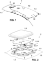
- Figure 1 shows a headliner (1) having a first side (1.1), configured for facing a vehicle interior in use and a second side (1.2) configured for facing a vehicle roof (8) in use.
- the headliner (1) is in use when it is assembled inside the vehicle interior and it covers the vehicle roof (8).
- the headliner (1) comprises a main surface (1.3) defined by the width and the length of the headliner (1) .
- the headliner (1) comprises an electronic module assembly (2) on the second side (1.2) of the headliner (1). In this way when the headliner (1) is in use, the electronic module assembly (2) is not seen in the vehicle interior by the passengers.
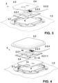
- the electronic module assembly (2) comprises:
- the frame (2.1) is the component which allows linking the electronic module assembly (2) with the headliner (1) in order to enable a modular assembly.
- the frame (2.1) allows the assembly of the electronic module assembly (2.2) onto the headliner (1) according to a mechanically stable way and to a precise position of both the electronic module assembly (2.2) as a whole, and each part forming the electronic module assembly (2.2) individually.
- the frame (2) can be formed by a single part or by several joined parts forming a frame for example according a square shape.
- the part or parts forming the frame (2.1) can be for example a L-shaped profile, U-shaped profile, C-shaped profile, etc.
- the frame (2.1) can be formed by a plastic or metal material.
- the frame (2.1) is connected to the second side (1.2) of the headliner (1) by first attaching means (3).
- the first attaching means (3) preferably comprises an adhesive, however other attaching means such as screws or clips can be used.
- the electronic module (2.2) comprising a printed circuit board (2.2.1), an electric wiring (2.2.2) and an electric connector (2.2.3).
- the printed circuit board (2.2.1) is arranged parallel to the main surface (1.3) of headliner (1). It comprises a first side (2.2.1.1) facing the headliner (1) and a second side (2.2.1.2) opposite to the first side (2.2.1.1).
- the printed circuit board (2.2.1) comprises several electronic components (10, 11, 12, 13) in order to perform the function for which it has been designed.
- the printed circuit board (2.2.1) comprises an antenna (10) placed on its second side (2.2.1.2) configured to communicate the vehicle with the vehicle exterior.
- the printed circuit board (2.2.1) is connected to the frame (2.1) by second attaching means (4).
- the second attaching means (4) can comprise for example clips, snap fit connectors, etc.
- the frame (2.1) can comprises a specific geometry which allows positioning and fixing the printed circuit board (2.2.1) in the frame (2.1).
- the electronic module (2.2) In order to electrically connect the printed circuit board (2.2.1) with the main vehicle electronics (not represented), the electronic module (2.2) also comprises an electric wiring (2.2.2) and an electric connector (2.2.3) placed on the printed circuit board (2.2.1).
- the frame (2.1) can comprise a specific geometry particularly designed to position and fix the electric connector (2.2.3) according to a position in which the connexion of the electric wiring (2.2.2) with the main vehicle electronics is facilitated.
- the electronic module (2.2) has a junction temperature T J . As it has been discussed above, this temperature is a specific value associated to each electronic module and it will depend on the particular electronic components forming part of said electronic module (2.2), and more particularly forming part of the printed circuit board (2.2.1) of said electronic module (2.2) .
- the junction temperature T J of the electronic module (2.2) corresponds with the junction temperature T J of one particular electronic component (10, 11, 12, 13) forming part of the electronic module (2.2) having the lowest junction temperature of all the electronic components (10, 11, 12, 13) forming the electronic module (2.2).
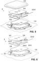
- the heat absorbing part (2.4) comprises a casing (2.4.1) which encloses the phase change material (2.4.2) in order to contain said phase change material (2.4.2) when it melts, that is, when it changes its phase, from solid to liquid.
- the casing (2.4.1) comprising a heat conductive material having a thermal conductivity higher than 0.1 W/m.K.
- the casing (2.4.1) is made of a plastic material.
- the casing (2.4.1) can be rigid or flexible.
- the casing (2.4.1) is configured in such a way that the heat absorbing part (2.4) is in contact, at least partly, with the printed circuit board (2.2.1) in order to favoured the heat transfer between both parts (2.2.1, 2.4).
- This contact can be a direct contact in such a way that the heat absorbing part (2.4) directly contacts at least some of the electronic components (10, 11, 12, 13) forming the printed circuit board (2.2.1), or can be an indirect contact in such a way that an additional element, such as a metallic component is arranged between the heat absorbing part (2.4) and the printed circuit board (2.2.1) in order to improve the heat transfer between both components (2.4, 2.2.1).
- the phase change material (2.4.2) of the invention is a liquid-solid phase change material. In the solid phase, it absorbs large amounts of heat until all the material is melted, that is, until it is transformed to the liquid phase. When the temperature around the printed circuit board (2.2.1) falls, the phase change material (2.4.2) solidifies, releasing its stored latent heat.
- the phase change material (2.4.2) has a melting point in the range between 70% of the junction temperature T J of the electronic module (2.2) and 105% of the junction temperature T J of the electronic module (2.2).
- the heat absorbing part (2.4) is arranged on the first side (2.2.1.1) of the printed circuit board (2.2.1).
- the heat absorbing part (2.4) is arranged on the second side (2.2.1.2) of the printed circuit board (2.2.1).
- the heat absorbing part (2.4) is arranged on the second side (2.2.1.2) of the printed circuit board (2.2.1) and a further heat absorbing part (2.5) is arranged in contact with the first side (2.2.1.1) of the printed circuit board (2.2.1).
- the further heat absorbing part (2.5) comprises the same technical features, such as the heat absorbing part (2.4) above described. Therefore, it comprises a further casing (2.5.1) comprising a heat conductive material having a thermal conductivity higher than 0.1 W/m.K, and a further phase change material (2.5.2) having a melting point in the range between 70% of the junction temperature T J and 105% of the junction temperature T J of the electronic module (2.2).
- Both, the heat absorbing part (2.4) and the further heat absorbing part (2.5) can be attached to the frame (2.1) by the forth attachment means (6).
- the mechanical protection cap (2.3) is arranged as the outer component of the electronic module assembly (2) and it covers the components forming the electronic module assembly (2) being between said mechanical protection cap (2.3) and the headliner (1) in such a way that they are mechanically protected from vibrations and impacts.
- the mechanical protection cap (2.3) comprises a thermal insulating material
- this part mitigates the heat coming from the solar radiation. In this way the heat received by the electronic module (2.2) is significantly reduced since this thermal insulating part is facing the vehicle roof (8).
- the thermal insulating material is the same material as the substrate (1.4) of the headliner (1).
- the headliner (1) comprises a substrate (1.4) and decorative layer (1.5), and the material of the substrate (1.4) is a thermal insulating material by itself, the scrap material, for example took from an opening provided on the substrate (1.4) for mounting a light console, is used to configure the mechanical protection cap (2.3).
- the mechanical protection cap (2.3) comprises the heat absorbing part (2.4).
- the same part is able to perform at least the main function of the mechanical protection cap (2.3) and the main function of the heat absorbing part (2.4).
- the casing (2.4.1) which encloses the phase change material (2.4.2) can be formed by a rigid material which is able to protect mechanically the rest of the parts forming the electronic module assembly (2).
- the mechanical protection cap (2.3) is connected to the frame (2.1) by third attachment means (5).
- the third attaching means (5) can be clips, screws or adhesive.
- the particular configuration of the third attaching means (5) will depend on the weight of the electric module assembly (2) and its electronic performance.
- the frame (2.1) comprises fifth attachment means (7) configured to attach the frame (2.1) to a vehicle roof (8).
- the present invention also relates to a vehicle roof assembly (80) comprising:
- the roof sheet (8.1) is a metal sheet, as it is shown in figure 8 , it can comprise an opening (8.1.1) facing the electronic module assembly (2).
- the opening (8.1.1) is covered by a plastic cap (9).
- the plastic cap (9) is arranged above the electronic module assembly (2).
- the electronic module assembly (2) is additionally attached to the vehicle roof (8).
- the electronic module assembly (2) can be attached to the vehicle roof (8) by fifth attachment means (7) configured to attach the frame (2.1) to the vehicle roof (6) according to any of the particular cases described in the previous paragraph.
- the electronic module (2.2), and particularly the printed circuit board (2.2.1), comprises an antenna (10) placed on its second side (2.2.1.2) configured to communicate the vehicle with the vehicle exterior.
- this particular case can be combined with a roof sheet (8.1) made of non-metallic materials, or in the case in which the roof sheet (8.1) is made of a metallic material, an opening (8.1.1) covered by a plastic cap (9) is arranged facing the electronic module assembly (2).
Landscapes
- Engineering & Computer Science (AREA)
- Remote Sensing (AREA)
- Mechanical Engineering (AREA)
- Vehicle Interior And Exterior Ornaments, Soundproofing, And Insulation (AREA)
- Support Of Aerials (AREA)
- Body Structure For Vehicles (AREA)
- Cooling Or The Like Of Electrical Apparatus (AREA)
Claims (14)
- Dachhimmel (1) mit elektronischer Modulanordnung (2) für Fahrzeuge umfassend:• einen Dachhimmel (1), der eine erste Seite (1.1), die gestaltet ist, um in Gebrauch einem Fahrzeuginnenraum zugewandt zu sein, und eine zweite Seite (1.2) umfasst, die gestaltet ist, um in Gebrauch einem Fahrzeugdach zugewandt zu sein, wobei der Dachhimmel (1) eine Hauptfläche (1.3) umfasst,• eine elektronische Modulanordnung (2) einschließlich:o eines Rahmens (2.1), der durch ein erstes Befestigungsmittel (3) mit der zweiten Seite (1.2) des Dachhimmels (1) verbunden ist,o eines elektronischen Moduls (2.2) umfassend:▪ eine mit dem Rahmen (2.1) durch ein zweites Befestigungsmittel (4) verbundene Leiterplatte (2.2.1), wobei die Leiterplatte (2.2.1) parallel zur Hauptfläche (1.3) des Dachhimmels (1) angeordnet ist und wobei die Leiterplatte (2.2.1) eine dem Dachhimmel (1) zugewandte erste Seite (2.2.1.1) und eine der ersten Seite (2.2.1.1) entgegengesetzte zweite Seite (2.2.1.2) umfasst,▪ eine elektrische Verdrahtung (2.2.2) und ein elektrisches Verbindungselement (2.2.3), das gestaltet ist, um die Leiterplatte (2.2.1) mit einer Hauptfahrzeugelektronik zu verbinden,wobei das Elektronikmodul (2.2) eine Sperrschichttemperatur TJ aufweist,o einen wärmeabsorbierenden Teil (2.4), der ein Gehäuse (2.4.1) umfasst, das ein wärmeleitendes Material mit einer Wärmeleitfähigkeit von über 0,1 W/m.K und ein Phasenwechselmaterial (2.4.2) mit einem Schmelzpunkt im Bereich zwischen 70 % der Sperrschichttemperatur TJ und 105 % der Sperrschichttemperatur TJ umfasst, wobei der wärmeabsorbierende Teil (2.4) mit der Leiterplatte (2.2.1) in Kontakt steht und wobei das Gehäuse (2.4.1) das Phasenwechselmaterial (2.4.2) umschließt,∘ eine als äußere Komponente der elektronischen Modulanordnung (2) angeordnete mechanische Schutzkappe (2.3), wobei die mechanische Schutzkappe (2.3) die die elektronische Modulanordnung (2) bildenden Komponenten zwischen der mechanischen Schutzkappe (2.3) und dem Dachhimmel (1) bedeckt.
- Dachhimmel (1) mit elektronischer Modulanordnung (2) für Fahrzeuge nach Anspruch 1, wobei die mechanische Schutzkappe (2.3) ein wärmeisolierendes Material umfasst.
- Dachhimmel (1) mit elektronischer Modulanordnung (2) für Fahrzeuge nach Anspruch 2, wobei der Dachhimmel (1) ein Substrat (1.4) und eine dekorative Schicht (1.5) umfasst und wobei das wärmeisolierende Material der mechanischen Schutzkappe (2.3) aus dem gleichen Material besteht wie das Substrat (1.4) des Dachhimmels (1).
- Dachhimmel (1) mit elektronischer Modulanordnung (2) für Fahrzeuge nach Anspruch 1, wobei der wärmeabsorbierende Teil (2.4) die mechanische Schutzkappe (2.3) umfasst.
- Dachhimmel (1) mit elektronischer Modulanordnung (2) für Fahrzeuge nach Anspruch 1, wobei der wärmeabsorbierende Teil (2.4) auf der ersten Seite (2.2.1.1) der Leiterplatte (2.2.1) angeordnet ist.
- Dachhimmel mit elektronischer Modulanordnung für Fahrzeuge nach Anspruch 1, wobei der wärmeabsorbierende Teil (2.3) auf der zweiten Seite (2.2.1.2) der Leiterplatte (2.2.1) angeordnet ist.
- Dachhimmel (1) mit elektronischer Modulanordnung (2) für Fahrzeuge nach Anspruch 1, wobei der wärmeabsorbierende Teil (2.4) auf der zweiten Seite (2.2.1.2) der Leiterplatte (2.2.1) angeordnet ist und ein weiterer wärmeabsorbierender Teil (2.5) mit der ersten Seite (2.2.1.1) der Leiterplatte (2.2.1) in Kontakt steht.
- Dachhimmel (1) mit elektronischer Modulanordnung (2) für Fahrzeuge nach Anspruch 7, wobei der weitere wärmeabsorbierende Teil (2.5) ein weiteres Gehäuse (2.5.1) umfasst, das ein wärmeleitendes Material mit einer Wärmeleitfähigkeit von über 0,1 W/m.K und ein weiteres Phasenwechselmaterial (2.5.2) mit einem Schmelzpunkt im Bereich zwischen 70 % der Sperrschichttemperatur (TJ) und 105 % der Sperrschichttemperatur (TJ) umfasst, wobei das Gehäuse (2.5.1) das weitere Phasenwechselmaterial (2.5.2) umschließt.
- Dachhimmel (1) mit elektronischer Modulanordnung (2) für Fahrzeuge nach einem der vorhergehenden Ansprüche, wobei die mechanische Schutzkappe (2.3) durch ein drittes Befestigungsmittel (5) mit dem Rahmen (2.1) verbunden ist.
- Dachhimmel (1) mit elektronischer Modulanordnung (2) für Fahrzeuge nach einem der vorhergehenden Ansprüche, wobei der Rahmen (2.1) ein fünftes Befestigungsmittel (7) umfasst, das gestaltet ist, um den Rahmen (2.1) an einem Fahrzeugdach (8) zu befestigen.
- Fahrzeugdachanordnung (80) umfassend:ein Fahrzeugdach (8),einen Dachhimmel (1) mit elektronischer Modulanordnung (2) für Fahrzeuge nach einem der vorhergehenden Ansprüche.
- Fahrzeugdachanordnung (80) nach Anspruch 11, wobei das Fahrzeugdach (8) ein Dachblech (8.1) aus Metall umfasst und das Dachblech (8.1) eine Dachöffnung (8.1.1) umfasst, die durch eine Kunststoffkappe (9) abgedeckt ist, die oberhalb der Elektronikmodulanordnung (2) angeordnet ist, wenn sich die Fahrzeugdachanordnung (80) in Gebrauch befindet.
- Fahrzeugdachanordnung (80) nach Anspruch 12, wobei die Elektronikmodulanordnung (2) um die Dachöffnung (8.1.1) herum an der Fahrzeugdachplatte (8.1) befestigt ist oder die Elektronikmodulanordnung (2) an der Kunststoffkappe (9) befestigt ist oder die Elektronikanordnung (2) an beiden Teilen befestigt ist.
- Fahrzeugdachanordnung (80) nach einem der Ansprüche 12 oder 13, wobei das elektronische Modul (2.2) eine Antenne (10) umfasst, die gestaltet ist, um die Fahrzeugkommunikation mit der Fahrzeugaußenseite zu verbinden, und wobei die Antenne (10) auf der zweiten Seite (2.2.1.2) der Leiterplatte (2.2.1) angeordnet ist.
Applications Claiming Priority (1)
| Application Number | Priority Date | Filing Date | Title |
|---|---|---|---|
| PCT/ES2019/070207 WO2020193818A1 (es) | 2019-03-27 | 2019-03-27 | Guarnecido de techo con conjunto de módulo electrónico para vehículos y conjunto de techo de vehículo comprendiendo dicho guarnecido |
Publications (2)
| Publication Number | Publication Date |
|---|---|
| EP3952020A1 EP3952020A1 (de) | 2022-02-09 |
| EP3952020B1 true EP3952020B1 (de) | 2023-06-14 |
Family
ID=66379937
Family Applications (1)
| Application Number | Title | Priority Date | Filing Date |
|---|---|---|---|
| EP19721328.3A Active EP3952020B1 (de) | 2019-03-27 | 2019-03-27 | Guarnecido de techo con conjunto de módulo electrónico para vehículos y conjunto de techo de vehículo comprendiendo dicho guarnecido |
Country Status (3)
| Country | Link |
|---|---|
| EP (1) | EP3952020B1 (de) |
| ES (1) | ES2950132T3 (de) |
| WO (1) | WO2020193818A1 (de) |
Families Citing this family (3)
| Publication number | Priority date | Publication date | Assignee | Title |
|---|---|---|---|---|
| FR3115501A1 (fr) * | 2020-10-27 | 2022-04-29 | Psa Automobiles Sa | Protection thermique passive par une grille d’aération d’un boitier de connectivité |
| FR3115500B1 (fr) * | 2020-10-27 | 2022-09-09 | Psa Automobiles Sa | Protection thermique passive par une mousse isolante d’un boitier de connectivité |
| CN113997870B (zh) * | 2021-10-29 | 2023-09-19 | 浙江极氪智能科技有限公司 | 一种车载通信模块总成装置、车身顶盖和车辆 |
Family Cites Families (4)
| Publication number | Priority date | Publication date | Assignee | Title |
|---|---|---|---|---|
| US6118410A (en) * | 1999-07-29 | 2000-09-12 | General Motors Corporation | Automobile roof antenna shelf |
| JP4515929B2 (ja) * | 2004-01-29 | 2010-08-04 | 株式会社日本自動車部品総合研究所 | 車両用オーバヘッドモジュール |
| DE102010039709A1 (de) | 2010-08-24 | 2012-01-19 | Continental Automotive Gmbh | Antennenmodul für ein Fahrzeug |
| WO2017178384A1 (fr) * | 2016-04-12 | 2017-10-19 | Valeo Comfort And Driving Assistance | Module d'antenne(s) pour véhicule automobile comprenant une feuille métallique |
-
2019
- 2019-03-27 WO PCT/ES2019/070207 patent/WO2020193818A1/es not_active Ceased
- 2019-03-27 ES ES19721328T patent/ES2950132T3/es active Active
- 2019-03-27 EP EP19721328.3A patent/EP3952020B1/de active Active
Also Published As
| Publication number | Publication date |
|---|---|
| WO2020193818A1 (es) | 2020-10-01 |
| ES2950132T3 (es) | 2023-10-05 |
| EP3952020A1 (de) | 2022-02-09 |
Similar Documents
| Publication | Publication Date | Title |
|---|---|---|
| US11489249B2 (en) | Vehicular communication system | |
| EP3952020B1 (de) | Guarnecido de techo con conjunto de módulo electrónico para vehículos y conjunto de techo de vehículo comprendiendo dicho guarnecido | |
| KR101158629B1 (ko) | 전자 제어 장치 | |
| EP1388465B1 (de) | Elektrische Steuereinheit | |
| JP2006303106A (ja) | 電子回路装置 | |
| JP2005117887A (ja) | 車載用回路ユニットの取付構造及び車載用回路ユニット | |
| JP2012079741A (ja) | 電子制御ユニット | |
| JP4387314B2 (ja) | 電気接続箱 | |
| JP5343989B2 (ja) | 電子制御装置 | |
| CN106061196B (zh) | 电子控制单元 | |
| JP2020195124A (ja) | 電子装置 | |
| JP2016213375A (ja) | 放熱基板及びこれを収納する放熱ケース。 | |
| JP4732789B2 (ja) | スイッチングユニット | |
| US9960584B2 (en) | Electrical junction box | |
| JP5846824B2 (ja) | 電動パワーステアリングコントロールユニット | |
| JP2017027994A (ja) | 放熱基板及びこれを収納する放熱ケース。 | |
| JP2016157715A (ja) | 放熱基板及びこれを収納する放熱ケース。 | |
| JP4783054B2 (ja) | スイッチングユニット | |
| JP2006271132A (ja) | 自動車用電気接続箱の固定構造 | |
| JP2010173645A (ja) | 車載用回路ユニットの取付構造及び前記車載用回路ユニットが組み込まれた電気接続箱 | |
| EP0952764B1 (de) | Widerstand für einen Steuerverstärker und Steuervertärker mit diesem Widerstand | |
| CN223843990U (zh) | 一种域控制器及车辆 | |
| JP4653541B2 (ja) | スイッチングユニット | |
| JP4524667B2 (ja) | 電気接続箱 | |
| JP2017001412A (ja) | 電子部品の放熱構造 |
Legal Events
| Date | Code | Title | Description |
|---|---|---|---|
| STAA | Information on the status of an ep patent application or granted ep patent |
Free format text: STATUS: UNKNOWN |
|
| STAA | Information on the status of an ep patent application or granted ep patent |
Free format text: STATUS: THE INTERNATIONAL PUBLICATION HAS BEEN MADE |
|
| PUAI | Public reference made under article 153(3) epc to a published international application that has entered the european phase |
Free format text: ORIGINAL CODE: 0009012 |
|
| STAA | Information on the status of an ep patent application or granted ep patent |
Free format text: STATUS: REQUEST FOR EXAMINATION WAS MADE |
|
| 17P | Request for examination filed |
Effective date: 20211022 |
|
| AK | Designated contracting states |
Kind code of ref document: A1 Designated state(s): AL AT BE BG CH CY CZ DE DK EE ES FI FR GB GR HR HU IE IS IT LI LT LU LV MC MK MT NL NO PL PT RO RS SE SI SK SM TR |
|
| DAV | Request for validation of the european patent (deleted) | ||
| DAX | Request for extension of the european patent (deleted) | ||
| GRAP | Despatch of communication of intention to grant a patent |
Free format text: ORIGINAL CODE: EPIDOSNIGR1 |
|
| STAA | Information on the status of an ep patent application or granted ep patent |
Free format text: STATUS: GRANT OF PATENT IS INTENDED |
|
| INTG | Intention to grant announced |
Effective date: 20230110 |
|
| GRAS | Grant fee paid |
Free format text: ORIGINAL CODE: EPIDOSNIGR3 |
|
| GRAA | (expected) grant |
Free format text: ORIGINAL CODE: 0009210 |
|
| STAA | Information on the status of an ep patent application or granted ep patent |
Free format text: STATUS: THE PATENT HAS BEEN GRANTED |
|
| AK | Designated contracting states |
Kind code of ref document: B1 Designated state(s): AL AT BE BG CH CY CZ DE DK EE ES FI FR GB GR HR HU IE IS IT LI LT LU LV MC MK MT NL NO PL PT RO RS SE SI SK SM TR |
|
| REG | Reference to a national code |
Ref country code: CH Ref legal event code: EP |
|
| REG | Reference to a national code |
Ref country code: DE Ref legal event code: R096 Ref document number: 602019031012 Country of ref document: DE |
|
| REG | Reference to a national code |
Ref country code: AT Ref legal event code: REF Ref document number: 1579918 Country of ref document: AT Kind code of ref document: T Effective date: 20230715 |
|
| REG | Reference to a national code |
Ref country code: ES Ref legal event code: FG2A Ref document number: 2950132 Country of ref document: ES Kind code of ref document: T3 Effective date: 20231005 |
|
| REG | Reference to a national code |
Ref country code: LT Ref legal event code: MG9D |
|
| REG | Reference to a national code |
Ref country code: NL Ref legal event code: MP Effective date: 20230614 |
|
| PG25 | Lapsed in a contracting state [announced via postgrant information from national office to epo] |
Ref country code: SE Free format text: LAPSE BECAUSE OF FAILURE TO SUBMIT A TRANSLATION OF THE DESCRIPTION OR TO PAY THE FEE WITHIN THE PRESCRIBED TIME-LIMIT Effective date: 20230614 Ref country code: NO Free format text: LAPSE BECAUSE OF FAILURE TO SUBMIT A TRANSLATION OF THE DESCRIPTION OR TO PAY THE FEE WITHIN THE PRESCRIBED TIME-LIMIT Effective date: 20230914 |
|
| REG | Reference to a national code |
Ref country code: AT Ref legal event code: MK05 Ref document number: 1579918 Country of ref document: AT Kind code of ref document: T Effective date: 20230614 |
|
| PG25 | Lapsed in a contracting state [announced via postgrant information from national office to epo] |
Ref country code: RS Free format text: LAPSE BECAUSE OF FAILURE TO SUBMIT A TRANSLATION OF THE DESCRIPTION OR TO PAY THE FEE WITHIN THE PRESCRIBED TIME-LIMIT Effective date: 20230614 Ref country code: NL Free format text: LAPSE BECAUSE OF FAILURE TO SUBMIT A TRANSLATION OF THE DESCRIPTION OR TO PAY THE FEE WITHIN THE PRESCRIBED TIME-LIMIT Effective date: 20230614 Ref country code: LV Free format text: LAPSE BECAUSE OF FAILURE TO SUBMIT A TRANSLATION OF THE DESCRIPTION OR TO PAY THE FEE WITHIN THE PRESCRIBED TIME-LIMIT Effective date: 20230614 Ref country code: LT Free format text: LAPSE BECAUSE OF FAILURE TO SUBMIT A TRANSLATION OF THE DESCRIPTION OR TO PAY THE FEE WITHIN THE PRESCRIBED TIME-LIMIT Effective date: 20230614 Ref country code: HR Free format text: LAPSE BECAUSE OF FAILURE TO SUBMIT A TRANSLATION OF THE DESCRIPTION OR TO PAY THE FEE WITHIN THE PRESCRIBED TIME-LIMIT Effective date: 20230614 Ref country code: GR Free format text: LAPSE BECAUSE OF FAILURE TO SUBMIT A TRANSLATION OF THE DESCRIPTION OR TO PAY THE FEE WITHIN THE PRESCRIBED TIME-LIMIT Effective date: 20230915 |
|
| PG25 | Lapsed in a contracting state [announced via postgrant information from national office to epo] |
Ref country code: FI Free format text: LAPSE BECAUSE OF FAILURE TO SUBMIT A TRANSLATION OF THE DESCRIPTION OR TO PAY THE FEE WITHIN THE PRESCRIBED TIME-LIMIT Effective date: 20230614 |
|
| PG25 | Lapsed in a contracting state [announced via postgrant information from national office to epo] |
Ref country code: SK Free format text: LAPSE BECAUSE OF FAILURE TO SUBMIT A TRANSLATION OF THE DESCRIPTION OR TO PAY THE FEE WITHIN THE PRESCRIBED TIME-LIMIT Effective date: 20230614 |
|
| PG25 | Lapsed in a contracting state [announced via postgrant information from national office to epo] |
Ref country code: IS Free format text: LAPSE BECAUSE OF FAILURE TO SUBMIT A TRANSLATION OF THE DESCRIPTION OR TO PAY THE FEE WITHIN THE PRESCRIBED TIME-LIMIT Effective date: 20231014 |
|
| PG25 | Lapsed in a contracting state [announced via postgrant information from national office to epo] |
Ref country code: SM Free format text: LAPSE BECAUSE OF FAILURE TO SUBMIT A TRANSLATION OF THE DESCRIPTION OR TO PAY THE FEE WITHIN THE PRESCRIBED TIME-LIMIT Effective date: 20230614 Ref country code: SK Free format text: LAPSE BECAUSE OF FAILURE TO SUBMIT A TRANSLATION OF THE DESCRIPTION OR TO PAY THE FEE WITHIN THE PRESCRIBED TIME-LIMIT Effective date: 20230614 Ref country code: RO Free format text: LAPSE BECAUSE OF FAILURE TO SUBMIT A TRANSLATION OF THE DESCRIPTION OR TO PAY THE FEE WITHIN THE PRESCRIBED TIME-LIMIT Effective date: 20230614 Ref country code: PT Free format text: LAPSE BECAUSE OF FAILURE TO SUBMIT A TRANSLATION OF THE DESCRIPTION OR TO PAY THE FEE WITHIN THE PRESCRIBED TIME-LIMIT Effective date: 20231016 Ref country code: IS Free format text: LAPSE BECAUSE OF FAILURE TO SUBMIT A TRANSLATION OF THE DESCRIPTION OR TO PAY THE FEE WITHIN THE PRESCRIBED TIME-LIMIT Effective date: 20231014 Ref country code: EE Free format text: LAPSE BECAUSE OF FAILURE TO SUBMIT A TRANSLATION OF THE DESCRIPTION OR TO PAY THE FEE WITHIN THE PRESCRIBED TIME-LIMIT Effective date: 20230614 Ref country code: CZ Free format text: LAPSE BECAUSE OF FAILURE TO SUBMIT A TRANSLATION OF THE DESCRIPTION OR TO PAY THE FEE WITHIN THE PRESCRIBED TIME-LIMIT Effective date: 20230614 Ref country code: AT Free format text: LAPSE BECAUSE OF FAILURE TO SUBMIT A TRANSLATION OF THE DESCRIPTION OR TO PAY THE FEE WITHIN THE PRESCRIBED TIME-LIMIT Effective date: 20230614 |
|
| PG25 | Lapsed in a contracting state [announced via postgrant information from national office to epo] |
Ref country code: PL Free format text: LAPSE BECAUSE OF FAILURE TO SUBMIT A TRANSLATION OF THE DESCRIPTION OR TO PAY THE FEE WITHIN THE PRESCRIBED TIME-LIMIT Effective date: 20230614 |
|
| REG | Reference to a national code |
Ref country code: DE Ref legal event code: R097 Ref document number: 602019031012 Country of ref document: DE |
|
| PLBE | No opposition filed within time limit |
Free format text: ORIGINAL CODE: 0009261 |
|
| STAA | Information on the status of an ep patent application or granted ep patent |
Free format text: STATUS: NO OPPOSITION FILED WITHIN TIME LIMIT |
|
| PG25 | Lapsed in a contracting state [announced via postgrant information from national office to epo] |
Ref country code: DK Free format text: LAPSE BECAUSE OF FAILURE TO SUBMIT A TRANSLATION OF THE DESCRIPTION OR TO PAY THE FEE WITHIN THE PRESCRIBED TIME-LIMIT Effective date: 20230614 |
|
| PG25 | Lapsed in a contracting state [announced via postgrant information from national office to epo] |
Ref country code: SI Free format text: LAPSE BECAUSE OF FAILURE TO SUBMIT A TRANSLATION OF THE DESCRIPTION OR TO PAY THE FEE WITHIN THE PRESCRIBED TIME-LIMIT Effective date: 20230614 |
|
| 26N | No opposition filed |
Effective date: 20240315 |
|
| PG25 | Lapsed in a contracting state [announced via postgrant information from national office to epo] |
Ref country code: SI Free format text: LAPSE BECAUSE OF FAILURE TO SUBMIT A TRANSLATION OF THE DESCRIPTION OR TO PAY THE FEE WITHIN THE PRESCRIBED TIME-LIMIT Effective date: 20230614 Ref country code: IT Free format text: LAPSE BECAUSE OF FAILURE TO SUBMIT A TRANSLATION OF THE DESCRIPTION OR TO PAY THE FEE WITHIN THE PRESCRIBED TIME-LIMIT Effective date: 20230614 |
|
| REG | Reference to a national code |
Ref country code: CH Ref legal event code: PL |
|
| PG25 | Lapsed in a contracting state [announced via postgrant information from national office to epo] |
Ref country code: BG Free format text: LAPSE BECAUSE OF FAILURE TO SUBMIT A TRANSLATION OF THE DESCRIPTION OR TO PAY THE FEE WITHIN THE PRESCRIBED TIME-LIMIT Effective date: 20230614 |
|
| PG25 | Lapsed in a contracting state [announced via postgrant information from national office to epo] |
Ref country code: LU Free format text: LAPSE BECAUSE OF NON-PAYMENT OF DUE FEES Effective date: 20240327 |
|
| PG25 | Lapsed in a contracting state [announced via postgrant information from national office to epo] |
Ref country code: MC Free format text: LAPSE BECAUSE OF FAILURE TO SUBMIT A TRANSLATION OF THE DESCRIPTION OR TO PAY THE FEE WITHIN THE PRESCRIBED TIME-LIMIT Effective date: 20230614 |
|
| GBPC | Gb: european patent ceased through non-payment of renewal fee |
Effective date: 20240327 |
|
| PG25 | Lapsed in a contracting state [announced via postgrant information from national office to epo] |
Ref country code: MC Free format text: LAPSE BECAUSE OF FAILURE TO SUBMIT A TRANSLATION OF THE DESCRIPTION OR TO PAY THE FEE WITHIN THE PRESCRIBED TIME-LIMIT Effective date: 20230614 Ref country code: LU Free format text: LAPSE BECAUSE OF NON-PAYMENT OF DUE FEES Effective date: 20240327 Ref country code: BG Free format text: LAPSE BECAUSE OF FAILURE TO SUBMIT A TRANSLATION OF THE DESCRIPTION OR TO PAY THE FEE WITHIN THE PRESCRIBED TIME-LIMIT Effective date: 20230614 |
|
| REG | Reference to a national code |
Ref country code: BE Ref legal event code: MM Effective date: 20240331 |
|
| PG25 | Lapsed in a contracting state [announced via postgrant information from national office to epo] |
Ref country code: BE Free format text: LAPSE BECAUSE OF NON-PAYMENT OF DUE FEES Effective date: 20240331 |
|
| PG25 | Lapsed in a contracting state [announced via postgrant information from national office to epo] |
Ref country code: GB Free format text: LAPSE BECAUSE OF NON-PAYMENT OF DUE FEES Effective date: 20240327 |
|
| PG25 | Lapsed in a contracting state [announced via postgrant information from national office to epo] |
Ref country code: IE Free format text: LAPSE BECAUSE OF NON-PAYMENT OF DUE FEES Effective date: 20240327 |
|
| PG25 | Lapsed in a contracting state [announced via postgrant information from national office to epo] |
Ref country code: IE Free format text: LAPSE BECAUSE OF NON-PAYMENT OF DUE FEES Effective date: 20240327 Ref country code: GB Free format text: LAPSE BECAUSE OF NON-PAYMENT OF DUE FEES Effective date: 20240327 Ref country code: BE Free format text: LAPSE BECAUSE OF NON-PAYMENT OF DUE FEES Effective date: 20240331 Ref country code: CH Free format text: LAPSE BECAUSE OF NON-PAYMENT OF DUE FEES Effective date: 20240331 |
|
| PGFP | Annual fee paid to national office [announced via postgrant information from national office to epo] |
Ref country code: DE Payment date: 20250328 Year of fee payment: 7 |
|
| PGFP | Annual fee paid to national office [announced via postgrant information from national office to epo] |
Ref country code: FR Payment date: 20250321 Year of fee payment: 7 |
|
| PGFP | Annual fee paid to national office [announced via postgrant information from national office to epo] |
Ref country code: ES Payment date: 20250401 Year of fee payment: 7 |
|
| PG25 | Lapsed in a contracting state [announced via postgrant information from national office to epo] |
Ref country code: CY Free format text: LAPSE BECAUSE OF FAILURE TO SUBMIT A TRANSLATION OF THE DESCRIPTION OR TO PAY THE FEE WITHIN THE PRESCRIBED TIME-LIMIT; INVALID AB INITIO Effective date: 20190327 |
|
| P01 | Opt-out of the competence of the unified patent court (upc) registered |
Free format text: CASE NUMBER: UPC_APP_0958_3952020/2025 Effective date: 20250724 |
|
| PG25 | Lapsed in a contracting state [announced via postgrant information from national office to epo] |
Ref country code: HU Free format text: LAPSE BECAUSE OF FAILURE TO SUBMIT A TRANSLATION OF THE DESCRIPTION OR TO PAY THE FEE WITHIN THE PRESCRIBED TIME-LIMIT; INVALID AB INITIO Effective date: 20190327 |
|
| PG25 | Lapsed in a contracting state [announced via postgrant information from national office to epo] |
Ref country code: TR Free format text: LAPSE BECAUSE OF FAILURE TO SUBMIT A TRANSLATION OF THE DESCRIPTION OR TO PAY THE FEE WITHIN THE PRESCRIBED TIME-LIMIT Effective date: 20230614 |