EP3951284A1 - Kältekreislaufvorrichtung - Google Patents
Kältekreislaufvorrichtung Download PDFInfo
- Publication number
- EP3951284A1 EP3951284A1 EP19923242.2A EP19923242A EP3951284A1 EP 3951284 A1 EP3951284 A1 EP 3951284A1 EP 19923242 A EP19923242 A EP 19923242A EP 3951284 A1 EP3951284 A1 EP 3951284A1
- Authority
- EP
- European Patent Office
- Prior art keywords
- heat exchanger
- refrigerant
- port
- circulation direction
- node
- Prior art date
- Legal status (The legal status is an assumption and is not a legal conclusion. Google has not performed a legal analysis and makes no representation as to the accuracy of the status listed.)
- Withdrawn
Links
Images


Classifications
-
- F—MECHANICAL ENGINEERING; LIGHTING; HEATING; WEAPONS; BLASTING
- F25—REFRIGERATION OR COOLING; COMBINED HEATING AND REFRIGERATION SYSTEMS; HEAT PUMP SYSTEMS; MANUFACTURE OR STORAGE OF ICE; LIQUEFACTION SOLIDIFICATION OF GASES
- F25B—REFRIGERATION MACHINES, PLANTS OR SYSTEMS; COMBINED HEATING AND REFRIGERATION SYSTEMS; HEAT PUMP SYSTEMS
- F25B13/00—Compression machines, plants or systems, with reversible cycle
-
- F—MECHANICAL ENGINEERING; LIGHTING; HEATING; WEAPONS; BLASTING
- F25—REFRIGERATION OR COOLING; COMBINED HEATING AND REFRIGERATION SYSTEMS; HEAT PUMP SYSTEMS; MANUFACTURE OR STORAGE OF ICE; LIQUEFACTION SOLIDIFICATION OF GASES
- F25B—REFRIGERATION MACHINES, PLANTS OR SYSTEMS; COMBINED HEATING AND REFRIGERATION SYSTEMS; HEAT PUMP SYSTEMS
- F25B40/00—Subcoolers, desuperheaters or superheaters
-
- F—MECHANICAL ENGINEERING; LIGHTING; HEATING; WEAPONS; BLASTING
- F25—REFRIGERATION OR COOLING; COMBINED HEATING AND REFRIGERATION SYSTEMS; HEAT PUMP SYSTEMS; MANUFACTURE OR STORAGE OF ICE; LIQUEFACTION SOLIDIFICATION OF GASES
- F25B—REFRIGERATION MACHINES, PLANTS OR SYSTEMS; COMBINED HEATING AND REFRIGERATION SYSTEMS; HEAT PUMP SYSTEMS
- F25B41/00—Fluid-circulation arrangements
- F25B41/20—Disposition of valves, e.g. of on-off valves or flow control valves
-
- F—MECHANICAL ENGINEERING; LIGHTING; HEATING; WEAPONS; BLASTING
- F25—REFRIGERATION OR COOLING; COMBINED HEATING AND REFRIGERATION SYSTEMS; HEAT PUMP SYSTEMS; MANUFACTURE OR STORAGE OF ICE; LIQUEFACTION SOLIDIFICATION OF GASES
- F25B—REFRIGERATION MACHINES, PLANTS OR SYSTEMS; COMBINED HEATING AND REFRIGERATION SYSTEMS; HEAT PUMP SYSTEMS
- F25B41/00—Fluid-circulation arrangements
- F25B41/30—Expansion means; Dispositions thereof
-
- F—MECHANICAL ENGINEERING; LIGHTING; HEATING; WEAPONS; BLASTING
- F25—REFRIGERATION OR COOLING; COMBINED HEATING AND REFRIGERATION SYSTEMS; HEAT PUMP SYSTEMS; MANUFACTURE OR STORAGE OF ICE; LIQUEFACTION SOLIDIFICATION OF GASES
- F25B—REFRIGERATION MACHINES, PLANTS OR SYSTEMS; COMBINED HEATING AND REFRIGERATION SYSTEMS; HEAT PUMP SYSTEMS
- F25B49/00—Arrangement or mounting of control or safety devices
- F25B49/02—Arrangement or mounting of control or safety devices for compression type machines, plants or systems
-
- F—MECHANICAL ENGINEERING; LIGHTING; HEATING; WEAPONS; BLASTING
- F25—REFRIGERATION OR COOLING; COMBINED HEATING AND REFRIGERATION SYSTEMS; HEAT PUMP SYSTEMS; MANUFACTURE OR STORAGE OF ICE; LIQUEFACTION SOLIDIFICATION OF GASES
- F25B—REFRIGERATION MACHINES, PLANTS OR SYSTEMS; COMBINED HEATING AND REFRIGERATION SYSTEMS; HEAT PUMP SYSTEMS
- F25B2313/00—Compression machines, plants or systems with reversible cycle not otherwise provided for
- F25B2313/006—Compression machines, plants or systems with reversible cycle not otherwise provided for two pipes connecting the outdoor side to the indoor side with multiple indoor units
-
- F—MECHANICAL ENGINEERING; LIGHTING; HEATING; WEAPONS; BLASTING
- F25—REFRIGERATION OR COOLING; COMBINED HEATING AND REFRIGERATION SYSTEMS; HEAT PUMP SYSTEMS; MANUFACTURE OR STORAGE OF ICE; LIQUEFACTION SOLIDIFICATION OF GASES
- F25B—REFRIGERATION MACHINES, PLANTS OR SYSTEMS; COMBINED HEATING AND REFRIGERATION SYSTEMS; HEAT PUMP SYSTEMS
- F25B2313/00—Compression machines, plants or systems with reversible cycle not otherwise provided for
- F25B2313/027—Compression machines, plants or systems with reversible cycle not otherwise provided for characterised by the reversing means
- F25B2313/02741—Compression machines, plants or systems with reversible cycle not otherwise provided for characterised by the reversing means using one four-way valve
-
- F—MECHANICAL ENGINEERING; LIGHTING; HEATING; WEAPONS; BLASTING
- F25—REFRIGERATION OR COOLING; COMBINED HEATING AND REFRIGERATION SYSTEMS; HEAT PUMP SYSTEMS; MANUFACTURE OR STORAGE OF ICE; LIQUEFACTION SOLIDIFICATION OF GASES
- F25B—REFRIGERATION MACHINES, PLANTS OR SYSTEMS; COMBINED HEATING AND REFRIGERATION SYSTEMS; HEAT PUMP SYSTEMS
- F25B2400/00—General features or devices for refrigeration machines, plants or systems, combined heating and refrigeration systems or heat-pump systems, i.e. not limited to a particular subgroup of F25B
- F25B2400/04—Refrigeration circuit bypassing means
- F25B2400/0405—Refrigeration circuit bypassing means for the desuperheater
-
- F—MECHANICAL ENGINEERING; LIGHTING; HEATING; WEAPONS; BLASTING
- F25—REFRIGERATION OR COOLING; COMBINED HEATING AND REFRIGERATION SYSTEMS; HEAT PUMP SYSTEMS; MANUFACTURE OR STORAGE OF ICE; LIQUEFACTION SOLIDIFICATION OF GASES
- F25B—REFRIGERATION MACHINES, PLANTS OR SYSTEMS; COMBINED HEATING AND REFRIGERATION SYSTEMS; HEAT PUMP SYSTEMS
- F25B2400/00—General features or devices for refrigeration machines, plants or systems, combined heating and refrigeration systems or heat-pump systems, i.e. not limited to a particular subgroup of F25B
- F25B2400/04—Refrigeration circuit bypassing means
- F25B2400/0417—Refrigeration circuit bypassing means for the subcooler
-
- F—MECHANICAL ENGINEERING; LIGHTING; HEATING; WEAPONS; BLASTING
- F25—REFRIGERATION OR COOLING; COMBINED HEATING AND REFRIGERATION SYSTEMS; HEAT PUMP SYSTEMS; MANUFACTURE OR STORAGE OF ICE; LIQUEFACTION SOLIDIFICATION OF GASES
- F25B—REFRIGERATION MACHINES, PLANTS OR SYSTEMS; COMBINED HEATING AND REFRIGERATION SYSTEMS; HEAT PUMP SYSTEMS
- F25B2400/00—General features or devices for refrigeration machines, plants or systems, combined heating and refrigeration systems or heat-pump systems, i.e. not limited to a particular subgroup of F25B
- F25B2400/04—Refrigeration circuit bypassing means
- F25B2400/0419—Refrigeration circuit bypassing means for the superheater
-
- F—MECHANICAL ENGINEERING; LIGHTING; HEATING; WEAPONS; BLASTING
- F25—REFRIGERATION OR COOLING; COMBINED HEATING AND REFRIGERATION SYSTEMS; HEAT PUMP SYSTEMS; MANUFACTURE OR STORAGE OF ICE; LIQUEFACTION SOLIDIFICATION OF GASES
- F25B—REFRIGERATION MACHINES, PLANTS OR SYSTEMS; COMBINED HEATING AND REFRIGERATION SYSTEMS; HEAT PUMP SYSTEMS
- F25B2400/00—General features or devices for refrigeration machines, plants or systems, combined heating and refrigeration systems or heat-pump systems, i.e. not limited to a particular subgroup of F25B
- F25B2400/16—Receivers
-
- F—MECHANICAL ENGINEERING; LIGHTING; HEATING; WEAPONS; BLASTING
- F25—REFRIGERATION OR COOLING; COMBINED HEATING AND REFRIGERATION SYSTEMS; HEAT PUMP SYSTEMS; MANUFACTURE OR STORAGE OF ICE; LIQUEFACTION SOLIDIFICATION OF GASES
- F25B—REFRIGERATION MACHINES, PLANTS OR SYSTEMS; COMBINED HEATING AND REFRIGERATION SYSTEMS; HEAT PUMP SYSTEMS
- F25B2600/00—Control issues
- F25B2600/25—Control of valves
- F25B2600/2507—Flow-diverting valves
-
- F—MECHANICAL ENGINEERING; LIGHTING; HEATING; WEAPONS; BLASTING
- F25—REFRIGERATION OR COOLING; COMBINED HEATING AND REFRIGERATION SYSTEMS; HEAT PUMP SYSTEMS; MANUFACTURE OR STORAGE OF ICE; LIQUEFACTION SOLIDIFICATION OF GASES
- F25B—REFRIGERATION MACHINES, PLANTS OR SYSTEMS; COMBINED HEATING AND REFRIGERATION SYSTEMS; HEAT PUMP SYSTEMS
- F25B2600/00—Control issues
- F25B2600/25—Control of valves
- F25B2600/2513—Expansion valves
Definitions
- the present disclosure relates to a refrigeration cycle apparatus in which the circulation direction of refrigerant is switched between a first circulation direction and a second circulation direction opposite to the first circulation direction.
- Japanese Patent No. 6058145 discloses an air conditioning apparatus in which an indoor unit includes an expansion valve and an outdoor unit includes an expansion valve, and these two expansion valves are connected to each other via an extension pipe.
- the expansion valve of the indoor unit reduces the pressure of refrigerant to turn the refrigerant into a gas-liquid two-phase state, and the refrigerant in the gas-liquid two-phase state flows through the extension pipe.
- the expansion valve of the outdoor unit reduces the pressure of refrigerant to turn the refrigerant into a gas-liquid two-phase state, and the refrigerant in the gas-liquid two-phase state flows through the extension pipe.
- the refrigerant in the gas-liquid two-phase state (wet steam) flows through the extension pipe during both the heating operation and the cooling operation. Because the density of the wet steam is lower than the density of refrigerant in the liquid state (liquid refrigerant), the amount of refrigerant circulating through the air conditioning apparatus can be reduced.
- liquid refrigerant flows into one expansion valve, the expansion valve reduces the pressure of the refrigerant to turn the refrigerant into wet steam, and the wet steam flows into the other expansion valve, during both the heating operation and the cooling operation.
- the circulation direction of refrigerant can be switched like the above-identified air conditioning apparatus, it has to be assumed that both liquid refrigerant and wet steam may flow into each of the two expansion valves.
- the lower the density of refrigerant flowing into the expansion valve the higher the flow coefficient (Cv value) of the expansion valve should be.
- the maximum value of the Cv value of an expansion valve into which wet steam is to flow should be larger than the maximum value of the Cv value of an expansion valve into which only liquid refrigerant is to flow.
- the present disclosure has been made to solve the problems as described above, and its object is to suppress deterioration of the controllability for the refrigeration cycle apparatus.
- a circulation direction of refrigerant is switched between a first circulation direction and a second circulation direction opposite to the first circulation direction.
- the refrigeration cycle apparatus includes: a compressor; a first heat exchanger; a second heat exchanger; a third heat exchanger; a fourth heat exchanger; a first expansion valve; and a second expansion valve.
- the first circulation direction is a circulation direction in order of the compressor, the first heat exchanger, the first expansion valve, the third heat exchanger, the fourth heat exchanger, the second expansion valve, and the second heat exchanger.
- the refrigerant from the third heat exchanger exchanges heat with the refrigerant from the second heat exchanger in the fourth heat exchanger.
- a circulation direction of the refrigerant is the second circulation direction
- the refrigerant from the fourth heat exchanger exchanges heat with the refrigerant from the first heat exchanger in the third heat exchanger.
- the refrigerant from the third heat exchanger exchanges heat, in the fourth heat exchanger, with the refrigerant from the second heat exchanger and, when a circulation direction of the refrigerant is the second circulation direction, the refrigerant from the fourth heat exchanger exchanges heat, in the third heat exchanger, with the refrigerant from the first heat exchanger. Accordingly, deterioration of the controllability can be suppressed.
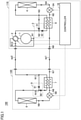
- Fig. 1 shows a functional configuration of an air conditioner 100 that is an example of a refrigeration cycle apparatus according to Embodiment 1, together with flow of refrigerant during a cooling operation.
- air conditioner 100 includes an outdoor unit 110 and an indoor unit 120. Outdoor unit 110 and indoor unit 120 are connected to each other by each of extension pipes ep1 and ep2. Air conditioner 100 performs air conditioning for an indoor space where indoor unit 120 is placed.
- Outdoor unit 110 includes a compressor 1, a four-way valve 2, a switch 3 (first switch), a heat exchanger 4 (first heat exchanger), an expansion valve 5A (first expansion valve), an internal heat exchanger 6 (third heat exchanger), and a controller 10.
- Indoor unit 120 includes an internal heat exchanger 7 (fourth heat exchanger), an expansion valve 5B (second expansion valve), a heat exchanger 8 (second heat exchanger), and a switch 9 (second switch). Expansion valves 5A and 5B have respective structures similar to each other. Controller 10 may alternatively be included in indoor unit 120, or placed separately from outdoor unit 110 and indoor unit 120.
- refrigerant circulates in a circulation direction (first circulation direction) in order of compressor 1, four-way valve 2, heat exchanger 4, expansion valve 5A, internal heat exchanger 6, internal heat exchanger 7, expansion valve 5B, heat exchanger 8, and four-way valve 2.
- Refrigerant flowing out of outdoor unit 110 flows into indoor unit 120 through extension pipe ep1.
- Refrigerant flowing out of indoor unit 120 flows into outdoor unit 110 through extension pipe ep2.
- heat exchanger 4 serves as a condenser and heat exchanger 8 serves as an evaporator.
- Switch 3 includes a check valve 31 (first check valve) and a check valve 32 (second check valve). Internal heat exchanger 6 is connected between an output port of check valve 31 and an input port of check valve 32. The output port of check valve 31 is connected to heat exchanger 4. During the cooling operation, an input port of check valve 31 communicates with a discharge port of compressor 1 through four-way valve 2. Refrigerant from four-way valve 2 flows through check valve 31 toward heat exchanger 4 without flowing through check valve 32. Namely, switch 3 directs refrigerant from compressor 1 to flow to heat exchanger 4 without flowing through internal heat exchanger 6. The pressure of refrigerant flowing out of check valve 31 is lower than the pressure of refrigerant flowing into check valve 31, because of a pressure loss due to check valve 31. Most of the refrigerant from check valve 31 therefore flows toward heat exchanger 4.
- Switch 9 includes a check valve 91 (third check valve) and a check valve 92 (fourth check valve).
- Internal heat exchanger 7 is connected between an input port of check valve 91 and an output port of check valve 92.
- An output port of check valve 91 is connected to heat exchanger 8 and an input port of check valve 92.
- switch 9 directs the refrigerant from heat exchanger 8 to flow through internal heat exchanger 7 to compressor 1.
- heat is exchanged between refrigerant from internal heat exchanger 6 and refrigerant from heat exchanger 8.
- the pressure of refrigerant flowing out of internal heat exchanger 7 is lower than the pressure of refrigerant flowing into check valve 92 because of a pressure loss due to check valve 92 and internal heat exchanger 7. Most of the refrigerant from internal heat exchanger 7 therefore flows toward four-way valve 2.
- a node N1 is a node through which refrigerant flowing from four-way valve 2 to compressor 1 passes.
- a node N2 is a node through which refrigerant flowing from compressor 1 to check valve 31 passes.
- a node N3 is a node through which refrigerant flowing from check valve 31 to heat exchanger 4 passes.
- a node N4 is a node through which refrigerant flowing from heat exchanger 4 to expansion valve 5A passes.
- a node N5 is a node through which refrigerant flowing from expansion valve 5A to internal heat exchanger 6 passes.
- a node N6 is a node through which refrigerant flowing from internal heat exchanger 6 to extension pipe ep1 passes.
- a node N7 is a node through which refrigerant flowing from extension pipe ep1 to internal heat exchanger 7 passes.
- a node N8 is a node through which refrigerant flowing from internal heat exchanger 7 to expansion valve 5B passes.
- a node N9 is a node through which refrigerant flowing from expansion valve 5B to heat exchanger 8 passes.
- a node N10 is a node through which refrigerant flowing from heat exchanger 8 to internal heat exchanger 7 passes.
- a node N11 is a node through which refrigerant flowing from internal heat exchanger 7 to extension pipe ep2 passes.
- a node N12 is a node through which refrigerant flowing from extension pipe ep2 to four-way valve 2 passes.
- Controller 10 controls the driving frequency of compressor 1 so as to control the amount of refrigerant discharged from compressor 1 per unit time, so that the temperature of the indoor space reaches a target temperature (set by a user, for example). Controller 10 controls the opening degree of expansion valve 5A and the opening degree of expansion valve 5B so that the pressure difference between refrigerant after being discharged from compressor 1 and before being reduced in pressure and the refrigerant after being reduced in pressure and before being sucked into compressor 1 has a value within a desired range. Expansion valve 5A and expansion valve 5B may be controlled so that the degree of superheat of refrigerant and the degree of supercooling of refrigerant each have a target value. Controller 10 controls four-way valve 2 to switch the circulation direction of refrigerant between the circulation direction for the cooling operation and the circulation direction for the heating operation.
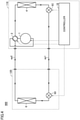
- Fig. 2 shows the functional configuration of air conditioner 100 in Fig. 1 , together with flow of refrigerant during a heating operation.
- refrigerant circulates in a circulation direction (second circulation direction) in order of compressor 1, four-way valve 2, heat exchanger 8, expansion valve 5B, internal heat exchanger 7, internal heat exchanger 6, expansion valve 5A, heat exchanger 4, and four-way valve 2.
- Refrigerant flowing out of outdoor unit 110 flows into indoor unit 120 through extension pipe ep2.
- Refrigerant flowing out of indoor unit 120 flows into outdoor unit 110 through extension pipe ep1.
- heat exchanger 8 serves as a condenser
- heat exchanger 4 serves as an evaporator.
- the input port of check valve 31 communicates with a suction port of compressor 1 through four-way valve 2.
- Refrigerant from four-way valve 2 flows through check valve 91 toward heat exchanger 8 without flowing through internal heat exchanger 7.
- switch 9 directs refrigerant from compressor 1 to flow to heat exchanger 8 without flowing through internal heat exchanger 7.
- the pressure of refrigerant flowing out of check valve 91 is lower than the pressure of refrigerant flowing into check valve 91 because of a pressure loss due to check valve 91. Most of the refrigerant from check valve 91 therefore flows toward heat exchanger 8.
- Refrigerant from heat exchanger 4 flows through internal heat exchanger 6 and check valve 32 in this order toward four-way valve 2, without flowing through check valve 31.
- switch 3 directs refrigerant from heat exchanger 4 to flow through internal heat exchanger 6 to compressor 1.
- internal heat exchanger 6 heat is exchanged between refrigerant from internal heat exchanger 7 and refrigerant from heat exchanger 4.
- the pressure of refrigerant flowing out of check valve 32 is lower than the pressure of refrigerant flowing into internal heat exchanger 6 because of a pressure loss due to internal heat exchanger 6 and check valve 32. Most of refrigerant from check valve 32 therefore flows toward four-way valve 2.
- node N1 is a node through which refrigerant flowing from four-way valve 2 to compressor 1 passes.
- Node N12 is a node through which refrigerant flowing from four-way valve 2 to extension pipe ep2 passes.
- Node N11 is a node through which refrigerant flowing from extension pipe ep2 to check valve 91 passes.
- Node N10 is a node through which refrigerant flowing from check valve 91 to heat exchanger 8 passes.
- Node N9 is a node through which refrigerant flowing from heat exchanger 8 to expansion valve 5B passes.
- Node N8 is a node through which refrigerant flowing from expansion valve 5B to internal heat exchanger 7 passes.
- Node N7 is a node through which refrigerant flowing from internal heat exchanger 7 to extension pipe ep1 passes.
- Node N6 is a node through which refrigerant flowing from extension pipe ep1 to internal heat exchanger 6 passes.
- Node N5 is a node through which refrigerant flowing from internal heat exchanger 6 to expansion valve 5A passes.
- Node N4 is a node through which refrigerant flowing from expansion valve 5A to heat exchanger 4 passes.
- Node N3 is a node through which refrigerant flowing from heat exchanger 4 to internal heat exchanger 6 passes.
- Node N2 is a node through which refrigerant flowing from internal heat exchanger 6 to four-way valve 2 passes.
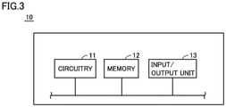
- Fig. 3 is a functional block diagram showing a configuration of controller 10 in Figs. 1 and 2 .
- controller 10 includes circuitry 11, a memory 12, and an input/output unit 13.
- Circuitry 11 may be dedicated hardware, or a CPU (Central Processing Unit) executing a program stored in memory 12.
- circuitry 11 is dedicated hardware, circuitry 11 is, for example, a single circuit, a composite circuit, a programmed processor, a parallel-programmed processor, an ASIC (Application Specific Integrated Circuit), an FGA (Field Programmable Gate Array), or a combination thereof.
- ASIC Application Specific Integrated Circuit
- FGA Field Programmable Gate Array
- Memory 12 includes a nonvolatile or volatile semiconductor memory (for example, RAM (Random Access Memory), ROM (Read Only Memory), flash memory, EPROM (Erasable Programmable Read Only Memory), or EEPROM (Electrically Erasable Programmable Read Only Memory)), a magnetic disc, a flexible disc, an optical disc, a compact disc, a mini disc, or a DVD (Digital Versatile Disc).
- the CPU is also called central processing unit, processing unit, arithmetic unit, microprocessor, microcomputer, processor, or DSP (Digital Signal Processor).
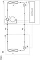
- Fig. 4 shows a functional configuration of an air conditioner 900 according to a comparative example, together with flow of refrigerant during a cooling operation.
- Fig. 5 shows the functional configuration of air conditioner 900 in Fig. 4 , together with flow of refrigerant during a heating operation.
- the configuration of air conditioner 900 corresponds to the configuration of air conditioner 100 shown in Figs. 1 and 2 , except that internal heat exchangers 6, 7 and switches 3, 9 of air conditioner 100 are not present and expansion valves 5A, 5B of air conditioner 100 are replaced with expansion valves 5C, 5D, respectively. Expansion valves 5C and 5D have respective structures similar to each other.
- the configuration of air conditioner 900 and the configuration of air conditioner 100 are similar to each other except for the above-identified features, and therefore, the description thereof is not herein repeated.
- the circulation direction of refrigerant in air conditioner 900 is switched between a direction for the cooling operation and a direction for the heating operation.
- liquid refrigerant flows into expansion valve 5C and wet steam flows into expansion valve 5D.
- liquid refrigerant flows into expansion valve 5D and wet steam flows into expansion valve 5C. It has to be assumed that both liquid refrigerant and wet steam may flow into each of expansion valves 5C, 5D in air conditioner 900.
- Fig. 6 shows an example of an internal structure of expansion valve 5 used in air conditioner 100 in Figs. 1 and 2 and air conditioner 900 in Figs. 4 and 5 .
- expansion valve 5 includes a main body 51, a valve body 52, a stepper motor 53, and coupling pipes 54, 55.
- valve chambers 511, 512 are formed, and these valve chambers communicate with each other through a valve seat 513 that is a hole through which refrigerant flows.
- Valve seat 513 is a cylindrical hole, for example.
- Coupling pipe 54 is connected to main body 51 so as to allow the outside and valve chamber 511 to communicate with each other.
- Coupling pipe 55 is connected to main body 51 so as to allow the outside and valve chamber 512 to communicate with each other.
- Valve body 52 is disposed to extend from stepper motor 53 toward valve seat 513 through valve chamber 511.
- Valve body 52 has a leading end 521 in an acute shape which is, for example, a conical shape.
- the diameter of valve body 52 is substantially identical to the diameter of valve seat 513.
- Valve body 52 is moved by stepper motor 53 in the directions indicated by an arrow M1 and its position is determined.
- the position of valve body 52 determines the ratio of leading end 521 occupying valve seat 513 to the whole valve seat 513.
- stepper motor 53 determines the opening degree of expansion valve 5 to regulate the flow rate through valve seat 513 per unit time and regulate the pressure reduction by expansion valve 5.
- an expansion valve for a refrigeration cycle apparatus is selected by determining the Cv value based on the specifications of a fluid for the refrigeration cycle apparatus and comparing the Cv value with Cv values presented by valve manufactures so as to determine the valve type and the diameter of the valve seat of the expansion valve. Comparison of the Cv values is one of convenient ways used for selecting an expansion valve.
- the Cv value is expressed by the following expression (1).
- ⁇ is a constant
- Gr is the refrigerant flow rate [kg/s]
- ⁇ P is the pressure difference [MPa] between refrigerant flowing into the expansion valve and the refrigerant flowing out of the expansion valve
- ⁇ is the density [kg/m 3 ] of the refrigerant flowing into the expansion valve.
- Fig. 7 is an enlarged view of leading end 521 and valve seat 513 and therearound of expansion valve 5 in Fig. 6 .
- Leading end 521 shown in Fig. 7 (b) has a diameter D2 larger than a diameter D1 of leading end 521 shown in Fig. 7 (a) .
- the larger the diameter of leading end 521, the larger the maximum value of the Cv value of expansion valve 5, and therefore, a maximum value Cv2 of the Cv value of expansion valve 5 shown in Fig. 7 (b) is larger than a maximum value Cv1 of the Cv value of expansion valve 5 shown in Fig. 7 (a) .
- Expansion valve 5 shown in Fig. 7 (a) and expansion valve 5 shown in Fig. 7 (b) have the same height HI of leading end 521 and also have the same minimum value Cv0 of the Cv value.
- Fig. 8 shows a relation between the opening degree and the Cv value of an expansion valve.
- a relation R1 represents a relation between the opening degree and the Cv value of expansion valve 5 in Fig. 7 (a) .
- a relation R2 represents a relation between the opening degree and the Cv value of expansion valve 5 in Fig. 7 (b) .
- the relation between the opening degree and the Cv value of an expansion valve is represented by a monotonous increase, for example, and Fig. 8 shows a case where each of Relations R1 and R2 is a linear relation.
- An opening degree Omin is the minimum opening degree of expansion valve 5
- an opening degree Omax is the maximum opening degree of expansion valve 5.
- An opening degree difference Od is an opening degree difference corresponding to the minimum operational amount of the stepper motor of expansion valve 5.
- a resolution Rs2 of the Cv value of expansion valve 5 in Fig. 7 (b) is larger than a resolution Rs1 of the Cv value of expansion valve 5 in Fig. 7 (a) .
- the refrigerant that flows into the expansion valve may both be liquid refrigerant and wet steam
- the difference between the maximum value and the minimum value of the Cv value is large, and therefore, the resolution of the Cv value of the expansion valve is large.
- the controllability for the expansion valve is deteriorated to increase the difference between the actual refrigerant flow rate and a desired refrigerant flow rate. Since the refrigerant flow rate can be regulated to regulate the capacity of the refrigeration cycle apparatus, deterioration of the controllability for the expansion valve results in deterioration of the controllability for the refrigeration cycle apparatus.
- refrigerant in air conditioner 100 that flows into expansion valve 5A and that flows into expansion valve 5B are cooled by internal heat exchangers 6 and 7, respectively.
- the density of refrigerant flowing into expansion valves 5A, 5B can be made higher than the density of refrigerant flowing into expansion valves 5C, 5D in air conditioner 900, and therefore, the resolution of expansion valves 5A, 5B can be made lower than the resolution of expansion valves 5C, 5D. Since the controllability for expansion valves 5A, 5B is improved relative to the controllability for expansion valves 5C, 5D, the controllability for air conditioner 100 can be improved relative to the controllability for air conditioner 900.
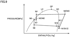
- Fig. 9 is a P-h diagram showing change of the state of refrigerant circulating through air conditioner 100 in Fig. 1 .
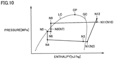
- Fig. 10 is a P-h diagram showing change of the state of refrigerant circulating through air conditioner 100 in Fig. 2 .
- Respective states shown in Figs. 9 and 10 correspond respectively to the states of refrigerant at nodes N1 to N12 in Figs. 1 and 2 .
- Curves LC and GC represent a saturated liquid line and a saturated vapor line, respectively. Saturated liquid line LC and saturated vapor line GC connect to each other at a critical point CP.
- Refrigerant in the state on saturated liquid line LC and refrigerant in the state with an enthalpy lower than the enthalpy of the state on saturated liquid line LC are liquid refrigerant.
- the region of liquid refrigerant includes saturated liquid line LC.
- Refrigerant in the state included in the region between saturated liquid line LC and saturated vapor line GC is wet steam.
- Refrigerant in the state on saturated vapor line GC and refrigerant in the state with an enthalpy higher than the enthalpy of the state on saturated vapor line GC are gaseous liquid (gas liquid).
- the region of gas refrigerant includes saturated vapor line GC.
- the process from the state at node N1 to the state at node N2 is an adiabatic compression process through compressor 1. Because there is almost no state change of the refrigerant flowing from compressor 1 to heat exchanger 4, the state at node N3 is almost the same as the state at node N2.
- the process from the state at node N3 to the state at node N4 is a condensation process through heat exchanger 4 serving as a condenser.
- the state at node N4 is included in the region of liquid refrigerant. Liquid refrigerant at node N4 flows into expansion valve 5A.
- the process from the state at node N4 to the state at node N5 is an adiabatic expansion process through expansion valve 5A.
- the state at node N5 is included in the region of wet steam.
- refrigerant from compressor 1 flows toward heat exchanger 4 without passing through internal heat exchanger 6.
- internal heat exchanger 6 there is almost no heat exchange between refrigerants, and therefore, the state at node N6 is almost the same as the state at node N5.
- a pressure loss is generated due to extension pipe ep1.
- the state at node N7 is also included in the region of wet steam, like the state at node N6. Namely, wet steam flows through extension pipe ep1 during the cooling operation.
- the process from the state at node N7 to the state at node N8 is a cooling process through internal heat exchanger 7.
- the state at node N8 is a state shifted from the state at node N7 in the direction in which the enthalpy decreases, and included in the region of liquid refrigerant. Liquid refrigerant in the state at node N8 flows into expansion valve 5B.
- the process from the state at node N8 to the state at node N9 is an adiabatic expansion process through expansion valve 5B.
- the process from the state at node N9 to the state at node N10 is an evaporation process through heat exchanger 8 serving as an evaporator.
- the process from the state at node N10 to the state at node N11 is a heating process through internal heat exchanger 7.
- a pressure loss is generated due to extension pipe ep2. Because there is almost no state change of the refrigerant flowing from node N12 toward node N1 through four-way valve 2, the state at node N1 is almost the same as the state at node N12.
- the process from the state at node N1 to the state at node N12 is an adiabatic compression process through compressor 1.
- a pressure loss is generated due to extension pipe ep2.
- the state at node N10 is almost the same as the state at node N11.
- the process from the state at node N10 to the state at node N9 is a condensation process through heat exchanger 8 serving as a condenser.
- the state at node N9 is included in the region of liquid refrigerant.
- Liquid refrigerant in the state at node N9 flows into expansion valve 5B.
- the process from the state at node N9 to the state at node N8 is an adiabatic expansion process through expansion valve 5B.
- the state at node N8 is included in the region of wet steam.
- refrigerant from compressor 1 flows toward heat exchanger 8 without passing through internal heat exchanger 7.
- internal heat exchanger 7 there is almost no heat exchange between refrigerants, and therefore, the state at node N7 is almost the same as the state at node N8.
- a pressure loss is generated due to extension pipe ep1.
- the state at node N6 is also included in the region of wet steam, like the state at node N7. Namely, wet steam also flows through extension pipe ep1 during the heating operation.
- the process from the state at node N6 to the state at node N5 is a cooling process through internal heat exchanger 6.
- the state at node N5 is a state shifted from the state at node N6 in the direction in which the enthalpy decreases, and included in the region of liquid refrigerant. Liquid refrigerant in the state at node N5 flows into expansion valve 5A.
- the process from the state at node N5 to the state at node N4 is an adiabatic expansion process through expansion valve 5A.
- the process from the state at node N4 to the state at node N3 is an evaporation process through heat exchanger 4 serving as an evaporator.
- the process from the state at node N3 to the state at node N2 is a heating process through internal heat exchanger 6. Because there is almost no state change of the refrigerant flowing from node N2 toward node N1 through four-way valve 2, the state at node N1 is almost the same as the state at node N2.
- the refrigeration cycle apparatus can suppress deterioration of the controllability.
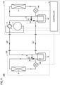
- FIG. 11 shows a functional configuration of an air conditioner 200 that is an example of a refrigeration cycle apparatus according to Embodiment 2, together with flow of refrigerant during a cooling operation.
- the configuration of air conditioner 200 corresponds to the configuration in Fig. 1 , except that internal heat exchangers 6 and 7 in Fig. 1 are replaced respectively with a receiver 62 (first receiver) and a receiver 72 (second receiver) that are capable of storing liquid refrigerant.
- the configuration of air conditioner 200 and that in Fig. 1 are similar to each other except for the above-identified features, and therefore, the description thereof is not herein repeated.
- wet steam from expansion valve 5A flows into receiver 62.
- the liquid refrigerant may flow out of receiver 62.
- the density of liquid refrigerant is higher than the density of wet steam, the amount of the liquid refrigerant stored in receiver 62 decreases with time, and consequently, the refrigerant flowing out of receiver 62 changes form the liquid refrigerant to the wet steam.
- the liquid refrigerant flows temporarily through extension pipe ep1 and, after the refrigerant flowing out of receiver 62 changes from the liquid refrigerant to the wet steam, the wet steam flows through extension pipe ep1.
- the refrigerant flowing from extension pipe ep1 into receiver 72 is cooled by refrigerant from heat exchanger 8 serving as an evaporator. As a result, liquid refrigerant flows out of receiver 72 toward expansion valve 5B while excess refrigerant is stored in receiver 72.
- Fig. 12 shows the functional configuration of air conditioner 200 in Fig. 11 , together with flow of refrigerant during a heating operation.
- wet steam from expansion valve 5B flows into receiver 72.
- the liquid refrigerant may flow out of receiver 72.
- the amount of the liquid refrigerant stored in receiver 72 decreases with time, and consequently, the refrigerant flowing out of receiver 72 changes form the liquid refrigerant to the wet steam.
- the liquid refrigerant flows temporarily through extension pipe ep1 and, after the refrigerant flowing out of receiver 72 changes from the liquid refrigerant to the wet steam, the wet steam flows through extension pipe ep1.
- the refrigerant flowing from extension pipe ep1 into receiver 62 is cooled by refrigerant from heat exchanger 4 serving as an evaporator. As a result, liquid refrigerant flows out of receiver 62 toward expansion valve 5A while excess refrigerant is stored in receiver 62.
- the above-described refrigeration cycle apparatus includes one outdoor unit and one indoor unit.
- the refrigeration cycle apparatus according to the embodiments may include a plurality of indoor units and/or a plurality of outdoor units.
- each of switches 3 and 9 in Figs. 1 , 2 , 11 , and 12 is implemented by two check valves.
- the configuration of the switch of the refrigeration cycle apparatus according to the embodiments is not limited to the configuration including the two check valves.
- an on-off valve controlled by the controller may be used.
- the function of the switch may also be implemented by a three-way valve.
- Fig. 13 shows a functional configuration of an air conditioner 200A that is an example of a refrigeration cycle apparatus according to a modification of Embodiment 2, together with flow of refrigerant during a cooling operation.
- the configuration of air conditioner 200A corresponds to that in Fig. 11 except that switches 3 and 9 in Fig. 11 are replaced respectively with a three-way valve 3A (first switch) and a three-way valve 9A (second switch) and that controller 10 is replaced with a controller 10A.
- the configuration in Fig. 13 is similar to that in Fig. 11 except for the above-identified features, and therefore, the description thereof is not herein repeated.
- three-way valve 3A has a port P31 (first port), a port P32 (second port), and a port P33 (third port). Three-way valve 3A selectively switches the port that communicates with port P31 between ports P32 and P33. Receiver 62 is connected between ports P32 and P33. Port P31 is connected to heat exchanger 4.
- Three-way valve 9A has a port P91 (fourth port), a port P92 (fifth port), and a port P93 (sixth port). Three-way valve 9A selectively switches the port that communicates with port P91 between ports P92 and P93. Receiver 72 is connected between ports P92 and P93. Port P91 is connected to heat exchanger 8.
- port P32 communicates with the discharge port of compressor 1 through four-way valve 2.
- Controller 10A causes port P31 to communicate with port P32 and causes port P91 to communicate with port P92.
- Controller 10A controls three-way valve 3A to direct refrigerant from compressor 1 to flow to heat exchanger 4 without flowing through receiver 62.
- Controller 10A controls three-way valve 9A to direct refrigerant from heat exchanger 8 to flow through receiver 72 to compressor 1.
- Fig. 14 shows the functional configuration of air conditioner 200A in Fig. 13 , together with flow of refrigerant during a heating operation.
- port P32 communicates with the suction port of compressor 1 through four-way valve 2.
- Controller 10A causes port P31 to communicate with port P33 and causes port P91 to communicate with port P93.
- Controller 10A controls three-way valve 9A to direct refrigerant from compressor 1 to flow to heat exchanger 8 without flowing through receiver 72.
- Controller 10A controls three-way valve 3A to direct refrigerant from heat exchanger 4 to flow through receiver 62 to compressor 1.
- the refrigeration cycle apparatuses according to Embodiment 2 and the modification can suppress deterioration of the controllability.
Landscapes
- Engineering & Computer Science (AREA)
- Physics & Mathematics (AREA)
- Mechanical Engineering (AREA)
- Thermal Sciences (AREA)
- General Engineering & Computer Science (AREA)
- Compression-Type Refrigeration Machines With Reversible Cycles (AREA)
- Air Conditioning Control Device (AREA)
Applications Claiming Priority (1)
| Application Number | Priority Date | Filing Date | Title |
|---|---|---|---|
| PCT/JP2019/015142 WO2020202553A1 (ja) | 2019-04-05 | 2019-04-05 | 冷凍サイクル装置 |
Publications (2)
| Publication Number | Publication Date |
|---|---|
| EP3951284A1 true EP3951284A1 (de) | 2022-02-09 |
| EP3951284A4 EP3951284A4 (de) | 2022-04-06 |
Family
ID=72667324
Family Applications (1)
| Application Number | Title | Priority Date | Filing Date |
|---|---|---|---|
| EP19923242.2A Withdrawn EP3951284A4 (de) | 2019-04-05 | 2019-04-05 | Kältekreislaufvorrichtung |
Country Status (5)
| Country | Link |
|---|---|
| US (1) | US20220136741A1 (de) |
| EP (1) | EP3951284A4 (de) |
| JP (1) | JP7524161B2 (de) |
| CN (1) | CN113646593B (de) |
| WO (1) | WO2020202553A1 (de) |
Families Citing this family (3)
| Publication number | Priority date | Publication date | Assignee | Title |
|---|---|---|---|---|
| JP7422935B2 (ja) * | 2021-03-03 | 2024-01-26 | 三菱電機株式会社 | 冷凍サイクル装置 |
| WO2024079852A1 (ja) * | 2022-10-13 | 2024-04-18 | 三菱電機株式会社 | 冷凍サイクル装置 |
| EP4397923A1 (de) | 2023-01-09 | 2024-07-10 | Viessmann Climate Solutions SE | Wärmepumpe und verfahren zum betreiben einer wärmepumpe |
Family Cites Families (18)
| Publication number | Priority date | Publication date | Assignee | Title |
|---|---|---|---|---|
| JPS6058145B2 (ja) | 1982-12-03 | 1985-12-18 | 株式会社東芝 | カ−ド集積装置 |
| JPH03271659A (ja) * | 1990-03-19 | 1991-12-03 | Matsushita Refrig Co Ltd | 多室型空気調和機 |
| JP3242217B2 (ja) * | 1993-07-09 | 2001-12-25 | 東芝キヤリア株式会社 | 空気調和機 |
| JPH09152195A (ja) * | 1995-11-28 | 1997-06-10 | Sanyo Electric Co Ltd | 冷凍装置 |
| JPH10332212A (ja) * | 1997-06-02 | 1998-12-15 | Toshiba Corp | 空気調和装置の冷凍サイクル |
| CN1171050C (zh) * | 1999-09-24 | 2004-10-13 | 三洋电机株式会社 | 多级压缩制冷装置 |
| JP2001235239A (ja) * | 2000-02-23 | 2001-08-31 | Seiko Seiki Co Ltd | 超臨界蒸気圧縮サイクル装置 |
| JP4407012B2 (ja) | 2000-06-06 | 2010-02-03 | ダイキン工業株式会社 | 冷凍装置 |
| JP4459776B2 (ja) * | 2004-10-18 | 2010-04-28 | 三菱電機株式会社 | ヒートポンプ装置及びヒートポンプ装置の室外機 |
| JP3982545B2 (ja) * | 2005-09-22 | 2007-09-26 | ダイキン工業株式会社 | 空気調和装置 |
| JP4884365B2 (ja) * | 2007-12-28 | 2012-02-29 | 三菱電機株式会社 | 冷凍空調装置、冷凍空調装置の室外機および冷凍空調装置の制御装置 |
| JP2009180406A (ja) * | 2008-01-30 | 2009-08-13 | Calsonic Kansei Corp | 超臨界冷凍サイクル |
| JP5627417B2 (ja) * | 2010-11-26 | 2014-11-19 | 三菱電機株式会社 | 二元冷凍装置 |
| WO2013160929A1 (ja) * | 2012-04-23 | 2013-10-31 | 三菱電機株式会社 | 冷凍サイクルシステム |
| EP3040642B1 (de) * | 2013-08-28 | 2021-06-02 | Mitsubishi Electric Corporation | Klimaanlage |
| GB2533042B (en) * | 2013-08-30 | 2020-08-12 | Mitsubishi Electric Corp | Air-conditioning apparatus |
| JP6379769B2 (ja) * | 2014-07-14 | 2018-08-29 | 株式会社富士通ゼネラル | 空気調和装置 |
| CN108332285B (zh) * | 2017-12-29 | 2019-12-06 | 青岛海尔空调器有限总公司 | 空调器系统 |
-
2019
- 2019-04-05 JP JP2021511055A patent/JP7524161B2/ja active Active
- 2019-04-05 WO PCT/JP2019/015142 patent/WO2020202553A1/ja not_active Ceased
- 2019-04-05 EP EP19923242.2A patent/EP3951284A4/de not_active Withdrawn
- 2019-04-05 US US17/432,543 patent/US20220136741A1/en not_active Abandoned
- 2019-04-05 CN CN201980094987.9A patent/CN113646593B/zh not_active Expired - Fee Related
Also Published As
| Publication number | Publication date |
|---|---|
| EP3951284A4 (de) | 2022-04-06 |
| JP7524161B2 (ja) | 2024-07-29 |
| CN113646593A (zh) | 2021-11-12 |
| JPWO2020202553A1 (de) | 2020-10-08 |
| CN113646593B (zh) | 2022-11-15 |
| WO2020202553A1 (ja) | 2020-10-08 |
| US20220136741A1 (en) | 2022-05-05 |
Similar Documents
| Publication | Publication Date | Title |
|---|---|---|
| JP5318099B2 (ja) | 冷凍サイクル装置、並びにその制御方法 | |
| JP6594599B1 (ja) | 空気調和装置 | |
| EP3006866A1 (de) | Klimaanlage | |
| EP2420765B1 (de) | Wärmequelleneinheit | |
| EP0586193A1 (de) | Kältekreislauf | |
| CN113167517A (zh) | 空调装置 | |
| JPH0232547B2 (de) | ||
| CN105485805A (zh) | 空气调节机 | |
| CN114127479B (zh) | 制冷装置 | |
| US11112140B2 (en) | Air conditioning apparatus | |
| EP3951284A1 (de) | Kältekreislaufvorrichtung | |
| KR101901540B1 (ko) | 공기 조화 장치 | |
| JP6021955B2 (ja) | 冷凍サイクル装置、及び、冷凍サイクル装置の制御方法 | |
| JPWO2018096580A1 (ja) | 冷凍サイクル装置 | |
| JP7716599B2 (ja) | 冷凍サイクル装置および空気調和装置 | |
| CN109312961B (zh) | 制冷装置的热源机组 | |
| JP2001349623A (ja) | 冷凍装置 | |
| US20100131115A1 (en) | Controlling method of air conditioner | |
| GB2585594A (en) | Refrigerating apparatus | |
| JPWO2017094172A1 (ja) | 空気調和装置 | |
| US20210302072A1 (en) | Air conditioner | |
| JP2018146169A (ja) | 空調機 | |
| JP7796887B2 (ja) | 冷凍サイクル装置および空気調和装置 | |
| US11629894B2 (en) | Economizer control systems and methods | |
| US20240151442A1 (en) | Refrigeration cycle apparatus |
Legal Events
| Date | Code | Title | Description |
|---|---|---|---|
| STAA | Information on the status of an ep patent application or granted ep patent |
Free format text: STATUS: THE INTERNATIONAL PUBLICATION HAS BEEN MADE |
|
| PUAI | Public reference made under article 153(3) epc to a published international application that has entered the european phase |
Free format text: ORIGINAL CODE: 0009012 |
|
| STAA | Information on the status of an ep patent application or granted ep patent |
Free format text: STATUS: REQUEST FOR EXAMINATION WAS MADE |
|
| 17P | Request for examination filed |
Effective date: 20210928 |
|
| AK | Designated contracting states |
Kind code of ref document: A1 Designated state(s): AL AT BE BG CH CY CZ DE DK EE ES FI FR GB GR HR HU IE IS IT LI LT LU LV MC MK MT NL NO PL PT RO RS SE SI SK SM TR |
|
| A4 | Supplementary search report drawn up and despatched |
Effective date: 20220307 |
|
| RIC1 | Information provided on ipc code assigned before grant |
Ipc: F25B 41/30 20210101ALI20220301BHEP Ipc: F25B 41/20 20210101ALI20220301BHEP Ipc: F25B 49/02 20060101ALI20220301BHEP Ipc: F25B 13/00 20060101ALI20220301BHEP Ipc: F25B 1/00 20060101AFI20220301BHEP |
|
| DAV | Request for validation of the european patent (deleted) | ||
| DAX | Request for extension of the european patent (deleted) | ||
| GRAP | Despatch of communication of intention to grant a patent |
Free format text: ORIGINAL CODE: EPIDOSNIGR1 |
|
| STAA | Information on the status of an ep patent application or granted ep patent |
Free format text: STATUS: GRANT OF PATENT IS INTENDED |
|
| INTG | Intention to grant announced |
Effective date: 20240620 |
|
| STAA | Information on the status of an ep patent application or granted ep patent |
Free format text: STATUS: THE APPLICATION IS DEEMED TO BE WITHDRAWN |
|
| 18D | Application deemed to be withdrawn |
Effective date: 20241022 |