EP3950461B1 - Kopplerstruktur für transkontinentale eisenbahnwagen - Google Patents
Kopplerstruktur für transkontinentale eisenbahnwagen Download PDFInfo
- Publication number
- EP3950461B1 EP3950461B1 EP19920871.1A EP19920871A EP3950461B1 EP 3950461 B1 EP3950461 B1 EP 3950461B1 EP 19920871 A EP19920871 A EP 19920871A EP 3950461 B1 EP3950461 B1 EP 3950461B1
- Authority
- EP
- European Patent Office
- Prior art keywords
- coupler
- head unit
- head
- connector part
- coupler structure
- Prior art date
- Legal status (The legal status is an assumption and is not a legal conclusion. Google has not performed a legal analysis and makes no representation as to the accuracy of the status listed.)
- Active
Links
Images


Classifications
-
- H—ELECTRICITY
- H05—ELECTRIC TECHNIQUES NOT OTHERWISE PROVIDED FOR
- H05B—ELECTRIC HEATING; ELECTRIC LIGHT SOURCES NOT OTHERWISE PROVIDED FOR; CIRCUIT ARRANGEMENTS FOR ELECTRIC LIGHT SOURCES, IN GENERAL
- H05B3/00—Ohmic-resistance heating
- H05B3/10—Heating elements characterised by the composition or nature of the materials or by the arrangement of the conductor
- H05B3/16—Heating elements characterised by the composition or nature of the materials or by the arrangement of the conductor the conductor being mounted on an insulating base
-
- B—PERFORMING OPERATIONS; TRANSPORTING
- B61—RAILWAYS
- B61G—COUPLINGS; DRAUGHT AND BUFFING APPLIANCES
- B61G5/00—Couplings for special purposes not otherwise provided for
- B61G5/04—Couplings for special purposes not otherwise provided for for matching couplings of different types, i.e. transitional couplings
-
- H—ELECTRICITY
- H05—ELECTRIC TECHNIQUES NOT OTHERWISE PROVIDED FOR
- H05B—ELECTRIC HEATING; ELECTRIC LIGHT SOURCES NOT OTHERWISE PROVIDED FOR; CIRCUIT ARRANGEMENTS FOR ELECTRIC LIGHT SOURCES, IN GENERAL
- H05B2203/00—Aspects relating to Ohmic resistive heating covered by group H05B3/00
- H05B2203/014—Heaters using resistive wires or cables not provided for in H05B3/54
Definitions
- the coupler prevents accidents caused by contact between a leading car and a rear car by always maintaining a predetermined distance therebetween.
- the coupler serves as a medium to transmit power from an engine room to each car, and a knuckle type automatic coupler or a lock type close coupler is mainly used as the coupler.
- Transcontinental railroads refer to a railroad route that is being promoted with a goal of connecting Korea to China, Central Asia, Russia, and Europe.
- a connecting shaft 9 is inserted through the coupler body 1 and the shaft hole 2, 2' of the shank 7, and one of the securing pin holes 6 and the securing hole 8 of the shank 7 match with each other while being adjusted by the stopper 5, 5', the holes being formed around the shaft hole 2 of a coupler body 1.
- a securing pin 10 is inserted into the securing pin hole and the securing hole 8 to selectively use a coupler matching with a coupler provided in a car to be connected.
- the coupler body 1 has two different head forms integrated into a single body so that it is possible to connect car frames having different type couplers to each other without replacement of a coupler.
- the coupler body 1 having the two different head forms is supported to the shank 7 only by a hinge coupling part, so support strength of the coupler may be week.
- a head not in use i.e. a head not coupled to the car body
- the load on the coupler body 1 during traveling is eccentrically operated. Therefore, the traveling stability of the railroad car is degraded, and the load on a coupling portion between the shank 7 and the coupler body 1 causes deformation or breakage of the coupler.
- Another objective of the present disclosure is intended to provide a coupler structure for transcontinental railroad cars, the coupler structure being configured to distribute the load on the coupler during traveling of a transcontinental railroad car to prevent the traveling stability of the transcontinental railroad car from being degraded due to the eccentric load.
- a coupler structure for transcontinental railroad cars is configured as follows.
- the coupler structure for transcontinental railroad cars includes a head unit having two different coupler forms integrated into a single body; and a shank unit connected to a railroad car body while being coupled to the head unit, wherein the shank unit may include a U-shaped head connector part and a securing part, the head unit being inserted into and hinged to the U-shaped head connector part, and the securing part extending from a rear end of the head connector part and fixedly mounted on the car body, supporting parts may be projected from upper and lower surfaces of a rear end of the head unit, and supporting grooves into which the supporting parts may be inserted may be formed on an inner surface of the head connector part.
- the shank unit may include a U-shaped head connector part and a securing part, the head unit being inserted into and hinged to the U-shaped head connector part, and the securing part extending from a rear end of the head connector part and fixedly mounted on the car body, supporting parts may be projected from upper and lower surfaces of a rear end of the head unit
- the supporting parts and the supporting grooves may be formed in arc forms.
- First and second hinge holes into which a hinge pin may be inserted and coupled, may be respectively formed in a location of the head unit and a location of the head connector part that correspond to each other, and an insertion hole and a coupling hole, into which a securing pin for securing the head unit to the head connector part may be inserted and coupled, may be respectively formed on rear portions of the first and second hinge holes.
- the insertion hole may include first to third insertion holes that may be spaced apart from each other at predetermined intervals
- the coupling hole may include first and second coupling holes that may be spaced apart from each other at a predetermined interval
- the securing pin may include first and second securing pins that may be respectively coupled to the first and second coupling holes and the first and second insertion holes or to the first and second coupling holes and the second and third insertion holes.
- a supporting frame may be coupled to a location outside the head connector part, the supporting frame having an accommodating space for accommodating the head unit therein.
- First and second connector parts may be respectively projected on opposite portions of the head unit, the first and second connector parts being configured to be fastened and secured to the head connector part by a fastening means while being accommodated in the accommodating space of the supporting frame.
- a heating wire may be inserted and provided in the supporting frame.
- the coupling structure can support the head unit having the two different coupler forms integrated into a single body more stably, distribute eccentric load, bending load, torsional load, etc. on the coupler, and improve the load support strength of the coupler. Therefore, the traveling stability of a transcontinental railroad car can be improved and the durability of the coupler can be dramatically improved.
- FIG. 2 is a perspective view showing a coupler structure for transcontinental railroad cars according to a first embodiment of the present disclosure.
- FIG. 3 is an exploded-perspective view showing the coupler structure for transcontinental railroad cars shown in FIG. 2 .
- FIG. 4 is an axial-sectional view showing the coupler structure for transcontinental railroad cars shown in FIG. 2 .
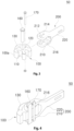
- FIG. 5 is an exploded-perspective view showing a coupler structure for transcontinental railroad cars according to a second embodiment of the present disclosure.
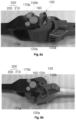
- FIGS. 6A and 6B are views showing the coupler structure of the present disclosure shown in FIG. 5 to which another coupler having a different shape is coupled.
- FIG. 7 is a view showing results of structural analysis of the coupler structure of the present disclosure shown in FIG. 5 .
- FIG. 8 is a perspective view showing a coupler structure for transcontinental railroad cars according to a third embodiment of the present disclosure.
- FIG. 9 is a plan view showing the coupler structure of the present disclosure shown in
- the present disclosure relates to a coupler structure for transcontinental railroad cars, the coupled structure increasing support strength of a duplex coupler provided in transcontinental railroad cars and improving durability by distributing the load on the coupler.
- the coupler structure includes a head unit 100 and a shank unit 200, as shown in FIGS. 2 and 3 .
- the head unit 100 serves to connect a car body to another car body, the car bodies being adjacent to each other.
- the head unit 100 has a structure in which two different coupler forms are integrated into a single body.
- the coupler forms included in the head unit 100 may include two forms among widely used various coupler forms.
- the coupler structure of the present disclosure is used for transcontinental railroad cars, so the form of the head unit 100 may be the structure consisting of an AAR (Association of American Railroads) type coupler (a first coupler 100a) used in most countries including Korea and a CA-3 type coupler (a second coupler 100b) mainly used in Russia and China are integrated into a single body, as shown in FIG. 3 .
- AAR Association of American Railroads
- a first coupler 100a used in most countries including Korea
- CA-3 type coupler a second coupler 100b
- the present disclosure will be described with reference to the above structure.
- the shank unit 200 is connected to a rear portion of the head unit 100 and serves to allow the coupler 50 to be fixedly mounted to the car body of a transcontinental railroad car.
- the shank unit 200 includes a head connector part 210 and a securing part 220.
- the head unit 100 is hinged to the head connector part 210, and the securing part 220 is fixedly mounted to the car body.
- the head connector part 210 is formed in a 'U'-shape having an open front portion so that the head unit 100 may be inserted into and coupled to the inside of the head connector part 210 through the open portion.
- the securing part 220 is formed in a shank shape that extends rearward of the head connector part 210. A rear end of the securing part 220 is coupled to the car body, whereby the coupler 50 may be fixedly mounted to the car body.
- a first hinge hole 110 is vertically formed in a center portion of the head unit 100, and a second hinge hole 212 is formed in a portion of the head connector part 210 that corresponds to the location of the first hinge hole 110.
- the above-described structure may be configured such that, the head unit 100 may be hinged to the inside of the head connector part 210 by a hinge pin 160.
- the head unit 100 is hinged to the inside of the head connector part 210 by the hinge pin 160 that is inserted into and coupled to the second hinge hole 212 formed in the head connector part 210 and the first hinge hole 110 formed in the head unit 100. Therefore, even when the coupler 50 needs to be replaced, the hinge pin 160 serves as a shaft, without separating the head unit 100 from the head connector part 210, the first coupler 100a and the second coupler 100b may be replaced by rotation on the hinge pin 160.
- an insertion hole 120 is formed at rear of the first hinge hole 110 formed in the head unit 100, and a coupling hole 214 is formed on a location, which corresponds to the location of the insertion hole 120, in rear of the second hinge hole 212 formed in the head connector part 210.
- the insertion hole 120 and the coupling hole 214 serve to receive and to be coupled to a securing pin 170 provided for fixing the head unit 100.
- the securing pin 170 serves to solidly fix the head unit 100 to the head connector part 210 of the shank unit 200 and to support the load applied to the coupler 50 during traveling of a transcontinental railroad car. While the head unit 100 is coupled to the head connector part 210 by the hinge pin 160, the securing pin 170 is inserted into and coupled to the head unit 100 and the head connector part 210 through the insertion hole 120 and the coupling hole 214 respectively formed in the head unit 100 and the head connector part 210. Accordingly, the head unit 100 may be solidly fixed to the head connector part 210.
- supporting parts 130 are respectively formed while being projected on upper and lower surfaces of a rear end of the head unit 100, and supporting grooves 216 into which the supporting parts 130 are inserted are formed on an inner surface of the head connector part 210.
- the supporting parts 130 and the supporting grooves 216 serve to improve support strength of the head unit 100 coupled to the head connector part 210.
- the load on the coupler 50 is supported only by the hinge pin 160 and the securing pin 170, so that load support strength is reduced with respect to the load transmitted from various directions, such as eccentric load, bending load, torsional load, etc.
- the supporting parts 130 that are respectively projected on upper and lower portions of the head unit 100 are inserted into and coupled to the supporting grooves 216 formed on the head connector part 210. Therefore, a supporting area with respect to the head unit 100 increases so as to dramatically improve the support strength with respect to the lead on the head unit 100.
- the coupler structure for transcontinental railroad cars is configured as follows.
- the insertion hole 120 formed in the head unit 100 includes first to third insertion holes 120a, 120b, and 120c that are disposed to be spaced apart from each other at predetermined intervals.
- the coupling hole 214 formed in the head connector part 210 also includes first to second coupling holes 214a and 214b that are disposed to be spaced apart from each other at a predetermined interval.
- the first to third insertion holes and the first and second coupling holes serve to allow the securing pin 170, which is located in rear of the hinge pin 160 and fix the head unit 100 to the head connector part 210, to be inserted into and coupled to two locations.
- the head unit 100 is fixed by first and second securing pins 170a and 170b that is inserted to be spaced apart from each other at rear of a hinge coupling portion between the head unit 100 and the head connector part 210, whereby the head unit 100 may be solidly fixed to the head connector part 210 and the load support strength of the coupler may be improved.
Landscapes
- Engineering & Computer Science (AREA)
- Mechanical Engineering (AREA)
- Train Traffic Observation, Control, And Security (AREA)
- Connection Of Plates (AREA)
Claims (7)
- Kupplungsstruktur (50) für transkontinentale Eisenbahnwagen, wobei die Kupplungsstruktur aufweist:eine Kopfeinheit (100), die zwei unterschiedliche Kupplungsformen hat, die in einen einzigen Körper integriert sind, undeine Schafteinheit (200), die mit einem Eisenbahnwagenkörper verbindbar ist, während sie mit der Kopfeinheit gekuppelt ist,wobei die Schafteinheit (200) einen U-förmigen Kopfverbinderabschnitt (210) und einen Sicherungsabschnitt (220) aufweist, wobei die Kopfeinheit (100) in den U-förmigen Kopfverbinderabschnitt (210) eingesetzt und damit gelenkig verbunden ist, und wobei sich der Sicherungsabschnitt (220) von einem hinteren Ende des Kopfverbinderabschnitts (210) aus erstreckt und an dem Wagenkörper fest anbringbar ist,dadurch gekennzeichnet, dass Halteabschnitte (130) von der oberen und der unteren Fläche eines hinteren Endes der Kopfeinheit (100) aus vorstehen, undHaltenuten (216), in welche die Halteabschnitte (130) eingesetzt sind, an einer inneren Fläche des Kopfverbinderabschnitts (210) ausgebildet sind.
- Kupplungsstruktur (50) gemäß Anspruch 1, wobei die Halteabschnitte (130) und die Haltenuten (216) in Bogenformen ausgebildet sind.
- Kupplungsstruktur (50) gemäß Anspruch 1, wobei ein erstes und ein zweites Gelenkloch (110, 212), in welche ein Gelenkstift (160) eingesetzt und damit gekuppelt ist, jeweils zugeordnet in einer Position der Kopfeinheit (100) und einer Position des Kopfverbinderabschnitts (210), die zueinander korrespondieren, ausgebildet sind, und ein Einsetzloch (120) und ein Kupplungsloch (214), in welche ein Sicherungsstift (170) zum Sichern der Kopfeinheit (100) an dem Kopfverbinderabschnitt (210) eingesetzt und damit gekuppelt ist, jeweils zugeordnet an hinteren Abschnitten von der Kopfeinheit (100) und von dem Kopfverbindungsabschnitt (210) bezüglich des ersten und des zweiten Gelenklochs (110, 212) ausgebildet sind.
- Kupplungsstruktur (50) gemäß Anspruch 3, wobei das Einsetzloch (120) ein erstes bis drittes Einsetzloch (120a, 120b, 120c) aufweist, die in vorbestimmten Abständen im Abstand voneinander sind, wobei das Kupplungsloch (214) ein erstes und ein zweiten Kupplungsloch (214a, 214b) aufweist, die in einem vorbestimmten Abstand im Abstand voneinander sind, und wobei der Sicherungsstift (170) einen ersten und einen zweiten Sicherungsstift (170a, 170b) aufweist, die jeweils zugeordnet mit dem ersten und dem zweiten Kupplungsloch (214a, 214b) und dem ersten und dem zweiten Einsetzloch (120a, 120b) oder mit dem ersten und dem zweiten Kupplungsloch (214a, 214b) und dem zweiten und dritten Einsetzloch (120b, 120c) gekuppelt sind.
- Kupplungsstruktur (50) gemäß Anspruch 3, wobei ein Halterahmen (300) konfiguriert ist, um mit einer Position außerhalb des Kopfverbinderabschnitts (210) gekuppelt zu sein, wobei der Halterahmen (300) einen Aufnahmeraum zum darin Aufnehmen der Kopfeinheit (100) hat.
- Kupplungsstruktur (50) gemäß Anspruch 5, wobei ein erster und ein zweiter Verbinderabschnitt (140, 150) jeweils zugeordnet an entgegengesetzten Abschnitten der Kopfeinheit (100) vorstehen, wobei der erste und der zweite Verbinderabschnitt (140, 150) konfiguriert sind, um während Aufgenommen-Seins in dem Aufnahmeraum des Halterahmens (300) an dem Kopfverbinderabschnitt (210) befestigt und gesichert zu sein mittels eines Befestigungsmittels (330).
- Kupplungsstruktur (50) gemäß Anspruch 5, wobei ein Heizdraht in den Halterahmen (300) eingesetzt und darin bereitgestellt ist.
Applications Claiming Priority (1)
| Application Number | Priority Date | Filing Date | Title |
|---|---|---|---|
| PCT/KR2019/003538 WO2020196949A1 (ko) | 2019-03-27 | 2019-03-27 | 대륙철도차량용 연결기 구조 |
Publications (4)
| Publication Number | Publication Date |
|---|---|
| EP3950461A1 EP3950461A1 (de) | 2022-02-09 |
| EP3950461A4 EP3950461A4 (de) | 2022-11-09 |
| EP3950461C0 EP3950461C0 (de) | 2025-01-29 |
| EP3950461B1 true EP3950461B1 (de) | 2025-01-29 |
Family
ID=72609520
Family Applications (1)
| Application Number | Title | Priority Date | Filing Date |
|---|---|---|---|
| EP19920871.1A Active EP3950461B1 (de) | 2019-03-27 | 2019-03-27 | Kopplerstruktur für transkontinentale eisenbahnwagen |
Country Status (2)
| Country | Link |
|---|---|
| EP (1) | EP3950461B1 (de) |
| WO (1) | WO2020196949A1 (de) |
Family Cites Families (8)
| Publication number | Priority date | Publication date | Assignee | Title |
|---|---|---|---|---|
| US1577087A (en) * | 1924-03-17 | 1926-03-16 | Nat Malleable & Steel Castings | Car coupler |
| KR910007833Y1 (ko) * | 1988-09-12 | 1991-10-07 | 대우중공업 주식회사 | 철도차량용 회전식 쌍두 연결 장치 |
| CA2027678C (en) | 1989-10-23 | 2002-05-28 | Marc A. Anderson | Metal oxide porous ceramic membranes with small pore sizes |
| JPH0730449Y2 (ja) * | 1992-12-28 | 1995-07-12 | 東日本旅客鉄道株式会社 | 鉄道車両用耐雪形自動電気連結器 |
| JP2009227055A (ja) * | 2008-03-21 | 2009-10-08 | Nippon Sharyo Seizo Kaisha Ltd | 鉄道車両 |
| KR101446006B1 (ko) * | 2014-07-07 | 2014-09-29 | 김수만 | 굴삭기의 어태치먼트 장착용 클램프 |
| KR101888626B1 (ko) * | 2016-12-14 | 2018-08-16 | 한국철도기술연구원 | 대륙철도차량용 연결기 구조 |
| KR102019981B1 (ko) * | 2018-03-22 | 2019-09-10 | 한국철도기술연구원 | 대륙철도차량용 연결기 구조 |
-
2019
- 2019-03-27 EP EP19920871.1A patent/EP3950461B1/de active Active
- 2019-03-27 WO PCT/KR2019/003538 patent/WO2020196949A1/ko not_active Ceased
Also Published As
| Publication number | Publication date |
|---|---|
| EP3950461A4 (de) | 2022-11-09 |
| EP3950461C0 (de) | 2025-01-29 |
| EP3950461A1 (de) | 2022-02-09 |
| WO2020196949A1 (ko) | 2020-10-01 |
Similar Documents
| Publication | Publication Date | Title |
|---|---|---|
| KR102019981B1 (ko) | 대륙철도차량용 연결기 구조 | |
| CN105799781B (zh) | 车辆的副车架结构 | |
| CN107444426A (zh) | 用于铰接式铁路车辆转向架的整流罩 | |
| JPS61181767A (ja) | 無弛緩方式鉄道車両連結装置 | |
| US10196076B2 (en) | Coupler knuckle | |
| CN101659276B (zh) | 模块化的多功能托架 | |
| US12337880B2 (en) | Railroad vehicle | |
| EP3950461B1 (de) | Kopplerstruktur für transkontinentale eisenbahnwagen | |
| CA2355494C (en) | End sill assembly with center plate casting | |
| AU7391498A (en) | Light weight draft sill | |
| JP5386679B2 (ja) | 鉄道車両輸送システム | |
| RU2788538C1 (ru) | Сцепное устройство железнодорожных вагонов | |
| CN107554546B (zh) | 一种转向架构架及具有该转向架构架的转向架 | |
| KR102056125B1 (ko) | 대륙 철도차량용 연결기 | |
| AU696843B2 (en) | Articulated spine car | |
| KR910007833Y1 (ko) | 철도차량용 회전식 쌍두 연결 장치 | |
| US4180001A (en) | Center filler for railway vehicle | |
| CN217227735U (zh) | 货箱连接件及货车 | |
| CN109808718A (zh) | 一种双层列车车厢 | |
| US5943964A (en) | Light weight draft arm | |
| KR102452996B1 (ko) | 대륙철도차량용 연결기 구조 | |
| KR102025901B1 (ko) | 대륙철도차량용 연결기 어댑터 | |
| JPH11342844A (ja) | レ―ル車両 | |
| KR20210086865A (ko) | 대륙철도차량용 연결기 고정 구조 | |
| CN110104017A (zh) | 有轨电车 |
Legal Events
| Date | Code | Title | Description |
|---|---|---|---|
| STAA | Information on the status of an ep patent application or granted ep patent |
Free format text: STATUS: THE INTERNATIONAL PUBLICATION HAS BEEN MADE |
|
| PUAI | Public reference made under article 153(3) epc to a published international application that has entered the european phase |
Free format text: ORIGINAL CODE: 0009012 |
|
| STAA | Information on the status of an ep patent application or granted ep patent |
Free format text: STATUS: REQUEST FOR EXAMINATION WAS MADE |
|
| 17P | Request for examination filed |
Effective date: 20210915 |
|
| AK | Designated contracting states |
Kind code of ref document: A1 Designated state(s): AL AT BE BG CH CY CZ DE DK EE ES FI FR GB GR HR HU IE IS IT LI LT LU LV MC MK MT NL NO PL PT RO RS SE SI SK SM TR |
|
| DAV | Request for validation of the european patent (deleted) | ||
| DAX | Request for extension of the european patent (deleted) | ||
| A4 | Supplementary search report drawn up and despatched |
Effective date: 20221011 |
|
| RIC1 | Information provided on ipc code assigned before grant |
Ipc: H05B 3/16 20060101ALI20221005BHEP Ipc: B61G 5/04 20060101AFI20221005BHEP |
|
| RIN1 | Information on inventor provided before grant (corrected) |
Inventor name: PARK, JUNG-JOON Inventor name: MUN, HYUNG-SUK |
|
| GRAP | Despatch of communication of intention to grant a patent |
Free format text: ORIGINAL CODE: EPIDOSNIGR1 |
|
| STAA | Information on the status of an ep patent application or granted ep patent |
Free format text: STATUS: GRANT OF PATENT IS INTENDED |
|
| INTG | Intention to grant announced |
Effective date: 20240919 |
|
| GRAS | Grant fee paid |
Free format text: ORIGINAL CODE: EPIDOSNIGR3 |
|
| GRAA | (expected) grant |
Free format text: ORIGINAL CODE: 0009210 |
|
| STAA | Information on the status of an ep patent application or granted ep patent |
Free format text: STATUS: THE PATENT HAS BEEN GRANTED |
|
| AK | Designated contracting states |
Kind code of ref document: B1 Designated state(s): AL AT BE BG CH CY CZ DE DK EE ES FI FR GB GR HR HU IE IS IT LI LT LU LV MC MK MT NL NO PL PT RO RS SE SI SK SM TR |
|
| REG | Reference to a national code |
Ref country code: GB Ref legal event code: FG4D |
|
| REG | Reference to a national code |
Ref country code: CH Ref legal event code: EP |
|
| REG | Reference to a national code |
Ref country code: DE Ref legal event code: R096 Ref document number: 602019065556 Country of ref document: DE |
|
| REG | Reference to a national code |
Ref country code: IE Ref legal event code: FG4D |
|
| U01 | Request for unitary effect filed |
Effective date: 20250225 |
|
| U07 | Unitary effect registered |
Designated state(s): AT BE BG DE DK EE FI FR IT LT LU LV MT NL PT RO SE SI Effective date: 20250303 |
|
| U20 | Renewal fee for the european patent with unitary effect paid |
Year of fee payment: 7 Effective date: 20250310 |
|
| PG25 | Lapsed in a contracting state [announced via postgrant information from national office to epo] |
Ref country code: RS Free format text: LAPSE BECAUSE OF FAILURE TO SUBMIT A TRANSLATION OF THE DESCRIPTION OR TO PAY THE FEE WITHIN THE PRESCRIBED TIME-LIMIT Effective date: 20250429 |
|
| PG25 | Lapsed in a contracting state [announced via postgrant information from national office to epo] |
Ref country code: PL Free format text: LAPSE BECAUSE OF FAILURE TO SUBMIT A TRANSLATION OF THE DESCRIPTION OR TO PAY THE FEE WITHIN THE PRESCRIBED TIME-LIMIT Effective date: 20250129 |
|
| PG25 | Lapsed in a contracting state [announced via postgrant information from national office to epo] |
Ref country code: ES Free format text: LAPSE BECAUSE OF FAILURE TO SUBMIT A TRANSLATION OF THE DESCRIPTION OR TO PAY THE FEE WITHIN THE PRESCRIBED TIME-LIMIT Effective date: 20250129 |
|
| PG25 | Lapsed in a contracting state [announced via postgrant information from national office to epo] |
Ref country code: IS Free format text: LAPSE BECAUSE OF FAILURE TO SUBMIT A TRANSLATION OF THE DESCRIPTION OR TO PAY THE FEE WITHIN THE PRESCRIBED TIME-LIMIT Effective date: 20250529 Ref country code: NO Free format text: LAPSE BECAUSE OF FAILURE TO SUBMIT A TRANSLATION OF THE DESCRIPTION OR TO PAY THE FEE WITHIN THE PRESCRIBED TIME-LIMIT Effective date: 20250429 |
|
| PG25 | Lapsed in a contracting state [announced via postgrant information from national office to epo] |
Ref country code: HR Free format text: LAPSE BECAUSE OF FAILURE TO SUBMIT A TRANSLATION OF THE DESCRIPTION OR TO PAY THE FEE WITHIN THE PRESCRIBED TIME-LIMIT Effective date: 20250129 |
|
| PG25 | Lapsed in a contracting state [announced via postgrant information from national office to epo] |
Ref country code: GR Free format text: LAPSE BECAUSE OF FAILURE TO SUBMIT A TRANSLATION OF THE DESCRIPTION OR TO PAY THE FEE WITHIN THE PRESCRIBED TIME-LIMIT Effective date: 20250430 |
|
| PG25 | Lapsed in a contracting state [announced via postgrant information from national office to epo] |
Ref country code: SM Free format text: LAPSE BECAUSE OF FAILURE TO SUBMIT A TRANSLATION OF THE DESCRIPTION OR TO PAY THE FEE WITHIN THE PRESCRIBED TIME-LIMIT Effective date: 20250129 |
|
| PG25 | Lapsed in a contracting state [announced via postgrant information from national office to epo] |
Ref country code: MC Free format text: LAPSE BECAUSE OF FAILURE TO SUBMIT A TRANSLATION OF THE DESCRIPTION OR TO PAY THE FEE WITHIN THE PRESCRIBED TIME-LIMIT Effective date: 20250129 |
|
| PG25 | Lapsed in a contracting state [announced via postgrant information from national office to epo] |
Ref country code: CZ Free format text: LAPSE BECAUSE OF FAILURE TO SUBMIT A TRANSLATION OF THE DESCRIPTION OR TO PAY THE FEE WITHIN THE PRESCRIBED TIME-LIMIT Effective date: 20250129 |
|
| REG | Reference to a national code |
Ref country code: CH Ref legal event code: H13 Free format text: ST27 STATUS EVENT CODE: U-0-0-H10-H13 (AS PROVIDED BY THE NATIONAL OFFICE) Effective date: 20251024 |
|
| PG25 | Lapsed in a contracting state [announced via postgrant information from national office to epo] |
Ref country code: SK Free format text: LAPSE BECAUSE OF FAILURE TO SUBMIT A TRANSLATION OF THE DESCRIPTION OR TO PAY THE FEE WITHIN THE PRESCRIBED TIME-LIMIT Effective date: 20250129 |
|
| PLBE | No opposition filed within time limit |
Free format text: ORIGINAL CODE: 0009261 |
|
| STAA | Information on the status of an ep patent application or granted ep patent |
Free format text: STATUS: NO OPPOSITION FILED WITHIN TIME LIMIT |
|
| GBPC | Gb: european patent ceased through non-payment of renewal fee |
Effective date: 20250429 |
|
| 26N | No opposition filed |
Effective date: 20251030 |
|
| PG25 | Lapsed in a contracting state [announced via postgrant information from national office to epo] |
Ref country code: GB Free format text: LAPSE BECAUSE OF NON-PAYMENT OF DUE FEES Effective date: 20250429 |
|
| PG25 | Lapsed in a contracting state [announced via postgrant information from national office to epo] |
Ref country code: CH Free format text: LAPSE BECAUSE OF NON-PAYMENT OF DUE FEES Effective date: 20250331 |
|
| PG25 | Lapsed in a contracting state [announced via postgrant information from national office to epo] |
Ref country code: IE Free format text: LAPSE BECAUSE OF NON-PAYMENT OF DUE FEES Effective date: 20250327 |