EP3945935B1 - Zerlegbarer tisch mit schnellbefestigungsmitteln zum befestigen der tischplatte an einer struktur - Google Patents
Zerlegbarer tisch mit schnellbefestigungsmitteln zum befestigen der tischplatte an einer struktur Download PDFInfo
- Publication number
- EP3945935B1 EP3945935B1 EP20713923.9A EP20713923A EP3945935B1 EP 3945935 B1 EP3945935 B1 EP 3945935B1 EP 20713923 A EP20713923 A EP 20713923A EP 3945935 B1 EP3945935 B1 EP 3945935B1
- Authority
- EP
- European Patent Office
- Prior art keywords
- latch
- tabletop
- rotation
- table according
- protrusion
- Prior art date
- Legal status (The legal status is an assumption and is not a legal conclusion. Google has not performed a legal analysis and makes no representation as to the accuracy of the status listed.)
- Active
Links
Images


Classifications
-
- A—HUMAN NECESSITIES
- A47—FURNITURE; DOMESTIC ARTICLES OR APPLIANCES; COFFEE MILLS; SPICE MILLS; SUCTION CLEANERS IN GENERAL
- A47B—TABLES; DESKS; OFFICE FURNITURE; CABINETS; DRAWERS; GENERAL DETAILS OF FURNITURE
- A47B13/00—Details of tables or desks
- A47B13/003—Connecting table tops to underframes
-
- F—MECHANICAL ENGINEERING; LIGHTING; HEATING; WEAPONS; BLASTING
- F16—ENGINEERING ELEMENTS AND UNITS; GENERAL MEASURES FOR PRODUCING AND MAINTAINING EFFECTIVE FUNCTIONING OF MACHINES OR INSTALLATIONS; THERMAL INSULATION IN GENERAL
- F16B—DEVICES FOR FASTENING OR SECURING CONSTRUCTIONAL ELEMENTS OR MACHINE PARTS TOGETHER, e.g. NAILS, BOLTS, CIRCLIPS, CLAMPS, CLIPS OR WEDGES; JOINTS OR JOINTING
- F16B12/00—Jointing of furniture or the like, e.g. hidden from exterior
- F16B12/10—Jointing of furniture or the like, e.g. hidden from exterior using pegs, bolts, tenons, clamps, clips, or the like
- F16B12/12—Jointing of furniture or the like, e.g. hidden from exterior using pegs, bolts, tenons, clamps, clips, or the like for non-metal furniture parts, e.g. made of wood, of plastics
- F16B12/20—Jointing of furniture or the like, e.g. hidden from exterior using pegs, bolts, tenons, clamps, clips, or the like for non-metal furniture parts, e.g. made of wood, of plastics using clamps, clips, wedges, sliding bolts, or the like
- F16B12/2009—Jointing of furniture or the like, e.g. hidden from exterior using pegs, bolts, tenons, clamps, clips, or the like for non-metal furniture parts, e.g. made of wood, of plastics using clamps, clips, wedges, sliding bolts, or the like actuated by rotary motion
-
- A—HUMAN NECESSITIES
- A47—FURNITURE; DOMESTIC ARTICLES OR APPLIANCES; COFFEE MILLS; SPICE MILLS; SUCTION CLEANERS IN GENERAL
- A47B—TABLES; DESKS; OFFICE FURNITURE; CABINETS; DRAWERS; GENERAL DETAILS OF FURNITURE
- A47B2230/00—Furniture jointing; Furniture with such jointing
- A47B2230/11—Attachment fittings mounted in blind holes
-
- A—HUMAN NECESSITIES
- A47—FURNITURE; DOMESTIC ARTICLES OR APPLIANCES; COFFEE MILLS; SPICE MILLS; SUCTION CLEANERS IN GENERAL
- A47B—TABLES; DESKS; OFFICE FURNITURE; CABINETS; DRAWERS; GENERAL DETAILS OF FURNITURE
- A47B3/00—Folding or stowable tables
- A47B3/12—Stowable tables with detachable top leaves
Definitions
- the present invention relates to a collapsible table and a method of assembling such a table.
- Some tables especially garden tables, have a top that can be easily dismantled to create different configurations by adding extensions, or to fold the table up for storage when it is no longer in use.
- This type of collapsible table can also be used indoors, for example as a desk or side table.
- dismantling the table makes it easier to pack and transport.
- a flat base structure that accommodates the top above and the legs at the corners, these elements can be separated and packed in flat boxes that can be easily stored and transported.
- this fixing system requires a certain length of thread, which requires sufficient thickness at the fixings.
- the tray becomes more cumbersome in its thickness, its storage or transport is not facilitated.
- the present invention aims in particular to avoid these drawbacks of the prior art.
- An advantage of the table according to the invention is that with a lock forming a single piece, one can simply, after having placed the table top on the structure, engage for each fixing the bosses at the bottom of the hollow by putting the lock in its mounting position, then after a fraction of a turn of this lock carried out manually in a rapid manner, engage the lateral bosses above the projections by carrying out an axial tightening of these bosses on the bottom of the hollow. At the same time the lower support plane of the lock comes under the edge of the structure, to hold it.
- the tray is quickly and efficiently positioned and clamped on the structure without tools. By providing shallow recesses in the thickness of the tray, a very flat fastening system is obtained that does not increase the thickness of the tray.
- the table according to the invention may further comprise one or more of the following features, which may be combined with each other.
- the lock comprises two opposite bosses each coming into the locking position above a projection.
- each boss comprises a lower face inclined towards the axis of rotation of the lock, each projection comprising an upper face inclined at the same angle.
- each lock comprises an upper support plane arranged above the lower support plane, coming to bear on the lower face of the plate.
- each end comprises a lower support plane.
- each lower support plane ends towards the front in the direction of the blocking rotation, by an inclined face which descends downwards.
- each lock has an increasing radius which gradually comes to bear during the locking rotation of this lock on one side of the frame.
- the upper face of the lock has elastic studs protruding above this face.
- the frame comprises extruded profiles comprising the flange formed in these profiles.
- the invention also relates to a method of assembling a removable table top according to claim 10.
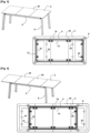
- FIG. 1 presents a rectangular table having a median plane of symmetry arranged in the transverse direction, comprising a top formed of two elements 2, fixed on a flat structure 4 receiving at each corner a foot 6.
- the structure 4 forms a rectangle comprising two side members 10 connected by two cross members 12, these side members and these cross members being formed in the same profile made of aluminum alloy.
- the underside of the tray has a surface for fixing the structure 4 forming a rectangle comprising two longitudinal parts 14 fitting onto the side members 10, two internal transverse parts 18, and two end transverse parts 16 each receiving a cross member 12 of the structure 4.
- the fixing surface of the tray includes recesses 22 which can modularly receive quick fixings 20, which will at the same time clamp an edge of the profiles of this structure and rest on the side of these profiles, to ensure both lateral positioning and effective support of the tray on this structure.
- Each transverse part 16, 18 of the fixing surface of the table top comprises two hollows 22.
- Each longitudinal part 10 of the fixing surface comprises a hollow 22 arranged near the median plane of the table.
- Fasteners 20 are arranged on the hollows 22 of the two transverse end parts 16 and those of the longitudinal parts 14.
- FIG. 2 presents a table with the same structure 4, receiving an extension forming a central element 30 interposed between the two end elements of the top 2.
- Each tray element 2 is fixed by the hollows 22 of the internal transverse part 18 of the fixing surface, and those of the longitudinal parts 14.
- the extension 30 comprises two longitudinal parts 14 of the fixing surface, each comprising a hollow 22 at each end, receiving a fixing 20.
- the same structure 4 is used to quickly fix two or three elements forming the table top.
- the profiles of the structure having a constant section can receive the fixings 20 at any point, which provides great modularity to the table.
- FIG 3 has a long structure 4, receiving the same tray formed of three elements 2, 30 presented figure 2 .
- the crosspieces 12 of the structure 4 are fixed to the end transverse parts 16 of the end elements 2 of the tray, which gives greater stability to this tray.
- FIG 4 has the same long structure 4 of the table presented figure 3 , receiving two central elements 30 forming two extensions intercalated between two end elements of the plate 2.
- the crosspieces 12 of the structure 4 are fixed on the internal transverse parts 18 of the end elements 2.
- FIG. 5 has a table corner comprising two identical section profiles 40 joining to form the corner, formed by an extruded aluminum alloy having a rectangular section arranged vertically, and a rim 42 facing the inside of the table, laid flat under the top.
- the corner connection between the profiles 40 comprises a connecting piece 44 guiding the outer sides of the profiles, and a clamping strip 46 screwed onto the inner sides of these profiles.
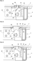
- the fixing 20 comprises a lock 50 rotating along a vertical axis, having an elongated shape transversely arranged in the mounting position shown in this figure, parallel to a crosspiece 12, receiving under a horizontal plate 52 two curved fins 54 aligned along the elongation of the shape, making it possible to apply a manual rotational force to this lock.
- figure 6 presents the lock 50 comprising on the plate 52 successively starting from the top, a central circular shape 66 comprising two opposite lateral bosses 62 each extending over approximately a quarter turn, an upper support plane 60 protruding around this circular shape, then a lower support plane 56 in two parts, covering only the elongated ends of the plate.
- the underside of the bosses 62 has a lower face 64 inclined at 30° relative to the vertical towards the axis of rotation of the lock 50.
- the height between the upper support plane 60 and the lower support plane 56 is equal to the thickness of the edge 42 of the profiles 40.
- Each part of the lower support plane 56 ends towards the front in the direction of the locking rotation, by a slightly inclined face 58 which descends downwards.
- the center of the upper circular shape 66 comprises a bar 72 arranged along a diameter, leaving on each side a hollow each receiving a vertical stud 68 whose upper end protrudes above the upper face of this circular shape.
- FIG. 7 has the hollow 22 formed by machining in the thickness of the tray, over approximately two thirds of this thickness, having a flat bottom. In this way, elements 2, 30 of the tray are obtained having a completely smooth underside, which facilitates packaging, storage or transport.
- the hollow 22 of generally circular shape has on two opposite sides a projection 80 facing the center, each extending over approximately a quarter turn, having an upper face inclined at 30° relative to the vertical axis.
- the lock 50 allows, in a mounting position, to enter the hollow 22 by arranging its lateral bosses 62 between the projections 80, presented figure 7 .
- the upper support plane 60 rests under the flat face of the panel.
- the slightly inclined face 58 of one of the two lower support planes 56 arrives below the edge 42 of the profile 40, this slope forming an entry chamfer facilitating passage under this edge.
- Each elongated part of the lock 50 has a radially external contour 82 comprising an increasing radius, forming a small slope so as to obtain, when rotating this lock, an increasing radius, and a progressive lateral tightening on the edge of the profile 40.
- the studs 68 mounted on the elastic tabs 70 protrude above the upper face of the circular shape 66, compress their tabs by bearing on the bottom of the hollow 22. In this way, an axial pressure is maintained on the lock 50 downwards, by taking up any axial clearances of the bosses 62 above the projections 80, which prevents the free rotation of the lock, in particular by vibrations.
- the locks 50 are also held in this way in the hollows 22 when the structure 4 is not mounted, for example to store the tray with its locks remaining fixed underneath.
- a modular table comprising a number of elements 2, 30 forming the top which can be variable, is obtained simply, quickly and without tools, using profiles 40 having lengths for the side members 10 adjusted to this number of elements.
Landscapes
- Engineering & Computer Science (AREA)
- General Engineering & Computer Science (AREA)
- Mechanical Engineering (AREA)
- Furniture Connections (AREA)
- Tables And Desks Characterized By Structural Shape (AREA)
- Connection Of Plates (AREA)
Claims (10)
- Demontierbarer Tisch, der eine Platte umfasst, die durch Befestigungselemente (20) an einer einen Rahmen bildenden Struktur (4) befestigt ist, wobei die Struktur (4) eine Kante (42) aufweist, die flach unter der Platte liegt, wobei jedes Befestigungselement (20) einen Riegel (50) umfasst, der entlang einer vertikalen Drehachse drehbar ist, mindestens eine Ausbuchtung (62) aufweist, die seitlich vorsteht, und eine Vertiefung (22) umfasst, die in der Dicke der Platte ausgebildet ist und in die Unterseite der Platte mündet, die mindestens einen Vorsprung (80) aufweist, der in der Dicke der Platte ausgebildet ist und zur Drehachse hin gerichtet ist, wobei die mindestens eine Ausbuchtung (62) jedes Riegels (50) in einer Montageposition in die jeweilige Vertiefung (22) neben dem mindestens einen jeweiligen Vorsprung (80) zurückkehrt und in einer Blockierposition nach der Drehung die mindestens eine Ausbuchtung (62) jedes Riegels (50) über den mindestens einen jeweiligen Vorsprung (80) passt, wobei eine untere Auflagefläche (56) jedes Riegels (50) unter die Kante (42) der Struktur (4) kommt.
- Tisch nach Anspruch 1, wobei jeder Riegel (50) zwei gegenüberliegende Ausbuchtungen (62) aufweist, die in der Blockierposition jeweils über einem jeweiligen Vorsprung (80) stehen.
- Tisch nach Anspruch 1 oder 2, wobei jede Ausbuchtung (62) eine Unterseite (64) aufweist, die in Richtung der Drehachse des jeweiligen Riegels (50) geneigt ist, wobei jeder Vorsprung (80) eine Oberseite umfasst, die im gleichen Winkel geneigt ist.
- Tisch nach einem der vorhergehenden Ansprüche, wobei jeder Riegel (50) eine obere Auflagefläche (60) aufweist, die über der jeweiligen unteren Auflagefläche (56) angeordnet ist und an der Unterseite der Platte anliegt.
- Tisch nach einem der vorhergehenden Ansprüche, wobei jeder Riegel (50) entlang einer Querrichtung verlängert ist, wobei jedes Ende jedes Riegels (50) eine untere Auflagefläche (56) aufweist.
- Tisch nach Anspruch 5, wobei jede untere Auflagefläche (56) nach vorne in Richtung der Blockierdrehung durch eine geneigte Fläche (58) endet, die nach unten abfällt.
- Tisch nach einem der vorhergehenden Ansprüche, wobei die radial äußere Kontur (82) jedes Riegels (50) einen zunehmenden Radius aufweist, der während der Blockierdrehung dieses Riegels (50) allmählich auf einer Seite des Rahmens (4) zum Anliegen kommt.
- Tisch nach einem der vorhergehenden Ansprüche, wobei die Oberseite jedes Riegels (50) elastische Zapfen (68) aufweist, die über diese Oberseite hinausragen.
- Tisch nach einem der vorhergehenden Ansprüche, wobei der Rahmen (4) extrudierte Profile (40) aufweist, die die in diesen extrudierten Profilen ausgebildete Kante (42) umfassen.
- Verfahren zum Montieren einer demontierbaren Tischplatte auf einer Struktur (4) durch Befestigungselemente (20), wobei die Struktur (4) eine Kante (42) umfasst, die flach unter der Platte liegt, wobei das Verfahren für jedes Befestigungselement (20) einen Schritt des Einführens eines oberen Teils eines Riegels (50), der entlang einer vertikalen Drehachse drehbar ist, mindestens eine Ausbuchtung (62) umfasst, die seitlich vorsteht, in eine Vertiefung (22), die in der Dicke der Platte ausgebildet ist und in die Unterseite der Platte mündet, die mindestens einen Vorsprung (80) aufweist, der in der Dicke der Platte ausgebildet ist und zur Drehachse hin gerichtet ist, und dann einen Schritt des Drehens des Riegels (50) in Richtung einer Blockierposition umfasst, in der die mindestens eine Ausbuchtung (62) über den mindestens einen jeweiligen Vorsprung (80) eingeführt wird und auf einer unteren Auflagefläche (56) des Riegels (50) unter die Kante (42) der Struktur (4) gleitet.
Applications Claiming Priority (2)
| Application Number | Priority Date | Filing Date | Title |
|---|---|---|---|
| FR1903439A FR3094188B1 (fr) | 2019-04-01 | 2019-04-01 | Table demontable comprenant des fixations rapides du plateau sur une structure |
| PCT/EP2020/059204 WO2020201324A1 (fr) | 2019-04-01 | 2020-04-01 | Table démontable comprenant des fixations rapides du plateau sur une structure |
Publications (3)
| Publication Number | Publication Date |
|---|---|
| EP3945935A1 EP3945935A1 (de) | 2022-02-09 |
| EP3945935C0 EP3945935C0 (de) | 2024-10-09 |
| EP3945935B1 true EP3945935B1 (de) | 2024-10-09 |
Family
ID=67262695
Family Applications (1)
| Application Number | Title | Priority Date | Filing Date |
|---|---|---|---|
| EP20713923.9A Active EP3945935B1 (de) | 2019-04-01 | 2020-04-01 | Zerlegbarer tisch mit schnellbefestigungsmitteln zum befestigen der tischplatte an einer struktur |
Country Status (7)
| Country | Link |
|---|---|
| US (1) | US11751679B2 (de) |
| EP (1) | EP3945935B1 (de) |
| JP (1) | JP7453993B2 (de) |
| CA (1) | CA3132141A1 (de) |
| ES (1) | ES3004514T3 (de) |
| FR (1) | FR3094188B1 (de) |
| WO (1) | WO2020201324A1 (de) |
Families Citing this family (1)
| Publication number | Priority date | Publication date | Assignee | Title |
|---|---|---|---|---|
| US11478073B2 (en) * | 2020-10-20 | 2022-10-25 | Exemplis Llc | Table with removable legs |
Family Cites Families (24)
| Publication number | Priority date | Publication date | Assignee | Title |
|---|---|---|---|---|
| US1795138A (en) * | 1927-11-28 | 1931-03-03 | Remington Rand Inc | Furniture construction |
| US1793709A (en) * | 1928-03-12 | 1931-02-24 | Sun Glow Ind Inc | Furniture |
| US2010394A (en) * | 1931-10-16 | 1935-08-06 | Herman Alexander | Fastening and connection for glass plates |
| US2840431A (en) * | 1951-11-14 | 1958-06-24 | Globe Wernicke Co | Modular office work space and partition structure |
| US2729279A (en) * | 1953-03-02 | 1956-01-03 | Shwayder Brothers | Folding chair seat fastener |
| US2987362A (en) * | 1958-08-22 | 1961-06-06 | Art Woodwork Ltd | Releasable fastening means for parts for an article of furniture |
| GB1170367A (en) * | 1967-06-06 | 1969-11-12 | H C Shepherd & Company Ltd | Improvements in or relating to Articles of Furniture |
| DE3835365A1 (de) * | 1988-10-18 | 1990-04-19 | Gesika Bueromoebelwerk Gmbh | Vorrichtung zum verbinden einer schreibtischplatte mit einem traggestell |
| DE4016486A1 (de) * | 1990-05-22 | 1991-11-28 | Wilkhahn Wilkening & Hahne | Verbindungseinrichtung |
| US5267713A (en) * | 1992-07-20 | 1993-12-07 | Lewis John H | Device for adjusting the height of an article of furniture |
| DE4436166C2 (de) * | 1994-01-28 | 1997-01-09 | Kusch Co Sitzmoebel | Untergestell für Tischplatten für Einzel- und Reihentische |
| DE4402520C1 (de) * | 1994-01-28 | 1995-07-06 | Kusch Co Sitzmoebel | Untergestell für Tischplatten für Einzel- und Reihentische |
| JP2982712B2 (ja) * | 1996-10-21 | 1999-11-29 | コクヨ株式会社 | 天板付き家具 |
| DE29916465U1 (de) * | 1999-09-18 | 2001-02-08 | Dauphin Entwicklungs- u. Beteiligungs-GmbH, 92259 Neukirchen | Tisch-Einheit |
| DE10048777A1 (de) * | 2000-09-29 | 2002-04-18 | Stoll Sedus Ag | Tisch |
| DE202005009719U1 (de) * | 2005-06-21 | 2005-09-08 | Samas Deutschland Gmbh & Co. Kg | Befestigungsanordnung für Möbelteile, insbesondere Tischmöbelteile |
| DE102006021480A1 (de) * | 2006-05-09 | 2007-11-15 | Sedus Stoll Ag | Tischsystem |
| ES2320307B1 (es) * | 2008-12-12 | 2010-07-07 | Sellex S.A. | Armazon de mesa. |
| US8689705B2 (en) * | 2010-06-02 | 2014-04-08 | Steelcase, Inc. | Reconfigurable table assemblies |
| CH705298A1 (de) * | 2011-07-21 | 2013-01-31 | Tecan Trading Ag | Labortisch mit Tischplatten-Elementen. |
| US9578959B2 (en) * | 2011-07-21 | 2017-02-28 | Tecan Trading Ag | Laboratory table having tabletop elements |
| JP5974847B2 (ja) | 2012-11-16 | 2016-08-23 | コクヨ株式会社 | テーブル |
| DE112020004093T5 (de) * | 2019-08-27 | 2022-07-14 | Ergotron, Inc. | Arbeitsplatz mit vereinfachter beinbefestigung |
| US20210100356A1 (en) * | 2019-10-03 | 2021-04-08 | Tung Keng Enterprise Co., Ltd. | Folding support structure |
-
2019
- 2019-04-01 FR FR1903439A patent/FR3094188B1/fr active Active
-
2020
- 2020-04-01 WO PCT/EP2020/059204 patent/WO2020201324A1/fr not_active Ceased
- 2020-04-01 JP JP2021557803A patent/JP7453993B2/ja active Active
- 2020-04-01 ES ES20713923T patent/ES3004514T3/es active Active
- 2020-04-01 US US17/599,783 patent/US11751679B2/en active Active
- 2020-04-01 EP EP20713923.9A patent/EP3945935B1/de active Active
- 2020-04-01 CA CA3132141A patent/CA3132141A1/fr active Pending
Also Published As
| Publication number | Publication date |
|---|---|
| FR3094188B1 (fr) | 2021-03-19 |
| US11751679B2 (en) | 2023-09-12 |
| EP3945935C0 (de) | 2024-10-09 |
| JP2022527485A (ja) | 2022-06-02 |
| CA3132141A1 (fr) | 2020-10-08 |
| WO2020201324A1 (fr) | 2020-10-08 |
| ES3004514T3 (en) | 2025-03-12 |
| FR3094188A1 (fr) | 2020-10-02 |
| EP3945935A1 (de) | 2022-02-09 |
| US20220142355A1 (en) | 2022-05-12 |
| JP7453993B2 (ja) | 2024-03-21 |
Similar Documents
| Publication | Publication Date | Title |
|---|---|---|
| FR3098381A1 (fr) | Dispositif de raccordement pour accessoires de rayonnage métalliques modulaires | |
| FR2773534A1 (fr) | Boite empilable et demontable | |
| EP0725464A1 (de) | Sockel für einen Schaltschrank oder dergleichen und Schrank mit einen solchen Sockel | |
| EP3945935B1 (de) | Zerlegbarer tisch mit schnellbefestigungsmitteln zum befestigen der tischplatte an einer struktur | |
| EP0900037A1 (de) | Zusammensetzbarer stuhl | |
| FR2549933A1 (fr) | Poutre profilee en forme d'i, attaches et assemblages pour de telles poutres | |
| FR2930124A1 (fr) | Meuble demontable | |
| EP2767499A1 (de) | Laschenverbindungsvorrichtung zur Verbindung von zwei Mastelementen, und Anordnung, die zwei Mastelemente und solche Laschenverbindungsvorrichtungen umfasst | |
| FR3069143A1 (fr) | Un plateau support d'un outil pour appareil de preparation culinaire et appareil de preparation culinaire le comportant | |
| FR2683566A1 (fr) | Dispositif de support en tole pour un profile horizontal destine a recevoir un faux plafond. | |
| CH419967A (fr) | Cadre pour la manutention, le transport et le stockage d'une matière en feuilles | |
| BE1013770A5 (fr) | Boite empilable et demontable. | |
| FR2631066A1 (en) | Tying device for formworking, and formwork for concrete stanchions | |
| FR2553646A1 (fr) | Echelles ou chassis plan pour etageres | |
| EP0595744A1 (de) | Zerlegbare und stapelbare Palette, insbesondere für plattenförmige Produkte | |
| WO1990000684A1 (fr) | Systeme d'assemblage pour la realisation d'objets divers du type meuble notamment | |
| FR2571341A1 (fr) | Dispositif de rassemblement, notamment pour objets allonges | |
| BE536596A (de) | ||
| FR2478977A1 (fr) | Table a tapisser | |
| EP1386304B1 (de) | Profil und satz von mehreren elementen mit einem oder mehreren solcher profilen | |
| FR2782309A1 (fr) | Palette de stockage et de transport d'elements longilignes | |
| FR2744096A1 (fr) | Conteneur caisse palette monobloc | |
| FR2590929A1 (fr) | Marchepied demontable | |
| FR2886823A1 (fr) | Meuble a etageres | |
| FR2746432A1 (fr) | Dispositif de support pour un agencement formant plancher sur des parois peripheriques d'une structure |
Legal Events
| Date | Code | Title | Description |
|---|---|---|---|
| STAA | Information on the status of an ep patent application or granted ep patent |
Free format text: STATUS: UNKNOWN |
|
| STAA | Information on the status of an ep patent application or granted ep patent |
Free format text: STATUS: THE INTERNATIONAL PUBLICATION HAS BEEN MADE |
|
| PUAI | Public reference made under article 153(3) epc to a published international application that has entered the european phase |
Free format text: ORIGINAL CODE: 0009012 |
|
| STAA | Information on the status of an ep patent application or granted ep patent |
Free format text: STATUS: REQUEST FOR EXAMINATION WAS MADE |
|
| 17P | Request for examination filed |
Effective date: 20211025 |
|
| AK | Designated contracting states |
Kind code of ref document: A1 Designated state(s): AL AT BE BG CH CY CZ DE DK EE ES FI FR GB GR HR HU IE IS IT LI LT LU LV MC MK MT NL NO PL PT RO RS SE SI SK SM TR |
|
| DAV | Request for validation of the european patent (deleted) | ||
| DAX | Request for extension of the european patent (deleted) | ||
| STAA | Information on the status of an ep patent application or granted ep patent |
Free format text: STATUS: EXAMINATION IS IN PROGRESS |
|
| 17Q | First examination report despatched |
Effective date: 20230710 |
|
| GRAP | Despatch of communication of intention to grant a patent |
Free format text: ORIGINAL CODE: EPIDOSNIGR1 |
|
| STAA | Information on the status of an ep patent application or granted ep patent |
Free format text: STATUS: GRANT OF PATENT IS INTENDED |
|
| INTG | Intention to grant announced |
Effective date: 20240507 |
|
| GRAS | Grant fee paid |
Free format text: ORIGINAL CODE: EPIDOSNIGR3 |
|
| GRAA | (expected) grant |
Free format text: ORIGINAL CODE: 0009210 |
|
| STAA | Information on the status of an ep patent application or granted ep patent |
Free format text: STATUS: THE PATENT HAS BEEN GRANTED |
|
| AK | Designated contracting states |
Kind code of ref document: B1 Designated state(s): AL AT BE BG CH CY CZ DE DK EE ES FI FR GB GR HR HU IE IS IT LI LT LU LV MC MK MT NL NO PL PT RO RS SE SI SK SM TR |
|
| REG | Reference to a national code |
Ref country code: CH Ref legal event code: EP |
|
| REG | Reference to a national code |
Ref country code: DE Ref legal event code: R096 Ref document number: 602020039014 Country of ref document: DE |
|
| REG | Reference to a national code |
Ref country code: IE Ref legal event code: FG4D Free format text: LANGUAGE OF EP DOCUMENT: FRENCH |
|
| U01 | Request for unitary effect filed |
Effective date: 20241104 |
|
| U07 | Unitary effect registered |
Designated state(s): AT BE BG DE DK EE FI FR IT LT LU LV MT NL PT RO SE SI Effective date: 20241113 |
|
| REG | Reference to a national code |
Ref country code: ES Ref legal event code: FG2A Ref document number: 3004514 Country of ref document: ES Kind code of ref document: T3 Effective date: 20250312 |
|
| PG25 | Lapsed in a contracting state [announced via postgrant information from national office to epo] |
Ref country code: HR Free format text: LAPSE BECAUSE OF FAILURE TO SUBMIT A TRANSLATION OF THE DESCRIPTION OR TO PAY THE FEE WITHIN THE PRESCRIBED TIME-LIMIT Effective date: 20241009 Ref country code: IS Free format text: LAPSE BECAUSE OF FAILURE TO SUBMIT A TRANSLATION OF THE DESCRIPTION OR TO PAY THE FEE WITHIN THE PRESCRIBED TIME-LIMIT Effective date: 20250209 |
|
| PG25 | Lapsed in a contracting state [announced via postgrant information from national office to epo] |
Ref country code: GR Free format text: LAPSE BECAUSE OF FAILURE TO SUBMIT A TRANSLATION OF THE DESCRIPTION OR TO PAY THE FEE WITHIN THE PRESCRIBED TIME-LIMIT Effective date: 20250110 |
|
| PG25 | Lapsed in a contracting state [announced via postgrant information from national office to epo] |
Ref country code: PL Free format text: LAPSE BECAUSE OF FAILURE TO SUBMIT A TRANSLATION OF THE DESCRIPTION OR TO PAY THE FEE WITHIN THE PRESCRIBED TIME-LIMIT Effective date: 20241009 |
|
| PG25 | Lapsed in a contracting state [announced via postgrant information from national office to epo] |
Ref country code: RS Free format text: LAPSE BECAUSE OF FAILURE TO SUBMIT A TRANSLATION OF THE DESCRIPTION OR TO PAY THE FEE WITHIN THE PRESCRIBED TIME-LIMIT Effective date: 20250109 |
|
| U21 | Renewal fee for the european patent with unitary effect paid with additional fee |
Year of fee payment: 6 Effective date: 20250522 |
|
| PG25 | Lapsed in a contracting state [announced via postgrant information from national office to epo] |
Ref country code: SM Free format text: LAPSE BECAUSE OF FAILURE TO SUBMIT A TRANSLATION OF THE DESCRIPTION OR TO PAY THE FEE WITHIN THE PRESCRIBED TIME-LIMIT Effective date: 20241009 |
|
| PGFP | Annual fee paid to national office [announced via postgrant information from national office to epo] |
Ref country code: NO Payment date: 20250422 Year of fee payment: 6 |
|
| PGFP | Annual fee paid to national office [announced via postgrant information from national office to epo] |
Ref country code: CH Payment date: 20250501 Year of fee payment: 6 |
|
| PG25 | Lapsed in a contracting state [announced via postgrant information from national office to epo] |
Ref country code: SK Free format text: LAPSE BECAUSE OF FAILURE TO SUBMIT A TRANSLATION OF THE DESCRIPTION OR TO PAY THE FEE WITHIN THE PRESCRIBED TIME-LIMIT Effective date: 20241009 |
|
| PG25 | Lapsed in a contracting state [announced via postgrant information from national office to epo] |
Ref country code: CZ Free format text: LAPSE BECAUSE OF FAILURE TO SUBMIT A TRANSLATION OF THE DESCRIPTION OR TO PAY THE FEE WITHIN THE PRESCRIBED TIME-LIMIT Effective date: 20241009 |
|
| PLBE | No opposition filed within time limit |
Free format text: ORIGINAL CODE: 0009261 |
|
| STAA | Information on the status of an ep patent application or granted ep patent |
Free format text: STATUS: NO OPPOSITION FILED WITHIN TIME LIMIT |
|
| 26N | No opposition filed |
Effective date: 20250710 |
|
| PGFP | Annual fee paid to national office [announced via postgrant information from national office to epo] |
Ref country code: ES Payment date: 20250715 Year of fee payment: 6 |
|
| PG25 | Lapsed in a contracting state [announced via postgrant information from national office to epo] |
Ref country code: MC Free format text: LAPSE BECAUSE OF FAILURE TO SUBMIT A TRANSLATION OF THE DESCRIPTION OR TO PAY THE FEE WITHIN THE PRESCRIBED TIME-LIMIT Effective date: 20241009 |
|
| U20 | Renewal fee for the european patent with unitary effect paid |
Year of fee payment: 7 Effective date: 20260213 |
|
| PGFP | Annual fee paid to national office [announced via postgrant information from national office to epo] |
Ref country code: GB Payment date: 20260227 Year of fee payment: 7 |
|
| PG25 | Lapsed in a contracting state [announced via postgrant information from national office to epo] |
Ref country code: IE Free format text: LAPSE BECAUSE OF NON-PAYMENT OF DUE FEES Effective date: 20250401 |