EP3944359B1 - Batteriemodul - Google Patents
Batteriemodul Download PDFInfo
- Publication number
- EP3944359B1 EP3944359B1 EP19921804.1A EP19921804A EP3944359B1 EP 3944359 B1 EP3944359 B1 EP 3944359B1 EP 19921804 A EP19921804 A EP 19921804A EP 3944359 B1 EP3944359 B1 EP 3944359B1
- Authority
- EP
- European Patent Office
- Prior art keywords
- plate
- duct
- cover plate
- battery
- gas discharge
- Prior art date
- Legal status (The legal status is an assumption and is not a legal conclusion. Google has not performed a legal analysis and makes no representation as to the accuracy of the status listed.)
- Active
Links
Images


Classifications
-
- H—ELECTRICITY
- H01—ELECTRIC ELEMENTS
- H01M—PROCESSES OR MEANS, e.g. BATTERIES, FOR THE DIRECT CONVERSION OF CHEMICAL ENERGY INTO ELECTRICAL ENERGY
- H01M10/00—Secondary cells; Manufacture thereof
- H01M10/60—Heating or cooling; Temperature control
- H01M10/61—Types of temperature control
- H01M10/613—Cooling or keeping cold
-
- H—ELECTRICITY
- H01—ELECTRIC ELEMENTS
- H01M—PROCESSES OR MEANS, e.g. BATTERIES, FOR THE DIRECT CONVERSION OF CHEMICAL ENERGY INTO ELECTRICAL ENERGY
- H01M10/00—Secondary cells; Manufacture thereof
- H01M10/60—Heating or cooling; Temperature control
- H01M10/62—Heating or cooling; Temperature control specially adapted for specific applications
- H01M10/625—Vehicles
-
- H—ELECTRICITY
- H01—ELECTRIC ELEMENTS
- H01M—PROCESSES OR MEANS, e.g. BATTERIES, FOR THE DIRECT CONVERSION OF CHEMICAL ENERGY INTO ELECTRICAL ENERGY
- H01M10/00—Secondary cells; Manufacture thereof
- H01M10/60—Heating or cooling; Temperature control
- H01M10/65—Means for temperature control structurally associated with the cells
- H01M10/655—Solid structures for heat exchange or heat conduction
- H01M10/6554—Rods or plates
-
- H—ELECTRICITY
- H01—ELECTRIC ELEMENTS
- H01M—PROCESSES OR MEANS, e.g. BATTERIES, FOR THE DIRECT CONVERSION OF CHEMICAL ENERGY INTO ELECTRICAL ENERGY
- H01M50/00—Constructional details or processes of manufacture of the non-active parts of electrochemical cells other than fuel cells, e.g. hybrid cells
- H01M50/20—Mountings; Secondary casings or frames; Racks, modules or packs; Suspension devices; Shock absorbers; Transport or carrying devices; Holders
- H01M50/204—Racks, modules or packs for multiple batteries or multiple cells
- H01M50/207—Racks, modules or packs for multiple batteries or multiple cells characterised by their shape
- H01M50/209—Racks, modules or packs for multiple batteries or multiple cells characterised by their shape adapted for prismatic or rectangular cells
-
- H—ELECTRICITY
- H01—ELECTRIC ELEMENTS
- H01M—PROCESSES OR MEANS, e.g. BATTERIES, FOR THE DIRECT CONVERSION OF CHEMICAL ENERGY INTO ELECTRICAL ENERGY
- H01M50/00—Constructional details or processes of manufacture of the non-active parts of electrochemical cells other than fuel cells, e.g. hybrid cells
- H01M50/20—Mountings; Secondary casings or frames; Racks, modules or packs; Suspension devices; Shock absorbers; Transport or carrying devices; Holders
- H01M50/218—Mountings; Secondary casings or frames; Racks, modules or packs; Suspension devices; Shock absorbers; Transport or carrying devices; Holders characterised by the material
- H01M50/22—Mountings; Secondary casings or frames; Racks, modules or packs; Suspension devices; Shock absorbers; Transport or carrying devices; Holders characterised by the material of the casings or racks
- H01M50/222—Inorganic material
- H01M50/224—Metals
-
- H—ELECTRICITY
- H01—ELECTRIC ELEMENTS
- H01M—PROCESSES OR MEANS, e.g. BATTERIES, FOR THE DIRECT CONVERSION OF CHEMICAL ENERGY INTO ELECTRICAL ENERGY
- H01M50/00—Constructional details or processes of manufacture of the non-active parts of electrochemical cells other than fuel cells, e.g. hybrid cells
- H01M50/20—Mountings; Secondary casings or frames; Racks, modules or packs; Suspension devices; Shock absorbers; Transport or carrying devices; Holders
- H01M50/249—Mountings; Secondary casings or frames; Racks, modules or packs; Suspension devices; Shock absorbers; Transport or carrying devices; Holders specially adapted for aircraft or vehicles, e.g. cars or trains
-
- H—ELECTRICITY
- H01—ELECTRIC ELEMENTS
- H01M—PROCESSES OR MEANS, e.g. BATTERIES, FOR THE DIRECT CONVERSION OF CHEMICAL ENERGY INTO ELECTRICAL ENERGY
- H01M50/00—Constructional details or processes of manufacture of the non-active parts of electrochemical cells other than fuel cells, e.g. hybrid cells
- H01M50/20—Mountings; Secondary casings or frames; Racks, modules or packs; Suspension devices; Shock absorbers; Transport or carrying devices; Holders
- H01M50/262—Mountings; Secondary casings or frames; Racks, modules or packs; Suspension devices; Shock absorbers; Transport or carrying devices; Holders with fastening means, e.g. locks
-
- H—ELECTRICITY
- H01—ELECTRIC ELEMENTS
- H01M—PROCESSES OR MEANS, e.g. BATTERIES, FOR THE DIRECT CONVERSION OF CHEMICAL ENERGY INTO ELECTRICAL ENERGY
- H01M50/00—Constructional details or processes of manufacture of the non-active parts of electrochemical cells other than fuel cells, e.g. hybrid cells
- H01M50/20—Mountings; Secondary casings or frames; Racks, modules or packs; Suspension devices; Shock absorbers; Transport or carrying devices; Holders
- H01M50/271—Lids or covers for the racks or secondary casings
-
- H—ELECTRICITY
- H01—ELECTRIC ELEMENTS
- H01M—PROCESSES OR MEANS, e.g. BATTERIES, FOR THE DIRECT CONVERSION OF CHEMICAL ENERGY INTO ELECTRICAL ENERGY
- H01M50/00—Constructional details or processes of manufacture of the non-active parts of electrochemical cells other than fuel cells, e.g. hybrid cells
- H01M50/30—Arrangements for facilitating escape of gases
- H01M50/342—Non-re-sealable arrangements
- H01M50/3425—Non-re-sealable arrangements in the form of rupturable membranes or weakened parts, e.g. pierced with the aid of a sharp member
-
- H—ELECTRICITY
- H01—ELECTRIC ELEMENTS
- H01M—PROCESSES OR MEANS, e.g. BATTERIES, FOR THE DIRECT CONVERSION OF CHEMICAL ENERGY INTO ELECTRICAL ENERGY
- H01M50/00—Constructional details or processes of manufacture of the non-active parts of electrochemical cells other than fuel cells, e.g. hybrid cells
- H01M50/30—Arrangements for facilitating escape of gases
- H01M50/35—Gas exhaust passages comprising elongated, tortuous or labyrinth-shaped exhaust passages
- H01M50/358—External gas exhaust passages located on the battery cover or case
-
- H—ELECTRICITY
- H01—ELECTRIC ELEMENTS
- H01M—PROCESSES OR MEANS, e.g. BATTERIES, FOR THE DIRECT CONVERSION OF CHEMICAL ENERGY INTO ELECTRICAL ENERGY
- H01M50/00—Constructional details or processes of manufacture of the non-active parts of electrochemical cells other than fuel cells, e.g. hybrid cells
- H01M50/30—Arrangements for facilitating escape of gases
- H01M50/35—Gas exhaust passages comprising elongated, tortuous or labyrinth-shaped exhaust passages
- H01M50/367—Internal gas exhaust passages forming part of the battery cover or case; Double cover vent systems
-
- H—ELECTRICITY
- H01—ELECTRIC ELEMENTS
- H01M—PROCESSES OR MEANS, e.g. BATTERIES, FOR THE DIRECT CONVERSION OF CHEMICAL ENERGY INTO ELECTRICAL ENERGY
- H01M2220/00—Batteries for particular applications
- H01M2220/20—Batteries in motive systems, e.g. vehicle, ship, plane
-
- Y—GENERAL TAGGING OF NEW TECHNOLOGICAL DEVELOPMENTS; GENERAL TAGGING OF CROSS-SECTIONAL TECHNOLOGIES SPANNING OVER SEVERAL SECTIONS OF THE IPC; TECHNICAL SUBJECTS COVERED BY FORMER USPC CROSS-REFERENCE ART COLLECTIONS [XRACs] AND DIGESTS
- Y02—TECHNOLOGIES OR APPLICATIONS FOR MITIGATION OR ADAPTATION AGAINST CLIMATE CHANGE
- Y02E—REDUCTION OF GREENHOUSE GAS [GHG] EMISSIONS, RELATED TO ENERGY GENERATION, TRANSMISSION OR DISTRIBUTION
- Y02E60/00—Enabling technologies; Technologies with a potential or indirect contribution to GHG emissions mitigation
- Y02E60/10—Energy storage using batteries
Definitions
- the present invention relates to a battery module.
- each of the batteries that form the battery module is provided with a valve portion that opens in response to an increase in inner pressure.
- a gas is generated in a battery due to a chemical reaction so that an inner pressure in the battery is increased, a gas having a high temperature and a high pressure is blown off from a valve portion.
- PTL 1 discloses a battery module which includes: a battery stack in which a plurality of batteries are stacked; and a gas discharge duct which is fixed to one surface of the battery stack in such a manner that the gas discharge duct is connected to the valve portions of the respective batteries.
- the document JP2015211025 discloses a power storage device
- the document JP2015135763 discloses a power storage device
- the document KR20170069003 discloses a battery module.
- the present invention has been made in view of such circumstances, and it is an object of the present invention to provide a technique which can enhance safety of a battery module.
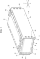
- the battery module includes: a battery stack including a plurality of batteries that are stacked, each of the plurality of batteries having a valve portion through which a gas is blown off; a duct plate configured to cover a surface of the battery stack on which a plurality of the valve portions are disposed, the duct plate having a gas discharge duct that extends in a stacking direction of the batteries, is connected to the valve portions of the respective batteries, and temporarily stores a blown-off gas; a cover plate placed on the duct plate; and a flow path portion defined by the duct plate and the cover plate, the flow path portion extending from the gas discharge duct in a first direction that intersects with the stacking direction of the batteries and allowing leaking of the gas in the gas discharge duct to an outside of the battery module.
- the cover plate is disposed in a state where a predetermined gap is formed between the cover plate and a first wall portion of the gas discharge duct that faces the valve portion, and an opening that allows an inside of the gas discharge duct and the gap to communicate with each other is formed in the first wall portion of the gas discharge duct.
- the safety of a battery module can be enhanced.
- Output terminal 22 of a positive electrode is disposed on sealing plate 20 at a position close to one end of sealing plate 20 in a longitudinal direction
- output terminal 22 of a negative electrode is disposed on sealing plate 20 at a position close to the other end of sealing plate 20 in the longitudinal direction.
- the pair of output terminals 22 is respectively electrically connected to positive electrode plates and negative electrode plates that form the electrode assembly.
- output terminal 22 of the positive electrode is referred to as positive electrode terminal 22a
- output terminal 22 of the negative electrode is referred to as negative electrode terminal 22b as appropriate.
- positive electrode terminal 22a and negative electrode terminal 22b are collectively referred to as output terminals 22.
- Exterior can 18, sealing plate 20, and output terminals 22 are electric conductors and are made of metal, for example. Sealing plate 20 and the opening of exterior can 18 are joined to each other by, for example, laser welding. Respective output terminals 22 are inserted into through holes (not illustrated) formed in sealing plate 20. A seal member (not illustrated) having insulating property is interposed between respective output terminals 22 and respective through holes.
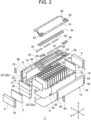
- Each end plate 4 has fastening holes 4a on two surfaces that are directed in horizontal direction Y.
- three fastening holes 4a are disposed at a predetermined interval in vertical direction Z.
- the surface where fastening holes 4a are formed faces flat surface portion 54 of constraining member 12. Flat surface portion 54 will be described later.
- the plurality of batteries 14 are sandwiched between end plates 4 in stacking direction X.
- battery stack 2 is formed by alternately arranging the plurality of batteries 14 and the plurality of inter-cell separators 16, and such battery stack 2 is sandwiched between the pair of end plates 4 with external end separators 5 sandwiched between battery stack 2 and end plates 4 in stacking direction X.
- Heat conductive layer 8 is disposed below the lower surface of battery stack 2 and, further, cooling plate 6 is disposed so as to face battery stack 2 with heat conductive layer 8 interposed between cooling plate 6 and battery stack 2.
- battery stack 2 the pair of end plates 4, cooling plate 6, and heat conductive layer 8 are sandwiched between the pair of side separators 10 in horizontal direction Y. Further, the pair of constraining members 12 sandwiches the whole body in horizontal direction Y from the outside of the pair of side separators 10.
- the pair of end plates 4 and the pair of constraining members 12 are aligned with each other such that fastening holes 4a, through holes 70, and through holes 58 overlap with each other.
- Fastening members 59 such as screws are made to pass through through holes 58 and through holes 70 and are made to threadedly engage with fastening holes 4a.
- the pair of end plates 4 and the pair of constraining members 12 are fixed to each other.
- the plurality of batteries 14 are fastened to each other and are constrained in stacking direction X. Accordingly, respective batteries 14 are positioned in stacking direction X.
- Constraining members 12 sandwich the plurality of batteries 14 in stacking direction X. Constraining members 12 also sandwich battery stack 2, heat conductive layer 8, and cooling plate 6 in the arrangement direction of battery stack 2, heat conductive layer 8, and cooling plate 6. Specifically, constraining members 12 sandwich the plurality of batteries 14 in stacking direction X in such a manner that both end portions of flat surface portions 54 of constraining members 12 in stacking direction X of batteries 14 engage with the pair of end plates 4. Battery stack 2, heat conductive layer 8, and cooling plate 6 are sandwiched between the pair of arm portions 56 of constraining members 12 in vertical direction Z. That is, constraining members 12 have both a function of fastening the plurality of batteries 14 and a function of fastening battery stack 2 and cooling plate 6. Therefore, unlike the conventional structure, battery stack 2 and cooling plate 6 are not fastened by screws.
- heat conductive layer 8 is elastically deformed or plastically deformed by being pressed by battery stack 2 and cooling plate 6. Consequently, it is possible to obtain thermal connection between battery stack 2 and cooling plate 6 with more certainty. In addition, entire battery stack 2 can be cooled uniformly. Further, deviation between battery stack 2 and cooling plate 6 in the XY plane direction can be further suppressed.
- duct plate 28 is placed on battery stack 2.
- duct plate 28 is fixed to battery stack 2 by making third portions 53 of the pair of side separators 10 engage with duct plate 28.
- bus bars 42 are mounted on output terminals 22 of respective batteries 14 so that output terminals 22 of the plurality of batteries 14 are electrically connected to each other.
- bus bars 42 are fixed to output terminals 22 by welding.
- Cover plate 60 is placed on an upper surface of duct plate 28.
- Cover plate 60 is a plate-shaped member that covers duct plate 28 from above.
- Cover plate 60 according to the present exemplary embodiment is a so-called top cover that forms a portion of an outer shell of battery module 1, specifically, the upper surface of battery module 1.
- Cover plate 60 prevents dew condensation water, dust, or the like from being brought into contact with output terminals 22, valve portions 24 of batteries 14, bus bars 42 and the like.
- Cover plate 60 is made of a resin having an insulating property, for example.
- Cover plate 60 has insulating cover portions 62 at position overlapping with external connection terminals 44 in vertical direction Z.
- Both end portions of cover plate 60 in the first direction are fixed to duct plate 28.
- Cover plate 60 of the present exemplary embodiment is fixed to duct plate 28 by snap-fitting.
- duct plate 28 has a plurality of engaging claws 72 at both end portions of duct plate 28 in horizontal direction Y in a state where the plurality of engaging claws 72 are disposed at an interval in stacking direction X.
- Cover plate 60 has engaging holes 74 at positions overlapping with respective engaging claws 72 when viewed in vertical direction Z. Engaging claw 72 and engaging hole 74 form snap-fit portion 71 (see FIGS. 3 and 4 ).
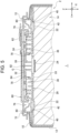
- FIG. 3 is a cross-sectional side view of a region in which duct plate 28 and cover plate 60 of battery module 1 are disposed.
- FIG. 4 is a cross-sectional perspective view of the region in which duct plate 28 and cover plate 60 of battery module 1 are disposed. In FIG. 3 and FIG. 4 , illustration of an internal structure of battery 14 is omitted.
- Battery module 1 includes flow path portions 76.
- Flow path portions 76 are flow paths that allow a gas in gas discharge duct 38 to leak to the outside of battery module 1.
- Flow path portions 76 are defined by duct plate 28 and cover plate 60, and extend from gas discharge duct 38 in the first direction (horizontal direction Y) intersecting with stacking direction X.
- Flow path portions 76 are disposed on both sides in horizontal direction Y with gas discharge duct 38 sandwiched between flow path portions 76.
- Respective flow path portions 76 are connected to second wall portions 36 directed in horizontal direction Y of gas discharge duct 38. More specifically, opening 78 is formed in each of second wall portions 36, and one end portion of each of flow path portions 76 is connected to opening 78.
- the other end portions of respective flow path portions 76 are connected to flow path outlets 80 disposed at the end portions of battery module 1 in horizontal direction Y.
- the plurality of openings 78 are formed in second wall portion 36 at a predetermined interval in stacking direction X, and one end portion of flow path portion 76 is connected to the plurality of openings 78.
- Flow path outlet 80 is an opening that is elongated in stacking direction X. Therefore, flow path portion 76 is a planar flow path that expands in stacking direction X and horizontal direction Y.
- Cover plate 60 is disposed in a state where predetermined gap G is formed between cover plate 60 and first wall portion 34 that faces valve portion 24 of gas discharge duct 38. That is, first wall portion 34 and cover plate 60 are spaced apart from each other in vertical direction Z by gap G. Openings 82 which allow the inside of gas discharge duct 38 and gap G to communicate with each other are formed in first wall portion 34 of gas discharge duct 38. In the present exemplary embodiment, the plurality of openings 82 are uniformly arranged over entire first wall portion 34 (see FIG. 2 ). Further, both end portions of gap G in horizontal direction Y are connected to flow path portions 76.
- gas discharge duct 38 and flow path portions 76 communicate with each other not only through openings 78 formed in second wall portions 36 but also through openings 82 formed in first wall portion 34 and gap G.
- Opening 82 can be formed by, for example, punching a metal plate constituting first wall portion 34.
- At least a portion of the gas blown off from battery 14 is a combustible gas.
- the gas blown off from battery 14 also contains fine particles such as broken pieces of a battery structure.
- a gas blown off from valve portion 24 is once received by gas discharge duct 38, and then is discharged to the outside of battery module 1 through flow path portion 76. As a result, the temperature of the gas and the temperature of the fine particles can be lowered until the gas or the fine particles are released to the outside of battery module 1.
- Engaging claw 72 of snap-fit portion 71 has support strut portion 72a and protruding portion 72b.
- Support strut portion 72a extends in vertical direction Z along which duct plate 28 and cover plate 60 are arranged.
- Protruding portion 72b protrudes from support strut portion 72a toward the opposite of gas discharge duct 38 at a distal end of support strut portion 72a. That is, in horizontal direction Y, gas discharge duct 38 is disposed at a center portion of battery module 1, and protruding portions 72b protrude toward the outside of battery module 1.
- Duct plate 28 and cover plate 60 are fixed to each other in such a manner that engaging claws 72 are inserted into engaging holes 74 and protruding portions 72b are caught by peripheral edge portions of engaging holes 74.
Landscapes
- Chemical & Material Sciences (AREA)
- Chemical Kinetics & Catalysis (AREA)
- Electrochemistry (AREA)
- General Chemical & Material Sciences (AREA)
- Engineering & Computer Science (AREA)
- Manufacturing & Machinery (AREA)
- Inorganic Chemistry (AREA)
- Aviation & Aerospace Engineering (AREA)
- Battery Mounting, Suspending (AREA)
- Gas Exhaust Devices For Batteries (AREA)
Claims (6)
- Batteriemodul (1), das Folgendes umfasst:einen Batteriestapel (2), der eine Vielzahl von Batterien (14) beinhaltet, die gestapelt sind, wobei die Vielzahl von Batterien (14) die Vielzahl von Ventilen (24) beinhalten, durch die ein Gas abgeblasen wird, wobei die Batterien prismatisch sind,eine Kanalplatte (28), die dazu ausgelegt ist, eine Fläche des Batteriestapels (2) abzudecken, auf der die Vielzahl der Ventile (24) angeordnet sind, wobei die Kanalplatte (28) einen Gasaustrittskanal (38) beinhaltet, der sich in einer Stapelrichtung (X) der Batterien (14) erstreckt, mit den Ventilen der Batterien (14) verbunden ist und vorübergehend das Gas, das aus den Ventilen (24) abgeblasen wird, speichert;eine Abdeckplatte (60) die auf der Kanalplatte (28) platziert ist; undeinen Strömungspfadabschnitt (76), der von der Kanalplatte (28) und der Abdeckplatte (60) definiert wird, wobei sich der Strömungspfadabschnitt (76) vom Gasaustrittskanal (38) in eine erste Richtung, die die Stapelrichtung (X) der Batterien (14) schneidet, erstreckt und ein Entweichen des Gases im Gasaustrittskanal (38) zu einer Außenseite des Batteriemoduls (1) erlaubt, wobei die erste Richtung eine horizontale Richtung (Y) ist,Strömungspfadauslässe (80), die mit dem Strömungspfad (76) verbunden und in der horizontalen Richtung (Y) an Endabschnitten des Batteriemoduls (1) angeordnet sind und durch die Gas austritt,wobei die Abdeckplatte (60) in einem Zustand angeordnet ist, in dem ein vorbestimmter Spalt (G) zwischen der Abdeckplatte (60) und einer ersten Wand (34) des Gasaustrittskanals (38) ausgelegt ist, die den Ventilen (24) zugewandt ist, derart, dass die erste Wand (34) und die Abdeckplatte (60) in einer vertikalen Richtung Z durch den vorbestimmten Spalt (G) voneinander beabstandet sind, undeine Öffnung (82), die es erlaubt, dass eine Innenseite des Gasaustrittskanals (38) und der vorbestimmte Spalt (G) miteinander kommunizieren, ist in der ersten Wand (34) des Gasaustrittskanals (38) ausgelegt,wobei die Kanalplatte (28) ein Paar von zweiten Wänden (36) beinhaltet, das Seite an Seite mit dem Ventil (24) angebracht ist, das zwischen dem Paar von zweiten Wänden (36) eingefügt ist, und zusammen mit der ersten Wand (34) den Gasaustrittskanal (38) definiert, undeine Öffnung (78), die es erlaubt, dass der Gasaustrittskanal (38) und der Strömungspfad (76) miteinander kommunizieren, ist jeweils im Paar von zweiten Wänden (36) ausgelegt.
- Batteriemodul (1) nach Anspruch 1, wobei die erste Wand (34) aus einer Metallplatte gebildet ist.
- Batteriemodul (1) nach einem von Anspruch 1 bis Anspruch 2, wobei in einer Region, die sich in einer Richtung gesehen, in der die Kanalplatte (28) und die Abdeckplatte (60) angebracht sind, mit der Öffnung überlappt, die Abdeckplatte (60) eine Wärmeübertragungsunterdrückungsschicht (84) beinhaltet, die eine Wärmeübertragung vom Gas zur Abdeckplatte (60) unterdrückt.
- Batteriemodul (1) nach einem von Anspruch 1 bis Anspruch 3, wobei beide Enden der Abdeckplatte (60) in der ersten Richtung an der Kanalplatte (28) befestigt sind, und
der Gasaustrittskanal (38) ist in einer Position angeordnet, die sich in der ersten Richtung mit einem mittleren Teil der Abdeckplatte (60) überlappt. - Batteriemodul (1) nach einem von Anspruch 1 bis Anspruch 4, das ferner ein Schnappverbindungsteil (71) umfasst, das aus einer Eingriffsklaue (72) und einem Eingriffsloch (74) ausgelegt ist, die ineinander eingreifen, wobei das Schnappverbindungsteil dazu ausgelegt ist, die Kanalplatte (28) und die Abdeckplatte (60) aneinander zu befestigen, wobei die Eingriffsklaue Folgendes beinhaltet:ein Stützstrebenteil (72a), das sich in eine Richtung erstreckt, in der die Kanalplatte (28) und die Abdeckplatte (60) angebracht sind; undein vorstehendes Teil (72b), das vom Stützstrebenteil zur gegenüberliegenden Seite des Gasaustrittskanals (38) vorsteht, unddie Kanalplatte (28) und die Abdeckplatte (60) dazu ausgelegt sind, in einer derartigen Weise aneinander befestigt zu sein, dass die Eingriffsklaue in das Eingriffsloch eingesetzt wird und das vorstehende Teil von der Peripheriekante des Eingriffslochs ergriffen wird.
- Batteriemodul (1) nach einem von Anspruch 1 bis Anspruch 5, wobei beide Endabschnitte des vorbestimmten Spalts (G) in der horizontalen Richtung Y mit Strömungspfadabschnitten (76) verbunden sind.
Applications Claiming Priority (2)
| Application Number | Priority Date | Filing Date | Title |
|---|---|---|---|
| JP2019054578 | 2019-03-22 | ||
| PCT/JP2019/051124 WO2020194966A1 (ja) | 2019-03-22 | 2019-12-26 | 電池モジュール |
Publications (3)
| Publication Number | Publication Date |
|---|---|
| EP3944359A1 EP3944359A1 (de) | 2022-01-26 |
| EP3944359A4 EP3944359A4 (de) | 2022-05-18 |
| EP3944359B1 true EP3944359B1 (de) | 2025-02-26 |
Family
ID=72611346
Family Applications (1)
| Application Number | Title | Priority Date | Filing Date |
|---|---|---|---|
| EP19921804.1A Active EP3944359B1 (de) | 2019-03-22 | 2019-12-26 | Batteriemodul |
Country Status (5)
| Country | Link |
|---|---|
| US (1) | US12087964B2 (de) |
| EP (1) | EP3944359B1 (de) |
| JP (1) | JP7418410B2 (de) |
| CN (1) | CN113632297B (de) |
| WO (1) | WO2020194966A1 (de) |
Families Citing this family (29)
| Publication number | Priority date | Publication date | Assignee | Title |
|---|---|---|---|---|
| US12288895B2 (en) | 2019-09-05 | 2025-04-29 | Samsung Sdi Co., Ltd. | Energy storage module |
| US11848461B2 (en) | 2019-09-05 | 2023-12-19 | Samsung Sdi Co., Ltd. | Energy storage module |
| US11735795B2 (en) | 2019-09-05 | 2023-08-22 | Samsung Sdi Co., Ltd. | Energy storage module |
| US11569546B2 (en) | 2019-09-05 | 2023-01-31 | Samsung Sdi Co., Ltd. | Energy storage module |
| US11764430B2 (en) | 2019-09-05 | 2023-09-19 | Samsung Sdi Co., Ltd. | Energy storage module |
| US12300848B2 (en) * | 2019-09-05 | 2025-05-13 | Samsung Sdi Co., Ltd. | Energy storage module including extinguisher sheet |
| US11799167B2 (en) | 2019-09-05 | 2023-10-24 | Samsung Sdi Co., Ltd. | Energy storage module having extinguisher sheet |
| US12057598B2 (en) | 2019-09-05 | 2024-08-06 | Samsung Sdi Co., Ltd. | Energy storage module including extinguisher sheet |
| US11735788B2 (en) | 2019-09-05 | 2023-08-22 | Samsung Sdi Co., Ltd. | Energy storage module including insulation spacers and an extinguisher sheet |
| US11728541B2 (en) | 2019-09-05 | 2023-08-15 | Samsung Sdi Co., Ltd. | Energy storage module |
| US12090354B2 (en) | 2019-09-05 | 2024-09-17 | Samsung Sdi Co., Ltd. | Energy storage module |
| US11764438B2 (en) | 2019-09-05 | 2023-09-19 | Samsung Sdi Co., Ltd. | Energy storage module having extinguisher sheet |
| US11771935B2 (en) | 2019-09-05 | 2023-10-03 | Samsung Sdi Co., Ltd. | Energy storage module |
| US12355098B2 (en) | 2019-09-05 | 2025-07-08 | Samsung Sdi Co., Ltd. | Energy storage module |
| KR102480735B1 (ko) * | 2019-10-10 | 2022-12-22 | 주식회사 엘지에너지솔루션 | 전지 모듈 및 이를 포함하는 전지 팩 |
| KR102824434B1 (ko) * | 2020-01-16 | 2025-06-23 | 주식회사 엘지에너지솔루션 | 전지 모듈 및 이를 포함하는 전지 팩 |
| WO2021166667A1 (ja) * | 2020-02-18 | 2021-08-26 | 旭化成株式会社 | リチウムイオン電池モジュール |
| KR102917125B1 (ko) * | 2021-01-11 | 2026-01-22 | 주식회사 엘지에너지솔루션 | 전지 모듈 및 이를 포함하는 전지팩 |
| KR20220101308A (ko) * | 2021-01-11 | 2022-07-19 | 주식회사 엘지에너지솔루션 | 전지 모듈, 이를 포함하는 전지팩 및 이의 제조 방법 |
| KR102855781B1 (ko) * | 2021-06-15 | 2025-09-05 | 주식회사 엘지에너지솔루션 | 절곡 형태의 트랩부가 구비된 전지 모듈 및 이를 포함하는 전지 팩 |
| KR102853145B1 (ko) * | 2021-07-30 | 2025-08-29 | 컨템포러리 엠퍼렉스 테크놀로지 (홍콩) 리미티드 | 배터리, 전기 설비, 배터리의 제조 방법 및 제조 설비 |
| JP7827473B2 (ja) * | 2022-02-03 | 2026-03-10 | 株式会社Subaru | バッテリカバー |
| US20240128582A1 (en) * | 2022-10-14 | 2024-04-18 | Beta Air, Llc | Venting apparatus for battery ejecta for use in an electric aircraft |
| US11967693B1 (en) | 2022-10-15 | 2024-04-23 | Beta Air, Llc | Battery pack with airgap sizing for preventing ejecta debris clogging |
| JP7634512B2 (ja) * | 2022-10-20 | 2025-02-21 | プライムプラネットエナジー&ソリューションズ株式会社 | 電池モジュール |
| CN120359651A (zh) * | 2022-12-02 | 2025-07-22 | 卡拉尔有限公司 | 用于电化学或电气构件的冷却装置 |
| WO2024135973A1 (ko) * | 2022-12-23 | 2024-06-27 | 주식회사 엘지에너지솔루션 | 배터리 모듈, 이를 포함하는 배터리 팩 및 자동차 |
| JP7781794B2 (ja) * | 2023-01-17 | 2025-12-08 | プライムプラネットエナジー&ソリューションズ株式会社 | 変更部材付属蓄電デバイス |
| GB2642840A (en) * | 2024-07-22 | 2026-01-28 | Fortescue Zero Ltd | Suppressant management |
Family Cites Families (20)
| Publication number | Priority date | Publication date | Assignee | Title |
|---|---|---|---|---|
| JP5466906B2 (ja) * | 2009-09-18 | 2014-04-09 | パナソニック株式会社 | 電池モジュール |
| CN105591041B (zh) * | 2011-04-18 | 2019-04-30 | 日立汽车系统株式会社 | 二次电池 |
| WO2012147150A1 (ja) * | 2011-04-25 | 2012-11-01 | 日立ビークルエナジー株式会社 | 組電池および単電池 |
| JP2015133169A (ja) | 2012-04-27 | 2015-07-23 | 三洋電機株式会社 | 電源装置及びこれを備える車両並びに蓄電装置 |
| US9627663B2 (en) * | 2013-04-25 | 2017-04-18 | Samsung Sdi Co., Ltd. | Rechargeable battery pack including pack cover |
| JP2014220148A (ja) * | 2013-05-09 | 2014-11-20 | 愛三工業株式会社 | バスバーモジュール |
| JP5737351B2 (ja) * | 2013-09-05 | 2015-06-17 | 株式会社豊田自動織機 | 電池モジュール |
| JP2015135763A (ja) * | 2014-01-17 | 2015-07-27 | トヨタ自動車株式会社 | 蓄電装置 |
| CN203871396U (zh) * | 2014-03-07 | 2014-10-08 | 株式会社杰士汤浅国际 | 铅蓄电池以及搭载有该铅蓄电池的摩托车 |
| JP6427941B2 (ja) | 2014-04-30 | 2018-11-28 | 株式会社Gsユアサ | 蓄電装置 |
| WO2016026051A1 (en) * | 2014-08-22 | 2016-02-25 | Corvus Energy Ltd. | Thermal runaway containment apparatus for a battery |
| JP6274052B2 (ja) * | 2014-09-04 | 2018-02-07 | 株式会社Gsユアサ | 蓄電装置 |
| JP6144658B2 (ja) * | 2014-10-01 | 2017-06-07 | トヨタ自動車株式会社 | 車載用電源装置 |
| KR20170069003A (ko) * | 2015-12-10 | 2017-06-20 | 삼성에스디아이 주식회사 | 배터리 모듈 |
| CN109417142B (zh) * | 2016-07-11 | 2021-09-21 | 松下知识产权经营株式会社 | 电池模块 |
| CN205810889U (zh) * | 2016-07-13 | 2016-12-14 | 骆驼集团襄阳蓄电池有限公司 | 一种铅酸蓄电池盖 |
| JP6742884B2 (ja) * | 2016-10-26 | 2020-08-19 | 三洋電機株式会社 | 電源装置 |
| JP6821391B2 (ja) * | 2016-10-26 | 2021-01-27 | 三洋電機株式会社 | 電源装置及びこれを用いる車両並びに蓄電装置 |
| JP7006105B2 (ja) * | 2017-10-03 | 2022-01-24 | 株式会社デンソー | 監視装置 |
| CN112335109B (zh) * | 2018-06-26 | 2023-03-24 | 三洋电机株式会社 | 电源装置以及具有该电源装置的车辆 |
-
2019
- 2019-12-26 EP EP19921804.1A patent/EP3944359B1/de active Active
- 2019-12-26 US US17/439,115 patent/US12087964B2/en active Active
- 2019-12-26 CN CN201980094231.4A patent/CN113632297B/zh active Active
- 2019-12-26 JP JP2021508775A patent/JP7418410B2/ja active Active
- 2019-12-26 WO PCT/JP2019/051124 patent/WO2020194966A1/ja not_active Ceased
Also Published As
| Publication number | Publication date |
|---|---|
| US12087964B2 (en) | 2024-09-10 |
| CN113632297B (zh) | 2023-05-26 |
| WO2020194966A1 (ja) | 2020-10-01 |
| JPWO2020194966A1 (de) | 2020-10-01 |
| EP3944359A1 (de) | 2022-01-26 |
| CN113632297A (zh) | 2021-11-09 |
| US20220149478A1 (en) | 2022-05-12 |
| JP7418410B2 (ja) | 2024-01-19 |
| EP3944359A4 (de) | 2022-05-18 |
Similar Documents
| Publication | Publication Date | Title |
|---|---|---|
| EP3944359B1 (de) | Batteriemodul | |
| EP3944357B1 (de) | Batteriemodul | |
| EP3944356B1 (de) | Batteriemodul | |
| EP3926732B1 (de) | Batteriemodul | |
| US20220158294A1 (en) | Battery module | |
| US20200411922A1 (en) | Battery module | |
| US12456785B2 (en) | Battery module | |
| CN113169406B (zh) | 电池组件 | |
| EP3855527B1 (de) | Batteriemodul | |
| US20220214402A1 (en) | Voltage detection line and voltage detection line module |
Legal Events
| Date | Code | Title | Description |
|---|---|---|---|
| STAA | Information on the status of an ep patent application or granted ep patent |
Free format text: STATUS: THE INTERNATIONAL PUBLICATION HAS BEEN MADE |
|
| PUAI | Public reference made under article 153(3) epc to a published international application that has entered the european phase |
Free format text: ORIGINAL CODE: 0009012 |
|
| STAA | Information on the status of an ep patent application or granted ep patent |
Free format text: STATUS: REQUEST FOR EXAMINATION WAS MADE |
|
| 17P | Request for examination filed |
Effective date: 20211001 |
|
| AK | Designated contracting states |
Kind code of ref document: A1 Designated state(s): AL AT BE BG CH CY CZ DE DK EE ES FI FR GB GR HR HU IE IS IT LI LT LU LV MC MK MT NL NO PL PT RO RS SE SI SK SM TR |
|
| A4 | Supplementary search report drawn up and despatched |
Effective date: 20220414 |
|
| RIC1 | Information provided on ipc code assigned before grant |
Ipc: H01M 50/249 20210101ALI20220408BHEP Ipc: H01M 10/6554 20140101ALI20220408BHEP Ipc: H01M 10/625 20140101ALI20220408BHEP Ipc: H01M 10/613 20140101ALI20220408BHEP Ipc: H01M 50/342 20210101ALI20220408BHEP Ipc: H01M 50/358 20210101ALI20220408BHEP Ipc: H01M 50/209 20210101AFI20220408BHEP |
|
| DAV | Request for validation of the european patent (deleted) | ||
| DAX | Request for extension of the european patent (deleted) | ||
| REG | Reference to a national code |
Ipc: H01M0050209000 Ref country code: DE Ref legal event code: R079 Ref document number: 602019066680 Country of ref document: DE Free format text: PREVIOUS MAIN CLASS: H01M0002100000 Ipc: H01M0050209000 |
|
| GRAP | Despatch of communication of intention to grant a patent |
Free format text: ORIGINAL CODE: EPIDOSNIGR1 |
|
| STAA | Information on the status of an ep patent application or granted ep patent |
Free format text: STATUS: GRANT OF PATENT IS INTENDED |
|
| RIC1 | Information provided on ipc code assigned before grant |
Ipc: H01M 50/367 20210101ALI20240913BHEP Ipc: H01M 50/224 20210101ALI20240913BHEP Ipc: H01M 50/271 20210101ALI20240913BHEP Ipc: H01M 50/249 20210101ALI20240913BHEP Ipc: H01M 10/6554 20140101ALI20240913BHEP Ipc: H01M 10/625 20140101ALI20240913BHEP Ipc: H01M 10/613 20140101ALI20240913BHEP Ipc: H01M 50/342 20210101ALI20240913BHEP Ipc: H01M 50/358 20210101ALI20240913BHEP Ipc: H01M 50/209 20210101AFI20240913BHEP |
|
| INTG | Intention to grant announced |
Effective date: 20240927 |
|
| GRAS | Grant fee paid |
Free format text: ORIGINAL CODE: EPIDOSNIGR3 |
|
| GRAA | (expected) grant |
Free format text: ORIGINAL CODE: 0009210 |
|
| STAA | Information on the status of an ep patent application or granted ep patent |
Free format text: STATUS: THE PATENT HAS BEEN GRANTED |
|
| AK | Designated contracting states |
Kind code of ref document: B1 Designated state(s): AL AT BE BG CH CY CZ DE DK EE ES FI FR GB GR HR HU IE IS IT LI LT LU LV MC MK MT NL NO PL PT RO RS SE SI SK SM TR |
|
| REG | Reference to a national code |
Ref country code: GB Ref legal event code: FG4D |
|
| REG | Reference to a national code |
Ref country code: CH Ref legal event code: EP |
|
| REG | Reference to a national code |
Ref country code: DE Ref legal event code: R096 Ref document number: 602019066680 Country of ref document: DE |
|
| REG | Reference to a national code |
Ref country code: IE Ref legal event code: FG4D |
|
| REG | Reference to a national code |
Ref country code: SE Ref legal event code: TRGR |
|
| REG | Reference to a national code |
Ref country code: NL Ref legal event code: MP Effective date: 20250226 |
|
| PG25 | Lapsed in a contracting state [announced via postgrant information from national office to epo] |
Ref country code: RS Free format text: LAPSE BECAUSE OF FAILURE TO SUBMIT A TRANSLATION OF THE DESCRIPTION OR TO PAY THE FEE WITHIN THE PRESCRIBED TIME-LIMIT Effective date: 20250526 |
|
| PG25 | Lapsed in a contracting state [announced via postgrant information from national office to epo] |
Ref country code: FI Free format text: LAPSE BECAUSE OF FAILURE TO SUBMIT A TRANSLATION OF THE DESCRIPTION OR TO PAY THE FEE WITHIN THE PRESCRIBED TIME-LIMIT Effective date: 20250226 |
|
| PG25 | Lapsed in a contracting state [announced via postgrant information from national office to epo] |
Ref country code: PL Free format text: LAPSE BECAUSE OF FAILURE TO SUBMIT A TRANSLATION OF THE DESCRIPTION OR TO PAY THE FEE WITHIN THE PRESCRIBED TIME-LIMIT Effective date: 20250226 |
|
| PG25 | Lapsed in a contracting state [announced via postgrant information from national office to epo] |
Ref country code: ES Free format text: LAPSE BECAUSE OF FAILURE TO SUBMIT A TRANSLATION OF THE DESCRIPTION OR TO PAY THE FEE WITHIN THE PRESCRIBED TIME-LIMIT Effective date: 20250226 |
|
| REG | Reference to a national code |
Ref country code: LT Ref legal event code: MG9D |
|
| PG25 | Lapsed in a contracting state [announced via postgrant information from national office to epo] |
Ref country code: IS Free format text: LAPSE BECAUSE OF FAILURE TO SUBMIT A TRANSLATION OF THE DESCRIPTION OR TO PAY THE FEE WITHIN THE PRESCRIBED TIME-LIMIT Effective date: 20250626 |
|
| PG25 | Lapsed in a contracting state [announced via postgrant information from national office to epo] |
Ref country code: NL Free format text: LAPSE BECAUSE OF FAILURE TO SUBMIT A TRANSLATION OF THE DESCRIPTION OR TO PAY THE FEE WITHIN THE PRESCRIBED TIME-LIMIT Effective date: 20250226 |
|
| PG25 | Lapsed in a contracting state [announced via postgrant information from national office to epo] |
Ref country code: HR Free format text: LAPSE BECAUSE OF FAILURE TO SUBMIT A TRANSLATION OF THE DESCRIPTION OR TO PAY THE FEE WITHIN THE PRESCRIBED TIME-LIMIT Effective date: 20250226 |
|
| PG25 | Lapsed in a contracting state [announced via postgrant information from national office to epo] |
Ref country code: PT Free format text: LAPSE BECAUSE OF FAILURE TO SUBMIT A TRANSLATION OF THE DESCRIPTION OR TO PAY THE FEE WITHIN THE PRESCRIBED TIME-LIMIT Effective date: 20250626 Ref country code: LV Free format text: LAPSE BECAUSE OF FAILURE TO SUBMIT A TRANSLATION OF THE DESCRIPTION OR TO PAY THE FEE WITHIN THE PRESCRIBED TIME-LIMIT Effective date: 20250226 |
|
| PG25 | Lapsed in a contracting state [announced via postgrant information from national office to epo] |
Ref country code: BG Free format text: LAPSE BECAUSE OF FAILURE TO SUBMIT A TRANSLATION OF THE DESCRIPTION OR TO PAY THE FEE WITHIN THE PRESCRIBED TIME-LIMIT Effective date: 20250226 Ref country code: GR Free format text: LAPSE BECAUSE OF FAILURE TO SUBMIT A TRANSLATION OF THE DESCRIPTION OR TO PAY THE FEE WITHIN THE PRESCRIBED TIME-LIMIT Effective date: 20250527 |
|
| REG | Reference to a national code |
Ref country code: AT Ref legal event code: MK05 Ref document number: 1771597 Country of ref document: AT Kind code of ref document: T Effective date: 20250226 |
|
| PG25 | Lapsed in a contracting state [announced via postgrant information from national office to epo] |
Ref country code: SM Free format text: LAPSE BECAUSE OF FAILURE TO SUBMIT A TRANSLATION OF THE DESCRIPTION OR TO PAY THE FEE WITHIN THE PRESCRIBED TIME-LIMIT Effective date: 20250226 |
|
| PG25 | Lapsed in a contracting state [announced via postgrant information from national office to epo] |
Ref country code: DK Free format text: LAPSE BECAUSE OF FAILURE TO SUBMIT A TRANSLATION OF THE DESCRIPTION OR TO PAY THE FEE WITHIN THE PRESCRIBED TIME-LIMIT Effective date: 20250226 |
|
| PG25 | Lapsed in a contracting state [announced via postgrant information from national office to epo] |
Ref country code: IT Free format text: LAPSE BECAUSE OF FAILURE TO SUBMIT A TRANSLATION OF THE DESCRIPTION OR TO PAY THE FEE WITHIN THE PRESCRIBED TIME-LIMIT Effective date: 20250226 |
|
| PG25 | Lapsed in a contracting state [announced via postgrant information from national office to epo] |
Ref country code: AT Free format text: LAPSE BECAUSE OF FAILURE TO SUBMIT A TRANSLATION OF THE DESCRIPTION OR TO PAY THE FEE WITHIN THE PRESCRIBED TIME-LIMIT Effective date: 20250226 |
|
| PG25 | Lapsed in a contracting state [announced via postgrant information from national office to epo] |
Ref country code: CZ Free format text: LAPSE BECAUSE OF FAILURE TO SUBMIT A TRANSLATION OF THE DESCRIPTION OR TO PAY THE FEE WITHIN THE PRESCRIBED TIME-LIMIT Effective date: 20250226 Ref country code: EE Free format text: LAPSE BECAUSE OF FAILURE TO SUBMIT A TRANSLATION OF THE DESCRIPTION OR TO PAY THE FEE WITHIN THE PRESCRIBED TIME-LIMIT Effective date: 20250226 |
|
| PG25 | Lapsed in a contracting state [announced via postgrant information from national office to epo] |
Ref country code: RO Free format text: LAPSE BECAUSE OF FAILURE TO SUBMIT A TRANSLATION OF THE DESCRIPTION OR TO PAY THE FEE WITHIN THE PRESCRIBED TIME-LIMIT Effective date: 20250226 |
|
| PG25 | Lapsed in a contracting state [announced via postgrant information from national office to epo] |
Ref country code: SK Free format text: LAPSE BECAUSE OF FAILURE TO SUBMIT A TRANSLATION OF THE DESCRIPTION OR TO PAY THE FEE WITHIN THE PRESCRIBED TIME-LIMIT Effective date: 20250226 |
|
| REG | Reference to a national code |
Ref country code: DE Ref legal event code: R097 Ref document number: 602019066680 Country of ref document: DE |
|
| PLBE | No opposition filed within time limit |
Free format text: ORIGINAL CODE: 0009261 |
|
| STAA | Information on the status of an ep patent application or granted ep patent |
Free format text: STATUS: NO OPPOSITION FILED WITHIN TIME LIMIT |
|
| PGFP | Annual fee paid to national office [announced via postgrant information from national office to epo] |
Ref country code: DE Payment date: 20251211 Year of fee payment: 7 |
|
| PGFP | Annual fee paid to national office [announced via postgrant information from national office to epo] |
Ref country code: GB Payment date: 20251219 Year of fee payment: 7 |
|
| PGFP | Annual fee paid to national office [announced via postgrant information from national office to epo] |
Ref country code: FR Payment date: 20251229 Year of fee payment: 7 |
|
| PGFP | Annual fee paid to national office [announced via postgrant information from national office to epo] |
Ref country code: SE Payment date: 20251219 Year of fee payment: 7 |
|
| 26N | No opposition filed |
Effective date: 20251127 |
|
| PGFP | Annual fee paid to national office [announced via postgrant information from national office to epo] |
Ref country code: NO Payment date: 20251230 Year of fee payment: 7 |