EP3944356B1 - Batteriemodul - Google Patents
Batteriemodul Download PDFInfo
- Publication number
- EP3944356B1 EP3944356B1 EP19919584.3A EP19919584A EP3944356B1 EP 3944356 B1 EP3944356 B1 EP 3944356B1 EP 19919584 A EP19919584 A EP 19919584A EP 3944356 B1 EP3944356 B1 EP 3944356B1
- Authority
- EP
- European Patent Office
- Prior art keywords
- flow path
- battery
- battery module
- plate
- batteries
- Prior art date
- Legal status (The legal status is an assumption and is not a legal conclusion. Google has not performed a legal analysis and makes no representation as to the accuracy of the status listed.)
- Active
Links
Images


Classifications
-
- H—ELECTRICITY
- H01—ELECTRIC ELEMENTS
- H01M—PROCESSES OR MEANS, e.g. BATTERIES, FOR THE DIRECT CONVERSION OF CHEMICAL ENERGY INTO ELECTRICAL ENERGY
- H01M10/00—Secondary cells; Manufacture thereof
- H01M10/60—Heating or cooling; Temperature control
- H01M10/61—Types of temperature control
- H01M10/613—Cooling or keeping cold
-
- H—ELECTRICITY
- H01—ELECTRIC ELEMENTS
- H01M—PROCESSES OR MEANS, e.g. BATTERIES, FOR THE DIRECT CONVERSION OF CHEMICAL ENERGY INTO ELECTRICAL ENERGY
- H01M10/00—Secondary cells; Manufacture thereof
- H01M10/60—Heating or cooling; Temperature control
- H01M10/62—Heating or cooling; Temperature control specially adapted for specific applications
- H01M10/625—Vehicles
-
- H—ELECTRICITY
- H01—ELECTRIC ELEMENTS
- H01M—PROCESSES OR MEANS, e.g. BATTERIES, FOR THE DIRECT CONVERSION OF CHEMICAL ENERGY INTO ELECTRICAL ENERGY
- H01M10/00—Secondary cells; Manufacture thereof
- H01M10/60—Heating or cooling; Temperature control
- H01M10/65—Means for temperature control structurally associated with the cells
- H01M10/655—Solid structures for heat exchange or heat conduction
- H01M10/6554—Rods or plates
-
- H—ELECTRICITY
- H01—ELECTRIC ELEMENTS
- H01M—PROCESSES OR MEANS, e.g. BATTERIES, FOR THE DIRECT CONVERSION OF CHEMICAL ENERGY INTO ELECTRICAL ENERGY
- H01M50/00—Constructional details or processes of manufacture of the non-active parts of electrochemical cells other than fuel cells, e.g. hybrid cells
- H01M50/20—Mountings; Secondary casings or frames; Racks, modules or packs; Suspension devices; Shock absorbers; Transport or carrying devices; Holders
- H01M50/204—Racks, modules or packs for multiple batteries or multiple cells
- H01M50/207—Racks, modules or packs for multiple batteries or multiple cells characterised by their shape
- H01M50/209—Racks, modules or packs for multiple batteries or multiple cells characterised by their shape adapted for prismatic or rectangular cells
-
- H—ELECTRICITY
- H01—ELECTRIC ELEMENTS
- H01M—PROCESSES OR MEANS, e.g. BATTERIES, FOR THE DIRECT CONVERSION OF CHEMICAL ENERGY INTO ELECTRICAL ENERGY
- H01M50/00—Constructional details or processes of manufacture of the non-active parts of electrochemical cells other than fuel cells, e.g. hybrid cells
- H01M50/20—Mountings; Secondary casings or frames; Racks, modules or packs; Suspension devices; Shock absorbers; Transport or carrying devices; Holders
- H01M50/249—Mountings; Secondary casings or frames; Racks, modules or packs; Suspension devices; Shock absorbers; Transport or carrying devices; Holders specially adapted for aircraft or vehicles, e.g. cars or trains
-
- H—ELECTRICITY
- H01—ELECTRIC ELEMENTS
- H01M—PROCESSES OR MEANS, e.g. BATTERIES, FOR THE DIRECT CONVERSION OF CHEMICAL ENERGY INTO ELECTRICAL ENERGY
- H01M50/00—Constructional details or processes of manufacture of the non-active parts of electrochemical cells other than fuel cells, e.g. hybrid cells
- H01M50/20—Mountings; Secondary casings or frames; Racks, modules or packs; Suspension devices; Shock absorbers; Transport or carrying devices; Holders
- H01M50/271—Lids or covers for the racks or secondary casings
-
- H—ELECTRICITY
- H01—ELECTRIC ELEMENTS
- H01M—PROCESSES OR MEANS, e.g. BATTERIES, FOR THE DIRECT CONVERSION OF CHEMICAL ENERGY INTO ELECTRICAL ENERGY
- H01M50/00—Constructional details or processes of manufacture of the non-active parts of electrochemical cells other than fuel cells, e.g. hybrid cells
- H01M50/30—Arrangements for facilitating escape of gases
- H01M50/342—Non-re-sealable arrangements
- H01M50/3425—Non-re-sealable arrangements in the form of rupturable membranes or weakened parts, e.g. pierced with the aid of a sharp member
-
- H—ELECTRICITY
- H01—ELECTRIC ELEMENTS
- H01M—PROCESSES OR MEANS, e.g. BATTERIES, FOR THE DIRECT CONVERSION OF CHEMICAL ENERGY INTO ELECTRICAL ENERGY
- H01M10/00—Secondary cells; Manufacture thereof
- H01M10/05—Accumulators with non-aqueous electrolyte
- H01M10/052—Li-accumulators
- H01M10/0525—Rocking-chair batteries, i.e. batteries with lithium insertion or intercalation in both electrodes; Lithium-ion batteries
-
- H—ELECTRICITY
- H01—ELECTRIC ELEMENTS
- H01M—PROCESSES OR MEANS, e.g. BATTERIES, FOR THE DIRECT CONVERSION OF CHEMICAL ENERGY INTO ELECTRICAL ENERGY
- H01M10/00—Secondary cells; Manufacture thereof
- H01M10/24—Alkaline accumulators
- H01M10/30—Nickel accumulators
-
- H—ELECTRICITY
- H01—ELECTRIC ELEMENTS
- H01M—PROCESSES OR MEANS, e.g. BATTERIES, FOR THE DIRECT CONVERSION OF CHEMICAL ENERGY INTO ELECTRICAL ENERGY
- H01M10/00—Secondary cells; Manufacture thereof
- H01M10/34—Gastight accumulators
- H01M10/345—Gastight metal hydride accumulators
-
- H—ELECTRICITY
- H01—ELECTRIC ELEMENTS
- H01M—PROCESSES OR MEANS, e.g. BATTERIES, FOR THE DIRECT CONVERSION OF CHEMICAL ENERGY INTO ELECTRICAL ENERGY
- H01M2220/00—Batteries for particular applications
- H01M2220/20—Batteries in motive systems, e.g. vehicle, ship, plane
-
- H—ELECTRICITY
- H01—ELECTRIC ELEMENTS
- H01M—PROCESSES OR MEANS, e.g. BATTERIES, FOR THE DIRECT CONVERSION OF CHEMICAL ENERGY INTO ELECTRICAL ENERGY
- H01M50/00—Constructional details or processes of manufacture of the non-active parts of electrochemical cells other than fuel cells, e.g. hybrid cells
- H01M50/20—Mountings; Secondary casings or frames; Racks, modules or packs; Suspension devices; Shock absorbers; Transport or carrying devices; Holders
- H01M50/262—Mountings; Secondary casings or frames; Racks, modules or packs; Suspension devices; Shock absorbers; Transport or carrying devices; Holders with fastening means, e.g. locks
- H01M50/264—Mountings; Secondary casings or frames; Racks, modules or packs; Suspension devices; Shock absorbers; Transport or carrying devices; Holders with fastening means, e.g. locks for cells or batteries, e.g. straps, tie rods or peripheral frames
-
- H—ELECTRICITY
- H01—ELECTRIC ELEMENTS
- H01M—PROCESSES OR MEANS, e.g. BATTERIES, FOR THE DIRECT CONVERSION OF CHEMICAL ENERGY INTO ELECTRICAL ENERGY
- H01M50/00—Constructional details or processes of manufacture of the non-active parts of electrochemical cells other than fuel cells, e.g. hybrid cells
- H01M50/20—Mountings; Secondary casings or frames; Racks, modules or packs; Suspension devices; Shock absorbers; Transport or carrying devices; Holders
- H01M50/289—Mountings; Secondary casings or frames; Racks, modules or packs; Suspension devices; Shock absorbers; Transport or carrying devices; Holders characterised by spacing elements or positioning means within frames, racks or packs
- H01M50/293—Mountings; Secondary casings or frames; Racks, modules or packs; Suspension devices; Shock absorbers; Transport or carrying devices; Holders characterised by spacing elements or positioning means within frames, racks or packs characterised by the material
-
- H—ELECTRICITY
- H01—ELECTRIC ELEMENTS
- H01M—PROCESSES OR MEANS, e.g. BATTERIES, FOR THE DIRECT CONVERSION OF CHEMICAL ENERGY INTO ELECTRICAL ENERGY
- H01M50/00—Constructional details or processes of manufacture of the non-active parts of electrochemical cells other than fuel cells, e.g. hybrid cells
- H01M50/30—Arrangements for facilitating escape of gases
- H01M50/35—Gas exhaust passages comprising elongated, tortuous or labyrinth-shaped exhaust passages
- H01M50/367—Internal gas exhaust passages forming part of the battery cover or case; Double cover vent systems
-
- Y—GENERAL TAGGING OF NEW TECHNOLOGICAL DEVELOPMENTS; GENERAL TAGGING OF CROSS-SECTIONAL TECHNOLOGIES SPANNING OVER SEVERAL SECTIONS OF THE IPC; TECHNICAL SUBJECTS COVERED BY FORMER USPC CROSS-REFERENCE ART COLLECTIONS [XRACs] AND DIGESTS
- Y02—TECHNOLOGIES OR APPLICATIONS FOR MITIGATION OR ADAPTATION AGAINST CLIMATE CHANGE
- Y02E—REDUCTION OF GREENHOUSE GAS [GHG] EMISSIONS, RELATED TO ENERGY GENERATION, TRANSMISSION OR DISTRIBUTION
- Y02E60/00—Enabling technologies; Technologies with a potential or indirect contribution to GHG emissions mitigation
- Y02E60/10—Energy storage using batteries
Definitions
- the present invention relates to a battery module.
- each of the batteries that form the battery module is provided with a valve portion that opens in response to an increase in inner pressure. For example, when a short circuit occurs in the battery so that the temperature rises, a gas is generated by a chemical reaction in the battery. As a result, when the inner pressure in the battery increases, a gas having a high temperature and a high pressure is blown off from the valve portion.
- PTL 1 discloses a battery module which includes: a battery stack in which a plurality of batteries are stacked; and a gas discharge duct which is fixed to one surface of the battery stack in such a manner that the gas discharge duct is connected to the valve portions of the respective batteries.
- the document EP2475028 discloses a battery module.
- the document JP2015211025 discloses a power storage device.
- a method of suppressing the occurrence of fire outside the battery module As a method of suppressing the occurrence of fire outside the battery module, a method is considered where a flow path portion that allows a gas discharge duct and the outside of a module to communicate with each other is provided to a battery module so that a gas blown off from a battery can be gradually leaked to the outside of the battery module through the flow path portion with a sufficient time. As a result, the temperature of a gas or fine particles blown off from the battery can be lowered so that the occurrence of fire outside the battery module can be suppressed.
- battery modules are required to further increase their capacities. In order to satisfy such requirement, the development of batteries having higher capacities has been in progress.
- the present invention has been made in view of such circumstances, and it is an object of the present invention to provide a technique which can enhance safety of a battery module.
- a battery module having the following configuration.
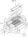
- the battery module includes: a battery stack including a plurality of batteries that are stacked, each of the plurality of batteries having a valve portion through which a gas is blown off; a duct plate configured to cover a surface of the battery stack on which a plurality of the valve portions are disposed, the duct plate having a gas discharge duct that extends in a stacking direction of the batteries, is connected to the valve portions of the respective batteries, and temporarily stores a blown-off gas; a cover plate placed on the duct plate; and a flow path portion defined by the duct plate and the cover plate, the flow path portion extending from the gas discharge duct in a first direction that intersects with the stacking direction of the batteries and allowing leaking of the gas in the gas discharge duct to an outside of the battery module.
- the cover plate has an opening through which a midst portion of the flow path portion is communicable with an outside of the battery module.
- the safety of a battery module can be enhanced.
- Duct plate 28 has openings 40 through which output terminals 22 are exposed at positions corresponding to output terminals 22 of respective batteries 14. Bus bars 42 are placed on respective openings 40. The plurality of bus bars 42 are supported by duct plate 28. Accordingly, duct plate 28 also functions as a so-called bus bar plate. Bus bar 42 placed in respective openings 40 electrically connects output terminals 22 of batteries 14 disposed adjacently to each other.
- gas discharge duct 38 can receive an impact and a pressure of a blown-off gas.
- gas discharge duct 38 can receive a large impact or a rapidly rising pressure generated at an initial stage of blowing off of a gas.
- a gas blown off to gas discharge duct 38 gradually leaks to the outside of battery module 1 through flow path portions 76. Accordingly, it is possible to prevent a gas from being vigorously blown off to the outside of battery module 1.
- a temperature of the gas or fine particles can be lowered until the gas or the fine particles reach flow path outlets 80. With such a configuration, it is possible to suppress the occurrence of fire outside battery module 1.
- an inner pressure in flow path portion 76 is reduced by forming openings 96 in cover plate 60. Accordingly, it is possible to suppress an increase in size of battery module 1 as compared with a case where an excessive increase in pressure in flow path portion 76 is suppressed by increasing a volume of flow path portion 76. In addition, since openings 96 are only formed in cover plate 60 and the number of components is not increased, it is possible to prevent the structure of battery module 1 from becoming complicated or large-sized.
- each opening 96 is set in a state where the flow path resistance of openings 96 is larger than the flow path resistance of flow path portion 76. As a result, it is possible to prevent an outflow amount of a gas from respective openings 96 from exceeding an outflow amount of the gas from the flow path outlets 80. Since the gas leaking from flow path outlet 80 remains in flow path portion 76 longer than the gas leaking from openings 96, the gas is discharged to the outside of battery module 1 in a state where the temperature is further lowered.
- FIG. 5(A) is a cross-sectional view schematically illustrating a portion of battery module 1 according to a first modification.
- the illustration of an internal structure of battery 14 and first wall portion 34 is omitted.
- first end portion 96a of opening 96 closer to a flow path portion 76 and second end portion 96b of opening 96 opposite to first end portion 96a are at least partially displaced from each other.
- a main flow of a gas in flow path portion 76 extends in horizontal direction Y from opening 78 toward flow path outlet 80. Therefore, by arranging second end portion 96b closer to gas discharge duct 38 than first end portion 96a, communication path 96c can be connected to the main flow of the gas at an acute angle. Accordingly, it is possible to more effectively prevent fine particles from being discharged from openings 96 to the outside of battery module 1.
- FIG. 5(B) is a cross-sectional view schematically illustrating a portion of battery module 1 according to a second modification.
- FIG. 5(B) illustration of the internal structure of battery 14 and first wall portion 34 is omitted.
- first end portion 96a and second end portion 96b are at least partially displaced from each other when viewed from a direction in which cover plate 60 and duct plate 28 are arranged with each other (vertical direction Z in the present modification).
- communication path 96c that connects first end portion 96a and second end portion 96b to each other is bent or curved.
- FIG. 5(B) illustrates communication path 96c bent in a crank shape as an example.
- second end portion 96b of the present modification is also disposed closer to gas discharge duct 38 than first end portion 96a in the same manner as the first modification.
- Communication path 96c extends upward from first end portion 96a and is bent at a substantially right angle toward a gas discharge duct 38 in an intermediate region in a thickness of cover plate 60. Further, communication path 96c extends in horizontal direction Y toward gas discharge duct 38, is bent toward a second end portion 96b at a substantially right angle immediately below second end portion 96b, and is connected to second end portion 96b.
- the number of batteries 14 that battery module 1 includes is not particularly limited.
- the structures of respective parts of battery module 1 including the shape of side separator 10 and the fastening structure between end plates 4 and constraining members 12 are not particularly limited.
- Battery 14 may have a cylindrical shape or the like. In a case where both heat conduction and a frictional force can be sufficiently ensured between battery stack 2 and cooling plate 6, heat conductive layer 8 may be omitted, and an insulating sheet made of PET or PC may be interposed between battery stack 2 and cooling plate 6.
- the arrangement and number of the openings 96 included in cover plate 60 can be appropriately set in consideration of a balance between an amount of gas discharged from flow path outlet 80 and an amount of gas discharged from openings 96, an amount of increase in inner pressure in flow path portion 76 and the like.
- the shape of communication path 96c in the second modification may be set in a state where a cross-sectional shape along a YZ plane perpendicular to stacking direction X may be an S shape, a lateral V shape (a shape obtained by rotating a V shape by 90°), a lateral U shape (a shape obtained by rotating a U shape by 90°) or the like.
Landscapes
- Chemical & Material Sciences (AREA)
- Chemical Kinetics & Catalysis (AREA)
- Electrochemistry (AREA)
- General Chemical & Material Sciences (AREA)
- Engineering & Computer Science (AREA)
- Manufacturing & Machinery (AREA)
- Aviation & Aerospace Engineering (AREA)
- Battery Mounting, Suspending (AREA)
- Gas Exhaust Devices For Batteries (AREA)
Claims (4)
- Batteriemodul (1), das Folgendes umfasst:einen Batteriestapel (2), der eine Vielzahl von Batterien (14) beinhaltet, die gestapelt sind, wobei die Vielzahl von Batterien (14) Ventile beinhalten, durch die ein Gas abgeblasen wird und die prismatisch sind;eine Kanalplatte (28), die dazu ausgelegt ist, eine Fläche des Batteriestapels (2) abzudecken, auf der die Ventile angeordnet sind, wobei die Kanalplatte (28) einen Gasaustrittskanal (38) beinhaltet, der sich in einer Stapelrichtung (X) der Batterien (14) erstreckt, mit den Ventilen der Batterien (14) verbunden ist und vorübergehend das Gas, das aus den Ventilen abgeblasen wird, speichert;eine Abdeckplatte (60) die auf der Kanalplatte (28) platziert ist; undeinen Strömungspfad (76), der von der Kanalplatte (28) und der Abdeckplatte (60) definiert wird, wobei sich der Strömungspfad (76) vom Gasaustrittskanal (38) in eine erste Richtung, die die Stapelrichtung der Batterien (14) schneidet, erstreckt und ein Entweichen des Gases im Gasaustrittskanal (38) zu einer Außenseite des Batteriemoduls (1) erlaubt, wobei die erste Richtung eine horizontale Richtung (Y) ist,wobei das Batteriemodul (1) ferner Strömungspfadauslässe (80) umfasst, die mit dem Strömungspfad (76) verbunden und in der horizontalen Richtung (Y) an Endabschnitten des Batteriemoduls (1) angeordnet sind,wobei die Abdeckplatte (60) eine Vielzahl von Öffnungen (96) beinhaltet, die in einem Zustand, in dem der Gasaustrittskanal (38) zwischen der Vielzahl von Öffnungen (96) eingeschlossen ist, auf beiden Seiten der Abdeckplatte (60) in der horizontalen Richtung (Y) in einem vorbestimmten Intervall in der Stapelrichtung (X) in der Abdeckplatte (60) gebildet sind, die Öffnungen (96), durch die ein mittlerer Teil des Strömungspfads (76) mit der Außenseite des Batteriemoduls (1) kommunizierbar ist, wobei ein erstes Ende (96a) der jeweiligen Öffnungen (96) in einer vertikalen Richtung (Z) mit Regionen verbunden ist, die sich jeweils zwischen einer Öffnung (78) des Strömungspfads (76) und den Strömungspfadauslässen (80) befinden, und wobei ein zweites Ende (96b) der jeweiligen Öffnung (96) in der vertikalen Richtung (Z) mit der Außenseite des Batteriemoduls (1) verbunden ist,wobei eine Größe der Öffnung (96) auf einen Zustand eingestellt ist, in dem ein Strömungspfadwiderstand in der Öffnung (96) größer ist als ein Strömungspfadwiderstand des Strömungspfads (76).
- Batteriemodul (1) nach Anspruch 1, wobei das erste Ende (96a) der Öffnung (96), das einem Strömungspfadabschnitt (76) näher ist, und das zweite Ende (96b) Ende der Öffnung (96) gegenüber dem ersten Ende (96a) mindestens teilweise voneinander versetzt sind, wie in einer Richtung gesehen, in der die Abdeckplatte (60) und die Kanalplatte (28) miteinander angeordnet sind.
- Batteriemodul (1) nach Anspruch 2, wobei das zweite Ende (96b) in der ersten Richtung näher am Gasaustrittskanal (38) angeordnet ist als das erste Ende (96a).
- Batteriemodul (1) nach einem von Anspruch 1 bis Anspruch 3, das ferner einen Kommunikationspfad (96c) umfasst, der von Innenwänden der Öffnung (96) gebildet wird:
wobei der Kommunikationspfad (96c), der das erste Ende (96a) der Öffnung (96), das dem Strömungspfad (76) näher ist, und das zweite Ende (96b) der Öffnung (96) gegenüber dem ersten Ende (96a) verbindet, gebogen oder gekrümmt ist.
Applications Claiming Priority (2)
| Application Number | Priority Date | Filing Date | Title |
|---|---|---|---|
| JP2019051229 | 2019-03-19 | ||
| PCT/JP2019/051121 WO2020188948A1 (ja) | 2019-03-19 | 2019-12-26 | 電池モジュール |
Publications (3)
| Publication Number | Publication Date |
|---|---|
| EP3944356A1 EP3944356A1 (de) | 2022-01-26 |
| EP3944356A4 EP3944356A4 (de) | 2022-05-04 |
| EP3944356B1 true EP3944356B1 (de) | 2025-07-09 |
Family
ID=72519026
Family Applications (1)
| Application Number | Title | Priority Date | Filing Date |
|---|---|---|---|
| EP19919584.3A Active EP3944356B1 (de) | 2019-03-19 | 2019-12-26 | Batteriemodul |
Country Status (5)
| Country | Link |
|---|---|
| US (1) | US12087963B2 (de) |
| EP (1) | EP3944356B1 (de) |
| JP (1) | JP7418405B2 (de) |
| CN (1) | CN113574726B (de) |
| WO (1) | WO2020188948A1 (de) |
Families Citing this family (21)
| Publication number | Priority date | Publication date | Assignee | Title |
|---|---|---|---|---|
| CN114583369A (zh) * | 2016-11-09 | 2022-06-03 | Cps 科技控股有限公司 | 电池包 |
| WO2020218222A1 (ja) * | 2019-04-24 | 2020-10-29 | 三洋電機株式会社 | 支持プレートおよび電圧検出線モジュール |
| US12355098B2 (en) | 2019-09-05 | 2025-07-08 | Samsung Sdi Co., Ltd. | Energy storage module |
| US11735795B2 (en) | 2019-09-05 | 2023-08-22 | Samsung Sdi Co., Ltd. | Energy storage module |
| US11799167B2 (en) | 2019-09-05 | 2023-10-24 | Samsung Sdi Co., Ltd. | Energy storage module having extinguisher sheet |
| US11569546B2 (en) | 2019-09-05 | 2023-01-31 | Samsung Sdi Co., Ltd. | Energy storage module |
| US11735788B2 (en) | 2019-09-05 | 2023-08-22 | Samsung Sdi Co., Ltd. | Energy storage module including insulation spacers and an extinguisher sheet |
| US11728541B2 (en) | 2019-09-05 | 2023-08-15 | Samsung Sdi Co., Ltd. | Energy storage module |
| US12090354B2 (en) | 2019-09-05 | 2024-09-17 | Samsung Sdi Co., Ltd. | Energy storage module |
| US11764438B2 (en) | 2019-09-05 | 2023-09-19 | Samsung Sdi Co., Ltd. | Energy storage module having extinguisher sheet |
| US12300848B2 (en) * | 2019-09-05 | 2025-05-13 | Samsung Sdi Co., Ltd. | Energy storage module including extinguisher sheet |
| US11848461B2 (en) | 2019-09-05 | 2023-12-19 | Samsung Sdi Co., Ltd. | Energy storage module |
| US12288895B2 (en) | 2019-09-05 | 2025-04-29 | Samsung Sdi Co., Ltd. | Energy storage module |
| US12057598B2 (en) | 2019-09-05 | 2024-08-06 | Samsung Sdi Co., Ltd. | Energy storage module including extinguisher sheet |
| US11771935B2 (en) | 2019-09-05 | 2023-10-03 | Samsung Sdi Co., Ltd. | Energy storage module |
| US11764430B2 (en) | 2019-09-05 | 2023-09-19 | Samsung Sdi Co., Ltd. | Energy storage module |
| CN116868423A (zh) * | 2021-02-25 | 2023-10-10 | 松下新能源株式会社 | 电池组 |
| JP7658669B2 (ja) * | 2021-03-18 | 2025-04-08 | エルジー エナジー ソリューション リミテッド | 電池モジュールおよびこれを含む電池パック |
| DE102021118396A1 (de) * | 2021-07-15 | 2023-01-19 | Audi Aktiengesellschaft | Modulgehäuseanordnung, Batteriemodul und Verfahren zum Verspannen eines Batteriemoduls |
| US20240055717A1 (en) * | 2022-08-15 | 2024-02-15 | GM Global Technology Operations LLC | Thermal runaway protection blanket for battery modules |
| WO2025258529A1 (ja) * | 2024-06-10 | 2025-12-18 | 株式会社Gsユアサ | 蓄電盤及び蓄電装置 |
Family Cites Families (21)
| Publication number | Priority date | Publication date | Assignee | Title |
|---|---|---|---|---|
| US4207387A (en) * | 1978-08-21 | 1980-06-10 | The Richardson Company | Container for a remotely-vented battery |
| JP3271495B2 (ja) * | 1995-10-24 | 2002-04-02 | 松下電器産業株式会社 | 組蓄電池 |
| JP5466906B2 (ja) * | 2009-09-18 | 2014-04-09 | パナソニック株式会社 | 電池モジュール |
| JP5420064B2 (ja) * | 2010-12-13 | 2014-02-19 | パナソニック株式会社 | 電池パック |
| WO2012147150A1 (ja) | 2011-04-25 | 2012-11-01 | 日立ビークルエナジー株式会社 | 組電池および単電池 |
| JP2015133169A (ja) | 2012-04-27 | 2015-07-23 | 三洋電機株式会社 | 電源装置及びこれを備える車両並びに蓄電装置 |
| WO2014024433A1 (ja) * | 2012-08-09 | 2014-02-13 | 三洋電機株式会社 | 電源装置及びこれを備える電動車両並びに蓄電装置 |
| US9627663B2 (en) * | 2013-04-25 | 2017-04-18 | Samsung Sdi Co., Ltd. | Rechargeable battery pack including pack cover |
| JP2014220148A (ja) * | 2013-05-09 | 2014-11-20 | 愛三工業株式会社 | バスバーモジュール |
| JP5737351B2 (ja) | 2013-09-05 | 2015-06-17 | 株式会社豊田自動織機 | 電池モジュール |
| JP2015135763A (ja) * | 2014-01-17 | 2015-07-27 | トヨタ自動車株式会社 | 蓄電装置 |
| JP6427941B2 (ja) * | 2014-04-30 | 2018-11-28 | 株式会社Gsユアサ | 蓄電装置 |
| WO2016026051A1 (en) * | 2014-08-22 | 2016-02-25 | Corvus Energy Ltd. | Thermal runaway containment apparatus for a battery |
| JP6274052B2 (ja) | 2014-09-04 | 2018-02-07 | 株式会社Gsユアサ | 蓄電装置 |
| KR20170069003A (ko) | 2015-12-10 | 2017-06-20 | 삼성에스디아이 주식회사 | 배터리 모듈 |
| JP6742884B2 (ja) | 2016-10-26 | 2020-08-19 | 三洋電機株式会社 | 電源装置 |
| JP6821391B2 (ja) * | 2016-10-26 | 2021-01-27 | 三洋電機株式会社 | 電源装置及びこれを用いる車両並びに蓄電装置 |
| CA3062702C (en) * | 2017-06-29 | 2023-08-15 | Sargent Manufacturing Company | Electrochemical cell housing including at least one catalyst and method of mitigating a venting and/or thermal runaway event |
| DE102017214289A1 (de) * | 2017-08-16 | 2019-02-21 | Robert Bosch Gmbh | Batteriemodul und Fahrzeug mit dem Batteriemodul |
| CN209104274U (zh) * | 2018-12-28 | 2019-07-12 | 宁德时代新能源科技股份有限公司 | 电池模组 |
| US20200266506A1 (en) * | 2019-02-18 | 2020-08-20 | 3M Innovative Properties Company | Battery module and system |
-
2019
- 2019-12-26 CN CN201980094249.4A patent/CN113574726B/zh active Active
- 2019-12-26 EP EP19919584.3A patent/EP3944356B1/de active Active
- 2019-12-26 JP JP2021506179A patent/JP7418405B2/ja active Active
- 2019-12-26 WO PCT/JP2019/051121 patent/WO2020188948A1/ja not_active Ceased
- 2019-12-26 US US17/436,679 patent/US12087963B2/en active Active
Also Published As
| Publication number | Publication date |
|---|---|
| WO2020188948A1 (ja) | 2020-09-24 |
| US20220140434A1 (en) | 2022-05-05 |
| JPWO2020188948A1 (de) | 2020-09-24 |
| US12087963B2 (en) | 2024-09-10 |
| JP7418405B2 (ja) | 2024-01-19 |
| CN113574726B (zh) | 2023-10-13 |
| EP3944356A1 (de) | 2022-01-26 |
| EP3944356A4 (de) | 2022-05-04 |
| CN113574726A (zh) | 2021-10-29 |
Similar Documents
| Publication | Publication Date | Title |
|---|---|---|
| EP3944356B1 (de) | Batteriemodul | |
| EP3944357B1 (de) | Batteriemodul | |
| EP3944359B1 (de) | Batteriemodul | |
| EP3926732B1 (de) | Batteriemodul | |
| US20220158294A1 (en) | Battery module | |
| CN113991231B (zh) | 电池组 | |
| US12456785B2 (en) | Battery module | |
| CN113169406B (zh) | 电池组件 | |
| CN104577017A (zh) | 具有熔断器单元的可再充电电池和电池模块 | |
| EP4235932A2 (de) | Batteriepack | |
| CN112703631B (zh) | 电池模块 | |
| EP4254591B1 (de) | Batterie, elektrische vorrichtung sowie verfahren und vorrichtung zur herstellung der batterie | |
| US20240006706A1 (en) | Battery module for preventing thermal runaway propagation | |
| CN120604388A (zh) | 电池模块、电池组和包括该电池组的车辆 |
Legal Events
| Date | Code | Title | Description |
|---|---|---|---|
| STAA | Information on the status of an ep patent application or granted ep patent |
Free format text: STATUS: THE INTERNATIONAL PUBLICATION HAS BEEN MADE |
|
| PUAI | Public reference made under article 153(3) epc to a published international application that has entered the european phase |
Free format text: ORIGINAL CODE: 0009012 |
|
| STAA | Information on the status of an ep patent application or granted ep patent |
Free format text: STATUS: REQUEST FOR EXAMINATION WAS MADE |
|
| 17P | Request for examination filed |
Effective date: 20211001 |
|
| AK | Designated contracting states |
Kind code of ref document: A1 Designated state(s): AL AT BE BG CH CY CZ DE DK EE ES FI FR GB GR HR HU IE IS IT LI LT LU LV MC MK MT NL NO PL PT RO RS SE SI SK SM TR |
|
| REG | Reference to a national code |
Ref country code: DE Free format text: PREVIOUS MAIN CLASS: H01M0002100000 Ipc: H01M0050209000 Ref country code: DE Ref legal event code: R079 Ref document number: 602019072477 Country of ref document: DE Free format text: PREVIOUS MAIN CLASS: H01M0002100000 Ipc: H01M0050209000 |
|
| A4 | Supplementary search report drawn up and despatched |
Effective date: 20220404 |
|
| RIC1 | Information provided on ipc code assigned before grant |
Ipc: H01M 10/6554 20140101ALI20220329BHEP Ipc: H01M 10/625 20140101ALI20220329BHEP Ipc: H01M 10/613 20140101ALI20220329BHEP Ipc: H01M 50/342 20210101ALI20220329BHEP Ipc: H01M 50/358 20210101ALI20220329BHEP Ipc: H01M 50/249 20210101ALI20220329BHEP Ipc: H01M 50/209 20210101AFI20220329BHEP |
|
| DAV | Request for validation of the european patent (deleted) | ||
| DAX | Request for extension of the european patent (deleted) | ||
| STAA | Information on the status of an ep patent application or granted ep patent |
Free format text: STATUS: EXAMINATION IS IN PROGRESS |
|
| 17Q | First examination report despatched |
Effective date: 20240916 |
|
| GRAP | Despatch of communication of intention to grant a patent |
Free format text: ORIGINAL CODE: EPIDOSNIGR1 |
|
| STAA | Information on the status of an ep patent application or granted ep patent |
Free format text: STATUS: GRANT OF PATENT IS INTENDED |
|
| RIC1 | Information provided on ipc code assigned before grant |
Ipc: H01M 10/6554 20140101ALI20250325BHEP Ipc: H01M 10/625 20140101ALI20250325BHEP Ipc: H01M 10/613 20140101ALI20250325BHEP Ipc: H01M 50/271 20210101ALI20250325BHEP Ipc: H01M 50/342 20210101ALI20250325BHEP Ipc: H01M 50/358 20210101ALI20250325BHEP Ipc: H01M 50/249 20210101ALI20250325BHEP Ipc: H01M 50/209 20210101AFI20250325BHEP |
|
| INTG | Intention to grant announced |
Effective date: 20250402 |
|
| GRAS | Grant fee paid |
Free format text: ORIGINAL CODE: EPIDOSNIGR3 |
|
| GRAA | (expected) grant |
Free format text: ORIGINAL CODE: 0009210 |
|
| STAA | Information on the status of an ep patent application or granted ep patent |
Free format text: STATUS: THE PATENT HAS BEEN GRANTED |
|
| AK | Designated contracting states |
Kind code of ref document: B1 Designated state(s): AL AT BE BG CH CY CZ DE DK EE ES FI FR GB GR HR HU IE IS IT LI LT LU LV MC MK MT NL NO PL PT RO RS SE SI SK SM TR |
|
| REG | Reference to a national code |
Ref country code: GB Ref legal event code: FG4D |
|
| REG | Reference to a national code |
Ref country code: CH Ref legal event code: EP |
|
| REG | Reference to a national code |
Ref country code: IE Ref legal event code: FG4D |
|
| REG | Reference to a national code |
Ref country code: DE Ref legal event code: R096 Ref document number: 602019072477 Country of ref document: DE |
|
| REG | Reference to a national code |
Ref country code: SE Ref legal event code: TRGR |
|
| REG | Reference to a national code |
Ref country code: NL Ref legal event code: MP Effective date: 20250709 |
|
| PG25 | Lapsed in a contracting state [announced via postgrant information from national office to epo] |
Ref country code: PT Free format text: LAPSE BECAUSE OF FAILURE TO SUBMIT A TRANSLATION OF THE DESCRIPTION OR TO PAY THE FEE WITHIN THE PRESCRIBED TIME-LIMIT Effective date: 20251110 |
|
| PG25 | Lapsed in a contracting state [announced via postgrant information from national office to epo] |
Ref country code: NL Free format text: LAPSE BECAUSE OF FAILURE TO SUBMIT A TRANSLATION OF THE DESCRIPTION OR TO PAY THE FEE WITHIN THE PRESCRIBED TIME-LIMIT Effective date: 20250709 |
|
| REG | Reference to a national code |
Ref country code: AT Ref legal event code: MK05 Ref document number: 1812760 Country of ref document: AT Kind code of ref document: T Effective date: 20250709 |
|
| PG25 | Lapsed in a contracting state [announced via postgrant information from national office to epo] |
Ref country code: IS Free format text: LAPSE BECAUSE OF FAILURE TO SUBMIT A TRANSLATION OF THE DESCRIPTION OR TO PAY THE FEE WITHIN THE PRESCRIBED TIME-LIMIT Effective date: 20251109 |
|
| PGFP | Annual fee paid to national office [announced via postgrant information from national office to epo] |
Ref country code: GB Payment date: 20251229 Year of fee payment: 7 |
|
| PGFP | Annual fee paid to national office [announced via postgrant information from national office to epo] |
Ref country code: NO Payment date: 20251216 Year of fee payment: 7 |
|
| REG | Reference to a national code |
Ref country code: LT Ref legal event code: MG9D |
|
| PG25 | Lapsed in a contracting state [announced via postgrant information from national office to epo] |
Ref country code: AT Free format text: LAPSE BECAUSE OF FAILURE TO SUBMIT A TRANSLATION OF THE DESCRIPTION OR TO PAY THE FEE WITHIN THE PRESCRIBED TIME-LIMIT Effective date: 20250709 |
|
| PG25 | Lapsed in a contracting state [announced via postgrant information from national office to epo] |
Ref country code: FI Free format text: LAPSE BECAUSE OF FAILURE TO SUBMIT A TRANSLATION OF THE DESCRIPTION OR TO PAY THE FEE WITHIN THE PRESCRIBED TIME-LIMIT Effective date: 20250709 |
|
| PG25 | Lapsed in a contracting state [announced via postgrant information from national office to epo] |
Ref country code: HR Free format text: LAPSE BECAUSE OF FAILURE TO SUBMIT A TRANSLATION OF THE DESCRIPTION OR TO PAY THE FEE WITHIN THE PRESCRIBED TIME-LIMIT Effective date: 20250709 |
|
| PGFP | Annual fee paid to national office [announced via postgrant information from national office to epo] |
Ref country code: FR Payment date: 20251222 Year of fee payment: 7 |
|
| PG25 | Lapsed in a contracting state [announced via postgrant information from national office to epo] |
Ref country code: GR Free format text: LAPSE BECAUSE OF FAILURE TO SUBMIT A TRANSLATION OF THE DESCRIPTION OR TO PAY THE FEE WITHIN THE PRESCRIBED TIME-LIMIT Effective date: 20251010 |
|
| PGFP | Annual fee paid to national office [announced via postgrant information from national office to epo] |
Ref country code: SE Payment date: 20251217 Year of fee payment: 7 |
|
| PG25 | Lapsed in a contracting state [announced via postgrant information from national office to epo] |
Ref country code: LV Free format text: LAPSE BECAUSE OF FAILURE TO SUBMIT A TRANSLATION OF THE DESCRIPTION OR TO PAY THE FEE WITHIN THE PRESCRIBED TIME-LIMIT Effective date: 20250709 |
|
| PG25 | Lapsed in a contracting state [announced via postgrant information from national office to epo] |
Ref country code: BG Free format text: LAPSE BECAUSE OF FAILURE TO SUBMIT A TRANSLATION OF THE DESCRIPTION OR TO PAY THE FEE WITHIN THE PRESCRIBED TIME-LIMIT Effective date: 20250709 Ref country code: PL Free format text: LAPSE BECAUSE OF FAILURE TO SUBMIT A TRANSLATION OF THE DESCRIPTION OR TO PAY THE FEE WITHIN THE PRESCRIBED TIME-LIMIT Effective date: 20250709 |
|
| PG25 | Lapsed in a contracting state [announced via postgrant information from national office to epo] |
Ref country code: RS Free format text: LAPSE BECAUSE OF FAILURE TO SUBMIT A TRANSLATION OF THE DESCRIPTION OR TO PAY THE FEE WITHIN THE PRESCRIBED TIME-LIMIT Effective date: 20251009 |
|
| PG25 | Lapsed in a contracting state [announced via postgrant information from national office to epo] |
Ref country code: ES Free format text: LAPSE BECAUSE OF FAILURE TO SUBMIT A TRANSLATION OF THE DESCRIPTION OR TO PAY THE FEE WITHIN THE PRESCRIBED TIME-LIMIT Effective date: 20250709 |
|
| PG25 | Lapsed in a contracting state [announced via postgrant information from national office to epo] |
Ref country code: RO Free format text: LAPSE BECAUSE OF FAILURE TO SUBMIT A TRANSLATION OF THE DESCRIPTION OR TO PAY THE FEE WITHIN THE PRESCRIBED TIME-LIMIT Effective date: 20250709 |
|
| PG25 | Lapsed in a contracting state [announced via postgrant information from national office to epo] |
Ref country code: SM Free format text: LAPSE BECAUSE OF FAILURE TO SUBMIT A TRANSLATION OF THE DESCRIPTION OR TO PAY THE FEE WITHIN THE PRESCRIBED TIME-LIMIT Effective date: 20250709 |
|
| PG25 | Lapsed in a contracting state [announced via postgrant information from national office to epo] |
Ref country code: DK Free format text: LAPSE BECAUSE OF FAILURE TO SUBMIT A TRANSLATION OF THE DESCRIPTION OR TO PAY THE FEE WITHIN THE PRESCRIBED TIME-LIMIT Effective date: 20250709 |
|
| PGFP | Annual fee paid to national office [announced via postgrant information from national office to epo] |
Ref country code: DE Payment date: 20251222 Year of fee payment: 7 |
|
| PG25 | Lapsed in a contracting state [announced via postgrant information from national office to epo] |
Ref country code: IT Free format text: LAPSE BECAUSE OF FAILURE TO SUBMIT A TRANSLATION OF THE DESCRIPTION OR TO PAY THE FEE WITHIN THE PRESCRIBED TIME-LIMIT Effective date: 20250709 |