US11764438B2 - Energy storage module having extinguisher sheet - Google Patents
Energy storage module having extinguisher sheet Download PDFInfo
- Publication number
- US11764438B2 US11764438B2 US17/014,034 US202017014034A US11764438B2 US 11764438 B2 US11764438 B2 US 11764438B2 US 202017014034 A US202017014034 A US 202017014034A US 11764438 B2 US11764438 B2 US 11764438B2
- Authority
- US
- United States
- Prior art keywords
- energy storage
- storage module
- battery cells
- extinguisher
- positive electrode
- Prior art date
- Legal status (The legal status is an assumption and is not a legal conclusion. Google has not performed a legal analysis and makes no representation as to the accuracy of the status listed.)
- Active
Links
Images


Classifications
-
- H—ELECTRICITY
- H01—ELECTRIC ELEMENTS
- H01M—PROCESSES OR MEANS, e.g. BATTERIES, FOR THE DIRECT CONVERSION OF CHEMICAL ENERGY INTO ELECTRICAL ENERGY
- H01M10/00—Secondary cells; Manufacture thereof
- H01M10/60—Heating or cooling; Temperature control
- H01M10/61—Types of temperature control
- H01M10/613—Cooling or keeping cold
-
- H—ELECTRICITY
- H01—ELECTRIC ELEMENTS
- H01M—PROCESSES OR MEANS, e.g. BATTERIES, FOR THE DIRECT CONVERSION OF CHEMICAL ENERGY INTO ELECTRICAL ENERGY
- H01M50/00—Constructional details or processes of manufacture of the non-active parts of electrochemical cells other than fuel cells, e.g. hybrid cells
- H01M50/30—Arrangements for facilitating escape of gases
- H01M50/383—Flame arresting or ignition-preventing means
-
- H—ELECTRICITY
- H01—ELECTRIC ELEMENTS
- H01M—PROCESSES OR MEANS, e.g. BATTERIES, FOR THE DIRECT CONVERSION OF CHEMICAL ENERGY INTO ELECTRICAL ENERGY
- H01M10/00—Secondary cells; Manufacture thereof
- H01M10/60—Heating or cooling; Temperature control
- H01M10/64—Heating or cooling; Temperature control characterised by the shape of the cells
- H01M10/647—Prismatic or flat cells, e.g. pouch cells
-
- H—ELECTRICITY
- H01—ELECTRIC ELEMENTS
- H01M—PROCESSES OR MEANS, e.g. BATTERIES, FOR THE DIRECT CONVERSION OF CHEMICAL ENERGY INTO ELECTRICAL ENERGY
- H01M10/00—Secondary cells; Manufacture thereof
- H01M10/60—Heating or cooling; Temperature control
- H01M10/65—Means for temperature control structurally associated with the cells
- H01M10/658—Means for temperature control structurally associated with the cells by thermal insulation or shielding
-
- H—ELECTRICITY
- H01—ELECTRIC ELEMENTS
- H01M—PROCESSES OR MEANS, e.g. BATTERIES, FOR THE DIRECT CONVERSION OF CHEMICAL ENERGY INTO ELECTRICAL ENERGY
- H01M4/00—Electrodes
- H01M4/02—Electrodes composed of, or comprising, active material
- H01M4/36—Selection of substances as active materials, active masses, active liquids
- H01M4/48—Selection of substances as active materials, active masses, active liquids of inorganic oxides or hydroxides
- H01M4/52—Selection of substances as active materials, active masses, active liquids of inorganic oxides or hydroxides of nickel, cobalt or iron
- H01M4/523—Selection of substances as active materials, active masses, active liquids of inorganic oxides or hydroxides of nickel, cobalt or iron for non-aqueous cells
-
- H—ELECTRICITY
- H01—ELECTRIC ELEMENTS
- H01M—PROCESSES OR MEANS, e.g. BATTERIES, FOR THE DIRECT CONVERSION OF CHEMICAL ENERGY INTO ELECTRICAL ENERGY
- H01M4/00—Electrodes
- H01M4/02—Electrodes composed of, or comprising, active material
- H01M4/36—Selection of substances as active materials, active masses, active liquids
- H01M4/58—Selection of substances as active materials, active masses, active liquids of inorganic compounds other than oxides or hydroxides, e.g. sulfides, selenides, tellurides, halogenides or LiCoFy; of polyanionic structures, e.g. phosphates, silicates or borates
- H01M4/5825—Oxygenated metallic salts or polyanionic structures, e.g. borates, phosphates, silicates, olivines
-
- H—ELECTRICITY
- H01—ELECTRIC ELEMENTS
- H01M—PROCESSES OR MEANS, e.g. BATTERIES, FOR THE DIRECT CONVERSION OF CHEMICAL ENERGY INTO ELECTRICAL ENERGY
- H01M50/00—Constructional details or processes of manufacture of the non-active parts of electrochemical cells other than fuel cells, e.g. hybrid cells
- H01M50/10—Primary casings, jackets or wrappings of a single cell or a single battery
- H01M50/147—Lids or covers
-
- H—ELECTRICITY
- H01—ELECTRIC ELEMENTS
- H01M—PROCESSES OR MEANS, e.g. BATTERIES, FOR THE DIRECT CONVERSION OF CHEMICAL ENERGY INTO ELECTRICAL ENERGY
- H01M50/00—Constructional details or processes of manufacture of the non-active parts of electrochemical cells other than fuel cells, e.g. hybrid cells
- H01M50/20—Mountings; Secondary casings or frames; Racks, modules or packs; Suspension devices; Shock absorbers; Transport or carrying devices; Holders
- H01M50/204—Racks, modules or packs for multiple batteries or multiple cells
- H01M50/207—Racks, modules or packs for multiple batteries or multiple cells characterised by their shape
- H01M50/209—Racks, modules or packs for multiple batteries or multiple cells characterised by their shape adapted for prismatic or rectangular cells
-
- H—ELECTRICITY
- H01—ELECTRIC ELEMENTS
- H01M—PROCESSES OR MEANS, e.g. BATTERIES, FOR THE DIRECT CONVERSION OF CHEMICAL ENERGY INTO ELECTRICAL ENERGY
- H01M50/00—Constructional details or processes of manufacture of the non-active parts of electrochemical cells other than fuel cells, e.g. hybrid cells
- H01M50/20—Mountings; Secondary casings or frames; Racks, modules or packs; Suspension devices; Shock absorbers; Transport or carrying devices; Holders
- H01M50/233—Mountings; Secondary casings or frames; Racks, modules or packs; Suspension devices; Shock absorbers; Transport or carrying devices; Holders characterised by physical properties of casings or racks, e.g. dimensions
- H01M50/24—Mountings; Secondary casings or frames; Racks, modules or packs; Suspension devices; Shock absorbers; Transport or carrying devices; Holders characterised by physical properties of casings or racks, e.g. dimensions adapted for protecting batteries from their environment, e.g. from corrosion
-
- H—ELECTRICITY
- H01—ELECTRIC ELEMENTS
- H01M—PROCESSES OR MEANS, e.g. BATTERIES, FOR THE DIRECT CONVERSION OF CHEMICAL ENERGY INTO ELECTRICAL ENERGY
- H01M50/00—Constructional details or processes of manufacture of the non-active parts of electrochemical cells other than fuel cells, e.g. hybrid cells
- H01M50/20—Mountings; Secondary casings or frames; Racks, modules or packs; Suspension devices; Shock absorbers; Transport or carrying devices; Holders
- H01M50/271—Lids or covers for the racks or secondary casings
-
- H—ELECTRICITY
- H01—ELECTRIC ELEMENTS
- H01M—PROCESSES OR MEANS, e.g. BATTERIES, FOR THE DIRECT CONVERSION OF CHEMICAL ENERGY INTO ELECTRICAL ENERGY
- H01M50/00—Constructional details or processes of manufacture of the non-active parts of electrochemical cells other than fuel cells, e.g. hybrid cells
- H01M50/30—Arrangements for facilitating escape of gases
- H01M50/35—Gas exhaust passages comprising elongated, tortuous or labyrinth-shaped exhaust passages
- H01M50/358—External gas exhaust passages located on the battery cover or case
-
- H—ELECTRICITY
- H01—ELECTRIC ELEMENTS
- H01M—PROCESSES OR MEANS, e.g. BATTERIES, FOR THE DIRECT CONVERSION OF CHEMICAL ENERGY INTO ELECTRICAL ENERGY
- H01M50/00—Constructional details or processes of manufacture of the non-active parts of electrochemical cells other than fuel cells, e.g. hybrid cells
- H01M50/30—Arrangements for facilitating escape of gases
- H01M50/375—Vent means sensitive to or responsive to temperature
-
- H—ELECTRICITY
- H01—ELECTRIC ELEMENTS
- H01M—PROCESSES OR MEANS, e.g. BATTERIES, FOR THE DIRECT CONVERSION OF CHEMICAL ENERGY INTO ELECTRICAL ENERGY
- H01M50/00—Constructional details or processes of manufacture of the non-active parts of electrochemical cells other than fuel cells, e.g. hybrid cells
- H01M50/30—Arrangements for facilitating escape of gases
- H01M50/394—Gas-pervious parts or elements
-
- H—ELECTRICITY
- H01—ELECTRIC ELEMENTS
- H01M—PROCESSES OR MEANS, e.g. BATTERIES, FOR THE DIRECT CONVERSION OF CHEMICAL ENERGY INTO ELECTRICAL ENERGY
- H01M50/00—Constructional details or processes of manufacture of the non-active parts of electrochemical cells other than fuel cells, e.g. hybrid cells
- H01M50/40—Separators; Membranes; Diaphragms; Spacing elements inside cells
-
- H—ELECTRICITY
- H01—ELECTRIC ELEMENTS
- H01M—PROCESSES OR MEANS, e.g. BATTERIES, FOR THE DIRECT CONVERSION OF CHEMICAL ENERGY INTO ELECTRICAL ENERGY
- H01M2300/00—Electrolytes
- H01M2300/0017—Non-aqueous electrolytes
- H01M2300/0025—Organic electrolyte
-
- Y—GENERAL TAGGING OF NEW TECHNOLOGICAL DEVELOPMENTS; GENERAL TAGGING OF CROSS-SECTIONAL TECHNOLOGIES SPANNING OVER SEVERAL SECTIONS OF THE IPC; TECHNICAL SUBJECTS COVERED BY FORMER USPC CROSS-REFERENCE ART COLLECTIONS [XRACs] AND DIGESTS
- Y02—TECHNOLOGIES OR APPLICATIONS FOR MITIGATION OR ADAPTATION AGAINST CLIMATE CHANGE
- Y02E—REDUCTION OF GREENHOUSE GAS [GHG] EMISSIONS, RELATED TO ENERGY GENERATION, TRANSMISSION OR DISTRIBUTION
- Y02E60/00—Enabling technologies; Technologies with a potential or indirect contribution to GHG emissions mitigation
- Y02E60/10—Energy storage using batteries
Definitions
- aspects of embodiments of the present disclosure relate to an energy storage module.
- An energy storage module may be configured to be linked to a renewal energy and/or power system, such as, for example, a solar cell, to store electric power when demand for electric power from a load is low and to use (e.g., to discharge or provide) the stored electric power when demand for electric power is high.
- the energy storage module generally includes (or is) an apparatus including a relatively large quantity of battery cells (e.g., secondary batteries or secondary battery cells).
- the energy storage module generally exhibits high-capacity and high-output characteristics, and research into technology to increase the safety of energy storage modules is being actively conducted.
- the battery cells are generally received in (or placed on or fixed to) multiple trays, which are received (or accommodated) in a rack, and multiple racks are received (or accommodated) in a container box.
- Embodiments of the present disclosure are related to an energy storage module exhibiting a reduced fire risk and exhibiting increased safety by reducing or minimizing the chance of a fire spreading between adjacent battery cells when a fire occurs.
- an energy storage module includes: a cover member accommodating a plurality of battery cells in an internal receiving space, the battery cells being arranged in a first direction, each of the battery cells including a vent; a top plate coupled to a top of the cover member and including a duct corresponding to the vent of each of the battery cells; a top cover coupled to a top of the top plate and having a discharge opening corresponding to the duct; and an extinguisher sheet between the top cover and the top plate, the extinguisher sheet being configured to emit a fire extinguishing agent at a reference temperature.
- the extinguisher sheet may have an opening corresponding to the duct.
- the extinguisher sheet may extend in the first direction.
- the energy storage module may further include a plurality of insulation spacers respectively between adjacent ones of the battery cells.
- the top plate may have openings respectively corresponding to the insulation spacers.
- the extinguisher sheet may be over the openings in the top plate and over the insulation spacers.
- the extinguisher sheet may have a receiving space with an outer cover comprising polyurea or polyurethane and a fire extinguishing agent in the receiving space.
- the receiving space may be a capsule or tube.
- the fire extinguishing agent may include halogenated carbon.
- the extinguisher sheet may include a plurality of sheets respectively configured to emit the fire extinguishing agent at different temperatures.
- the sheets of the extinguisher sheet may be stacked on each other.
- the energy storage module may further include a plurality of the extinguisher sheets.
- Each of the extinguisher sheets may extend in the first direction.
- a first one of the extinguisher sheets may be between a first electrode terminal of one of the battery cells and the vent of the one of the battery cells, and a second one of the extinguisher sheets may be between a second electrode terminal of the one of the battery cells and the vent of the one of the battery cells.
- the extinguisher sheets may be spaced from the battery cells by a first distance, and an upper end of the duct may be spaced from the battery cells by a second distance, the first distance being greater than the second distance.
- a proportion of the fire extinguishing agent contained in the extinguisher sheet to the total weight of the extinguisher sheet may be in a range from 30% to 50%.
- the fire extinguishing agent may be contained in the extinguisher sheet in an amount of 0.12 g/cm 3 to 0.82 g/cm 3 .
- Each of the battery cells may include: a negative electrode including: a negative electrode current collector; a negative electrode active material layer on the negative electrode current collector; and a negative electrode function layer on the negative electrode active material layer; and a positive electrode including: a positive electrode current collector; and a positive electrode active material layer on the positive electrode current collector.
- the negative electrode function layer may include flake-shaped polyethylene particles
- the positive electrode active material layer may include a first positive electrode active material including at least one composite oxide of lithium and a metal selected from the group consisting of cobalt (Co), manganese (Mn), nickel (Ni), and a combination of these metals, and a second positive electrode active material including a compound represented by the Chemical Formula (1): Li a Fe 1-x M x PO 4 (1) wherein 0.90 ⁇ a ⁇ 1.8, 0 ⁇ x ⁇ 0.7, and M is Mn, Co, Ni, or a combination thereof.
- the flake-shaped polyethylene particles may have an average particle diameter (D50) in a range from 1 ⁇ m to 8 ⁇ m.
- the flake-shaped polyethylene particles may have an average particle diameter (D50) in a range from 2 ⁇ m to 6 ⁇ m.
- the flake-shaped polyethylene particles may have a thickness in a range from 0.2 ⁇ m to 4 ⁇ m.
- the first positive electrode active material and the second positive electrode active material may be contained in a weight ratio in a range from 97:3 to 80:20.
- the energy storage module according to embodiments of the present disclosure suppresses ignition by providing battery cells having a shut-down function by using compositions of negative and positive electrode active materials. Further, energy storage modules according to embodiments of the present disclosure can prevent or reduce heat from spreading to adjacent battery cells by rapidly extinguishing a fire therein and cooling the battery cell(s) when a vent of the battery cell(s) opens (or ruptures) and/or when a fire occurs.
- FIG. 1 is a perspective view of an energy storage module according to an embodiment of the present disclosure.
- FIG. 2 is a partially enlarged view of the portion A of FIG. 1 .
- FIG. 3 is an exploded perspective view of the energy storage module shown in FIGS. 1 and 2 .
- FIG. 4 is an exploded perspective bottom view of an extinguisher sheet and a top cover of the energy storage module shown in FIGS. 1 - 3 .
- FIG. 5 A shows a plurality of energy storage modules coupled to a rack according to an embodiment of the present disclosure.
- FIGS. 5 B and 5 C illustrate gas movement from a battery cell through a duct in the energy storage module shown in FIGS. 1 - 4 .
- FIG. 6 is a perspective view of the extinguisher sheet coupled to a top plate of the energy storage module shown in FIGS. 1 - 4 .
- FIG. 7 is a partially enlarged view of the portion B of FIG. 6 .
- FIGS. 8 A and 8 B illustrate the extinguisher sheet in the energy storage module according to an embodiment of the present disclosure.
- FIGS. 9 A- 9 D are cross-sectional views of extinguisher sheets according to embodiments of the present disclosure.
- FIG. 10 is a perspective view of battery cells and insulation spacers arranged on a bottom plate of the energy storage module according to an embodiment of the present disclosure.
- FIG. 11 is a cross-sectional view taken along the line 11 - 11 of FIG. 1 .
- FIG. 12 is a perspective view illustrating one of the insulation spacers in the energy storage module according to an embodiment of the present disclosure.
- FIG. 13 is a partially enlarged view of the portion C of FIG. 11 .
- FIG. 14 is a perspective view of an energy storage module according to another embodiment of the present disclosure.
- FIG. 15 is a plan view illustrating an extinguisher sheet that is coupled to a top plate in the energy storage module shown in FIG. 14 .
- FIG. 16 is a cross-sectional view of a part of the energy storage module shown in FIGS. 14 and 15 .
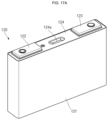
- FIGS. 17 A and 17 B are a perspective view and a cross-sectional view, respectively, of a battery cell of an energy storage module according to an embodiment of the present disclosure.
- FIG. 18 is a scanning electron microscope (SEM) image of polyethylene spherical particles in an aqueous dispersion.
- FIG. 19 is a SEM image of flake-shaped polyethylene particles according to an embodiment of the present disclosure.
- FIG. 20 is a SEM image of an electrode composition according to an embodiment of the present disclosure.
- FIG. 21 is a graph showing particle size distribution analysis results of flake-shaped polyethylene particles contained in electrode compositions prepared according to Examples 1 to 3.
- FIG. 22 is a graph showing ACR increase rate evaluation results of electrode plates depending on temperatures.
- FIG. 23 is a graph showing capacity retention evaluation results of lithium secondary batteries according to Examples for 150 cycles.
- FIG. 24 is a diagram showing a symmetrical coin-type cell fabricated for evaluating resistance increase rates of an electrode plate.
- FIG. 25 is a SEM image showing a cross section of a surface of a negative electrode when a lithium secondary battery not including a positive electrode according to Example is shut down.
- FIG. 26 is a SEM image showing a surface of a negative electrode cross section when a lithium secondary battery including both of a negative electrode with a negative electrode function layer and a positive electrode is shut down.
- a first member, a first element, a first region, a first layer, and/or a first section discussed below could be termed a second member, a second element, a second region, a second layer, and/or a second section without departing from the scope of the present disclosure.
- spatially relative terms such as “beneath,” “below,” “lower,” “above,” “upper,” and the like, may be used herein for ease of description to describe one element or feature's relationship to another element(s) or feature(s) as illustrated in the figures. It will be understood that the spatially relative terms are intended to encompass different orientations of the device in use or operation, in addition to the orientation depicted in the figures. For example, if the device in the figures is turned over, elements described as “below” or “beneath” other elements or features would then be oriented “over” or “above” the other elements or features. Thus, the term “below” can encompass both an orientation of above and below.
- FIG. 1 is a perspective view of an energy storage module according to an embodiment of the present disclosure
- FIG. 2 is a partially enlarged view of the portion A of FIG. 1
- FIG. 3 is an exploded perspective view of the energy storage module shown in FIGS. 1 and 2
- FIG. 4 is an exploded perspective bottom view of a bottom surface of an extinguisher sheet and of a top cover of the energy storage module shown in FIGS. 1 - 3 .
- an energy storage module 100 includes a cover member 110 , a top plate (e.g., an upper plate) 140 , an extinguisher sheet 150 , and a top cover (e.g., an upper cover) 160 .
- the cover member 110 provides an internal space for receiving (or accommodating) battery cells and insulation spacers.
- the cover member 110 includes a bottom plate 111 , an end plate (or a plurality of end plates) 112 , and a side plate (or a plurality of side plates) 113 which provide a space in which the battery cells and the insulation spacers are arranged, which will be further described below.
- the cover member 110 may fix positions of the battery cells and the insulation spacers and may protect the battery cells from external impacts.
- the top plate 140 is coupled to a top portion (e.g., a top or a top surface) of the cover member 110 .
- the top plate 140 may be coupled to the cover member 110 while covering top portions (e.g., top surfaces) of the battery cells.
- positive electrode terminals and negative electrode terminals of the battery cells are exposed to a top portion of (e.g., are exposed through) the top plate 140 (e.g., are exposed to a top portion of the top plate 140 ), and bus bars 145 are coupled to the terminals of adjacent ones of the battery cells, thereby connecting (e.g., electrically connecting) the battery cells to one another in series, in parallel, or in series/parallel.
- the top plate 140 includes a duct (e.g., a plurality of ducts) 141 corresponding to a vent located on a top surface (e.g., in a cap plate or cap assembly) of each of the battery cells. Accordingly, the gas discharged through the vent of the battery cell may move upwardly along (or through) the duct 141 of the top plate 140 .
- a duct e.g., a plurality of ducts
- the configuration and operation of the ducts 141 will be described in more detail below.
- the extinguisher sheet 150 is positioned between the top plate 140 and the top cover 160 .
- the extinguisher sheet 150 may be one or more members (or sheets) extending in one direction, for example, in a length direction, of the top plate 140 .
- the extinguisher sheet 150 may include an opening (e.g., an opening hole or a plurality of openings or openings holes) positioned to correspond to the duct 141 of the top plate 140 . Accordingly, the extinguisher sheet 150 may be positioned such that the openings therein correspond to the ducts 141 of the top plate 140 .
- the extinguisher sheet 150 may be coupled to a bottom surface of the top cover 160 . When the extinguisher sheet 150 is coupled to the bottom surface of the top cover 160 , the extinguisher sheet 150 is positioned above the top plate 140 .
- the configuration and operation of the extinguisher sheet 150 will be described in more detail below.
- the top cover 160 is coupled to the top portion (e.g., the top surface) of the top plate 140 .
- the top cover 160 may cover the top plate 140 and the bus bars 145 .
- the top cover 160 also covers the extinguisher sheet 150 coupled to its bottom surface 160 b , thereby protecting the top plate 140 , the bus bars 145 , and the extinguisher sheet 150 from external impacts applied to a top surface 160 a of the top cover 160 .
- the top cover 160 includes discharge openings (e.g., discharge holes) 161 (see, e.g., FIG. 4 ).
- the discharge openings 161 may be arranged in (e.g., adjacent each other in) one direction, for example, in a length direction, of the top cover 160 .
- the discharge openings 161 may be positioned to correspond to the ducts 141 of the top plate 140 , and each of the discharge openings 161 may include (or may be) a plurality of separate openings (e.g., sub-discharge openings) spaced apart from one another.
- the gas discharged from the vent of the battery cell may be discharged outside of the energy storage module 100 along the duct 141 of the top plate 140 and through the discharge opening 161 of the top cover 160 , thereby facilitating user safety by preventing the user's hand from contacting the internal structure of the top cover 160 .
- the top cover 160 may further include a protrusion (e.g., a protrusion part) 162 around the discharge opening 161 (e.g., around each of the discharge openings 161 ).
- the protrusion 162 may protrude from the bottom surface 160 b of the top cover 160 to be coupled to (e.g., to extend around) the exterior side (or exterior surface) of the duct 141 .
- the protrusion 162 may have a shape that corresponds to the cross-sectional shape of the duct 141 .
- FIG. 5 A shows energy storage modules that are coupled to a rack according to an embodiment of the present disclosure
- FIGS. 5 B and 5 C illustrate gas movement from a vent of a battery cell through one of the ducts 141 in the energy storage module 100 according to an embodiment of the present disclosure
- FIG. 5 B is a cross-sectional view of the energy storage module 100 along a first direction
- FIG. 5 C is a cross-sectional view thereof along a second direction perpendicular to the first direction.
- a plurality of energy storage modules 100 may be combined with (e.g., coupled to) a rack 10 .
- the number of energy storage modules 100 may vary according to the desired capacity, and the energy storage modules 100 may be mounted in the rack 10 and then be fixed thereto.
- the rack 10 may include a frame 11 defining its overall external shape and shelves 12 located at different layers (or levels) in the frame 11 .
- the shelves 12 may support bottom portions (or bottom surfaces) of the energy storage modules 100 (e.g., the energy storage modules 100 may be placed on or mounted on the shelves 12 ).
- two shelves 12 are shown in the frame 11
- two energy storage modules 100 are shown mounted on the respective shelves 12 .
- the present disclosure is not limited to the number of shelves 12 and energy storage modules 100 in the illustrated embodiment.
- the ducts 141 of the top plate 140 are located to correspond to the vents of the battery cells.
- the gas discharged from the vent may move upwardly along (or through) the duct 141 , as indicated by the arrows.
- the top plate 140 may face toward (e.g., the duct 141 may extend toward) the discharge opening 161 of the top cover 160 positioned above the duct 141 .
- the shelf 12 of the rack 10 is positioned above the top surface 160 a of the top cover 160 so the gas is between (e.g., enter the space between) the top surface 160 a of the top cover 160 and the adjacent shelf 12 .
- a distance between the top surface 160 a of the top cover 160 and the shelf 12 may be in a range from about 3 mm to about 7 mm.
- the distance is greater than or equal to about 3 mm, the heat generated by the energy storage module 100 can be easily discharged to the exterior and, when the distance is less than about 7 mm, a high-temperature inert gas atmosphere can be easily created therein, which will be described in more detail below.
- a phase change may begin to occur in a fire extinguishing agent in the extinguisher sheet 150 at a temperature in a range from about 40° C. to about 60° C., and in some embodiments, a temperature in a range from 45° C. to 55° C.
- the fire extinguishing agent may remain inside the extinguisher sheet 150 instead of being sprayed (released) therefrom.
- the amount of gas discharged through the vent gradually increases and a temperature around the vent rises and reaches a temperature in a range from about 120° C. to about 200° C., for example, a temperature in a range from about 130° C.
- a temperature in a range from 140° C. to 180° C. a gas containing an electrolytic steam may be generated mainly through the vent.
- the gas in the above temperature range may not melt a heat-resistant plastic constituting an upper plate 140 and an upper cover 160 (e.g., may allow the resistant plastic to remain unmelted), spraying of some of the fire extinguishing agent may begin. But if a separator in an electrode assembly of the battery cell melts due to a rise in the internal temperature of the battery cell, the high-temperature inert gas may be generated along with flames.
- the inert gas may fill spaces between the top surface 160 a of the top cover 160 and the adjacent shelf 12 to create an inert gas atmosphere. Accordingly, oxygen induction can be prevented and the flames generated by the battery cell can be blocked (or extinguished).
- the extinguisher sheet 150 positioned under the top cover 160 may operate (e.g., may emit a fire extinguishing agent) due to the high-temperature inert gas, thereby allowing the fire extinguishing agent to be sprayed (or emitted), which will be described later in more detail.
- FIG. 6 is a perspective view of an energy storage module according to an embodiment of the present disclosure in which the extinguisher sheet is coupled to the top plate
- FIG. 7 is a partially enlarged view of the portion B of FIG. 6
- FIGS. 8 A and 8 B are cross-sectional views of the energy storage module according to an embodiment of the present disclosure
- FIGS. 9 A- 9 D are cross-sectional views of example configurations of the extinguisher sheet according to embodiments of the present disclosure.
- the extinguisher sheet 150 may be positioned between the top plate 140 and the top cover 160 , as described above. As shown in FIG. 6 , the extinguisher sheet 150 may have openings (e.g., opening holes) 151 corresponding to the ducts 141 of the top plate 140 . Accordingly, movement of the gas through the ducts 141 may not be influenced by the extinguisher sheet 150 (e.g., the extinguisher sheet 150 may not impede the movement of the gas from the battery cells).
- openings e.g., opening holes
- the extinguisher sheet 150 may operate (e.g., may emit a fire extinguishing agent) in response to heat when the inert gas having a relatively high temperature of, for example, about 200° C., is generated.
- the fire extinguishing agent contained in the extinguisher sheet 150 is sprayed (or emitted) from the extinguisher sheet 150 due to (or in response to) the high-temperature gas.
- the fire extinguishing agent may be sprayed toward (e.g., emitted or directed toward) the top plate 140 and the battery cells with directionality.
- the fire extinguishing agent may reach the underlying insulation spacers through openings (e.g., opening holes) 143 located at front and rear sides of the ducts 141 (e.g., located between the ducts 141 ) of the top plate 140 .
- a fluid guide protrusion 142 may be provided around the opening 143 (e.g., around each of the openings) of top plate 140 , thereby more efficiently guiding movement of the fire extinguishing agent.
- the fire extinguishing agent may move along surfaces of the insulation spacers, thereby extinguishing the adjacent battery cell(s) and cooling the battery cell(s).
- the extinguisher sheet 150 may be configured as shown in FIGS. 9 A- 9 D .
- the extinguisher sheet 150 may include a receiving space (or a plurality of receiving spaces) 152 containing a fire extinguishing agent within an outer cover including (or made of) polyurea or polyurethane.
- the receiving space 152 may include a micro-sized fire extinguishing capsule(s) covering (or encapsulating) the fire extinguishing agent therein.
- the fire extinguishing agent may include, for example, halogenated carbon (e.g., a halogen containing hydrocarbon compound, such as a compound consisting only of carbon and halogen atoms), such as a halogenated ketone (e.g., NOVECe, a registered trademark of 3M Corporation, St. Paul, Minn.).
- the fire extinguishing capsule(s) defining the receiving space 152 may be configured to open (or burst) to spray the fire extinguishing agent when the gas having passed through the duct 141 reaches a relatively high temperature of about 200° C.
- a high temperature atmosphere of, for example, about 200° C. the fire extinguishing capsule(s) opens (or bursts) due to increased internal pressure due to the phase change, causing the internal fire extinguishing agent to be sprayed.
- the fire extinguishing capsule may also melt at a temperature of about 200° C., thereby allowing the internal fire extinguishing agent to be sprayed (or emitted).
- a proportion of the fire extinguishing agent contained in the extinguisher sheet 150 to the overall weight of the extinguisher sheet 150 may be in a range from about 30% to about 50%.
- the proportion of the fire extinguishing agent is greater than or equal to about 30%, the battery cell(s) can be appropriately extinguished by the extinguisher sheet 150 and, when the proportion of the fire extinguishing agent is less than or equal to about 50%, the extinguisher sheet 150 can be easily set (or configured) to operate at a temperature of about 200° C.
- the fire extinguishing agent may be contained in the extinguisher sheet 150 in an amount between about 0.12 g/cm 3 to about 0.82 g/cm 3 .
- the extinguisher sheet 150 can appropriately extinguish the battery cell(s) by considering the capacity of the battery cell(s) used in the energy storage module 100 including the extinguisher sheet 150 and, when the amount of the fire extinguishing agent is less than or equal to about 0.82 g/cm 3 , the extinguisher sheet 150 can be easily set (or configured) to operate at a temperature of about 200° C.
- another example extinguisher sheet 150 A may include an internal tube-type (e.g., cylindrical) receiving space 152 A, which receives (or accommodates or stores) a fire extinguishing agent within the extinguisher sheet 150 A.
- an internal tube-type e.g., cylindrical
- another example extinguisher sheet 150 B may include receiving spaces 152 B arranged therein and spaced apart from one another (e.g., spaced apart from each other at a regular interval).
- the extinguisher sheet 150 B includes a plurality of receiving spaces 152 B that are spaced apart from one another, different from the tube-type receiving space 152 A in the extinguisher sheet 150 A described above.
- the receiving spaces 152 B of the extinguisher sheet 150 B may operate (e.g., may emit or spray the fire extinguishing agent) in response to high-temperature internal gas from the battery cells.
- the extinguisher sheet 150 B may emit (or spray) the fire extinguishing agent from the receiving spaces 152 B corresponding to (e.g., arranged over or near) the battery cells that vent the high-temperature gas.
- another example extinguisher sheet 150 C may have a multi-layer structure including a plurality of layers (or sheets).
- the extinguisher sheet 150 C may include a first extinguisher sheet 150 having lower capsule-type receiving spaces 152 and a second extinguisher sheet 150 A having an upper tube-type receiving space 152 A.
- the first extinguisher sheet 150 and the second extinguisher sheet 150 A may have different operating temperatures, thereby allowing the first extinguisher sheet 150 and the second extinguisher sheet 150 A to sequentially operate according to the temperature and amount of the vented gas.
- the extinguisher sheet 150 C may sequentially operate according to the temperature and generation time (e.g., the continued generation) of gas, thereby constantly (e.g., constantly over a period of time) spraying the fire extinguishing agent.
- the temperature and generation time e.g., the continued generation
- the extinguisher sheet 150 C may sequentially operate according to the temperature and generation time (e.g., the continued generation) of gas, thereby constantly (e.g., constantly over a period of time) spraying the fire extinguishing agent.
- FIG. 10 illustrates battery cells 120 and insulation spacers 130 arranged on the bottom plate 111 of the energy storage module 100 according to an embodiment of the present disclosure.
- FIG. 11 is a cross-sectional view taken along the line 11 - 11 ′ of FIG. 1 .
- FIG. 12 is a perspective view of one of the insulation spacers 130 according to an embodiment of the present disclosure.
- FIG. 13 is a partially enlarged view of the portion C of FIG. 11 .
- the battery cells 120 and insulation spacers 130 may be alternately arranged on a top surface of the bottom plate 111 of the cover member 110 .
- the battery cells 120 may be arranged in two columns along the top surface of the bottom plate 111 , and one of the insulation spacers 130 may be positioned between each of (e.g., between adjacent ones of) the battery cells 120 .
- Each of the battery cells 120 may include an electrode assembly accommodated within a case 121 , and the electrode assembly may be wound, stacked, or laminated in a state in which a separator is positioned between a positive electrode plate and a negative electrode plate.
- Each of the positive and negative electrode plates include an active material coated on a region (e.g., a coated portion or coated region).
- the battery cells 120 may further include electrode terminals 122 and 123 , which are electrically connected to regions of the positive and negative electrode plates that are not coated with the active material (e.g., uncoated portions or uncoated regions).
- the electrode terminals 122 and 123 may be exposed to (e.g., may extend through or above) an upper portion of the case 121 .
- the electrode terminals 122 and 123 may be referred to as a first electrode terminal 122 and a second electrode terminal 123 , respectively defining, for example, a negative electrode terminal and a positive electrode terminal, but the polarities of the electrode terminals 122 and 123 may be reversed. Occurrences of battery cell ignition can be reduced according to the compositions of the active materials of the battery cells 120 , thereby increasing safety of the battery cells 120 .
- the active material compositions will be described in more detail below.
- the insulation spacers 130 positioned between each of the battery cells 120 may prevent the battery cells 120 from contacting each other.
- the insulation spacers 130 may maintain distance (e.g., may maintain a space) between each of the battery cells 120 to establish passages for external air, thereby cooling the battery cells 120 .
- each of the insulation spacers 130 may include a sheet (e.g., a sheet part) 131 and an edge (e.g., an edge part) 132 .
- the sheet 131 may be (may include or employ) a mixture of a flame-retardant (e.g., a non-combustible) sheet that prevents or slows a fire from spreading to neighboring battery cells 120 a heat-insulating sheet that prevents or reduces heat from spreading to neighboring battery cells 120 .
- a flame-retardant e.g., a non-combustible
- mica e.g., mica paper
- ceramic paper including (or represented by) a bio-soluble fiber containing an alkaline earth metal may be used as the non-combustible sheet, but aspects of the present disclosure are not limited thereto.
- the edge 132 may be provided along peripheral edges of the sheet 131 .
- the edge 132 may include (or may be made of) a plastic material and may be coupled to edges of the sheet 131 by a double injection process to fix the shape of the sheet 131 .
- the edge 132 may include (or may be made of), for example, polyethylene or polypropylene.
- the fire extinguishing agent when a fire extinguishing agent is injected from above the insulation spacers 130 , the fire extinguishing agent may move downwardly along the surface of the sheet 131 . Therefore, the fire extinguishing agent may contact the cases 121 of the battery cells 120 , thereby extinguishing any fire and cooling the battery cells 120 .
- movement of the fire extinguishing agent will be described in greater detail.
- the openings 143 of the top plate 140 are located to correspond to (e.g., arranged above) the insulation spacers 130 . Accordingly, the fire extinguishing agent emitted by the extinguisher sheet 150 may pass through the openings 143 of the top plate 140 to reach the insulation spacers 130 . In addition, the fire extinguishing agent may move along surfaces of the insulation spacers 130 that face the cases 121 of the battery cells 120 , thereby both extinguishing any fire and cooling the battery cells 120 .
- the fire extinguishing agent is sprayed from (e.g., is emitted or sprayed from a portion of) the extinguisher sheet 150 that is above (e.g., adjacent to or corresponding to) of the battery cell(s) 120 that has a temperature that is higher than a reference temperature (e.g., 200° C.). Therefore, the fire extinguishing agent may be sprayed from a top portion of (e.g., above) the battery cell(s) 120 that has an elevated temperature.
- the fire extinguishing agent moves along the surfaces of the insulation spacers 130 positioned at front and rear sides of the corresponding battery cell 120 , the extinguishing and cooling operations of the corresponding battery cell 120 can both be performed.
- FIG. 14 is a perspective view of an energy storage module according to another embodiment of the present disclosure
- FIG. 15 is a plan view showing an extinguisher sheet that is coupled to a top plate in the energy storage module shown in FIG. 14
- FIG. 16 is a partial cross-sectional view of the energy storage module shown in FIGS. 14 and 15 .
- an energy storage module 200 includes a cover member 210 , a top plate 240 , an extinguisher sheet 250 , and a top cover 260 .
- the cover member 210 , the top plate 240 , the extinguisher sheet 250 , and the top cover 260 may be similar to those of the energy storage module 100 described above.
- a portion of the top cover 260 that corresponds to the duct 241 may be lower (e.g., nearer to the battery cells) than other portions of the top cover 260 .
- gas emitted through the vent may gather at a top portion (e.g., at an upper or outer surface) of the top cover 260 corresponding to the duct 241 .
- the gathered gas may be discharged to the exterior by using a separate fan or a suction (e.g., vacuum) component, thereby allowing the gas generated by the battery cell to be discharged quickly.
- FIGS. 17 A and 17 B are a perspective view and a cross-sectional view of a battery cell used in an energy storage module according to an embodiment of the present disclosure.
- a battery cell 120 is configured such that an electrode assembly 125 is accommodated in a case 121 and a cap plate 124 covers a top portion of the case 121 .
- a vent 124 a having a smaller thickness than other regions is located roughly at the center of the cap plate 124 .
- a duct 141 of the top plate 140 is located to correspond to a top portion of a vent 124 a , as described above.
- the electrode assembly 125 may be electrically connected to a first electrode terminal 122 and a second electrode terminal 123 located on the cap plate 124 through a pair of current collectors 126 .
- the first electrode terminal 122 will be referred to as a negative electrode terminal and the second electrode terminal 123 will be referred to as a positive electrode terminal, but polarities thereof may also be reversed.
- the electrode assembly 125 may include a negative electrode 125 a , a positive electrode 125 b positioned to face the negative electrode 125 a and a separator 125 c positioned between the negative electrode 125 a and the positive electrode 125 b , and the electrode assembly 125 may be accommodated in the case 121 together with an electrolyte.
- the negative electrode 125 a may include a negative electrode current collector, a negative electrode active material layer positioned on the negative electrode current collector, and a negative electrode function layer positioned on the negative electrode active material layer.
- the reaction depending on the temperature may speed up under the same reaction conditions, thereby further increasing a safety improving effect of a lithium secondary battery.
- the flake-shaped polyethylene particles yet to be melted may be distributed to cover pores over a thinner and wider area than the spherical polyethylene particles yet to be melted. If the polyethylene particles are melted at a temperature higher than a set or predetermined temperature to shut down ion passages, a larger electrode plate area may be shut down by the flake-shaped polyethylene particles than by the melted spherical polyethylene particles, thereby increasing the reaction speed.
- the polyethylene particles included in the negative electrode function layer are melted to shut down ion passages, so that ion movement is restricted and a shut-down function is manifested, thereby preventing additional electrochemical reactions from taking place (or reducing a likelihood or degree of the additional electrochemical reactions).
- the flake-shaped polyethylene particles according to an embodiment of the present disclosure are distributed over pores in the composition of the negative electrode function layer throughout a thin and wide area, they are quickly melted down during thermal runaway due to thermal/physical impacts, thereby demonstrating an excellent effect in blocking ion passages.
- polyethylene may be categorized by density into high-density polyethylene (HDPE) (Density: 0.94 g/cc to 0.965 g/cc), medium-density polyethylene (MDPE) (Density: 0.925 g/cc to 0.94 g/cc), low-density polyethylene (LDPE) (Density: 0.91 g/cc to 0.925 g/cc), and very low density polyethylene (VLDPE) (Density: 0.85 g/cc to 0.91 g/cc).
- HDPE high-density polyethylene
- MDPE medium-density polyethylene
- LDPE low-density polyethylene
- VLDPE very low density polyethylene
- the flake-shaped polyethylene particles may be used alone or in mixture of two or more polyethylene (PE) polymers, such as, for example, HDPE, MDPE, or LDPE.
- PE polyethylene
- the flake-shaped polyethylene particles included in the negative electrode function layer positioned on the negative electrode active material layer may have an average particle diameter (D50) in a range from 1 ⁇ m to 8 ⁇ m, for example, from 2 ⁇ m to 6 ⁇ m.
- D50 average particle diameter
- an average particle diameter may be measured using any suitable method generally used in the art such as, for example, by utilizing a particle size analyzer, or by utilizing a transmission electron microscopic (TEM) image or a scanning electron microscopic (SEM) image. Also, the D50 may be easily measured by analyzing data measured by a measuring device using a dynamic light-scattering method to count the number of particles for each particle size range and calculating an average value thereof. In some embodiments, the D50 value may correspond to a particle size at which half of the mass (or volume) of the particles have a larger particle size and the other half of the mass (or volume) of the particles have a smaller particle size.
- TEM transmission electron microscopic
- SEM scanning electron microscopic
- a ratio of a major axis length to a minor axis length of the flake-shaped polyethylene particles may be in a range from 1 to 5, for example, 1.1 to 4.5, or 1.2 to 3.5.
- the flake-shaped polyethylene particles may have a thickness in range from 0.2 ⁇ m to 4 ⁇ m, for example, between 0.3 ⁇ m and 2.5 ⁇ m, or between 0.3 ⁇ m and 1.5 ⁇ m.
- the polyethylene particles according to the present disclosure have a flake-shape and have a different shape from general polyethylene particles having a spherical shape in a water-dispersible state, as shown in FIG. 18 .
- An average particle size of the flake-shaped polyethylene particles may be defined to be D50, which is a particle size at 50% of a volume ratio (or a mass ratio) in a cumulative size-distribution curve.
- the negative electrode function layer may further include inorganic particles and a binder.
- the flake-shaped polyethylene particles and the inorganic particles and the binder may be contained in the negative electrode function layer in a weight ratio in a range from 80:20 to 99:1, for example, 85:15 to 97:3.
- the content e.g., amount or weight ratio
- cycle-life characteristics and output power characteristics of rechargeable lithium battery cells including the same can be obtained or improved.
- the inorganic particles may include, for example, Al 2 O 3 , SiO 2 , TiO 2 , SnO 2 , CeO 2 , MgO, NiO, CaO, GaO, ZnO, ZrO 2 , Y 2 O 3 , SrTiO 3 , BaTiO 3 , Mg(OH) 2 , boehmite or combinations thereof, but aspects of the present disclosure are not limited thereto.
- the negative electrode function layer may further include organic particles including an acryl compound, an imide compound, an amide compound or combinations thereof, but aspects of the present disclosure are not limited thereto.
- the inorganic particles may have spherical shapes, sheet-shapes, cubic shapes or amorphous shapes.
- An average particle diameter (e.g., D50) of the inorganic particles may be in the range from about 1 nm to about 2500 nm. Within the range stated above, the average particle diameter of the inorganic particles may be in the range from about 100 nm to about 2000 nm, or between about 200 nm and about 1000 nm, for example, between about 300 nm and about 800 nm.
- the average particle diameter of the inorganic particles may be a particle size (D50) at 50% of a volume ratio (or mass ratio) in a cumulative particle size-distribution curve.
- the negative electrode function layer may have a thickness in the range from 1 ⁇ m to 10 ⁇ m, specifically, between 3 ⁇ m and 10 ⁇ m.
- a ratio of the thickness of the negative electrode active material layer to the thickness of the negative electrode function layer may be 50:1 to 10:1, or, for example, 30:1 to 10:1.
- the thickness of the negative electrode function layer is within the foregoing range, thermal stability of the resultant rechargeable lithium battery can be remarkably improved while maintaining excellent cycle life characteristics.
- the thickness ratio of the negative active material layer to the negative electrode function layer is within the range stated above, thermal stability of the resultant rechargeable lithium battery can be improved while minimizing or reducing a reduction in the energy density.
- the negative electrode current collector may include a copper foil, a nickel foil, a stainless steel foil, a titanium foil, a nickel foam, a copper foam, a polymer substrate coated with a conductive metal, or a combination thereof.
- the negative electrode active material may include a material capable of reversibly intercalating/deintercalating lithium ions, a lithium metal, a lithium metal alloy, a material being capable of doping/undoping lithium, or a transition metal oxide.
- Examples of the material capable of reversibly intercalating and deintercalating the lithium ions may include a carbon material, e.g., any suitable carbon-based negative electrode active material generally used in a lithium secondary battery.
- Representative examples of the carbon-based negative electrode active material may include crystalline carbon, amorphous carbon, and mixtures thereof.
- Examples of the crystalline carbon may include graphite, such as amorphous, sheet-shaped, flake-shaped, spherical shaped, or fiber-shaped natural graphite or artificial graphite.
- Examples of the amorphous carbon may include soft carbon or hard carbon, a mesophase pitch carbonized product, fired coke, and the like.
- the crystalline carbon may include non-shaped (e.g., amorphous), sheet-shaped, flake-shaped, spherical-shaped, and/or fiber-shaped natural graphite and/or artificial graphite.
- the amorphous carbon may be a soft carbon, a hard carbon, mesophase pitch carbide, fired coke, and/or the like.
- the lithium metal alloy may include an alloy of lithium and a metal selected from the group consisting of Na, K, Rb, Cs, Fr, Be, Mg, Ca, Sr, Si, Sb, Pb, In, Zn, Ba, Ra, Ge, Al, and Sn.
- Examples of the material being capable of doping/undoping lithium may include a silicon-based material, e.g., Si or SiOx (0 ⁇ x ⁇ 2), an Si-Q alloy (wherein the Q is an element selected from the group consisting of an alkali metal, an alkaline-earth metal, Group 13 to 16 elements, a transition metal, a rare earth element, or a combination thereof, and is not Si), a Si—C composite, Sn, SnO 2 , Sn—R (wherein the R is an element selected from the group consisting of an alkali metal, an alkaline-earth metal, Group 13 to 16 elements, a transition metal, a rare earth element, or a combination thereof, and is not Sn), a Sn—C composite, and the like, and at least one of which may be used in a mixture with SiO 2 .
- a silicon-based material e.g., Si or SiOx (0 ⁇ x ⁇ 2)
- an Si-Q alloy wherein the Q is an element selected from the
- Usable examples of the elements Q and R may be selected from the group consisting of Mg, Ca, Sr, Ba, Ra, Sc, Y, Ti, Zr, Hf, Rf, V, Nb, Ta, Db, Cr, Mo, W, Sg, Tc, Re, Bh, Fe, Pb, Ru, Os, Hs, Rh, Ir, Pd, Pt, Cu, Ag, Au, Zn, Cd, B, Al, Ga, Sn, In, Ge, P, As, Sb, Bi, S, Se, Te, Po, and combinations thereof.
- the transition metal oxide may include a lithium titanium oxide.
- the negative electrode active material may be included in an amount of 95 wt % to 99 wt % based on the total weight of the negative active material layer.
- the negative electrode active material layer may further include a negative electrode conductive material and a negative electrode binder.
- Each of the negative electrode conductive material and the negative electrode binder may be included in an amount of 1 wt % to 5 wt % based on the total weight of the negative active material layer.
- the negative electrode conductive material is used to improve the conductivity (e.g., electrical conductivity) of a negative electrode.
- Any suitable electrically conductive material may be used as the negative electrode conductive material, unless the material causes a chemical change (e.g., an undesirable or unwanted change to any of the components of rechargeable lithium battery).
- the negative electrode conductive material may include a carbon-based material, such as natural graphite, artificial graphite, carbon black, acetylene black, ketjen black, carbon fiber and the like; a metal-based material, such as a metal powder or a metal fiber and the like of copper, nickel, aluminium, silver, and the like; a conductive polymer, such as a polyphenylene derivative and the like; or a mixture thereof.
- the negative electrode binder may serve to improve binding properties of the negative active material particles with one another and with a current collector.
- Examples of the negative electrode binder may include a non-water-soluble binder, a water-soluble binder, an amphiprotic binder, or a combination thereof.
- non-water-soluble binder may include polyvinylchloride, carboxylated polyvinylchloride, polyvinylfluoride, an ethylene oxide-containing polymer, polyvinylpyrrolidone, polyurethane, polytetrafluoroethylene, polyvinylidenfluoride, polyethylene, polypropylene, polyamideimide, polyimide, or a combination thereof.
- water-soluble binder may include a styrene-butadiene rubber, an acrylated styrene-butadiene rubber, polyvinyl alcohol, sodium polyacrylate, a copolymer of propylene and a C2 to C8 olefin, a copolymer of (meth)acrylic acid and (meth)acrylic acid alkyl ester, or a combination thereof.
- amphiprotic binder may include an acrylated styrene-based rubber.
- a cellulose-based compound may be further used to provide viscosity.
- the cellulose-based compound may include one or more of carboxylmethyl cellulose, hydroxypropylmethyl cellulose, methyl cellulose, or alkali metal salts thereof.
- the alkali metal may be Na, K, and/or Li.
- the cellulose-based compound may be included in an amount of 0.1 to 3 parts by weight based on 100 parts by weight of the negative electrode active material.
- the positive electrode of the lithium secondary battery may include a positive electrode active material layer including a first positive electrode active material including at least one composite oxide of lithium and a metal of cobalt, manganese, nickel, or a combination thereof, and a second positive electrode active material including a compound represented by the Chemical Formula (1).
- the lithium secondary battery according to an embodiment of the present disclosure may include both of the negative electrode function layer positioned on the negative electrode and the positive electrode active material layer including the first positive electrode active material and the second positive electrode active material, thereby reducing thermal runaway due to thermal/physical impacts and assisting the flake-shaped polyethylene particles in being melted to shut down (or perfectly shut down) ion passages.
- the ion passages may not be perfectly shut down during thermal runaway due to thermal/physical impacts (see FIG. 25 ).
- the ion passages can be shut down (or perfectly shut down) during thermal runaway due to thermal/physical impacts, thereby obtaining a safety maximizing or increasing effect (see FIG. 26 ).
- the positive electrode 125 b may include a positive electrode current collector and a positive electrode active material layer positioned on the positive electrode current collector.
- the positive electrode active material layer may include the first positive electrode active material including at least one composite oxide of lithium and a metal of cobalt, manganese, nickel, or a combination thereof, and the second positive electrode active material including a compound represented by the Chemical Formula (1): Li a Fe 1-x M x PO 4 (1) wherein 0.90 ⁇ a ⁇ 1.8, 0 ⁇ x ⁇ 0.7, and M is Mn, Co, Ni or combinations thereof.
- the positive electrode active material layer may further include a positive electrode function layer positioned on the positive electrode active material layer.
- the first positive electrode active material may be at least one composite oxide of lithium and a metal of cobalt, manganese, nickel, or a combination thereof.
- Examples of the first positive electrode active material may include a compound represented by one of the following Chemical Formulas:
- Li a A 1-b X b D 2 (0.90 ⁇ a ⁇ 1.8, 0 ⁇ b ⁇ 0.5); Li a A 1-b X b O 2-c D c (0.90 ⁇ a ⁇ 1.8, 0 ⁇ b ⁇ 0.5, 0 ⁇ c ⁇ 0.05); Li a E 1-b X b O 2-c D c (0.90 ⁇ a ⁇ 1.8, 0 ⁇ b 0.5, 0 ⁇ c ⁇ 0.05); Li a E 2-b X b O 4-c D c (0.90 ⁇ a ⁇ 1.8, 0 ⁇ b 0.5, 0 ⁇ c ⁇ 0.05); Li a Ni 1-b-c Co b X c D ⁇ (0.90 ⁇ a ⁇ 1.8, 0 ⁇ b ⁇ 0.5, 0 ⁇ c ⁇ 0.5, 0 ⁇ 2); Li a Ni 1-b-c Co b X c D ⁇ (0.90 ⁇ a ⁇ 1.8, 0 ⁇ b ⁇ 0.5, 0 ⁇ c ⁇ 0.05, 0 ⁇ 2); Li a Ni 1-b-c Co b X c D ⁇ (0.90 ⁇ a
- A is selected from the group consisting of Ni, Co, Mn, and a combination thereof;
- X is selected from the group consisting of Al, Ni, Co, Mn, Cr, Fe, Mg, Sr, V, a rare earth element, and a combination thereof;
- D is selected from the group consisting of O, F, S, P, and a combination thereof;
- E is selected from the group consisting of Co, Mn, and a combination thereof;
- T is selected from the group consisting of F, S, P, and a combination thereof;
- G is selected from the group consisting of Al, Cr, Mn, Fe, Mg, La, Ce, Sr, V, and a combination thereof;
- Q is selected from the group consisting of Ti, Mo, Mn, and a combination thereof;
- Z is selected from the group consisting of Cr, V, Fe, Sc, Y, and a combination thereof;
- J is selected from the group consisting of V, Cr, Mn, Co, Ni, Cu, and a
- the compounds may have a coating layer on the surface, or may be mixed with another compound having a coating layer.
- the coating layer may include at least one coating element compound selected from the group of an oxide of the coating element, a hydroxide of the coating element, an oxyhydroxide of the coating element, an oxycarbonate of the coating element, and a hydroxyl carbonate of the coating element.
- the compound for the coating layer may be amorphous or crystalline.
- the coating element included in the coating layer may include Mg, Al, Co, K, Na, Ca, Si, Ti, V, Sn, Ge, Ga, B, As, Zr, or a mixture thereof.
- the coating layer may be formed by any suitable coating method (for example, spray coating or dipping) that demonstrates no adverse influence (or substantially no adverse influence) on properties of the positive electrode active material by using these elements in the compound, which will be well understood by one skilled in the art and further description thereof is not necessary here.
- suitable coating method for example, spray coating or dipping
- the first positive electrode active material and the second positive electrode active material may be included in a weight ratio in a range from 97:3 to 80:20, for example, 95:5 to 85:15.
- the first positive electrode active material may be included in an amount in a range from 70 wt % to 99 wt % based on the total weight of the positive electrode active material layer, for example, 85 wt % to 99 wt %, 87 wt % to 95 wt %, or 90 wt % to 98 wt %.
- the amount of the first positive electrode active material satisfies the range, the safety can be improved without a reduction in the capacity.
- the second positive electrode active material may include, for example, LiFePO 4 .
- the second positive electrode active material may be included in an amount in a range from 1 wt % to 15 wt % based on the total weight of the positive electrode active material layer, for example, 2 wt % to 15 wt %, 2 wt % to 12 wt %, or 2 wt % to 10 wt %.
- the amount of the second positive electrode active material satisfies the range, the safety can be improved without a reduction in the capacity.
- usage examples of the positive electrode current collector may include, but not limited to, aluminium and nickel.
- the positive electrode active material layer may further include a positive electrode conductive material and a positive electrode binder.
- Each of the positive electrode conductive material and the positive electrode binder may be included in an amount in a range from 1 wt % to 5 wt % based on the total weight of the positive electrode active material layer.
- the positive electrode conductive material may be used to provide the positive electrode with conductivity (e.g., electrical conductivity), and kinds of the positive electrode conductive material are the same as those of the negative electrode conductive material.
- the positive electrode binder may serve to improve binding properties of the positive active material particles with one another and with a current collector, and examples of the positive electrode binder may include, but are not limited to, polyvinyl alcohol, carboxymethylcellulose, hydroxypropylcellulose, diacetylcellulose, polyvinylchloride, carboxylated polyvinylchloride, polyvinylfluoride, an ethylene oxide-containing polymer, polyvinylpyrrolidone, polyurethane, polytetrafluoroethylene, polyvinylidene fluoride, polyethylene, polypropylene, styrene-butadiene rubber, acrylated styrene-butadiene rubber, epoxy resin, and nylon.
- the electrolyte includes a non-aqueous organic solvent and a lithium salt.
- the non-aqueous organic solvent serves as a medium for transmitting ions taking part in the electrochemical reaction of a battery.
- the non-aqueous organic solvent may include a carbonate-based, ester-based, ether-based, ketone-based, alcohol-based, or aprotic solvent.
- the carbonate-based solvent may include dimethyl carbonate (DMC), diethyl carbonate (DEC), dipropyl carbonate (DPC), methylpropyl carbonate (MPC), ethylpropyl carbonate (EPC), methylethyl carbonate (MEC), ethylene carbonate (EC), propylene carbonate (PC), butylene carbonate (BC), and the like.
- ester-based solvent may include methyl acetate, ethyl acetate, n-propyl acetate, methyl propionate, ethylpropionate, ⁇ -butyrolactone, decanolide, valerolactone, mevalonolactone, caprolactone and the like.
- ether-based solvent may include dibutyl ether, tetraglyme, diglyme, dimethoxyethane, 2-methyltetrahydrofuran, tetrahydrofuran, and the like.
- ketone-based solvent may include cyclohexanone, and the like.
- examples of the alcohol-based solvent may include ethyl alcohol, isopropyl alcohol, and the like
- examples of the aprotic solvent may include nitriles, such as R—CN (wherein R is a C2 to C20 linear, branched, or cyclic hydrocarbon group, or includes a double bond, an aromatic ring, or an ether bond), amides, such as dimethylformamide, dioxolanes, such as 1,3-dioxolane, or sulfolanes.
- the non-aqueous organic solvent may be used alone or in a mixture of more than one material.
- the mixture ratio can be controlled in accordance with desirable battery performance and can be any suitable mixture ratio generally used in the art.
- the carbonate-based solvent may be used by mixing a cyclic carbonate and a chain-type carbonate.
- the cyclic carbonate and the chain-type carbonate are mixed together to a volume ratio in a range from 1:1 to 1:9, excellent performance of the electrolyte may be demonstrated.
- the aromatic hydrocarbon-based organic solvent may be an aromatic hydrocarbon-based compound represented by the following Chemical Formula (2):
- R1 to R6 are the same or different and are selected from the group consisting of a hydrogen, a halogen, a C1 to C10 alkyl group, a C1 to C10 haloalkyl group, and a combination thereof.
- aromatic hydrocarbon-based organic solvent may be selected from the group consisting of benzene, fluorobenzene, 1,2-difluorobenzene, 1,3-difluorobenzene, 1,4-difluorobenzene, 1,2,3-trifluorobenzene, 1,2,4-trifluorobenzene, chlorobenzene, 1,2-dichlorobenzene, 1,3-dichlorobenzene, 1,4-dichlorobenzene, 1,2,3-trichlorobenzene, 1,2,4-trichlorobenzene, iodobenzene, 1,2-diiodobenzene, 1,3-diiodobenzene, 1,4-diiodobenzene, 1,2,3-triiodobenzene, 1,2,4-triiodobenzene, toluene, fluorotoluene, 2,3-difluorotoluene, 2,
- the non-aqueous electrolyte may further include vinylene carbonate or an ethylene carbonate-based compound represented by the following Chemical Formula (3):
- R 7 and R 8 are the same or different and are selected from the group consisting of a hydrogen, a halogen group, a cyano group (CN), a nitro group (NO 2 ) and a fluorinated C1 to C5 alkyl group, wherein at least one of the R 7 and R 8 is a halogen group, a cyano group (CN), a nitro group (NO 2 ), or a fluorinated C1 to C5 alkyl group, but both of R 7 and R 8 are not necessarily hydrogens.
- ethylene carbonate-based compound may include difluoro ethylene carbonate, chloroethylene carbonate, dichloroethylene carbonate, bromoethylenecarbonate, dibromoethylene carbonate, nitroethylene carbonate, cyanoethylenecarbonate, fluoroethylene carbonate, and the like.
- the amount of the additive may be suitably or appropriately controlled.
- the lithium salt dissolved in the organic solvent functions as a supply source of lithium ions in the battery to enable a basic operation of a rechargeable lithium battery and promotes movement of lithium ions between positive and negative electrodes.
- the lithium salt may include as a supporting salt one or more selected from LiPF 6 , LiBF 4 , LiSbF 6 , LiAsF 6 , LiN(SO 2 C 2 F 5 ) 2 , Li(CF 3 SO 2 ) 2 N, LiN(SO 3 C 2 F 5 ) 2 , LiC 4 F 9 SO 3 , LiClO 4 , LiAlO 2 , LiAlCl 4 , LiN(C x F 2x+1 SO 2 )(C y F 2y+1 SO 2 ) where x and y are natural numbers, LiCl, LiI and LiB(C 2 O 4 ) 2 , and lithium bis(oxalato) borate (LiBOB).
- the lithium salt may be used at a concentration in a range from 0.1 M to 2.0 M, and in one embodiment, at a concentration in a range from 0.5 to 2.0 M.
- the electrolyte may demonstrate suitable or appropriate conductivity and viscosity, thereby enhancing lithium ion mobility.
- the separator 125 c may be positioned between the positive electrode 125 b and the negative electrode 125 a .
- the separator 125 c may be made of, for example, one selected from a glass fiber, polyester, polyethylene, polypropylene, polytetrafluoroethylene and a combination thereof, and may be a non-woven or woven material.
- the separator made of, for example, a polyolefin-based polymer, such as polyethylene or polypropylene, may be mainly used for a lithium secondary battery.
- a separator coated with a composition including a ceramic component or a polymeric material may be used and, optionally, may have a single-layered structure or a multi-layered structure.
- Example 1 Battery Including 2 ⁇ m Flake-Shaped PE Particles
- a positive electrode active material slurry was prepared by mixing 95 wt % of a positive electrode active material having LiCoO 2 /LiFePO 4 (LCO/LFP) mixed to a weight ratio of 9:1, 3 wt % of polyvinylidenfluoride as a binder, and 2 wt % ketjen black as a conductive material in N-methylpyrrolidone as a solvent.
- the positive electrode active material slurry was coated on both surfaces of an Al current collector, dried and pressed to provide a positive electrode (cathode) including a positive electrode active material layer.
- a negative electrode active material slurry was prepared by mixing 98 wt % of graphite, 0.8 wt % of carboxymethyl cellulose and 1.2 wt % of styrene-butadiene rubber in pure water.
- the negative electrode active material slurry was coated on both surfaces of a Cu current collector, dried and pressed to provide a negative electrode (anode) including a negative electrode active material layer.
- the PE/alumina slurry was coated on the surface of the negative electrode, dried and pressed to provide a coated negative electrode including a coating layer including flake-shaped PE particles.
- the positive electrode, the separator including a PE/PP multi-layered substrate, and the negative electrode including the coating layer including the flake-shaped PE particles were sequentially stacked to fabricate an electrode assembly shown in FIGS. 17 A and 17 B , followed by injecting an electrolyte, thereby fabricating a secondary battery.
- Example 2 Battery Including 4 ⁇ m Flake-Shaped PE Particles
- Example 3 Battery Including 6 ⁇ m Flake-Shaped PE Particles
- a secondary battery was fabricated in substantially the same manner as in Example 1, except that a negative electrode was provided using a dispersion liquid prepared by dispersing spherical PE particles having an average particle size of 4 ⁇ m, instead of 2 ⁇ m flake-shaped PE particles, in an alcohol-based solvent.
- a negative electrode (anode) including a coating layer including the flake-shaped PE particles according to Example 1, a separator including a PE/PP multi-layered substrate, and a negative electrode including a coating layer including the flake-shaped PE particles according to Example 1, were sequentially stacked in that order, followed by injecting an electrolyte prepared by dissolving 1M LiBF 4 in propylene carbonate (PC), thereby fabricating a symmetrical coin-type battery shown in FIG. 24 .
- FIG. 24 is a diagram showing symmetrical coin-type batteries fabricated for evaluating resistance increase rates of electrode plates.
- a temperature sensor and a resistance meter were installed on the fabricated symmetrical coin-type battery, and the battery was inserted into a temperature-varying chamber for evaluation. Changes in temperatures and resistances of the symmetrical coin-type battery were evaluated while increasing the temperature at a rate of 10° C./min, and increase rate evaluation results of AC resistance (ACR) (ohm) of electrode plates depending on the temperature is shown in FIG. 22 .
- ACR AC resistance
- FIG. 22 is a graph showing ACR increase rate evaluation results of electrode plates depending on temperatures.
- AC resistance (ACR) increase rates of electrode plates in Examples 1 to 3 were remarkably increased at a high temperature of 120° C. or higher, compared to the ACR increase rate of an electrode plate in Comparative Example.
- ion passages can be effectively shut down during thermal runaway due to thermal/physical impacts. Therefore, it can be expected for a shut-down function to be manifested quickly.
- Lithium secondary batteries fabricated in Examples 1 to 3 were charged at a charge potential of 4.4 V at 0.5 C/0.5 C rates and then discharged to reach 3.0 V. After 150 cycles, cell capacity decrease rates were measured, and the results are shown in FIG. 23 . At the 51st and 101st cycles, the battery cells were charged at a charge potential of 4.4 V at 0.5 C/0.5 C and then discharged to reach 3.0 V. Then, capacity retentions were measured to evaluate capacity recovery.
- FIG. 23 is a graph showing capacity retention evaluation results of lithium secondary batteries according to Examples 1 to 3 for 150 cycles.
- the lithium secondary battery according to an embodiment of the present disclosure can effectively demonstrate a shut-down function while maintaining excellent battery characteristics.
Abstract
Description
LiaFe1-xMxPO4 (1)
wherein 0.90≤a≤1.8, 0≤x≤0.7, and M is Mn, Co, Ni, or a combination thereof.
LiaFe1-xMxPO4 (1)
wherein 0.90≤a≤1.8, 0≤x≤0.7, and M is Mn, Co, Ni or combinations thereof.
LiaFe1-xMxPO4 (1)
wherein 0.90≤a≤1.8, 0≤x≤0.7, and M is Mn, Co, Ni or combinations thereof.


| 100, 200: |
110, 210: Cover member |
| 120: Battery cell | 130: Insulation spacer |
| 131: Sheet | 132: Edge |
| 140: Top plate | 141: Duct |
| 143: |
150, 150A, 150B, 150C: Extinguisher |
| sheet | |
| 151: |
152, 152A, 152B: Receiving space |
| 160: Top cover | |
Claims (22)
LiaFe1-xMxPO4 (1)
Priority Applications (1)
| Application Number | Priority Date | Filing Date | Title |
|---|---|---|---|
| US18/449,543 US20230395934A1 (en) | 2019-09-05 | 2023-08-14 | Energy storage module having an extinguisher sheet |
Applications Claiming Priority (4)
| Application Number | Priority Date | Filing Date | Title |
|---|---|---|---|
| KR1020190110361 | 2019-09-05 | ||
| KR10-2019-0110361 | 2019-09-05 | ||
| KR1020200113371A KR20210029126A (en) | 2019-09-05 | 2020-09-04 | Energy Storage Module |
| KR10-2020-0113371 | 2020-09-04 |
Related Child Applications (1)
| Application Number | Title | Priority Date | Filing Date |
|---|---|---|---|
| US18/449,543 Continuation-In-Part US20230395934A1 (en) | 2019-09-05 | 2023-08-14 | Energy storage module having an extinguisher sheet |
Publications (2)
| Publication Number | Publication Date |
|---|---|
| US20210074975A1 US20210074975A1 (en) | 2021-03-11 |
| US11764438B2 true US11764438B2 (en) | 2023-09-19 |
Family
ID=74851407
Family Applications (1)
| Application Number | Title | Priority Date | Filing Date |
|---|---|---|---|
| US17/014,034 Active US11764438B2 (en) | 2019-09-05 | 2020-09-08 | Energy storage module having extinguisher sheet |
Country Status (1)
| Country | Link |
|---|---|
| US (1) | US11764438B2 (en) |
Families Citing this family (10)
| Publication number | Priority date | Publication date | Assignee | Title |
|---|---|---|---|---|
| KR102259219B1 (en) | 2018-07-03 | 2021-05-31 | 삼성에스디아이 주식회사 | Lithium secondary battery |
| KR102259218B1 (en) | 2018-07-03 | 2021-05-31 | 삼성에스디아이 주식회사 | Electrode for lithium secondary battery, and lithium secondary battery including the same |
| KR102323950B1 (en) | 2018-12-12 | 2021-11-08 | 삼성에스디아이 주식회사 | Electrode for rechargeable lithium battery and rechargeable lithium battery including same |
| KR102425513B1 (en) | 2019-05-03 | 2022-07-25 | 삼성에스디아이 주식회사 | Lithium secondary battery |
| KR102492831B1 (en) | 2019-05-03 | 2023-01-26 | 삼성에스디아이 주식회사 | Lithium secondary battery |
| KR102425514B1 (en) | 2019-05-03 | 2022-07-25 | 삼성에스디아이 주식회사 | Lithium secondary battery |
| KR102425515B1 (en) * | 2019-05-03 | 2022-07-25 | 삼성에스디아이 주식회사 | Lithium secondary battery |
| KR102487628B1 (en) | 2019-05-03 | 2023-01-12 | 삼성에스디아이 주식회사 | Rechargeable lithium battery |
| KR102492832B1 (en) * | 2019-05-03 | 2023-01-26 | 삼성에스디아이 주식회사 | Lithium secondary battery |
| JP2022145344A (en) * | 2021-03-20 | 2022-10-04 | いすゞ自動車株式会社 | Battery module and package thereof |
Citations (89)
| Publication number | Priority date | Publication date | Assignee | Title |
|---|---|---|---|---|
| US1093091A (en) * | 1914-01-23 | 1914-04-14 | William Ray Wintersteen | Neck-yoke attachment. |
| US5047272A (en) * | 1988-12-21 | 1991-09-10 | Bayer Aktiengesellschaft | Transparent laminates |
| US5817434A (en) | 1995-08-17 | 1998-10-06 | Electro Chemical Holdings Societe Anonyme | High temperature storage battery |
| US6136423A (en) * | 1996-01-11 | 2000-10-24 | Fitzpatrick; Peter J. | Fire fighting apparatus |
| US6365299B1 (en) | 1995-06-28 | 2002-04-02 | Fuji Photo Film Co., Ltd. | Nonaqueous secondary battery |
| US20020179552A1 (en) | 2001-05-30 | 2002-12-05 | Andrew Marraffa | Battery rack and system |
| US20030134203A1 (en) | 2002-01-11 | 2003-07-17 | Jiang Fan | Fire and corrosion resistant thermally stable electrodes and batteries and method for manufacturing same |
| US20070164711A1 (en) * | 2006-01-04 | 2007-07-19 | Lg Chem, Ltd. | Medium- or large-sized battery pack having safety device |
| US7385480B2 (en) * | 2003-06-26 | 2008-06-10 | Fitzpatrick Peter J | Fire fighting apparatus |
| US20100167115A1 (en) | 2008-12-27 | 2010-07-01 | Wataru Okada | Battery system with battery cells held in a stack by metal bands |
| US20100248026A1 (en) * | 2009-03-25 | 2010-09-30 | Tdk Corporation | Electrode for lithium ion secondary battery and lithium ion secondary battery |
| US20110005781A1 (en) * | 2008-03-11 | 2011-01-13 | Panasonic Corporation | Power apparatus and electronic apparatus using the same |
| US20110165454A1 (en) | 2008-09-05 | 2011-07-07 | Kazuya Iwamoto | Battery pack |
| KR101067627B1 (en) | 2006-11-13 | 2011-09-26 | 주식회사 엘지화학 | Battery Module with Compact Structure and Excellent Heat Radiation Property |
| US20110274951A1 (en) | 2009-02-24 | 2011-11-10 | Shunsuke Yasui | Battery module and battery module assembly using same |
| US20110313084A1 (en) * | 2006-07-27 | 2011-12-22 | Ppg Industries Ohio, Inc. | Coating compositions comprising polyurea and graphite |
| US20120114993A1 (en) | 2010-11-08 | 2012-05-10 | Shi-Dong Park | Battery module |
| US20120270083A1 (en) | 2011-04-21 | 2012-10-25 | Myung-Chul Kim | Battery module |
| WO2013006796A1 (en) | 2011-07-07 | 2013-01-10 | Federal Express Corporation | Battery cooling method and system |
| US20130052452A1 (en) | 2011-08-30 | 2013-02-28 | Empire Technology Llc | Ferrocene /carbon dioxide releasing system |
| US20130264077A1 (en) | 2010-12-27 | 2013-10-10 | Volvo Construction Equipment Ab | Battery cover provided with fire extinguishing function |
| US20130313466A1 (en) | 2011-02-10 | 2013-11-28 | Societe Anonyme De Type Ferme "Pirochimica" | Autonomous fire-fighting agent |
| US20140170447A1 (en) * | 2011-05-05 | 2014-06-19 | Samsung Sdi Co., Ltd. | Battery housing for lithium-ion cells |
| US20140322566A1 (en) | 2013-04-25 | 2014-10-30 | Samsung Sdi Co., Ltd. | Rechargeable battery pack including pack cover |
| US20150064514A1 (en) | 2013-08-30 | 2015-03-05 | Yi-Tsung Wu | Portable electrical energy storage device with thermal runaway mitigation |
| US20150099191A1 (en) | 2013-10-03 | 2015-04-09 | The Regents Of The University Of California | Co-solvents with High Coulombic Efficiency in Propylene Carbonate Based Electrolytes |
| US20150221914A1 (en) | 2014-02-03 | 2015-08-06 | Pyrophobic Systems, Ltd. | Intumescent Battery Housing |
| US20150280193A1 (en) | 2014-03-31 | 2015-10-01 | Gs Yuasa International Ltd. | Energy storage apparatus |
| US20150303421A1 (en) | 2014-04-16 | 2015-10-22 | Yazaki Energy System Corporation | Battery pack and power supply unit |
| US20160049626A1 (en) | 2013-03-29 | 2016-02-18 | Sanyo Electric Co., Ltd. | Cell block |
| KR20160021325A (en) | 2014-08-14 | 2016-02-25 | (주)대한솔루션 | Battery insulation for vehicle |
| US20160104880A1 (en) * | 2014-10-14 | 2016-04-14 | Dongguan Amperex Technology Limited | Rapid charge lithium-ion battery |
| JP2016110881A (en) | 2014-12-08 | 2016-06-20 | 三菱重工業株式会社 | Battery module |
| US20160218333A1 (en) | 2013-09-30 | 2016-07-28 | Panasonic Intellectual Property Management Co., Ltd. | Battery-affixing frame member, battery-affixing member, and electricity storage device |
| US20160254515A1 (en) | 2013-10-28 | 2016-09-01 | Autonetworks Technologies, Ltd. | Wiring module |
| US20160268564A1 (en) * | 2015-03-11 | 2016-09-15 | Samsung Sdi Co., Ltd. | Battery module |
| KR20160146349A (en) | 2015-06-12 | 2016-12-21 | 동아전장주식회사 | Radiation plate for battery |
| CN106654462A (en) | 2017-03-14 | 2017-05-10 | 上海国轩新能源有限公司 | Heat-insulation protective assembly between batteries, manufacturing method, battery pack and electric automobile |
| CN106785225A (en) | 2017-03-14 | 2017-05-31 | 合肥国轩高科动力能源有限公司 | Passive protection battery module structure and preparation method thereof |
| US20170165513A1 (en) * | 2014-02-13 | 2017-06-15 | Zhejiang Geely Autombile Research Institute Co., Ltd | Thermal management and automatic fire-extinguishing system of vehicle battery |
| CN206564279U (en) | 2017-03-14 | 2017-10-17 | 深圳市沃尔核材股份有限公司 | A kind of fire-retardant fireproof thermal insulation board and battery pack |
| CN206584999U (en) | 2017-03-10 | 2017-10-24 | 深圳市众芯能科技有限公司 | A kind of explosion-proof high security lithium battery for automobile power |
| US20170334310A1 (en) | 2016-05-19 | 2017-11-23 | Subaru Corporation | Onboard battery for vehicle |
| CN206834290U (en) | 2017-05-25 | 2018-01-02 | 惠州中科新能源研究院 | A kind of type square cooling battery modules |
| CN207199806U (en) | 2017-08-29 | 2018-04-06 | 合肥国轩高科动力能源有限公司 | A kind of heat shield for slowing down the propagation of battery thermal runaway |
| CN107887550A (en) | 2017-12-13 | 2018-04-06 | 江苏福瑞士电池科技有限公司 | A kind of aerosol cellular board for preventing the extension of electrokinetic cell thermal runaway and its application |
| US20180190956A1 (en) | 2015-06-30 | 2018-07-05 | Robert Bosch Gmbh | Holding-down means for fixing battery cells in a battery submodule, and battery submodule |
| JP2018106879A (en) * | 2016-12-26 | 2018-07-05 | トヨタ自動車株式会社 | Insulator layer-attached negative electrode |
| US20180248160A1 (en) * | 2015-11-26 | 2018-08-30 | Lg Chem, Ltd. | Battery pack comprising fire extinguishing device, and control method using same |
| US20180269440A1 (en) | 2015-12-09 | 2018-09-20 | Lg Chem, Ltd. | Battery pack and vehicle comprising battery pack |
| EP3386003A1 (en) | 2017-04-03 | 2018-10-10 | Airbus Singapore Private Limited | Conductive carbon coated polymer for high temperature lithium ion battery shutdown deposited through 3d printing technique |
| CN207977389U (en) | 2018-01-29 | 2018-10-16 | 浙江美都海创锂电科技有限公司 | A kind of safety anti-explosive rectangular cell module |
| US20180309107A1 (en) | 2017-04-19 | 2018-10-25 | Unifrax I Llc | Insulation barrier for electrochemical battery and electrochemical battery including same |
| KR20190023917A (en) | 2017-08-30 | 2019-03-08 | 주식회사 엘지화학 | Cylindrical secondary battery module |
| CN109585726A (en) | 2017-09-29 | 2019-04-05 | 郑州宇通客车股份有限公司 | Vehicle and its battery case, battery modules, fire extinguishing component, fire extinguishment container |
| US20190109331A1 (en) | 2017-10-09 | 2019-04-11 | GM Global Technology Operations LLC | Fuel cell system with improved ventilation |
| US20190168037A1 (en) * | 2017-12-01 | 2019-06-06 | International Business Machines Corporation | Automatically generating fire-fighting foams to combat li-ion battery failures |
| US20190173074A1 (en) * | 2017-12-04 | 2019-06-06 | Kabushiki Kaisha Toshiba | Battery |
| US20190168615A1 (en) | 2016-05-18 | 2019-06-06 | Bluebus | Electric public transport land vehicle, provided with battery protection cover(s) |
| US20190181419A1 (en) | 2017-12-13 | 2019-06-13 | Cadenza Innovation, Inc. | Overcharge Electrical Disconnect System |
| WO2019117485A1 (en) | 2017-12-11 | 2019-06-20 | 삼성에스디아이 주식회사 | Battery pack |
| US20190334143A1 (en) * | 2017-01-13 | 2019-10-31 | Murata Manufacturing Co., Ltd. | Lid for cell tray, lid-attached cell tray, and method for manufacturing battery |
| JP2019213332A (en) | 2018-06-04 | 2019-12-12 | 株式会社デンソー | Battery pack monitoring system |
| EP3591737A1 (en) | 2018-07-03 | 2020-01-08 | Samsung SDI Co., Ltd. | Rechargeable lithium battery |
| US20200014078A1 (en) * | 2018-07-03 | 2020-01-09 | Samsung Sdi Co., Ltd. | Electrode for rechargeable lithium battery, and rechargeable lithium battery including the same |
| US20200168884A1 (en) | 2017-06-28 | 2020-05-28 | Byd Company Limited | Battery cover plate assembly, single cell battery, battery module, power battery pack, and electric car |
| US20200243823A1 (en) | 2019-01-24 | 2020-07-30 | Tdk Corporation | Battery pack |
| US20200287180A1 (en) | 2019-03-07 | 2020-09-10 | Contemporary Amperex Technology Co., Limited | Battery module and battery pack |
| WO2020203646A1 (en) | 2019-03-29 | 2020-10-08 | 三菱ケミカル株式会社 | Partition member and battery pack |
| US20200350567A1 (en) * | 2019-05-03 | 2020-11-05 | Samsung Sdi Co., Ltd. | Rechargeable lithium battery |
| US20200350632A1 (en) * | 2019-05-03 | 2020-11-05 | Samsung Sdi Co. Ltd. | Rechargeable lithium battery |
| US20200350568A1 (en) * | 2019-05-03 | 2020-11-05 | Samsung Sdi Co.,Ltd. | Rechargeable lithium battery |
| US20200350557A1 (en) * | 2019-05-03 | 2020-11-05 | Samsung Sdi Co., Ltd. | Negative electrode for rechargeable lithium battery and rechargeable lithium battery comprising the same |
| US20200350574A1 (en) * | 2019-05-03 | 2020-11-05 | Samsung Sdi Co., Ltd. | Rechargeable lithium battery |
| US20200350580A1 (en) * | 2019-05-03 | 2020-11-05 | Samsung Sdi Co., Ltd. | Rechargeable lithium battery |
| US20200350566A1 (en) * | 2019-05-03 | 2020-11-05 | Samsung Sdi Co., Ltd. | Rechargeable lithium battery |
| US20200377690A1 (en) | 2018-02-20 | 2020-12-03 | Sekisui Chemical Co., Ltd. | Fire-resistant resin composition, fire-resistant sheet, fire-resistant laminate, and battery |
| US20210013460A1 (en) | 2018-02-20 | 2021-01-14 | Sekisui Chemical Co., Ltd. | Fire-resistant laminate and battery |
| EP3866233A1 (en) | 2018-12-28 | 2021-08-18 | Contemporary Amperex Technology Co., Limited | Battery module |
| US20210296625A1 (en) | 2020-03-20 | 2021-09-23 | China Lithium Battery Technology Co., Limited | Battery module and safety structure thereof |
| US11145933B2 (en) | 2019-09-05 | 2021-10-12 | Samsung Sdi Co., Ltd. | Energy storage module |
| US20210328304A1 (en) * | 2018-12-28 | 2021-10-21 | Contemporary Amperex Technology Co., Limited | Battery pack |
| US20210328281A1 (en) | 2018-12-29 | 2021-10-21 | Contemporary Amperex Technology Co., Limited | Battery pack |
| US11185726B2 (en) | 2017-01-26 | 2021-11-30 | Samsung Sdi Co., Ltd. | Battery pack including fire extinguishing system |
| US20220059902A1 (en) | 2018-12-27 | 2022-02-24 | Contemporary Amperex Technology Co., Limited | Battery pack |
| US20220069411A1 (en) | 2019-01-25 | 2022-03-03 | Sanyo Electric Co., Ltd. | Battery pack |
| US20220140434A1 (en) | 2019-03-19 | 2022-05-05 | Sanyo Electric Co., Ltd. | Battery module |
| US20220149477A1 (en) | 2019-03-19 | 2022-05-12 | Sanyo Electric Co., Ltd. | Battery module |
| US20220149478A1 (en) | 2019-03-22 | 2022-05-12 | Sanyo Electric Co., Ltd. | Battery module |
-
2020
- 2020-09-08 US US17/014,034 patent/US11764438B2/en active Active
Patent Citations (109)
| Publication number | Priority date | Publication date | Assignee | Title |
|---|---|---|---|---|
| US1093091A (en) * | 1914-01-23 | 1914-04-14 | William Ray Wintersteen | Neck-yoke attachment. |
| US5047272A (en) * | 1988-12-21 | 1991-09-10 | Bayer Aktiengesellschaft | Transparent laminates |
| US6365299B1 (en) | 1995-06-28 | 2002-04-02 | Fuji Photo Film Co., Ltd. | Nonaqueous secondary battery |
| US5817434A (en) | 1995-08-17 | 1998-10-06 | Electro Chemical Holdings Societe Anonyme | High temperature storage battery |
| US6136423A (en) * | 1996-01-11 | 2000-10-24 | Fitzpatrick; Peter J. | Fire fighting apparatus |
| US20020179552A1 (en) | 2001-05-30 | 2002-12-05 | Andrew Marraffa | Battery rack and system |
| US20030134203A1 (en) | 2002-01-11 | 2003-07-17 | Jiang Fan | Fire and corrosion resistant thermally stable electrodes and batteries and method for manufacturing same |
| US7385480B2 (en) * | 2003-06-26 | 2008-06-10 | Fitzpatrick Peter J | Fire fighting apparatus |
| US20070164711A1 (en) * | 2006-01-04 | 2007-07-19 | Lg Chem, Ltd. | Medium- or large-sized battery pack having safety device |
| US20110313084A1 (en) * | 2006-07-27 | 2011-12-22 | Ppg Industries Ohio, Inc. | Coating compositions comprising polyurea and graphite |
| KR101067627B1 (en) | 2006-11-13 | 2011-09-26 | 주식회사 엘지화학 | Battery Module with Compact Structure and Excellent Heat Radiation Property |
| US20110005781A1 (en) * | 2008-03-11 | 2011-01-13 | Panasonic Corporation | Power apparatus and electronic apparatus using the same |
| US20110165454A1 (en) | 2008-09-05 | 2011-07-07 | Kazuya Iwamoto | Battery pack |
| US20100167115A1 (en) | 2008-12-27 | 2010-07-01 | Wataru Okada | Battery system with battery cells held in a stack by metal bands |
| US20110274951A1 (en) | 2009-02-24 | 2011-11-10 | Shunsuke Yasui | Battery module and battery module assembly using same |
| US20100248026A1 (en) * | 2009-03-25 | 2010-09-30 | Tdk Corporation | Electrode for lithium ion secondary battery and lithium ion secondary battery |
| US20120114993A1 (en) | 2010-11-08 | 2012-05-10 | Shi-Dong Park | Battery module |
| KR20120049020A (en) | 2010-11-08 | 2012-05-16 | 에스비리모티브 주식회사 | Battery module |
| CN102468463A (en) | 2010-11-08 | 2012-05-23 | Sb锂摩托有限公司 | Battery module |
| US8597808B2 (en) | 2010-11-08 | 2013-12-03 | Samsung Sdi Co., Ltd. | Battery module |
| US20130264077A1 (en) | 2010-12-27 | 2013-10-10 | Volvo Construction Equipment Ab | Battery cover provided with fire extinguishing function |
| US20130313466A1 (en) | 2011-02-10 | 2013-11-28 | Societe Anonyme De Type Ferme "Pirochimica" | Autonomous fire-fighting agent |
| US20120270083A1 (en) | 2011-04-21 | 2012-10-25 | Myung-Chul Kim | Battery module |
| US8652666B2 (en) | 2011-04-21 | 2014-02-18 | Samsung Sdi Co., Ltd. | Battery module |
| KR20120119407A (en) | 2011-04-21 | 2012-10-31 | 에스비리모티브 주식회사 | Battery module |
| US20140170447A1 (en) * | 2011-05-05 | 2014-06-19 | Samsung Sdi Co., Ltd. | Battery housing for lithium-ion cells |
| US20130011701A1 (en) | 2011-07-07 | 2013-01-10 | Petzinger Mark Richard | Battery cooling method and system |
| WO2013006796A1 (en) | 2011-07-07 | 2013-01-10 | Federal Express Corporation | Battery cooling method and system |
| US20160315361A1 (en) | 2011-07-07 | 2016-10-27 | Federal Express Corporation | Battery cooling method and system |
| US9406917B2 (en) | 2011-07-07 | 2016-08-02 | Federal Express Corporation | Battery cooling method and system |
| US20190305391A1 (en) | 2011-07-07 | 2019-10-03 | Federal Express Corporation | Battery cooling method and system |
| US10355326B2 (en) | 2011-07-07 | 2019-07-16 | Federal Express Corporation | Battery cooling method and system |
| US20130052452A1 (en) | 2011-08-30 | 2013-02-28 | Empire Technology Llc | Ferrocene /carbon dioxide releasing system |
| US20160049626A1 (en) | 2013-03-29 | 2016-02-18 | Sanyo Electric Co., Ltd. | Cell block |
| US20140322566A1 (en) | 2013-04-25 | 2014-10-30 | Samsung Sdi Co., Ltd. | Rechargeable battery pack including pack cover |
| KR20140127743A (en) | 2013-04-25 | 2014-11-04 | 삼성에스디아이 주식회사 | Rechargeable battery pack |
| US9627663B2 (en) | 2013-04-25 | 2017-04-18 | Samsung Sdi Co., Ltd. | Rechargeable battery pack including pack cover |
| US20150064514A1 (en) | 2013-08-30 | 2015-03-05 | Yi-Tsung Wu | Portable electrical energy storage device with thermal runaway mitigation |
| US20160218333A1 (en) | 2013-09-30 | 2016-07-28 | Panasonic Intellectual Property Management Co., Ltd. | Battery-affixing frame member, battery-affixing member, and electricity storage device |
| US20150099191A1 (en) | 2013-10-03 | 2015-04-09 | The Regents Of The University Of California | Co-solvents with High Coulombic Efficiency in Propylene Carbonate Based Electrolytes |
| US20160254515A1 (en) | 2013-10-28 | 2016-09-01 | Autonetworks Technologies, Ltd. | Wiring module |
| US20180026245A1 (en) * | 2014-02-03 | 2018-01-25 | Ursatech Ltd. | Intumescent Battery Housing |
| US20150221914A1 (en) | 2014-02-03 | 2015-08-06 | Pyrophobic Systems, Ltd. | Intumescent Battery Housing |
| US20170165513A1 (en) * | 2014-02-13 | 2017-06-15 | Zhejiang Geely Autombile Research Institute Co., Ltd | Thermal management and automatic fire-extinguishing system of vehicle battery |
| JP6245038B2 (en) | 2014-03-31 | 2017-12-13 | 株式会社Gsユアサ | Power storage device |
| US20150280193A1 (en) | 2014-03-31 | 2015-10-01 | Gs Yuasa International Ltd. | Energy storage apparatus |
| US10164229B2 (en) | 2014-03-31 | 2018-12-25 | Gs Yuasa International Ltd. | Energy storage apparatus |
| US20150303421A1 (en) | 2014-04-16 | 2015-10-22 | Yazaki Energy System Corporation | Battery pack and power supply unit |
| KR20160021325A (en) | 2014-08-14 | 2016-02-25 | (주)대한솔루션 | Battery insulation for vehicle |
| US20160104880A1 (en) * | 2014-10-14 | 2016-04-14 | Dongguan Amperex Technology Limited | Rapid charge lithium-ion battery |
| JP2016110881A (en) | 2014-12-08 | 2016-06-20 | 三菱重工業株式会社 | Battery module |
| JP6390062B2 (en) | 2014-12-08 | 2018-09-19 | 三菱重工業株式会社 | Battery module |
| US20160268564A1 (en) * | 2015-03-11 | 2016-09-15 | Samsung Sdi Co., Ltd. | Battery module |
| KR20160146349A (en) | 2015-06-12 | 2016-12-21 | 동아전장주식회사 | Radiation plate for battery |
| US20180190956A1 (en) | 2015-06-30 | 2018-07-05 | Robert Bosch Gmbh | Holding-down means for fixing battery cells in a battery submodule, and battery submodule |
| US20180248160A1 (en) * | 2015-11-26 | 2018-08-30 | Lg Chem, Ltd. | Battery pack comprising fire extinguishing device, and control method using same |
| US20180269440A1 (en) | 2015-12-09 | 2018-09-20 | Lg Chem, Ltd. | Battery pack and vehicle comprising battery pack |
| US20190168615A1 (en) | 2016-05-18 | 2019-06-06 | Bluebus | Electric public transport land vehicle, provided with battery protection cover(s) |
| US20170334310A1 (en) | 2016-05-19 | 2017-11-23 | Subaru Corporation | Onboard battery for vehicle |
| JP2018106879A (en) * | 2016-12-26 | 2018-07-05 | トヨタ自動車株式会社 | Insulator layer-attached negative electrode |
| US20190334143A1 (en) * | 2017-01-13 | 2019-10-31 | Murata Manufacturing Co., Ltd. | Lid for cell tray, lid-attached cell tray, and method for manufacturing battery |
| US11185726B2 (en) | 2017-01-26 | 2021-11-30 | Samsung Sdi Co., Ltd. | Battery pack including fire extinguishing system |
| CN206584999U (en) | 2017-03-10 | 2017-10-24 | 深圳市众芯能科技有限公司 | A kind of explosion-proof high security lithium battery for automobile power |
| CN206564279U (en) | 2017-03-14 | 2017-10-17 | 深圳市沃尔核材股份有限公司 | A kind of fire-retardant fireproof thermal insulation board and battery pack |
| CN106785225A (en) | 2017-03-14 | 2017-05-31 | 合肥国轩高科动力能源有限公司 | Passive protection battery module structure and preparation method thereof |
| CN106654462A (en) | 2017-03-14 | 2017-05-10 | 上海国轩新能源有限公司 | Heat-insulation protective assembly between batteries, manufacturing method, battery pack and electric automobile |
| US20180294516A1 (en) | 2017-04-03 | 2018-10-11 | Airbus Singapore Private Limited | Conductive carbon coated polymer for high temperature lithium ion battery shutdown deposited through 3d printing technique |
| EP3386003A1 (en) | 2017-04-03 | 2018-10-10 | Airbus Singapore Private Limited | Conductive carbon coated polymer for high temperature lithium ion battery shutdown deposited through 3d printing technique |
| US20180309107A1 (en) | 2017-04-19 | 2018-10-25 | Unifrax I Llc | Insulation barrier for electrochemical battery and electrochemical battery including same |
| CN206834290U (en) | 2017-05-25 | 2018-01-02 | 惠州中科新能源研究院 | A kind of type square cooling battery modules |
| US20200168884A1 (en) | 2017-06-28 | 2020-05-28 | Byd Company Limited | Battery cover plate assembly, single cell battery, battery module, power battery pack, and electric car |
| CN207199806U (en) | 2017-08-29 | 2018-04-06 | 合肥国轩高科动力能源有限公司 | A kind of heat shield for slowing down the propagation of battery thermal runaway |
| KR20190023917A (en) | 2017-08-30 | 2019-03-08 | 주식회사 엘지화학 | Cylindrical secondary battery module |
| CN109585726A (en) | 2017-09-29 | 2019-04-05 | 郑州宇通客车股份有限公司 | Vehicle and its battery case, battery modules, fire extinguishing component, fire extinguishment container |
| US20190109331A1 (en) | 2017-10-09 | 2019-04-11 | GM Global Technology Operations LLC | Fuel cell system with improved ventilation |
| US20190168037A1 (en) * | 2017-12-01 | 2019-06-06 | International Business Machines Corporation | Automatically generating fire-fighting foams to combat li-ion battery failures |
| US20190173074A1 (en) * | 2017-12-04 | 2019-06-06 | Kabushiki Kaisha Toshiba | Battery |
| WO2019117485A1 (en) | 2017-12-11 | 2019-06-20 | 삼성에스디아이 주식회사 | Battery pack |
| US20200303701A1 (en) | 2017-12-11 | 2020-09-24 | Samsung Sdi Co., Ltd. | Battery pack |
| US20190181419A1 (en) | 2017-12-13 | 2019-06-13 | Cadenza Innovation, Inc. | Overcharge Electrical Disconnect System |
| CN107887550A (en) | 2017-12-13 | 2018-04-06 | 江苏福瑞士电池科技有限公司 | A kind of aerosol cellular board for preventing the extension of electrokinetic cell thermal runaway and its application |
| CN207977389U (en) | 2018-01-29 | 2018-10-16 | 浙江美都海创锂电科技有限公司 | A kind of safety anti-explosive rectangular cell module |
| US20210013460A1 (en) | 2018-02-20 | 2021-01-14 | Sekisui Chemical Co., Ltd. | Fire-resistant laminate and battery |
| US20200377690A1 (en) | 2018-02-20 | 2020-12-03 | Sekisui Chemical Co., Ltd. | Fire-resistant resin composition, fire-resistant sheet, fire-resistant laminate, and battery |
| JP2019213332A (en) | 2018-06-04 | 2019-12-12 | 株式会社デンソー | Battery pack monitoring system |
| US20200014027A1 (en) * | 2018-07-03 | 2020-01-09 | Samsung Sdi Co., Ltd. | Rechargeable lithium battery |
| US20200014078A1 (en) * | 2018-07-03 | 2020-01-09 | Samsung Sdi Co., Ltd. | Electrode for rechargeable lithium battery, and rechargeable lithium battery including the same |
| EP3591737A1 (en) | 2018-07-03 | 2020-01-08 | Samsung SDI Co., Ltd. | Rechargeable lithium battery |
| US20220059902A1 (en) | 2018-12-27 | 2022-02-24 | Contemporary Amperex Technology Co., Limited | Battery pack |
| US20210328304A1 (en) * | 2018-12-28 | 2021-10-21 | Contemporary Amperex Technology Co., Limited | Battery pack |
| US20210320337A1 (en) | 2018-12-28 | 2021-10-14 | Contemporary Amperex Technology Co., Limited | Battery module |
| EP3866233A1 (en) | 2018-12-28 | 2021-08-18 | Contemporary Amperex Technology Co., Limited | Battery module |
| US20210328281A1 (en) | 2018-12-29 | 2021-10-21 | Contemporary Amperex Technology Co., Limited | Battery pack |
| US20200243823A1 (en) | 2019-01-24 | 2020-07-30 | Tdk Corporation | Battery pack |
| US20220069411A1 (en) | 2019-01-25 | 2022-03-03 | Sanyo Electric Co., Ltd. | Battery pack |
| US20200287180A1 (en) | 2019-03-07 | 2020-09-10 | Contemporary Amperex Technology Co., Limited | Battery module and battery pack |
| US20220149477A1 (en) | 2019-03-19 | 2022-05-12 | Sanyo Electric Co., Ltd. | Battery module |
| US20220140434A1 (en) | 2019-03-19 | 2022-05-05 | Sanyo Electric Co., Ltd. | Battery module |
| US20220149478A1 (en) | 2019-03-22 | 2022-05-12 | Sanyo Electric Co., Ltd. | Battery module |
| WO2020203646A1 (en) | 2019-03-29 | 2020-10-08 | 三菱ケミカル株式会社 | Partition member and battery pack |
| US20200350566A1 (en) * | 2019-05-03 | 2020-11-05 | Samsung Sdi Co., Ltd. | Rechargeable lithium battery |
| US20200350567A1 (en) * | 2019-05-03 | 2020-11-05 | Samsung Sdi Co., Ltd. | Rechargeable lithium battery |
| US20200350632A1 (en) * | 2019-05-03 | 2020-11-05 | Samsung Sdi Co. Ltd. | Rechargeable lithium battery |
| US20200350568A1 (en) * | 2019-05-03 | 2020-11-05 | Samsung Sdi Co.,Ltd. | Rechargeable lithium battery |
| US20200350580A1 (en) * | 2019-05-03 | 2020-11-05 | Samsung Sdi Co., Ltd. | Rechargeable lithium battery |
| US20200350574A1 (en) * | 2019-05-03 | 2020-11-05 | Samsung Sdi Co., Ltd. | Rechargeable lithium battery |
| US20200350557A1 (en) * | 2019-05-03 | 2020-11-05 | Samsung Sdi Co., Ltd. | Negative electrode for rechargeable lithium battery and rechargeable lithium battery comprising the same |
| US11145933B2 (en) | 2019-09-05 | 2021-10-12 | Samsung Sdi Co., Ltd. | Energy storage module |
| US20210296625A1 (en) | 2020-03-20 | 2021-09-23 | China Lithium Battery Technology Co., Limited | Battery module and safety structure thereof |
Non-Patent Citations (67)
| Title |
|---|
| "The Engineering Tool Box", https://www.engineeringtoolbox.com/density-materials-d._1652.html, Aug. 30, 2021 (Year: 2021), 16 pages. |
| Advisory Action for U.S. Appl. No. 16/901,474 dated Jul. 7, 2022, 4 pages. |
| Advisory Action for U.S. Appl. No. 17/014,061 dated Oct. 21, 2022, 7 pages. |
| Advisory Action for U.S. Appl. No. 17/014,970 dated Sep. 9, 2022, 3 pages. |
| Collins Online Dictionary entry for "space", accessed at https://www.collinsdictionary.com/us/dictionary/english/space on May 18, 2022 (Year: 2022). * |
| European Patent Office Extended Search Report, for Patent Application No. 20194573.0, dated Feb. 12, 2021, 9 pages. |
| European Patent Office Extended Search Report, for Patent Application No. 20194589.6, dated Mar. 5, 2021, 9 pages. |
| European Patent Office Extended Search Report, for Patent Application No. 20194592.0, dated Feb. 8, 2021, 9 pages. |
| European Patent Office Extended Search Report, for Patent Application No. 20194594.6, dated Feb. 10, 2021, 9 pages. |
| European Patent Office Extended Search Report, for Patent Application No. 20194607.6, dated Feb. 8, 2021, 10 pages. |
| European Patent Office Extended Search Report, for Patent Application No. 20194611.8, dated Feb. 16, 2021, 9 pages. |
| Extended European Search Report issued in corresponding EP Application No. 20194587.0, dated Feb. 16, 2021, 10 pages. |
| Final Office Action for U.S. Appl. No. 16/844,914 dated Jul. 20, 2022, 8 pages. |
| Final Office Action for U.S. Appl. No. 16/901,522 dated May 27, 2022, 24 pages. |
| Final Office Action for U.S. Appl. No. 16/901,527 dated Oct. 4, 2022, 22 pages. |
| Final Office Action for U.S. Appl. No. 17/014,061 dated Jul. 18, 2022, 16 pages. |
| Final Office Action for U.S. Appl. No. 17/014,853 dated May 31, 2022, 24 pages. |
| Final Office Action for U.S. Appl. No. 17/014,970 dated Jun. 24, 2022, 38 pages. |
| Final Office Action for U.S. Appl. No. 17/014,976 dated Jun. 7, 2022, 24 pages. |
| Google define feature utilizing Oxford Languages Dictionary for "space", accessed at google.com on May 18, 2022 (Year: 2022). * |
| Machine English Translation of CN207199806U, 3 pages. |
| Notice of Allowance for U.S. Appl. No. 16/844,914 dated Dec. 8, 2022, 8 pages. |
| Notice of Allowance for U.S. Appl. No. 16/844,914 dated Sep. 28, 2022, 7 pages. |
| Notice of Allowance for U.S. Appl. No. 16/901,474 dated Dec. 13, 2022, 10 pages. |
| Notice of Allowance for U.S. Appl. No. 16/901,538 dated Nov. 23, 2022, 9 pages. |
| Notice of Allowance for U.S. Appl. No. 16/901,538 dated Sep. 16, 2022, 9 pages. |
| Notice of Allowance for U.S. Appl. No. 16/901,541 dated Dec. 14, 2022, 8 pages. |
| Notice of Allowance for U.S. Appl. No. 16/901,541 dated Jul. 27, 2022, 8 pages. |
| Notice of Allowance for U.S. Appl. No. 16/901,541 dated Jun. 1, 2022, 8 pages. |
| Notice of Allowance for U.S. Appl. No. 17/014,900 dated Aug. 30, 2022, 8 pages. |
| Notice of Allowance for U.S. Appl. No. 17/014,900 dated Feb. 13, 2023, 8 pages. |
| Notice of Allowance for U.S. Appl. No. 17/014,976 dated Aug. 16, 2022, 9 pages. |
| Notice of Allowance for U.S. Appl. No. 17/014,976 dated Dec. 7, 2022, 8 pages. |
| Notice of Allowance for U.S. Appl. No. 17/014,976 dated Oct. 19, 2022, 8 pages. |
| Office Action for U.S. Appl. No. 16/901,474 dated Aug. 17, 2022, 22 pages. |
| Office Action for U.S. Appl. No. 16/901,522 dated Oct. 4, 2022, 15 pages. |
| Office Action for U.S. Appl. No. 17/014,089 dated Dec. 9, 2022, 8 pages. |
| Office Action for U.S. Appl. No. 17/014,853 dated Oct. 4, 2022, 25 pages. |
| Office Action for U.S. Appl. No. 17/014,970 dated Oct. 5, 2022, 38 pages. |
| PubChem Compound Summary for Vermiculite, retrieved on Apr. 5, 2022 from the Internet: https://pubchem.ncbi.nlm.nih.gov/compound/156593754 (Year: 2022). |
| U.S. Advisory Action from U.S. Appl. No. 16/844,914, dated Jan. 20, 2022, 4 pages. |
| U.S. Final Office Action dated Apr. 13, 2023, issued in U.S. Appl. No. 17/014,970 (43 pages). |
| U.S. Final Office Action dated Mar. 13, 2023, issued in U.S. Appl. No. 16/901,522 (13 pages). |
| U.S. Final Office Action dated Mar. 13, 2023, issued in U.S. Appl. No. 17/014,853 (21 pages). |
| U.S. Notice of Allowance dated Mar. 7, 2023, issued in U.S. Appl. No. 17/014,089 (11 pages). |
| U.S. Notice of Allowance from U.S. Appl. No. 16/901,538, dated Mar. 18, 2022, 8 pages. |
| U.S. Notice of Allowance from U.S. Appl. No. 16/901,547, dated Jul. 23, 2021, 8 pages. |
| U.S. Office Action dated Feb. 24, 2023, issued in U.S. Appl. No. 16/901,527 (26 pages). |
| U.S. Office Action dated Jun. 30, 2023, issued in U.S. Appl. No. 17/014,853 (31 pages). |
| U.S. Office Action dated Mar. 15, 2023, issued in U.S. Appl. No. 17/014,061 (16 pages). |
| U.S. Office Action from U.S. Appl. No. 16/844,914, dated Aug. 19, 2021, 18 pages. |
| U.S. Office Action from U.S. Appl. No. 16/844,914, dated Mar. 17, 2022, 24 pages. |
| U.S. Office Action from U.S. Appl. No. 16/844,914, dated Nov. 9, 2021, 18 pages. |
| U.S. Office Action from U.S. Appl. No. 16/901,474, dated Apr. 25, 2022, 37 pages. |
| U.S. Office Action from U.S. Appl. No. 16/901,474, dated Oct. 20, 2021, 21 pages. |
| U.S. Office Action from U.S. Appl. No. 16/901,527, dated Apr. 11, 2022, 24 pages. |
| U.S. Office Action from U.S. Appl. No. 16/901,538, dated Nov. 23, 2021, 20 pages. |
| U.S. Office Action from U.S. Appl. No. 16/901,541, dated Dec. 8, 2021, 32 pages. |
| U.S. Office Action from U.S. Appl. No. 16/901,541, dated Mar. 22, 2022, 17 pages. |
| U.S. Office Action from U.S. Appl. No. 17/014,061, dated Feb. 15, 2022, 20 pages. |
| U.S. Office Action from U.S. Appl. No. 17/014,853, dated Dec. 13, 2021, 39 pages. |
| U.S. Office Action from U.S. Appl. No. 17/014,900, dated Dec. 10, 2021, 21 pages. |
| U.S. Office Action from U.S. Appl. No. 17/014,900, dated Mar. 28, 2022, 8 pages. |
| U.S. Office Action from U.S. Appl. No. 17/014,970, dated Mar. 2, 2022, 38 pages. |
| U.S. Office Action from U.S. Appl. No. 17/014,976, dated Dec. 22, 2021, 24 pages. |
| U.S. Restriction Requirement from U.S. Appl. No. 16/844,914, dated May 12, 2021, 6 pages. |
| U.S. Restriction Requirement from U.S. Appl. No. 17/014,970, dated Oct. 22, 2021, 6 pages. |
Also Published As
| Publication number | Publication date |
|---|---|
| US20210074975A1 (en) | 2021-03-11 |
Similar Documents
| Publication | Publication Date | Title |
|---|---|---|
| US11799167B2 (en) | Energy storage module having extinguisher sheet | |
| US11569546B2 (en) | Energy storage module | |
| US11764438B2 (en) | Energy storage module having extinguisher sheet | |
| US11848461B2 (en) | Energy storage module | |
| US11764430B2 (en) | Energy storage module | |
| US20240113382A1 (en) | Energy storage module | |
| EP3734703B1 (en) | Rechargeable lithium battery | |
| US11705585B2 (en) | Rechargeable lithium battery | |
| EP3734704B1 (en) | Rechargeable lithium battery | |
| US11508992B2 (en) | Rechargeable lithium battery | |
| US11710820B2 (en) | Rechargeable lithium battery | |
| EP3734705B1 (en) | Rechargeable lithium battery | |
| EP3591738B1 (en) | Electrode for rechargeable lithium battery, and rechargeable lithium battery including the same | |
| KR20210029121A (en) | Energy Storage Module | |
| KR20140139294A (en) | Negative electrode active material for rechargable lithium battery, negative electrode including the same, and rechargable lithium battery including the negative electrode | |
| US20230395934A1 (en) | Energy storage module having an extinguisher sheet | |
| US20220123386A1 (en) | Energy storage module | |
| US20240128557A1 (en) | Energy storage module | |
| KR20210029119A (en) | Energy Storage Module | |
| KR20210029120A (en) | Energy Storage Module |
Legal Events
| Date | Code | Title | Description |
|---|---|---|---|
| FEPP | Fee payment procedure |
Free format text: ENTITY STATUS SET TO UNDISCOUNTED (ORIGINAL EVENT CODE: BIG.); ENTITY STATUS OF PATENT OWNER: LARGE ENTITY |
|
| STPP | Information on status: patent application and granting procedure in general |
Free format text: APPLICATION DISPATCHED FROM PREEXAM, NOT YET DOCKETED |
|
| AS | Assignment |
Owner name: SAMSUNG SDI CO., LTD., KOREA, REPUBLIC OF Free format text: ASSIGNMENT OF ASSIGNORS INTEREST;ASSIGNORS:KWAK, EUN OK;YUN, JIN BHUM;KIM, JANG HOON;AND OTHERS;REEL/FRAME:054842/0337 Effective date: 20210107 |
|
| STPP | Information on status: patent application and granting procedure in general |
Free format text: DOCKETED NEW CASE - READY FOR EXAMINATION |
|
| STPP | Information on status: patent application and granting procedure in general |
Free format text: NON FINAL ACTION MAILED |
|
| STPP | Information on status: patent application and granting procedure in general |
Free format text: RESPONSE TO NON-FINAL OFFICE ACTION ENTERED AND FORWARDED TO EXAMINER |
|
| STPP | Information on status: patent application and granting procedure in general |
Free format text: FINAL REJECTION MAILED |
|
| STPP | Information on status: patent application and granting procedure in general |
Free format text: DOCKETED NEW CASE - READY FOR EXAMINATION |
|
| STPP | Information on status: patent application and granting procedure in general |
Free format text: NON FINAL ACTION MAILED |
|
| STPP | Information on status: patent application and granting procedure in general |
Free format text: NOTICE OF ALLOWANCE MAILED -- APPLICATION RECEIVED IN OFFICE OF PUBLICATIONS |
|
| STPP | Information on status: patent application and granting procedure in general |
Free format text: PUBLICATIONS -- ISSUE FEE PAYMENT VERIFIED |
|
| STCF | Information on status: patent grant |
Free format text: PATENTED CASE |