EP3942269B1 - Verfahren zum dynamischen wuchten eines rotationskörpers - Google Patents
Verfahren zum dynamischen wuchten eines rotationskörpers Download PDFInfo
- Publication number
- EP3942269B1 EP3942269B1 EP20728732.7A EP20728732A EP3942269B1 EP 3942269 B1 EP3942269 B1 EP 3942269B1 EP 20728732 A EP20728732 A EP 20728732A EP 3942269 B1 EP3942269 B1 EP 3942269B1
- Authority
- EP
- European Patent Office
- Prior art keywords
- rotating body
- balancing
- balancing mass
- rotational body
- laser
- Prior art date
- Legal status (The legal status is an assumption and is not a legal conclusion. Google has not performed a legal analysis and makes no representation as to the accuracy of the status listed.)
- Active
Links
Images

Classifications
-
- H—ELECTRICITY
- H02—GENERATION; CONVERSION OR DISTRIBUTION OF ELECTRIC POWER
- H02K—DYNAMO-ELECTRIC MACHINES
- H02K7/00—Arrangements for handling mechanical energy structurally associated with dynamo-electric machines, e.g. structural association with mechanical driving motors or auxiliary dynamo-electric machines
- H02K7/04—Balancing means
-
- G—PHYSICS
- G01—MEASURING; TESTING
- G01M—TESTING STATIC OR DYNAMIC BALANCE OF MACHINES OR STRUCTURES; TESTING OF STRUCTURES OR APPARATUS, NOT OTHERWISE PROVIDED FOR
- G01M1/00—Testing static or dynamic balance of machines or structures
- G01M1/14—Determining imbalance
- G01M1/16—Determining imbalance by oscillating or rotating the body to be tested
-
- G—PHYSICS
- G01—MEASURING; TESTING
- G01M—TESTING STATIC OR DYNAMIC BALANCE OF MACHINES OR STRUCTURES; TESTING OF STRUCTURES OR APPARATUS, NOT OTHERWISE PROVIDED FOR
- G01M1/00—Testing static or dynamic balance of machines or structures
- G01M1/30—Compensating imbalance
- G01M1/32—Compensating imbalance by adding material to the body to be tested, e.g. by correcting-weights
-
- G—PHYSICS
- G01—MEASURING; TESTING
- G01M—TESTING STATIC OR DYNAMIC BALANCE OF MACHINES OR STRUCTURES; TESTING OF STRUCTURES OR APPARATUS, NOT OTHERWISE PROVIDED FOR
- G01M1/00—Testing static or dynamic balance of machines or structures
- G01M1/30—Compensating imbalance
- G01M1/34—Compensating imbalance by removing material from the body to be tested, e.g. from the tread of tyres
-
- H—ELECTRICITY
- H02—GENERATION; CONVERSION OR DISTRIBUTION OF ELECTRIC POWER
- H02K—DYNAMO-ELECTRIC MACHINES
- H02K5/00—Casings; Enclosures; Supports
- H02K5/24—Casings; Enclosures; Supports specially adapted for suppression or reduction of noise or vibrations
-
- B—PERFORMING OPERATIONS; TRANSPORTING
- B23—MACHINE TOOLS; METAL-WORKING NOT OTHERWISE PROVIDED FOR
- B23K—SOLDERING OR UNSOLDERING; WELDING; CLADDING OR PLATING BY SOLDERING OR WELDING; CUTTING BY APPLYING HEAT LOCALLY, e.g. FLAME CUTTING; WORKING BY LASER BEAM
- B23K2101/00—Articles made by soldering, welding or cutting
- B23K2101/006—Vehicles
-
- B—PERFORMING OPERATIONS; TRANSPORTING
- B23—MACHINE TOOLS; METAL-WORKING NOT OTHERWISE PROVIDED FOR
- B23K—SOLDERING OR UNSOLDERING; WELDING; CLADDING OR PLATING BY SOLDERING OR WELDING; CUTTING BY APPLYING HEAT LOCALLY, e.g. FLAME CUTTING; WORKING BY LASER BEAM
- B23K26/00—Working by laser beam, e.g. welding, cutting or boring
- B23K26/20—Bonding
- B23K26/21—Bonding by welding
-
- B—PERFORMING OPERATIONS; TRANSPORTING
- B23—MACHINE TOOLS; METAL-WORKING NOT OTHERWISE PROVIDED FOR
- B23K—SOLDERING OR UNSOLDERING; WELDING; CLADDING OR PLATING BY SOLDERING OR WELDING; CUTTING BY APPLYING HEAT LOCALLY, e.g. FLAME CUTTING; WORKING BY LASER BEAM
- B23K26/00—Working by laser beam, e.g. welding, cutting or boring
- B23K26/36—Removing material
Definitions
- Rotating or rotationally symmetrical components always have at least a certain degree of imbalance as rotating bodies due to manufacturing or design-related tolerances.
- An imbalance is understood here in particular to mean an asymmetrical mass distribution of the (rotationally symmetrical) rotating body, whereby its axis of rotation does not coincide or match one of its main axes of inertia.
- imbalance forces occur due to the imbalance in the form of centrifugal forces, which increase with increasing speed and cause an uneven, wobbling rotational movement of the rotating body. This causes unwanted vibrations and noise during operation due to the imbalance of the rotating body.
- the imbalance can reduce the service life of a product containing the component or the rotating body and/or the service life of the bearings that rotatably support the rotating body. Furthermore, there is a risk, particularly at high speeds, that the component and/or the bearings will be damaged or completely destroyed.
- Balancing corrects or balances the asymmetrical mass distribution of the rotating body. This is done, for example, by attaching or applying an additional mass, or by removing or removing a mass from the rotating body, for example by means of machining processes. As a result, mechanical forces act on the rotating body during balancing.
- the US 2007/0095231 A1 discloses an apparatus for balancing a printing roll which includes a detector for detecting an imbalance of the printing roll during its rotation.
- a computer determines, in response to the detected imbalance, a weight adjustment required to correct the imbalance.
- a laser is controlled by the computer to remove material from at least one engravable plate mounted on the outer surface of the printing roll or from the printing roll itself in an area in response to the determination to balance the printing roll.
- WO 2007/006356 A1 discloses a method for balancing a fan using a controllable laser arranged outside the fan.
- a fan housing is designed at least in one housing section in such a way that it enables a rotor to be machined using a laser beam emanating from the laser and extending through the housing section to the rotor.
- the US 2018/0051771 A1 describes a drive shaft with a welded-on balance weight and a method for its manufacture. A paint is removed from the drive shaft before the balance weight is welded on. The paint removal and welding can be integrated into the balancing process and the balancing device.
- the invention is based on the object of specifying a particularly suitable method for dynamic balancing of a rotating body.
- the invention is also based on the object of specifying a particularly suitable device for Implementation of the method.
- the invention is further based on the object of specifying a particularly suitable electric motor with a rotating body which is balanced using such a method, as well as a particularly suitable use of such a method for dynamically balancing a motor housing with a magnetic element inserted therein.
- the object is achieved according to the invention with the features of claim 1 and with regard to the device with the features of claim 5 as well as with regard to the electric motor with the features of claim 6 and with regard to the use with the features of claim 7.
- Advantageous embodiments and further developments are the subject of the respective subclaims.
- the advantages and embodiments cited with regard to the method can also be transferred mutatis mutandis to the device and/or the electric motor and/or the use and vice versa.
- the method according to the invention is suitable and designed for dynamic balancing of a rotating body, i.e. a rotationally symmetrical component or workpiece.
- the rotating body is, for example, a component of an electric motor, in particular a rotor or a motor housing.
- the rotating body is set in rotation and its imbalance is then determined.
- material is removed from the balancing mass and/or additional material is applied to the balancing mass.
- an unbalance compensation or an unbalance correction is carried out to reduce the imbalance, i.e. to reduce an asymmetrical mass distribution of the rotating body.
- the unbalance compensation or unbalance correction i.e. the removal and/or application of material from (to) the balancing mass, is carried out using a laser beam. This creates a particularly suitable method for balancing a rotating body.
- the laser or laser beam enables particularly accurate or precise balancing of the rotating body. This means that even small imbalances can be reliably eliminated.
- the laser therefore enables the rotating body to be balanced to a particularly high standard. Furthermore, no additional mechanical forces act on the rotating body during this type of laser balancing.
- the removal is therefore carried out in particular by means of a (subtractive, negative) laser removal, whereby the application is carried out in particular by means of an (additive, positive) laser deposition or laser metal deposition (LMD).
- LMD laser metal deposition
- the additional material is supplied, for example in the form of a wire or metal powder, and applied layer by layer to the rotating body and then joined or fused with the material of the rotating body using the laser beam in a pore- and crack-free manner.
- the method according to the invention is intended in particular for fine balancing of the rotating body, i.e. for correcting or compensating comparatively small imbalances or comparatively small asymmetrical mass distributions.
- the removal and/or the application are carried out during the rotation of the rotation body.
- the removal and/or the application are carried out, for example, during the determination the unbalance.
- the dynamic balancing of the rotating body is therefore essentially carried out at the same time as the measurement or determination of the unbalance. This means that the rotating body is measured and balanced at the same time, for example. This makes it possible to implement an integrated, controlled process.
- the removal takes place in particular during rotation of the rotating body at a nominal speed. Due to the comparatively fast rotation of the rotating body during the removal, a particularly low energy or heat input acts on the component or the rotating body, so that essentially no distortion of the rotating body occurs during the removal.
- the application is carried out in particular when the rotating body is rotating at a speed that is significantly lower than the nominal speed during the application.
- the speed during the removal is, for example, between greater than 0% (standstill) and 10% of the nominal speed, in particular between greater than 0% and 5% of the nominal speed, preferably between greater than 0% and 2% of the nominal speed.
- the application or positive balancing is therefore not carried out when the rotating body is at a standstill, but at a reduced, slow rotation compared to the nominal speed.
- the unbalance compensation or unbalance correction takes place while the rotating body is rotating. Balancing is therefore carried out “on the fly", which enables particularly uniform production and manufacture of the rotating body.
- the additional material is applied in lines or stripes. This allows the additional material to be applied in a particularly effective and practical manner with regard to the heat input into the rotating body.
- the laser beam is moved over the outer circumference of the rotating body during removal and/or application by means of a deflection element.
- the deflection element is suitably a laser switch or a mirror. This significantly improves the efficiency of the method, since the laser beam is not only arranged at one point on the rotating body, but can be moved essentially over its entire outer circumference, particularly when the rotating body is rotating at the same time. This means that the laser beam is moved by means of the deflection element, in particular along an axial direction of the rotating body, whereby the laser beam is effectively moved along the tangential or circumferential direction of the rotating body due to the rotation of the rotating body.
- the laser beam or the laser itself is moved over the outer circumference of the rotating body by means of a scanner.
- a balancing mass is attached to an outer circumference of the rotating body, with the removal and/or application by means of the laser beam only taking place on the balancing mass. This reduces the energy and heat input to the rotating body itself.
- Such a separate balancing mass is particularly advantageous for rotating bodies in which heating of the material of the rotating body in the area of the laser beam has adverse effects.
- the balancing mass is welded to the outer circumference of the rotating body for the purpose of reliable and permanent fastening. This ensures that the balancing mass is securely fastened, even at high rotational speeds of the rotating body.
- a “material bond” or a “material bond” between at least two interconnected parts is understood here and below to mean in particular that the interconnected parts are bonded together at their contact surfaces by material union or cross-linking (for example due to atomic or molecular bonding forces) and, if necessary, with the action of an additive.
- a balancing mass is attached, the inner radius of which is smaller than an outer radius of the outer circumference.
- the balancing mass has an approximately arcuate cross-sectional shape, with the balancing mass only resting on the outer circumference of the rotating body in the area of the free ends of the arc arms.
- a free space i.e. a clear distance, is formed between the rotating body and the balancing mass.
- This free space or distance acts as thermal insulation between the balancing mass and the rotating body. This creates thermal decoupling between the balancing mass and the rotating body, which further reduces the energy and heat input during the removal and/or application to the rotating body.
- the device according to the invention is suitable and designed for dynamic balancing of a rotating body.
- An arc-shaped balancing mass with an inner radius that is smaller than an outer radius of an outer circumference of the rotating body is welded in a material-locking manner to an outer circumference of the rotating body in the area of the free ends of the arc arms, so that a free space is formed as thermal insulation between the balancing mass and the rotating body due to the radius difference in the area of a vertex of the balancing mass.
- the device has an unbalance measuring device for determining an unbalance of the rotating body.
- the device also has a laser for generating a laser beam, by means of which material of the balancing mass can be removed and/or additional material can be applied to the balancing mass.
- the unbalance measuring device and the laser are coupled to a controller, i.e. a control unit.
- the controller is generally designed - in terms of programming and/or circuitry - to carry out the method according to the invention described above.
- the controller is therefore specifically designed to determine the imbalance of the rotating body, i.e. to determine the position and location of the asymmetrical mass distribution, and to calculate the required unbalance compensation or unbalance correction, as well as to reduce the unbalance by controlling the laser.
- the controller is at least essentially formed by a microcontroller with a processor and a data memory in which the functionality for carrying out the method according to the invention is implemented in the form of operating software (firmware) so that the method - possibly in interaction with a device user - is carried out automatically when the operating software is executed in the microcontroller.
- the controller can alternatively also be formed by a non-programmable electronic component, such as an application-specific integrated circuit (ASIC), in which the functionality for carrying out the method according to the invention is implemented using circuitry.
- ASIC application-specific integrated circuit
- the unbalance measuring device has, for example, a holder for the rotating body and rotates it during operation, with the unbalance forces that occur being recorded using force sensors. From the recorded force signals, the controller determines or calculates the unbalance of the rotating body and the necessary unbalance compensation. At essentially the same time, the laser beam is irradiated continuously or in pulsed form onto the rotating body in particular in order to realize or implement the unbalance compensation.
- the laser is designed, for example, as a continuously operating fiber laser with a laser power of, for example, 12 kW (kilowatts), with the wavelength being adapted in particular to the material of the rotating body or the additional material to be removed and/or applied.
- a fiber laser with a wavelength of around 1060 nm (nanometers) is used in particular.
- the laser beam is particularly pulsed during the application or removal process, i.e. it is radiated in pulse form onto the rotating body or the additional material.
- pulse lengths or pulse durations of individual laser pulses are provided, which are preferably less than 100 ⁇ s (microseconds).
- individual pulses can be generated one after the other as a pulse packet or as a pulse sequence for removal or application, for example with a pulse packet duration of up to 10 ms (milliseconds).
- the laser is expediently synchronized with the unbalance measuring device.
- the electric motor according to the invention is intended for a motor vehicle and has a rotating body which is dynamically balanced according to the method described above.
- the rotating body is, for example, a motor housing, in particular a pole pot, with a magnetic element inserted therein, in particular a motor ring magnet.
- the electric motor is designed, for example, as an external rotor for an electromotive adjustment drive of the motor vehicle, for example for a radiator fan or for a window lifter, wherein the motor housing with the motor ring magnet is designed, in particular, as a rotor of the electric motor.
- the magnetic element is relatively sensitive to temperature, as demagnetization effects can occur at temperatures above 120°C, for example.
- the method according to the invention ensures a particularly low heat input to the motor housing and the magnetic element, whereby the rotating body is dynamically balanced in a simple and reliable manner. This enables particularly uniform production and manufacture of the rotating body, and thus of the electric motor.
- the method described above is used in particular for the dynamic balancing of a motor housing with a magnetic element inserted therein.
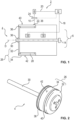
- a device 2 for dynamically balancing a rotating body 4 is shown schematically and in a simplified manner.
- the device 2 has an unbalance measuring device 6 for determining an unbalance of the rotating body 4.
- the device 2 also has a laser 8 for generating a laser beam 10, by means of which material of the rotating body 4 is removed and/or additional material is applied to the rotating body 4 depending on the determined unbalance.
- the unbalance measuring device 6 and the laser 8 are coupled by signal technology to a controller 12, i.e. a control unit.
- the rotary body 4 is rotatably mounted on both sides of its front sides in a bearing 14 of the unbalance measuring device 6 along its longitudinal axis, wherein in the Fig.1 only one bearing 14 is shown as an example.
- the unbalance measuring device 6 has at least one unbalance sensor 16, which detects the occurring unbalance of the rotating body 4, for example by force and/or distance measurement.
- the Fig.1 Two unbalance sensors 16 are shown as examples.
- the at least one unbalance sensor 16 sends the recorded data as unbalance signals 18 to the controller 12, which subsequently determines or calculates the unbalance of the rotating body 4 and the necessary unbalance compensation or the necessary unbalance correction.
- the Controller 12 determines in particular the position and location of the asymmetrical mass distribution. Then, using a laser signal 20, the laser 8 or the laser beam 10 is irradiated continuously or in pulsed form onto the rotating rotary body 4 in order to realize or implement the unbalance compensation.
- either material of the rotary body 4 is removed or removed by means of subtractive laser ablation, or additional material 22 is applied or added by means of laser deposition or laser deposition welding (LMD) in order to reduce the asymmetrical mass distribution of the rotary body 4.
- LMD laser deposition or laser deposition welding
- the laser beam 10 is moved over the outer circumference of the rotating body 4 by means of a deflection element 24 coupled to the controller 12.
- the deflection element 24 is suitably designed as a laser switch or a mirror.
- the laser beam 10 can be moved along an axial direction of the rotating body 4 by means of the deflection element 24, the laser beam 10 simultaneously being moved effectively along the tangential or circumferential direction of the rotating body 4 due to the rotation of the rotating body 4. This means that the application and/or removal takes place in particular in the radial and/or axial direction of the rotating body 4.
- axial or an “axial direction” is understood to mean in particular a direction parallel (coaxial) to the axis of rotation D of the rotating body 4.
- radial or a “radial direction” is understood to mean in particular a direction oriented perpendicular (transverse) to the axis of rotation D along the rotating body 4.
- tangential or a “tangential direction” is understood to mean in particular a direction along the circumference of the rotating body 4 (circumferential direction, azimuthal direction), i.e. a direction perpendicular to the axial direction and the radial direction.
- Laser 8 for example, is designed as a continuously operating fiber laser with a laser power of 12 kW and a wavelength of approximately 1060 nm.
- the laser beam 10 is in particular pulsed during the application or removal process, i.e. is irradiated in pulse form onto the rotating body 4. For example, pulse lengths or pulse durations between 0.1 - 10 ms (milliseconds) are provided.
- the application and/or removal by means of the laser beam 10 takes place in particular linearly along the circumferential or tangential direction of the rotating body 4.
- the laser 8 is in particular synchronized with the rotation of the rotating body 4 controlled by the unbalance measuring device 6.
- the removal and/or the application are therefore carried out by means of the device 2 during the rotation of the rotating body 4.
- the removal and/or the application are carried out during the determination of the unbalance.
- the dynamic balancing of the rotating body 4 is therefore carried out, for example, at the same time as the measurement or determination of the unbalance.
- the unbalance compensation or the unbalance correction is therefore carried out "on the fly”.
- the rotation body 4 is in the embodiments shown of the Figures 1 to 4 in particular as a rotationally symmetrical component of an electric motor of a motor vehicle (not shown in detail).
- the rotating body 4 is designed in particular as a motor housing 26, in particular as a pole pot, with a magnetic element 28 inserted therein, in particular a (motor) ring magnet, and with a motor shaft 30.
- the rotating body 4 is thus designed in particular as a rotor of an electric motor designed as an external rotor.
- the bell-shaped or pot-shaped motor housing 26 shown has a metal stamped part in the form of a bearing plate 32 as the housing base, and a metal, in particular hollow-cylindrical or tubular, annular wall 34 as the housing shell or housing wall.
- the motor shaft 30 has a diameter of between 2 and 10 mm (millimeters), for example, and is made of ground steel.
- the bearing plate 32 and the annular wall 34 as well as the motor shaft 30 are connected by means of material-locking connections 36 are joined together.
- the ring-shaped or hollow-cylindrical or tubular magnet element 28 is arranged on the inner circumference of the ring wall 34.
- the application and/or removal for unbalance correction takes place in an embodiment not according to the invention in two unbalance or compensation areas 38 and 40 on an outer circumference 42 of the motor housing 26.
- the approximately ring- or band-shaped unbalance areas 38 and 40 are arranged axially spaced from one another on the ring wall 34, the unbalance area 38 being arranged at the end facing away from the bearing plate 32 and the unbalance area 40 being arranged at the end of the ring wall 34 facing the bearing plate 32.
- the magnet element 28 has, for example, a maximum permissible temperature of about 120°C. In order to avoid an undesirable exceedance of this magnet temperature, particularly during a radial application of additional material 22, it is possible to Fig. 3 and Fig. 4 In the embodiment of the invention shown, an additional or balancing mass 44 is arranged on the outer circumference 42, onto which the application takes place. This reduces the energy and heat input to the ring wall 34 and thus to the magnetic element 28.
- the balancing mass 44 is suitably arranged in one of the unbalance areas 38, 40, wherein the balancing mass 44 in the embodiment of the Fig.3 and the Fig.4 in particular in the region 38.
- the balancing mass 44 has, for example, a mass between 5 to 20 mg (milligrams) and 100 to 300 mg.
- the balancing mass 44 is joined to the outer circumference 42 of the motor housing 26 in a material-locking manner, in particular by means of two welding points 46.
- the balancing mass 44 has an inner radius which is smaller than an outer radius of the outer circumference 42.
- the radius difference between the inner radius of the balancing mass 44 and the outer radius of the outer circumference 42 is, for example, less than or equal to 1 mm.
- the balancing mass 44 Due to the difference in radius, the balancing mass 44 has an approximately arcuate or curved cross-sectional shape, with the welding points 46 arranged in the area of the free ends of the arc arms.
- a radial clearance 48 i.e. a clear distance along the radial direction, is formed or exposed.
- This clearance 48 acts as thermal insulation between the balancing mass 44 and the ring wall 34 or the magnetic element 28. This creates a thermal decoupling between the balancing mass 28 and the rotating body 4, whereby the energy and heat input during the removal and/or application to the rotating body 4 is reduced.
- the ring wall 34 and the bearing plate 32 as well as the balancing mass 28 are made, for example, of steel, in particular stainless steel or carbon steel.
Landscapes
- Physics & Mathematics (AREA)
- General Physics & Mathematics (AREA)
- Engineering & Computer Science (AREA)
- Power Engineering (AREA)
- Manufacture Of Motors, Generators (AREA)
- Testing Of Balance (AREA)
Description
- Die Erfindung betrifft ein Verfahren zum dynamischen Wuchten eines Rotationskörpers, insbesondere eines Motorgehäuses eines Elektromotors. Die Erfindung betrifft weiterhin eine Vorrichtung zum dynamischen Wuchten eines Rotationskörpers, und einen Elektromotor mit einem Rotationskörper, welcher mit dem Verfahren gewuchtet ist, sowie eine Verwendung des Verfahrens zum dynamischen Wuchten eines Motorgehäuses mit einem darin eingesetzten Magnetelement.
- Rotierende oder rotationssymmetrische Bauteile weisen als Rotationskörper aufgrund von fertigungs- oder konstruktionsbedingten Toleranzen stets zumindest eine gewisse Unwucht auf. Unter einer Unwucht ist hierbei insbesondere eine unsymmetrische Massenverteilung des (rotationssymmetrischen) Rotationskörpers zu verstehen, wodurch dessen Rotationsachse nicht mit einer seiner Hauptträgheitsachsen zusammenfällt oder übereinstimmt. Bei einer Rotation des Rotationskörpers treten aufgrund der Unwucht sogenannte Unwuchtskräfte als Flieh- oder Zentrifugalkräfte auf, welche mit steigender Drehzahl zunehmen, und eine unrunde, eiernde Rotationsbewegung des Rotationskörpers bewirken. Dadurch entstehen im Betrieb ungewünschte Vibrationen und Geräuschentwicklungen aufgrund der Unwucht des Rotationskörpers.
- Durch die Unwucht kann die Lebensdauer eines das Bauteil oder den Rotationskörper aufweisenden Produktes und/oder die Lebensdauer von dem Rotationskörper rotierbar lagernden Lager reduziert werden. Des Weiteren besteht insbesondere bei hohen Drehzahlen die Gefahr, dass das Bauteil und/oder die Lager beschädigt oder vollständig zerstört werden.
- Insbesondere bei Elektromotoren eines Kraftfahrzeugs, welche beispielsweise im Bereich einer Fahrgastzelle angeordnet werden, ist ein möglichst geräuschreduzierter Betrieb gewünscht. Des Weiteren sollen derartige Elektromotoren möglichst bauraumkompakt sein, also eine möglichst geringe (Ein-)Baugröße aufweisen. Derartige Elektromotoren benötigen daher rotationssymmetrische Bauteile, wie beispielsweise Rotoren oder Motorgehäuse, welche eine möglichst geringe Unwucht aufweisen.
- Zur Beseitigung oder zur Korrektur von Unwuchten ist es möglich, den Rotationskörper oder das Bauteil zu wuchten. Bei einem Wuchten wird die unsymmetrische Massenverteilung des Rotationskörpers korrigiert oder ausgeglichen. Dies erfolgt beispielsweise durch ein Anbringen oder ein Aufbringen einer Zusatzmasse, oder durch ein Entfernen oder ein Abtragen einer Masse des Rotationskörpers, beispielsweise mittels spanender Verfahren. Dadurch wirken im Zuge des Wuchtens mechanische Kräfte auf den Rotationskörper ein.
- Bei einem (Aus-)Wuchten wird zwischen einem dynamischem und einem statischem Wuchten unterschieden. Bei einem statischen Wuchten wird lediglich ein statischer Anteil der Unwucht ausgeglichen, das Wuchten erfolgt also in einer Ebene. Bei dem dynamischen Wuchten wird sowohl der statische Unwuchtsanteil als auch ein dynamischer (Moment-)Unwuchtsanteil ausgeglichen. Hierbei wird sowohl eine radiale als auch axiale Lage der Unwucht am Rotationskörper beachtet und ausgeglichen. Das Wuchten erfolgt also in zwei Ebenen des Rotationskörpers. Durch das dynamische Wuchten wird somit eine eiernde, unrunde Rotationsbewegung verhindert oder zumindest wesentlich reduziert.
- Insbesondere bei vergleichsweise hohen Anforderungen an die Geräuscharmut und Lebensdauer von bauraumkompakter Elektromotoren treten bei herkömmlichen Wuchtverfahren Probleme auf. In der Regel wird die Unwucht des Rotationskörpers oder Bauteils vor und nach dem Wuchten mittels einer Unwuchtmessvorrichtung bestimmt, und in Abhängigkeit hiervon Material bzw. Masse am Rotationskörper auf- oder abgetragen. Das Wuchten und die Messung der Unwucht erfolgt regelmäßig in getrennten Vorrichtungen, wodurch ein gleichförmiger Produktionsfluss bei der Herstellung des Elektromotors beziehungsweise des Bauteils nachteilig erschwert wird.
- Die
US 2007/0095231 A1 offenbart eine Vorrichtung zum Auswuchten einer Druckwalze, die einen Detektor zum Erkennen einer Unwucht der Druckwalze während ihrer Drehung enthält. Ein Computer bestimmt als Reaktion auf die erkannte Unwucht eine Gewichtseinstellung, welche zur Korrektur der Unwucht erforderlich ist. Ein Laser wird vom Computer gesteuert, um als Reaktion auf die Bestimmung Material von mindestens einer gravierbaren Platte, die auf der Außenfläche der Druckwalze angebracht ist, oder von der Druckwalze selbst in einem Bereich zu entfernen, um die Druckwalze auszuwuchten. - In der
WO 2007/006356 A1 ist ein Verfahren zum Wuchten eines Lüfters mittels eines außerhalb des Lüfters angeordneten, steuerbaren Lasers offenbart. Ein Lüftergehäuse zumindest in einem Gehäuse-Teilbereich derart ausgebildet, dass es eine Bearbeitung eines Rotors durch einen vom Laser ausgehenden, sich durch den Gehäuse-Teilbereich zum Rotor erstreckenden Laserstrahl ermöglicht. - Aus der
DE 10 2008 053 838 A1 ist ein Verfahren und eine Vorrichtung zum Wuchten eines Rotationskörpers bekannt. Hierbei wird mindestens ein Wuchtgewicht durch Reibschweißen an dem Rotationskörper angebracht. - Die
US 2018/0051771 A1 beschreibt eine Antriebswelle mit aufgeschweißten Ausgleichsgewicht und Verfahren zu deren Herstellung. Ein Lack wird hierbei von der Antriebswelle entfernt, bevor das Ausgleichsgewicht aufgeschweißt wird. Das Entlacken und Schweißen kann in das Auswuchtverfahren und die Auswuchtvorrichtung integriert sein. - Der Erfindung liegt die Aufgabe zugrunde, ein besonders geeignetes Verfahren zum dynamischen Wuchten eines Rotationskörpers anzugeben. Der Erfindung liegt weiterhin die Aufgabe zugrunde, eine besonders geeignete Vorrichtung zur Durchführung des Verfahrens anzugeben. Der Erfindung liegt weiterhin die Aufgabe zugrunde, einen besonders geeigneten Elektromotor mit einem Rotationskörper, welcher mit einem derartigen Verfahren gewuchtet ist, sowie eine besonders geeignete Verwendung eines solchen Verfahrens zum dynamischen Wuchten eines Motorgehäuses mit einem darin eingesetzten Magnetelement anzugeben.
- Hinsichtlich des Verfahrens wird die Aufgabe mit den Merkmalen des Anspruchs 1 und hinsichtlich der Vorrichtung mit den Merkmalen des Anspruchs 5 sowie hinsichtlich des Elektromotors mit den Merkmalen des Anspruchs 6 und hinsichtlich der Verwendung mit den Merkmalen des Anspruchs 7 erfindungsgemäß gelöst. Vorteilhafte Ausgestaltungen und Weiterbildungen sind Gegenstand der jeweiligen Unteransprüche. Die im Hinblick auf das Verfahren angeführten Vorteile und Ausgestaltungen sind sinngemäß auch auf die Vorrichtung und/oder den Elektromotor und/oder die Verwendung übertragbar und umgekehrt.
- Das erfindungsgemäße Verfahren ist zum dynamischen Wuchten eines Rotationskörpers, also eines rotationssymmetrischen Bauteils oder Werkstücks, geeignet und ausgestaltet. Der Rotationskörper ist beispielsweise ein Bauteil eines Elektromotors, insbesondere ein Rotor oder ein Motorgehäuse.
- Verfahrensgemäß wird der Rotationskörper in Rotation versetzt und anschließend dessen Unwucht bestimmt. In Abhängigkeit der bestimmten Unwucht wird Material von der Wuchtmasse abgetragen und/oder Zusatzmaterial auf der Wuchtmasse aufgetragen. In Abhängigkeit der erfassten oder bestimmten Unwucht wird also ein Unwuchtsausgleich oder eine Unwuchtskorrektur zur Reduzierung der Unwucht, also zur Reduzierung einer unsymmetrischen Masseverteilung des Rotationskörpers ausgeführt. Die Konjunktion "und/oder" ist hier und im Folgenden derart zu verstehen, dass die mittels dieser Konjunktion verknüpften Merkmale sowohl gemeinsam als auch als Alternativen zueinander ausgebildet sein können.
- Der Unwuchtsausgleich oder die Unwuchtskorrektur, also die Abtragung und/oder Auftragung von Material von von (an der) Wuchtmasse, wird hierbei mittels eines Laserstrahls eines Lasers durchgeführt. Dadurch ist ein besonders geeignetes Verfahren zum Wuchten eines Rotationskörpers realisiert.
- Durch den Laser beziehungsweise den Laserstrahl ist ein besonders genaues oder präzises Wuchten des Rotationskörpers ermöglicht. Dadurch können auch kleine Unwuchten zuverlässig beseitigt werden. Durch den Laser ist somit eine besonders hohe Wuchtgüte des Rotationskörpers realisierbar. Des Weiteren wirken bei einem solchen Laserwuchten keine zusätzlichen mechanischen Kräfte auf den Rotationskörper ein.
- Die Abtragung erfolgt also insbesondere mittels eines (subtraktiven, negativen) Laserabtrags, wobei die Auftragung insbesondere mittels eines (additiven, positiven) Laserauftrags oder Laserauftragsschweißen (engl.: laser metal deposition, LMD) erfolgt. Beim Auftragen wird das Zusatzmaterial beispielsweise in Form eines Drahtes oder Metallpulvers zugeführt und schichtweise auf den Rotationskörper aufgetragen sowie poren- und rissfrei mittels des Laserstrahls mit dem Material des Rotationskörpers stoffschlüssig gefügt oder verschmolzen.
- Das erfindungsgemäße Verfahren ist insbesondere zum Feinwuchten des Rotationskörpers vorgesehen, also zur Korrektur oder Ausgleich vergleichsweise geringer Unwuchten oder vergleichsweise geringer unsymmetrischer Masseverteilungen. Bei größeren Unwuchten ist es hierbei insbesondere möglich, dass ein zweistufiges Wuchtverfahren vorgesehen ist, bei welchen in einem groben Verfahrensschritt die Unwucht beispielsweise mittels spanenden Verfahren reduziert wird, und bei welchen in einem darauffolgenden zweiten, feineren Verfahrensschritt das erfindungsgemäße Verfahren angewandt wird.
- In einer vorteilhaften Ausführung werden die Abtragung und/oder die Auftragung während der Rotation des Rotationskörpers durchgeführt. Insbesondere werden die Abtragung und/oder die Auftragung hierbei beispielsweise während der Bestimmung der Unwucht durchgeführt. Das dynamische Wuchten des Rotationskörpers erfolgt also im Wesentlichen zeitgleich zur Messung oder Bestimmung der Unwucht. Dies bedeutet, dass der Rotationskörper beispielsweise zeitgleich gemessen und gewuchtet wird. Dadurch ist ein integrierter gesteuerter Prozess realisierbar.
- In einer möglichen Ausführungsform erfolgt die Abtragung insbesondere während einer Rotation des Rotationskörpers mit einer Nenndrehzahl. Durch die vergleichsweise schnelle Rotation des Rotationskörpers während der Abtragung wirkt ein besonders niedriger Energie- oder Wärmeeintrag auf das Bauteil beziehungsweise den Rotationskörper ein, so dass im Wesentlichen kein Verzug des Rotationskörpers bei der Abtragung auftritt.
- Die Auftragung erfolgt insbesondere bei einer Rotation des Rotationskörpers mit einer Drehzahl, welche wesentlich niedriger als die Nenndrehzahl während der Auftragung ist. Die Drehzahl während der Abtragung ist beispielsweise zwischen größer 0% (Stillstand) und 10% der Nenndrehzahl, insbesondere zwischen größer 0% und 5% der Nenndrehzahl, vorzugsweise zwischen größer 0% und 2% der Nenndrehzahl. Die Auftragung oder das positive Wuchten erfolgt also nicht im Stillstand des Rotationskörpers, sondern bei einer im Vergleich zur Nenndrehzahl reduzierten, langsamen Rotation.
- Der Unwuchtsausgleich oder die Unwuchtskorrektur erfolgt also während der Rotationskörper rotiert wird. Das Wuchten wird somit "on-the-fly" durchgeführt, wodurch eine besonders gleichförmige Produktion und Herstellung des Rotationskörpers ermöglicht ist.
- In einer zweckmäßigen Ausgestaltung des Verfahrens wird das Zusatzmaterial linien- oder streifenförmig aufgetragen. Dadurch ist eine hinsichtlich des Wärmeeintrags in den Rotationskörper besonders effektive und zweckmäßige Auftragung des Zusatzmaterials realisiert.
- In einer geeigneten Weiterbildung wird der Laserstrahl bei der Abtragung und/oder bei der Auftragung mittels eines Ablenkelements über den Außenumfang des Rotationskörpers bewegt. Das Ablenkelement ist hierbei geeigneterweise eine Laserweiche oder ein Spiegel. Dadurch wird die Effizienz des Verfahrens wesentlich verbessert, da der Laserstrahl nicht lediglich an einer Stelle des Rotationskörpers angeordnet ist, sondern insbesondere bei gleichzeitiger Rotation des Rotationskörpers, im Wesentlichen über dessen kompletten Außenumfang bewegt werden kann. Dies bedeutet, dass der Laserstrahl mittels des Ablenkelements insbesondere entlang einer Axialrichtung des Rotationskörpers bewegt wird, wobei der Laserstrahl aufgrund der Rotation des Rotationskörpers effektiv entlang dessen Tangential- oder Umfangsrichtung bewegt wird.
- In einer alternativen Weiterbildungsform ist es beispielsweise denkbar, dass der Laserstrahl beziehungsweise der Laser selbst mittels eines Scanners über den Außenumfang des Rotationskörpers bewegt wird.
- Erfindungsgemäß wird eine Wuchtmasse an einem Außenumfang des Rotationskörpers befestigt, wobei die Abtragung und/oder Auftragung mittels des Laserstrahls lediglich auf der Wuchtmasse erfolgt. Dadurch wird der Energie- und Wärmeeintrag auf den Rotationskörper selbst reduziert. Eine derartige separate Wuchtmasse ist insbesondere bei Rotationskörpern vorteilhaft, bei welchen eine Erwärmung des Materials des Rotationskörpers im Bereich des Laserstrahls nachteilige Auswirkungen hat.
- Erfindungsgemäß ist die Wuchtmasse zum Zwecke einer zuverlässigen und dauerhaften Befestigung stoffschlüssig mittels Schweißens an den Außenumfang des Rotationskörpers gefügt. Dadurch ist eine betriebssichere Befestigung der Wuchtmasse, auch bei hohen Drehzahlen des Rotationskörpers gewährleistet.
- Unter einem "Stoffschluss" oder einer "stoffschlüssigen Verbindung" zwischen wenigstens zwei miteinander verbundenen Teilen wird hier und im Folgenden insbesondere verstanden, dass die miteinander verbundenen Teile an Ihren Kontaktflächen durch stoffliche Vereinigung oder Vernetzung (beispielsweise aufgrund von atomaren oder molekularen Bindungskräften) gegebenenfalls unter Wirkung eines Zusatzstoffs zusammengehalten werden.
- Erfindungsgemäß wird hierbei eine Wuchtmasse befestigt, deren Innenradius kleiner als ein Außenradius des Außenumfangs bemessen ist. Dies bedeutet, dass die Wuchtmasse eine etwa bogenförmige Querschnittsform aufweist, wobei die Wuchtmasse lediglich im Bereich der Freienden der Bogenarme an dem Außenumfang des Rotationskörpers anliegt. Somit ist im Bereich eines Scheitelpunktes der Wuchtmasse zwischen dem Rotationskörper und der Wuchtmasse ein Freiraum, also ein lichter Abstand gebildet. Dieser Freiraum oder Abstand wirkt als thermische Isolierung zwischen der Wuchtmasse und dem Rotationskörper. Dadurch wird eine thermische Entkopplung zwischen Wuchtmasse und Rotationskörper realisiert, wodurch der Energie- und Wärmeeintrag im Zuge des Abtragens und/oder Auftragens auf den Rotationskörper weiter reduziert wird.
- Die erfindungsgemäße Vorrichtung ist zum dynamischen Wuchten eines Rotationskörpers geeignet und eingerichtet. Eine bogenförmige Wuchtmasse mit einem Innenradius, welcher kleiner als ein Außenradius eines Außenumfangs des Rotationskörpers ist, wird im Bereich der Freienden der Bogenarme an einem Außenumfang des Rotationskörper stoffschlüssig geschweißt, so dass durch den Radiusunterschied im Bereich eines Scheitelpunktes der Wuchtmasse zwischen der Wuchtmasse und dem Rotationskörper ein Freiraum als thermische Isolierung gebildet ist. Die Vorrichtung weist hierbei eine Unwuchtmessvorrichtung zur Bestimmung einer Unwucht des Rotationsköpers auf. Die Vorrichtung weist weiterhin einen Laser zur Erzeugung eines Laserstrahls auf, mittels welchem Material der Wuchtmasse abtragbar und/oder Zusatzmaterial auf die Wuchtmasse auftragbar ist. Die Unwuchtmessvorrichtung und der Laser sind mit einem Controller, also einer Steuereinheit, gekoppelt.
- Der Controller ist hierbei allgemein - programm- und/oder schaltungstechnisch - zur Durchführung des vorstehend beschriebenen erfindungsgemäßen Verfahrens eingerichtet. Der Controller ist somit konkret dazu eingerichtet, anhand von Unwuchtdaten der Unwuchtmessvorrichtung die Unwucht des Rotationskörpers, also die Position und Lage der unsymmetrischen Masseverteilung, zu bestimmen, und einen benötigten Unwuchtausgleich oder eine Unwuchtskorrektur zu berechnen, sowie die Unwucht durch Ansteuerung des Lasers zu reduzieren.
- In einer bevorzugten Ausgestaltungsform ist der Controller zumindest im Kern durch einen Mikrocontroller mit einem Prozessor und einem Datenspeicher gebildet, in dem die Funktionalität zur Durchführung des erfindungsgemäßen Verfahrens in Form einer Betriebssoftware (Firmware) programmtechnisch implementiert ist, so dass das Verfahren - gegebenenfalls in Interaktion mit einem Vorrichtungsnutzer - bei Ausführung der Betriebssoftware in dem Mikrocontroller automatisch durchgeführt wird. Der Controller kann im Rahmen der Erfindung alternativ aber auch durch ein nicht-programmierbares elektronisches Bauteil, wie zum Beispiel einem anwendungsspezifischen integrierten Schaltkreis (ASIC), gebildet sein, in dem die Funktionalität zur Durchführung des erfindungsgemäßen Verfahrens mit schaltungstechnischen Mitteln implementiert ist.
- Die Unwuchtmessvorrichtung weist hierbei beispielsweise eine Aufnahme für den Rotationskörper auf, und rotiert diesen im Betrieb, wobei mittels Kraftsensoren die auftretenden Unwuchtkäfte erfasst werden. Aus den aufgenommenen Kraftsignalen bestimmt oder berechnet der Controller die Unwucht des rotierenden Rotationskörpers sowie den notwendigen Unwuchtsausgleich. Im Wesentlichen zeitgleich wird der Laserstrahl kontinuierlich oder gepulst auf den sich insbesondere drehenden Rotationskörper eingestrahlt, um den Unwuchtsausgleich zu realisieren oder umzusetzen.
- Der Laser ist beispielsweise als kontinuierlich arbeitender Faserlaser mit einer Laserleistung von beispielsweise 12 kW (Kilowatt) ausgeführt, wobei die Wellenlänge insbesondere an das abzutragende und/oder aufzutragende Material des Rotationskörpers bzw. des Zusatzmaterials angepasst ist. Beispielsweise wird bei einem Kohlenstoffstahl insbesondere ein Faserlaser mit einer Wellenlänge von etwa 1060 nm (Nanometer) verwendet.
- Der Laserstrahl wird hierbei im Zuge des Auftragens oder Abtragens insbesondere gepulst, also impulsförmig auf den Rotationskörper oder das Zusatzmaterial eingestrahlt. Hierbei sind beispielsweise Pulslängen oder Pulsdauern von Einzelpulsen des Lasers vorgesehen, welche vorzugsweise kleiner 100 µs (Mikrosekunden) sind. Mehrere Einzelpulse können hintereinander als ein Pulspaket oder als eine Pulsfolge zur Abtragung oder Auftragung erzeugt werden, beispielsweise mit einer Pulspaketdauer von bis zu 10 ms (Millisekunden). Der Laser ist hierbei zweckmäßigerweise mit der Unwuchtmessvorrichtung synchronisiert.
- Der erfindungsgemäße Elektromotor ist für ein Kraftfahrzeug vorgesehen, und weist einen Rotationskörper auf, welcher nach dem vorstehend beschriebenen Verfahren dynamisch gewuchtet ist. Der Rotationskörper ist hierbei beispielsweise ein Motorgehäuse, insbesondere ein Poltopf, mit einem darin eingesetzten Magnetelement, insbesondere einem Motorringmagneten. Der Elektromotor ist hierbei beispielsweise als ein Außenläufer für einen elektromotorischen Verstellantrieb des Kraftfahrzeugs ausgebildet, beispielsweise für einen Kühlerlüfter oder für einen Fensterheber, wobei das Motorgehäuse mit dem Motorringmagnet insbesondere als ein Rotor des Elektromotors ausgeführt ist.
- Das Magnetelement ist hierbei vergleichsweise temperaturempfindlich, da beispielsweise bei Temperaturen über 120°C Entmagnetisierungseffekte auftreten können. Durch das erfindungsgemäße Verfahren ist ein besonders niedriger Wärmeeintrag auf das Motorgehäuse und das Magnetelement gewährleistet, wodurch der Rotationskörper in einfacher und zuverlässiger Weise dynamisch gewuchtet ist. Dadurch ist eine besonders gleichförmige Produktion und Herstellung des Rotationskörpers, und somit des Elektromotors ermöglicht.
- In einer bevorzugten Anwendung wird das vorstehend beschriebene Verfahren nach somit insbesondere zum dynamischen Auswuchten eines Motorgehäuses mit einem darin eingesetzten Magnetelement verwendet.
- Nachfolgend sind Ausführungsbeispiele der Erfindung anhand einer Zeichnung näher erläutert. Darin zeigen in schematischen und vereinfachten Darstellungen:
- Fig. 1
- in Teil-Schnittansicht eine Vorrichtung zum dynamischen Wuchten eines Motorgehäuses als Rotationskörper,
- Fig. 2
- in perspektivischer Ansicht das Motorgehäuse mit einer Welle,
- Fig. 3
- in perspektivischer Ansicht das Motorgehäuse mit einer Wuchtmasse, und
- Fig. 4
- in Teil-Schnittansicht das Motorgehäuse mit der Wuchtmasse entlang der Linie IV-IV gemäß
Fig. 3 . - Einander entsprechende Teile und Größen sind in allen Figuren stets mit den gleichen Bezugszeichen versehen.
- In der
Fig. 1 ist eine Vorrichtung 2 zum dynamischen Wuchten eines Rotationskörpers 4 schematisch und vereinfacht dargestellt. Die Vorrichtung 2 weist hierbei eine Unwuchtmessvorrichtung 6 zur Bestimmung einer Unwucht des Rotationsköpers 4 auf. Die Vorrichtung 2 weist weiterhin einen Laser 8 zur Erzeugung eines Laserstrahls 10 auf, mittels welchem in Abhängigkeit der bestimmten Unwucht Material des Rotationskörpers 4 abgetragen und/oder Zusatzmaterial auf den Rotationskörper 4 aufgetragen wird. Die Unwuchtmessvorrichtung 6 und der Laser 8 sind mit einem Controller 12, also einer Steuereinheit, signaltechnisch gekoppelt. - Vorzugsweise ist der Rotationskörper 4 beidseitig an seinen Stirnseiten jeweils in einem Lager 14 der Unwuchtmessvorrichtung 6 entlang seiner Längsachse drehbar gelagert, wobei in der
Fig. 1 beispielhaft lediglich ein Lager 14 gezeigt ist. - Die Unwuchtmessvorrichtung 6 weist mindestens einen Unwuchtsensor 16 auf, welcher die auftretende Unwucht des rotierenden Rotationskörpers 4 beispielsweise durch Kraft- und/oder Wegmessung erfasst. In der
Fig. 1 sind beispielhaft zwei Unwuchtsensoren 16 gezeigt. - Der mindestens eine Unwuchtsensor 16 sendet die aufgenommenen Daten als Unwuchtsignale 18 an den Controller 12, welcher in der Folge die Unwucht des rotierenden Rotationskörpers 4 sowie den notwendigen Unwuchtsausgleich beziehungsweise die notwendige Unwuchtskorrektur bestimmt oder berechnet. Der Controller 12 bestimmt hierbei insbesondere die Position und Lage der unsymmetrischen Masseverteilung. Anschließend wird mittels eines Lasersignals 20 der Laser 8 beziehungsweise der Laserstrahl 10 kontinuierlich oder gepulst auf den sich drehenden Rotationskörper 4 eingestrahlt, um den Unwuchtsausgleich zu realisieren oder umzusetzen. Hierbei wird je nach notwendigen Unwuchtsausgleich in einer nicht erfindungsgemäße Ausführung entweder Material des Rotationskörper 4 mittels subtraktiven Laserabtrags abgetragen oder entfernt, oder Zusatzmaterial 22 mittels Laserauftrags oder Laserauftragsschweißen (LMD) aufgetragen oder hinzugefügt, um die unsymmetrischen Masseverteilung des Rotationskörpers 4 zu reduzieren.
- Der Laserstrahl 10 wird bei der Abtragung und/oder bei der Auftragung mittels eines mit dem Controller 12 gekoppelten Ablenkelements 24 über den Außenumfang des Rotationskörpers 4 bewegt. Das Ablenkelement 24 ist geeigneterweise als eine Laserweiche oder ein Spiegel ausgebildet. Mittels des Ablenkelements 24 ist der Laserstrahl 10 entlang einer Axialrichtung des Rotationskörpers 4 bewegbar, wobei der Laserstrahl 10 gleichzeitig aufgrund der Rotation des Rotationskörpers 4 effektiv entlang dessen Tangential- oder Umfangsrichtung bewegt wird. Dies bedeutet, dass die Auftragung und/oder die Abtragung insbesondere in radialer und/oder axialer Richtung des Rotationskörpers 4 erfolgen.
- Unter "axial" oder einer "Axialrichtung" wird hier und im Folgenden insbesondere eine Richtung parallel (koaxial) zur Drehachse D des Rotationskörpers 4 verstanden. Entsprechend wird hier und im Folgenden unter "radial" oder einer "Radialrichtung" insbesondere eine senkrecht (quer) zur Drehachse D orientierte Richtung entlang des Rotationskörpers 4 verstanden. Unter "tangential" oder einer "Tangentialrichtung" wird hier und im Folgenden insbesondere eine Richtung entlang des Umfangs des Rotationskörpers 4 (Umfangsrichtung, Azimutalrichtung), also eine Richtung senkrecht zur Axialrichtung und zur Radialrichtung, verstanden.
- Der Laser 8 ist beispielsweise als kontinuierlich arbeitender Faserlaser mit einer Laserleistung von 12 kW und mit einer Wellenlänge von etwa 1060 nm ausgeführt.
- Der Laserstrahl 10 wird hierbei im Zuge des Auftragens oder Abtragens insbesondere gepulst, also impulsförmig auf den Rotationskörper 4 eingestrahlt. Hierbei sind beispielsweise Pulslängen oder Pulsdauern zwischen 0,1 - 10 ms (Millisekunden) vorgesehen. Die Auftragung und/oder die Abtragung mittels des Laserstrahls 10 erfolgt hierbei insbesondere linienförmig entlang der Umfangs- oder Tangentialrichtung des Rotationskörpers 4. Der Laser 8 ist hierbei insbesondere mit der Rotation durch die Unwuchtmessvorrichtung 6 gesteuerten Rotation des Rotationskörpers 4 synchronisiert.
- Die Abtragung und/oder die Auftragung werden also mittels der Vorrichtung 2 während der Rotation des Rotationskörpers 4 durchgeführt. Insbesondere werden die Abtragung und/oder die Auftragung hierbei während der Bestimmung der Unwucht durchgeführt. Das dynamische Wuchten des Rotationskörpers 4 erfolgt also beispielsweise zeitgleich zur Messung oder Bestimmung der Unwucht. Der Unwuchtsausgleich oder die Unwuchtskorrektur erfolgt also somit "on-the-fly".
- Der Rotationskörper 4 ist in den gezeigten Ausführungsbeispielen der
Figuren 1 bis 4 insbesondere als ein rotationssymmetrisches Bauteil eines nicht näher gezeigten Elektromotors eines Kraftfahrzeugs ausgebildet. Der Rotationskörper 4 ist insbesondere als ein Motorgehäuse 26, insbesondere als ein Poltopf, mit einem darin eingesetzten Magnetelement 28, insbesondere einem (Motor-)Ringmagneten, und mit einer Motorwelle 30 ausgeführt. Der Rotationskörper 4 ist somit insbesondere als ein Rotor eines als Außenläufer ausgeführten Elektromotors ausgebildet. - Das in
Fig. 2 bis 4 dargestellte glockenförmige oder topfförmige Motorgehäuse 26 weist ein metallisches Stanzteil in Form eines Lagerschilds 32 als Gehäuseboden, und eine metallische, insbesondere hohlzylindrische oder rohrförmige, Ringwand 34 als Gehäusemantel oder Gehäusewand auf. Die Motorwelle 30 weist hierbei beispielsweise einen Durchmesser zwischen 2 bis 10 mm (Millimeter) auf, und ist aus einem geschliffenen Stahl hergestellt. Das Lagerschild 32 und die Ringwand 34 sowie die Motorwelle 30 sind mittels stoffschlüssigen Verbindungen 36 miteinander gefügt. Das ringförmige oder hohlzylindrische beziehungsweise rohrförmige Magnetelement 28 ist am Innenumfang der Ringwand 34 angeordnet. - Das Auftragen und/oder Abtragen zur Unwuchtskorrektur erfolgt hierbei in einer nicht erfindungsgemäßen Ausführung in zwei Unwuchts- oder Ausgleichsbereichen 38 und 40 an einem Außenumfang 42 des Motorgehäuses 26. Die etwa ring- oder bandförmigen Unwuchtsbereiche 38 und 40 sind axial zueinander beabstandet an der Ringwand 34 angeordnet, wobei der Unwuchtsbereich 38 an der dem Lagerschild 32 abgewandten Ende, und der Unwuchtsbereich 40 an der dem Lagerschild 32 zugewandten Ende der Ringwand 34 angeordnet ist.
- Das Magnetelement 28 weist beispielsweise eine maximal zulässige Temperatur von etwa 120°C auf. Um insbesondere im Zuge einer radialen Auftragung von Zusatzmaterial 22 eine ungewünschte Überschreitung dieser Magnettemperatur zu vermeiden, ist es in dem in
Fig. 3 und Fig. 4 gezeigten erfindungsgemäßen Ausführungsbeispiel vorgesehen, dass an dem Außenumfang 42 eine Zusatz- oder Wuchtmasse 44 angeordnet wird, auf welcher die Auftragung erfolgt. Dadurch wird der Energie- und Wärmeeintrag auf die Ringwand 34 und somit auf das Magnetelement 28 reduziert. - Die Wuchtmasse 44 ist hierbei geeigneterweise in einem der Unwuchtsbereiche 38, 40 angeordnet, wobei die Wuchtmasse 44 in dem Ausführungsbeispiel der
Fig. 3 und derFig. 4 insbesondere im Bereich 38 angeordnet ist. In einer geeigneten Dimensionierung weist die Wuchtmasse 44 beispielsweise eine Masse zwischen 5 bis 20 mg (Milligramm) und 100 bis 300 mg auf. - Wie insbesondere in der schematischen Teil-Schnittansicht der
Fig. 4 ersichtlich ist, ist die Wuchtmasse 44 insbesondere mittels zweier Schweißpunkte 46 stoffschlüssig an den Außenumfang 42 des Motorgehäuses 26 gefügt. Die Wuchtmasse 44 weist hierbei einen Innenradius auf, welcher kleiner dimensioniert ist als ein Außenradius des Außenumfangs 42. Der Radiusunterschied zwischen dem Innenradius der Wuchtmasse 44 und dem Außenradius des Außenumfangs 42 ist beispielsweise kleiner gleich 1 mm. - Durch den Radiusunterschied weist die Wuchtmasse 44 eine etwa bogenförmige oder gewölbte Querschnittsform auf, wobei die Schweißpunkte 46 im Bereich der Freienden der Bogenarme angeordnet sind. Somit ist im Bereich eines Scheitelpunktes der Wuchtmasse 44 zwischen der Ringwand 34 und der Wuchtmasse 44 ein radialer Freiraum 48, also ein lichter Abstand entlang der Radialrichtung, gebildet oder freigestellt. Dieser Freiraum 48 wirkt als thermische Isolierung zwischen der Wuchtmasse 44 und der Ringwand 34 beziehungsweise dem Magnetelement 28. Dadurch wird eine thermische Entkopplung zwischen Wuchtmasse 28 und Rotationskörper 4 realisiert, wodurch der Energie- und Wärmeeintrag im Zuge des Abtragens und/oder Auftragens auf den Rotationskörper 4 reduziert wird.
- Die Ringwand 34 und das Lagerschild 32 sowie die Wuchtmasse 28 sind beispielsweise aus Stahl, insbesondere Edelstahl oder Kohlenstoffstahl (Karbonstahl), hergestellt.
-
- 2
- Vorrichtung
- 4
- Rotationskörper
- 6
- Unwuchtmessvorrichtung
- 8
- Laser
- 10
- Laserstrahl
- 12
- Controller
- 14
- Lager
- 16
- Unwuchtsensor
- 18
- Kraftsignal
- 20
- Lasersignal
- 22
- Zusatzmaterial
- 24
- Ablenkelement
- 26
- Motorgehäuse
- 28
- Magnetelement
- 30
- Motorwelle
- 32
- Lagerschild
- 34
- Ringwand
- 36
- Verbindung
- 38
- Unwuchtsbereich
- 40
- Unwuchtsbereich
- 42
- Außenumfang
- 44
- Wuchtmasse
- 46
- Schweißpunkt
- 48
- Freiraum
- D
- Drehachse
Claims (7)
- Verfahren zum dynamischen Wuchten eines Rotationskörpers (4),- wobei eine bogenförmige Wuchtmasse (44) im Bereich der Freienden der Bogenarme der bogenförmigen Wuchtmasse (44) mit jeweils einem Schweißpunkt (46) stoffschlüssig mittels Schweißen an einem Außenumfang (42) des Rotationskörpers (4) befestigt wird,- wobei die Wuchtmasse (44) einen Innenradius aufweist, welcher kleiner als ein Außenradius des Außenumfangs (42) ist, so dass durch den Radiusunterschied im Bereich eines Scheitelpunktes der Wuchtmasse (44) zwischen der Wuchtmasse (44) und dem Rotationskörper (4) ein Freiraum als thermische Isolierung gebildet ist,- wobei der Rotationskörper (4) in Rotation versetzt wird,- wobei eine Unwucht des Rotationsköper (4) bestimmt wird,- wobei in Abhängigkeit der bestimmten Unwucht Material auf der Wuchtmasse (44) abgetragen und/oder Zusatzmaterial (22) auf der Wuchtmasse (44) aufgetragen wird, und- wobei die Abtragung und/oder die Auftragung mittels eines Laserstrahls (10) eines Lasers (8) durchgeführt werden.
- Verfahren nach Anspruch 1,
dadurch gekennzeichnet,
dass die Abtragung und/oder die Auftragung während der Rotation des Rotationskörpers (4) durchgeführt werden. - Verfahren nach Anspruch 1 oder 2,
dadurch gekennzeichnet,
dass das Zusatzmaterial (22) linienförmig aufgetragen wird. - Verfahren nach einem der Ansprüche 1 bis 3,
dadurch gekennzeichnet,
dass der Laserstrahl (10) bei der Abtragung und/oder bei der Auftragung mittels eines Ablenkelements (24) über einen Außenumfang (42) des Rotationskörpers (4) bewegt wird. - Vorrichtung (2) zum dynamischen Wuchten eines Rotationskörpers (4), aufweisend- eine bogenförmige Wuchtmasse (44) mit einem Innenradius, welcher kleiner als ein Außenradius eines Außenumfangs (42) des Rotationskörpers (4) ist,- eine Schweißeinheit zum stoffschlüssigen Schweißen der Wuchtmasse (44) im Bereich der Freienden der Bogenarme an dem Außenumfang (42), so dass durch den Radiusunterschied im Bereich eines Scheitelpunktes der Wuchtmasse (44) zwischen der Wuchtmasse (44) und dem Rotationskörper (4) ein Freiraum als thermische Isolierung gebildet ist,- eine Unwuchtmessvorrichtung (6) zur Bestimmung einer Unwucht des Rotationsköpers (4),- einen Laser (8) zur Erzeugung eines Laserstrahls (10), mittels welchem Material der Wuchtmasse (44) abtragbar und/oder Zusatzmaterial (22) auf die Wuchtmasse (44) auftragbar ist, und- einen Controller (12) zur Durchführung des Verfahrens nach einem der Ansprüche 1 bis 4.
- Elektromotor eines Kraftfahrzeugs, aufweisend einen Rotationskörper (4), welcher mit einem Verfahren nach einem der Ansprüche 1 bis 4 dynamisch gewuchtet ist.
- Verwendung des Verfahrens nach einem der Ansprüche 1 bis 4 zum dynamischen Wuchten eines Rotationskörpers (4), welcher als ein Motorgehäuse (26) mit einem darin eingesetzten Magnetelement (28) ausgeführt ist.
Applications Claiming Priority (2)
| Application Number | Priority Date | Filing Date | Title |
|---|---|---|---|
| DE102019207940.7A DE102019207940A1 (de) | 2019-05-29 | 2019-05-29 | Verfahren zum dynamischen Wuchten eines Rotationskörpers |
| PCT/EP2020/064619 WO2020239793A1 (de) | 2019-05-29 | 2020-05-27 | Verfahren zum dynamischen wuchten eines rotationskörpers |
Publications (3)
| Publication Number | Publication Date |
|---|---|
| EP3942269A1 EP3942269A1 (de) | 2022-01-26 |
| EP3942269C0 EP3942269C0 (de) | 2024-08-21 |
| EP3942269B1 true EP3942269B1 (de) | 2024-08-21 |
Family
ID=70861487
Family Applications (1)
| Application Number | Title | Priority Date | Filing Date |
|---|---|---|---|
| EP20728732.7A Active EP3942269B1 (de) | 2019-05-29 | 2020-05-27 | Verfahren zum dynamischen wuchten eines rotationskörpers |
Country Status (6)
| Country | Link |
|---|---|
| US (1) | US12081101B2 (de) |
| EP (1) | EP3942269B1 (de) |
| CN (1) | CN113874697B (de) |
| DE (1) | DE102019207940A1 (de) |
| MA (1) | MA55373A (de) |
| WO (1) | WO2020239793A1 (de) |
Families Citing this family (2)
| Publication number | Priority date | Publication date | Assignee | Title |
|---|---|---|---|---|
| DE102021133851A1 (de) | 2021-12-20 | 2023-06-22 | Messer Cutting Systems Gmbh | Vorrichtung für die thermische Bearbeitung eines Werkstücks mit Laserstrahlung sowie dafür geeignete Schutzhaube |
| CN114459685A (zh) * | 2022-01-29 | 2022-05-10 | 西安电子科技大学 | 一种转子不平衡激光动态校正系统及其控制方法 |
Family Cites Families (27)
| Publication number | Priority date | Publication date | Assignee | Title |
|---|---|---|---|---|
| US3663795A (en) * | 1968-10-28 | 1972-05-16 | Hughes Aircraft Co | Rotor balancer |
| DE2032893A1 (de) | 1970-07-02 | 1972-01-05 | Hofmann Maschf Geb | Verfahren und Vorrichtung zum Auswuchten von Rotoren |
| ATE7537T1 (de) * | 1980-08-29 | 1984-06-15 | Meyer Ag Zuchwil | Vorrichtung zum auswuchten von umlaufenden koerpern. |
| US5149936A (en) * | 1991-04-10 | 1992-09-22 | Mechanical Technology Incorporated | Multi-plane balancing process and apparatus using powder metal for controlled material addition |
| JPH08163814A (ja) * | 1994-11-30 | 1996-06-21 | Osada Res Inst Ltd | ブラシレスモータ及びそのロータのバランス調整方法 |
| US6303896B1 (en) * | 1999-08-02 | 2001-10-16 | Visteon Global Technologies, Inc. | Dynamic laser balancing |
| TW546551B (en) * | 1999-12-21 | 2003-08-11 | Asml Netherlands Bv | Balanced positioning system for use in lithographic apparatus |
| US6606922B2 (en) * | 2000-04-28 | 2003-08-19 | Schmitt Measurement Systems, Inc. | Rotational imbalance compensator |
| US7267029B2 (en) * | 2001-11-14 | 2007-09-11 | Lord Corporation | Balancing device for a rotating member and associated methods |
| DE102004037608A1 (de) * | 2004-08-03 | 2006-03-16 | Rolls-Royce Deutschland Ltd & Co Kg | Unwuchtkompensation von rotierenden Bauteilen |
| JP4908416B2 (ja) * | 2004-09-10 | 2012-04-04 | ジーケイエヌ ドライヴライン インターナショナル ゲゼルシャフト ミット ベシュレンクテル ハフツング | 釣合い錘の固定方法および中空軸ならびに動力伝達系ならびに車両。 |
| WO2007006356A1 (de) * | 2005-07-11 | 2007-01-18 | Ebm-Papst St. Georgen Gmbh & Co. Kg | Verfahren und anordung zur auswuchtung eines lüfters |
| US7500432B2 (en) * | 2005-10-28 | 2009-03-10 | Van Denend Mark E | Apparatus and method for balancing a printing roller having an image producing area on its outer surface |
| US20080196496A1 (en) * | 2007-02-20 | 2008-08-21 | Gm Global Technology Operations, Inc. | Wheel Balancing Method and Apparatus |
| CN101435733B (zh) * | 2007-11-14 | 2011-06-22 | 深圳市大族激光科技股份有限公司 | 激光平衡调整装置 |
| DE102008053838B4 (de) * | 2008-10-30 | 2012-08-02 | Siemens Aktiengesellschaft | Verfahren und Vorrichtung zur Wuchtung eines Rotationskörpers |
| DE102010038658A1 (de) * | 2010-07-29 | 2012-02-02 | Robert Bosch Gmbh | Wuchtscheibenanordnung zum Wuchten eines rotierbaren Körpers, Rotationsmaschine und Verfahren zum Auswuchten einer Rotationsmaschine |
| US9645551B2 (en) * | 2011-12-22 | 2017-05-09 | The Swatch Group Research And Development Ltd | Method of improving the pivoting of a wheel set |
| US9093886B2 (en) * | 2013-07-29 | 2015-07-28 | General Electric Company | System and method for rebalancing generator rotor in-situ |
| WO2016154239A1 (en) * | 2015-03-26 | 2016-09-29 | Dana Automotive Systems Group, Llc | Laser welding of balance weights to driveshafts |
| JP6172203B2 (ja) * | 2015-04-14 | 2017-08-02 | トヨタ自動車株式会社 | 回転体のバランス修正装置および回転体のバランス修正方法 |
| US20160318062A1 (en) * | 2015-04-30 | 2016-11-03 | Arvinmeritor Technology, Llc | Shaft balancing system and method of balancing a shaft |
| EP3139044B1 (de) * | 2015-09-04 | 2020-04-22 | Pfeiffer Vacuum Gmbh | Verfahren zum wuchten eines rotors einer vakuumpumpe oder eines rotors einer rotationseinheit für eine vakuumpumpe |
| TWM524888U (zh) * | 2015-10-23 | 2016-07-01 | su-qing Lin | 高轉速軸承自動平衡補償裝置 |
| DE102016105172A1 (de) * | 2016-03-21 | 2017-09-21 | CIRP GmbH | Lasersinterverfahren und Vorrichtung zur Durchführung eines Lasersinterverfahrens |
| CN108080786A (zh) * | 2017-10-30 | 2018-05-29 | 北京航天控制仪器研究所 | 一种回转体动平衡校正装置 |
| DE202018102032U1 (de) * | 2018-04-13 | 2018-04-20 | Ebm-Papst St. Georgen Gmbh & Co. Kg | Gewuchteter Rotationskörper |
-
2019
- 2019-05-29 DE DE102019207940.7A patent/DE102019207940A1/de not_active Withdrawn
-
2020
- 2020-05-27 MA MA055373A patent/MA55373A/fr unknown
- 2020-05-27 WO PCT/EP2020/064619 patent/WO2020239793A1/de not_active Ceased
- 2020-05-27 CN CN202080038293.6A patent/CN113874697B/zh active Active
- 2020-05-27 EP EP20728732.7A patent/EP3942269B1/de active Active
-
2021
- 2021-11-23 US US17/533,780 patent/US12081101B2/en active Active
Also Published As
| Publication number | Publication date |
|---|---|
| MA55373A (fr) | 2022-01-26 |
| EP3942269C0 (de) | 2024-08-21 |
| US20220085690A1 (en) | 2022-03-17 |
| CN113874697B (zh) | 2024-08-23 |
| DE102019207940A1 (de) | 2020-12-03 |
| WO2020239793A1 (de) | 2020-12-03 |
| CN113874697A (zh) | 2021-12-31 |
| EP3942269A1 (de) | 2022-01-26 |
| US12081101B2 (en) | 2024-09-03 |
Similar Documents
| Publication | Publication Date | Title |
|---|---|---|
| EP3942269B1 (de) | Verfahren zum dynamischen wuchten eines rotationskörpers | |
| DE102015113681B3 (de) | Verfahren zum Reduzieren eines magnetischen Streuvektorfelds einer Vakuumpumpe oder Rotationseinheit sowie Vakuumpumpe und Rotationseinheit | |
| DE10234494A1 (de) | Ausgleicheiseinrichtung und Verfahren zum Ausgleichen von axialen Vorstell- und Schwingmöglichkeiten bei einer rotierenden Welleneinrichtung mit einem Scheidwerkzeug | |
| DE19752254B4 (de) | Verfahren zum Zusammenbauen einer rotierenden Röntgenröhrenstruktur | |
| DE19928989C1 (de) | Verfahren zum Verringern der Taumelbewegung bei einem frei schwebend gelagerten, sich drehenden Rotorkörper und Vorrichtung zur Durchführung des Verfahrens | |
| EP0562149A1 (de) | Vorrichtung zum Bearbeiten dünnwandiger Hohlzylinder mittels eines Laserstrahls | |
| AT412688B (de) | Verfahren zum herstellen einer verbindung von röntgenröhrenkomponenten | |
| DE60113173T2 (de) | Erfassungssystem für Röntgenröhren | |
| DE10322156A1 (de) | Rotationsanode für Röntgenröhren unter Verwendung einer Übermaßpassung | |
| EP1065780A2 (de) | Dynamisch ausgewuchteter Elektrokleinmotor | |
| DE69918913T2 (de) | Zusammengesetzte Welle/Lagereinheit,und Spindelmotor und Schwingarm für einen Festplattenantrieb der eine solche Lagereinheit aufweist | |
| DE102022207743A1 (de) | Unwuchtmesseinrichtung, Bearbeitungseinrichtung, sowie Verfahren zur Bearbeitung eines Werkstücks | |
| EP4150224B1 (de) | Rotorhauptlagerung einer gondel für eine windkraftanlage | |
| DE102012008016A1 (de) | Rotorträger für eine elektrische Maschine, Stützelement für einen Rotorträger und Verfahren zur Herstellung eines Stützelements | |
| DE102008046945A1 (de) | Ladeeinrichtung | |
| DE102007007508A1 (de) | Verfahren und Vorrichtung zum Bearbeiten von Werkstücken mit einer energiereichen Strahlung | |
| EP1901877B1 (de) | Verfahren und anordung zur auswuchtung eines lüfters | |
| DE102023200879A1 (de) | Verfahren zu einer Herstellung eines Rotors, Rotor und Elektromotor | |
| EP3462035B1 (de) | Verfahren zum wuchten eines rotors einer vakuumpumpe | |
| EP0213427B1 (de) | Verfahren zur Einstellung des Axialspiels zwischen dem Rotor und Stator eines Motors | |
| DE102007018702A1 (de) | Verfahren und Vorrichtung zum Herstellen einer Laserschweißverbindung | |
| DE102015220032B4 (de) | Verbindungsanordnung zweier Bauteile einer elektrischen Maschine, insbesondere für einen Kraftwagen | |
| WO2012119731A1 (de) | Vorrichtung und verfahren zum bearbeiten wenigstens eines werkstückes | |
| WO2019219591A1 (de) | Verfahren zur herstellung einer schweissbaugruppe und schweissbaugruppe | |
| WO2024133470A1 (de) | Verfahren zur herstellung eines elektromotors |
Legal Events
| Date | Code | Title | Description |
|---|---|---|---|
| STAA | Information on the status of an ep patent application or granted ep patent |
Free format text: STATUS: UNKNOWN |
|
| STAA | Information on the status of an ep patent application or granted ep patent |
Free format text: STATUS: THE INTERNATIONAL PUBLICATION HAS BEEN MADE |
|
| PUAI | Public reference made under article 153(3) epc to a published international application that has entered the european phase |
Free format text: ORIGINAL CODE: 0009012 |
|
| STAA | Information on the status of an ep patent application or granted ep patent |
Free format text: STATUS: REQUEST FOR EXAMINATION WAS MADE |
|
| 17P | Request for examination filed |
Effective date: 20211020 |
|
| AK | Designated contracting states |
Kind code of ref document: A1 Designated state(s): AL AT BE BG CH CY CZ DE DK EE ES FI FR GB GR HR HU IE IS IT LI LT LU LV MC MK MT NL NO PL PT RO RS SE SI SK SM TR |
|
| GRAP | Despatch of communication of intention to grant a patent |
Free format text: ORIGINAL CODE: EPIDOSNIGR1 |
|
| STAA | Information on the status of an ep patent application or granted ep patent |
Free format text: STATUS: GRANT OF PATENT IS INTENDED |
|
| INTG | Intention to grant announced |
Effective date: 20231212 |
|
| GRAJ | Information related to disapproval of communication of intention to grant by the applicant or resumption of examination proceedings by the epo deleted |
Free format text: ORIGINAL CODE: EPIDOSDIGR1 |
|
| STAA | Information on the status of an ep patent application or granted ep patent |
Free format text: STATUS: REQUEST FOR EXAMINATION WAS MADE |
|
| INTC | Intention to grant announced (deleted) | ||
| GRAP | Despatch of communication of intention to grant a patent |
Free format text: ORIGINAL CODE: EPIDOSNIGR1 |
|
| STAA | Information on the status of an ep patent application or granted ep patent |
Free format text: STATUS: GRANT OF PATENT IS INTENDED |
|
| INTG | Intention to grant announced |
Effective date: 20240423 |
|
| GRAS | Grant fee paid |
Free format text: ORIGINAL CODE: EPIDOSNIGR3 |
|
| GRAA | (expected) grant |
Free format text: ORIGINAL CODE: 0009210 |
|
| STAA | Information on the status of an ep patent application or granted ep patent |
Free format text: STATUS: THE PATENT HAS BEEN GRANTED |
|
| AK | Designated contracting states |
Kind code of ref document: B1 Designated state(s): AL AT BE BG CH CY CZ DE DK EE ES FI FR GB GR HR HU IE IS IT LI LT LU LV MC MK MT NL NO PL PT RO RS SE SI SK SM TR |
|
| REG | Reference to a national code |
Ref country code: GB Ref legal event code: FG4D Free format text: NOT ENGLISH |
|
| REG | Reference to a national code |
Ref country code: CH Ref legal event code: EP |
|
| REG | Reference to a national code |
Ref country code: DE Ref legal event code: R096 Ref document number: 502020008953 Country of ref document: DE |
|
| REG | Reference to a national code |
Ref country code: IE Ref legal event code: FG4D Free format text: LANGUAGE OF EP DOCUMENT: GERMAN |
|
| U01 | Request for unitary effect filed |
Effective date: 20240826 |
|
| U07 | Unitary effect registered |
Designated state(s): AT BE BG DE DK EE FI FR IT LT LU LV MT NL PT RO SE SI Effective date: 20240904 |
|
| PG25 | Lapsed in a contracting state [announced via postgrant information from national office to epo] |
Ref country code: NO Free format text: LAPSE BECAUSE OF FAILURE TO SUBMIT A TRANSLATION OF THE DESCRIPTION OR TO PAY THE FEE WITHIN THE PRESCRIBED TIME-LIMIT Effective date: 20241121 |
|
| PG25 | Lapsed in a contracting state [announced via postgrant information from national office to epo] |
Ref country code: GR Free format text: LAPSE BECAUSE OF FAILURE TO SUBMIT A TRANSLATION OF THE DESCRIPTION OR TO PAY THE FEE WITHIN THE PRESCRIBED TIME-LIMIT Effective date: 20241122 Ref country code: PL Free format text: LAPSE BECAUSE OF FAILURE TO SUBMIT A TRANSLATION OF THE DESCRIPTION OR TO PAY THE FEE WITHIN THE PRESCRIBED TIME-LIMIT Effective date: 20240821 |
|
| PG25 | Lapsed in a contracting state [announced via postgrant information from national office to epo] |
Ref country code: IS Free format text: LAPSE BECAUSE OF FAILURE TO SUBMIT A TRANSLATION OF THE DESCRIPTION OR TO PAY THE FEE WITHIN THE PRESCRIBED TIME-LIMIT Effective date: 20241221 |
|
| PG25 | Lapsed in a contracting state [announced via postgrant information from national office to epo] |
Ref country code: HR Free format text: LAPSE BECAUSE OF FAILURE TO SUBMIT A TRANSLATION OF THE DESCRIPTION OR TO PAY THE FEE WITHIN THE PRESCRIBED TIME-LIMIT Effective date: 20240821 |
|
| PG25 | Lapsed in a contracting state [announced via postgrant information from national office to epo] |
Ref country code: ES Free format text: LAPSE BECAUSE OF FAILURE TO SUBMIT A TRANSLATION OF THE DESCRIPTION OR TO PAY THE FEE WITHIN THE PRESCRIBED TIME-LIMIT Effective date: 20240821 Ref country code: RS Free format text: LAPSE BECAUSE OF FAILURE TO SUBMIT A TRANSLATION OF THE DESCRIPTION OR TO PAY THE FEE WITHIN THE PRESCRIBED TIME-LIMIT Effective date: 20241121 |
|
| PG25 | Lapsed in a contracting state [announced via postgrant information from national office to epo] |
Ref country code: RS Free format text: LAPSE BECAUSE OF FAILURE TO SUBMIT A TRANSLATION OF THE DESCRIPTION OR TO PAY THE FEE WITHIN THE PRESCRIBED TIME-LIMIT Effective date: 20241121 Ref country code: PL Free format text: LAPSE BECAUSE OF FAILURE TO SUBMIT A TRANSLATION OF THE DESCRIPTION OR TO PAY THE FEE WITHIN THE PRESCRIBED TIME-LIMIT Effective date: 20240821 Ref country code: NO Free format text: LAPSE BECAUSE OF FAILURE TO SUBMIT A TRANSLATION OF THE DESCRIPTION OR TO PAY THE FEE WITHIN THE PRESCRIBED TIME-LIMIT Effective date: 20241121 Ref country code: IS Free format text: LAPSE BECAUSE OF FAILURE TO SUBMIT A TRANSLATION OF THE DESCRIPTION OR TO PAY THE FEE WITHIN THE PRESCRIBED TIME-LIMIT Effective date: 20241221 Ref country code: HR Free format text: LAPSE BECAUSE OF FAILURE TO SUBMIT A TRANSLATION OF THE DESCRIPTION OR TO PAY THE FEE WITHIN THE PRESCRIBED TIME-LIMIT Effective date: 20240821 Ref country code: GR Free format text: LAPSE BECAUSE OF FAILURE TO SUBMIT A TRANSLATION OF THE DESCRIPTION OR TO PAY THE FEE WITHIN THE PRESCRIBED TIME-LIMIT Effective date: 20241122 Ref country code: ES Free format text: LAPSE BECAUSE OF FAILURE TO SUBMIT A TRANSLATION OF THE DESCRIPTION OR TO PAY THE FEE WITHIN THE PRESCRIBED TIME-LIMIT Effective date: 20240821 |
|
| PG25 | Lapsed in a contracting state [announced via postgrant information from national office to epo] |
Ref country code: SM Free format text: LAPSE BECAUSE OF FAILURE TO SUBMIT A TRANSLATION OF THE DESCRIPTION OR TO PAY THE FEE WITHIN THE PRESCRIBED TIME-LIMIT Effective date: 20240821 |
|
| PG25 | Lapsed in a contracting state [announced via postgrant information from national office to epo] |
Ref country code: CZ Free format text: LAPSE BECAUSE OF FAILURE TO SUBMIT A TRANSLATION OF THE DESCRIPTION OR TO PAY THE FEE WITHIN THE PRESCRIBED TIME-LIMIT Effective date: 20240821 |
|
| PG25 | Lapsed in a contracting state [announced via postgrant information from national office to epo] |
Ref country code: SK Free format text: LAPSE BECAUSE OF FAILURE TO SUBMIT A TRANSLATION OF THE DESCRIPTION OR TO PAY THE FEE WITHIN THE PRESCRIBED TIME-LIMIT Effective date: 20240821 |
|
| VS25 | Lapsed in a validation state [announced via postgrant information from nat. office to epo] |
Ref country code: MD Free format text: LAPSE BECAUSE OF FAILURE TO SUBMIT A TRANSLATION OF THE DESCRIPTION OR TO PAY THE FEE WITHIN THE PRESCRIBED TIME-LIMIT Effective date: 20240821 |
|
| PLBE | No opposition filed within time limit |
Free format text: ORIGINAL CODE: 0009261 |
|
| STAA | Information on the status of an ep patent application or granted ep patent |
Free format text: STATUS: NO OPPOSITION FILED WITHIN TIME LIMIT |
|
| U20 | Renewal fee for the european patent with unitary effect paid |
Year of fee payment: 6 Effective date: 20250602 |
|
| 26N | No opposition filed |
Effective date: 20250522 |
|
| REG | Reference to a national code |
Ref country code: CH Ref legal event code: H13 Free format text: ST27 STATUS EVENT CODE: U-0-0-H10-H13 (AS PROVIDED BY THE NATIONAL OFFICE) Effective date: 20251223 |
|
| PG25 | Lapsed in a contracting state [announced via postgrant information from national office to epo] |
Ref country code: CH Free format text: LAPSE BECAUSE OF NON-PAYMENT OF DUE FEES Effective date: 20250531 |
|
| GBPC | Gb: european patent ceased through non-payment of renewal fee |
Effective date: 20250527 |
|
| PG25 | Lapsed in a contracting state [announced via postgrant information from national office to epo] |
Ref country code: MC Free format text: LAPSE BECAUSE OF FAILURE TO SUBMIT A TRANSLATION OF THE DESCRIPTION OR TO PAY THE FEE WITHIN THE PRESCRIBED TIME-LIMIT Effective date: 20240821 |
|
| PG25 | Lapsed in a contracting state [announced via postgrant information from national office to epo] |
Ref country code: GB Free format text: LAPSE BECAUSE OF NON-PAYMENT OF DUE FEES Effective date: 20250527 |
|
| PG25 | Lapsed in a contracting state [announced via postgrant information from national office to epo] |
Ref country code: IE Free format text: LAPSE BECAUSE OF NON-PAYMENT OF DUE FEES Effective date: 20250527 |
|
| VS25 | Lapsed in a validation state [announced via postgrant information from nat. office to epo] |
Ref country code: MA Free format text: LAPSE BECAUSE OF FAILURE TO SUBMIT A TRANSLATION OF THE DESCRIPTION OR TO PAY THE FEE WITHIN THE PRESCRIBED TIME-LIMIT; INVALID AB INITIO Effective date: 20200527 |