EP3940372B1 - Bildgebungsvorrichtung mit kohärentem anti-stokes-raman-streuungs-mikroskop - Google Patents
Bildgebungsvorrichtung mit kohärentem anti-stokes-raman-streuungs-mikroskop Download PDFInfo
- Publication number
- EP3940372B1 EP3940372B1 EP19921372.9A EP19921372A EP3940372B1 EP 3940372 B1 EP3940372 B1 EP 3940372B1 EP 19921372 A EP19921372 A EP 19921372A EP 3940372 B1 EP3940372 B1 EP 3940372B1
- Authority
- EP
- European Patent Office
- Prior art keywords
- laser beam
- dichroic mirror
- objective lens
- assembly
- raman scattering
- Prior art date
- Legal status (The legal status is an assumption and is not a legal conclusion. Google has not performed a legal analysis and makes no representation as to the accuracy of the status listed.)
- Active
Links
Images


Classifications
-
- G—PHYSICS
- G01—MEASURING; TESTING
- G01J—MEASUREMENT OF INTENSITY, VELOCITY, SPECTRAL CONTENT, POLARISATION, PHASE OR PULSE CHARACTERISTICS OF INFRARED, VISIBLE OR ULTRAVIOLET LIGHT; COLORIMETRY; RADIATION PYROMETRY
- G01J3/00—Spectrometry; Spectrophotometry; Monochromators; Measuring colours
- G01J3/28—Investigating the spectrum
- G01J3/44—Raman spectrometry; Scattering spectrometry ; Fluorescence spectrometry
- G01J3/4412—Scattering spectrometry
-
- G—PHYSICS
- G01—MEASURING; TESTING
- G01J—MEASUREMENT OF INTENSITY, VELOCITY, SPECTRAL CONTENT, POLARISATION, PHASE OR PULSE CHARACTERISTICS OF INFRARED, VISIBLE OR ULTRAVIOLET LIGHT; COLORIMETRY; RADIATION PYROMETRY
- G01J3/00—Spectrometry; Spectrophotometry; Monochromators; Measuring colours
- G01J3/02—Details
- G01J3/0205—Optical elements not provided otherwise, e.g. optical manifolds, diffusers, windows
- G01J3/0208—Optical elements not provided otherwise, e.g. optical manifolds, diffusers, windows using focussing or collimating elements, e.g. lenses or mirrors; performing aberration correction
-
- G—PHYSICS
- G01—MEASURING; TESTING
- G01J—MEASUREMENT OF INTENSITY, VELOCITY, SPECTRAL CONTENT, POLARISATION, PHASE OR PULSE CHARACTERISTICS OF INFRARED, VISIBLE OR ULTRAVIOLET LIGHT; COLORIMETRY; RADIATION PYROMETRY
- G01J3/00—Spectrometry; Spectrophotometry; Monochromators; Measuring colours
- G01J3/02—Details
- G01J3/10—Arrangements of light sources specially adapted for spectrometry or colorimetry
-
- G—PHYSICS
- G01—MEASURING; TESTING
- G01N—INVESTIGATING OR ANALYSING MATERIALS BY DETERMINING THEIR CHEMICAL OR PHYSICAL PROPERTIES
- G01N21/00—Investigating or analysing materials by the use of optical means, i.e. using sub-millimetre waves, infrared, visible or ultraviolet light
- G01N21/62—Systems in which the material investigated is excited whereby it emits light or causes a change in wavelength of the incident light
- G01N21/63—Systems in which the material investigated is excited whereby it emits light or causes a change in wavelength of the incident light optically excited
- G01N21/65—Raman scattering
-
- G—PHYSICS
- G02—OPTICS
- G02B—OPTICAL ELEMENTS, SYSTEMS OR APPARATUS
- G02B21/00—Microscopes
- G02B21/0004—Microscopes specially adapted for specific applications
- G02B21/002—Scanning microscopes
- G02B21/0024—Confocal scanning microscopes (CSOMs) or confocal "macroscopes"; Accessories which are not restricted to use with CSOMs, e.g. sample holders
- G02B21/0036—Scanning details, e.g. scanning stages
- G02B21/0048—Scanning details, e.g. scanning stages scanning mirrors, e.g. rotating or galvanomirrors, MEMS mirrors
-
- G—PHYSICS
- G02—OPTICS
- G02B—OPTICAL ELEMENTS, SYSTEMS OR APPARATUS
- G02B21/00—Microscopes
- G02B21/0004—Microscopes specially adapted for specific applications
- G02B21/002—Scanning microscopes
- G02B21/0024—Confocal scanning microscopes (CSOMs) or confocal "macroscopes"; Accessories which are not restricted to use with CSOMs, e.g. sample holders
- G02B21/0052—Optical details of the image generation
- G02B21/006—Optical details of the image generation focusing arrangements; selection of the plane to be imaged
-
- G—PHYSICS
- G02—OPTICS
- G02B—OPTICAL ELEMENTS, SYSTEMS OR APPARATUS
- G02B21/00—Microscopes
- G02B21/0004—Microscopes specially adapted for specific applications
- G02B21/002—Scanning microscopes
- G02B21/0024—Confocal scanning microscopes (CSOMs) or confocal "macroscopes"; Accessories which are not restricted to use with CSOMs, e.g. sample holders
- G02B21/008—Details of detection or image processing, including general computer control
-
- G—PHYSICS
- G02—OPTICS
- G02B—OPTICAL ELEMENTS, SYSTEMS OR APPARATUS
- G02B21/00—Microscopes
- G02B21/18—Arrangements with more than one light path, e.g. for comparing two specimens
-
- G—PHYSICS
- G01—MEASURING; TESTING
- G01J—MEASUREMENT OF INTENSITY, VELOCITY, SPECTRAL CONTENT, POLARISATION, PHASE OR PULSE CHARACTERISTICS OF INFRARED, VISIBLE OR ULTRAVIOLET LIGHT; COLORIMETRY; RADIATION PYROMETRY
- G01J3/00—Spectrometry; Spectrophotometry; Monochromators; Measuring colours
- G01J3/28—Investigating the spectrum
- G01J3/44—Raman spectrometry; Scattering spectrometry ; Fluorescence spectrometry
-
- G—PHYSICS
- G01—MEASURING; TESTING
- G01N—INVESTIGATING OR ANALYSING MATERIALS BY DETERMINING THEIR CHEMICAL OR PHYSICAL PROPERTIES
- G01N21/00—Investigating or analysing materials by the use of optical means, i.e. using sub-millimetre waves, infrared, visible or ultraviolet light
- G01N21/62—Systems in which the material investigated is excited whereby it emits light or causes a change in wavelength of the incident light
- G01N21/63—Systems in which the material investigated is excited whereby it emits light or causes a change in wavelength of the incident light optically excited
- G01N21/65—Raman scattering
- G01N2021/653—Coherent methods [CARS]
Definitions
- the present disclosure relates to an optical microscopic imaging technique, in particular to a coherent anti-Stokes Raman scattering microscope imaging apparatus.
- CARS Microscope coherent anti-Stokes Raman Scattering Microscope
- ⁇ P pump light
- ⁇ S Stokes light
- the traditional coherent anti-Stokes Raman scattering microscope imaging system uses a near-infrared Ti: Sapphire pulsed laser as the laser source, which has a relatively bulky size and a relatively complex optical path, which is not conducive to the commercial development and application of this technology.
- Related technology is known from JP 2019 035859 A .
- a coherent anti-Stokes Raman scattering microscope imaging device includes a laser light source, a two-dimensional galvanometer assembly, a first dichroic mirror, an objective lens, a sample translation platform, a collector, and a data processing module;
- the laser light source is configured to generate a first laser beam and a second laser beam;
- the first laser beam and the second laser beam are output collinearly;
- the first laser beam and the second laser beam are incident on the two-dimensional galvanometer assembly, the two-dimensional galvanometer assembly adjusts the optical paths of the first laser beam and the second laser beam;
- the first laser beam and the second laser beam leaving the two-dimensional galvanometer assembly passes through the first dichroic mirror and the objective lens successively;
- the objective lens focuses the first laser beam and the second laser beam onto the sample translation platform;
- a signal light generated by the sample translation platform passes through the objective lens,
- the first dichroic mirror reflects the signal light to the collector, and the collector generates initial data according to the signal light, and output
- the aforementioned coherent anti-Stokes Raman scattering microscope imaging device generates the first laser beam and the second laser beam via the laser light source, the first laser beam and the second laser beam are output collinearly, and the first laser beam is used as the pump light, the second laser beam is used as the Stokes light, which simplifies the optical path structure between the laser and the objective lens, avoids the need to split light and adjust the wavelength for the single-wavelength laser beam output by the laser, thereby facilitating the improvement of the compactness of the coherent anti-Stokes Raman scattering microscope imaging device and reduced the volume, which are conducive to commercial development.
- the coherent anti-Stokes Raman scattering microscope imaging device further includes an automatic focusing mechanism, the automatic focusing mechanism includes a focus detection unit, a second dichroic mirror and a moving assembly; the second dichroic mirror is arranged in correspondence with the first dichroic mirror and the objective lens, respectively; the first laser beam and the second laser beam are reflected to the objective lens through the second dichroic mirror after passing through the first dichroic mirror; the signal light is reflected to the first dichroic mirror through the second dichroic mirror after passing through the objective lens; the focus detection unit generates a third laser beam that transmits through the second dichroic mirror; the third laser beam is focused on the sample translation platform through the objective lens, and the third laser beam generates a reflected light on the sample translation platform; the reflected light returns to the focus detection unit along the original path of the third laser beam; the focus detection unit detects the reflected light; the objective lens is mounted on the moving assembly; the moving assembly moves the objective lens according to a detection result of the focus detection unit.
- the coherent anti-Stokes Raman scattering microscope imaging device further includes a manual focusing assembly, wherein the manual focusing assembly includes an indicating light source, a first convex lens, and a CCD camera; the indicating light source is arranged on one side of the sample translation platform; the indicating light source generates a reference light that passes through the objective lens and the second dichroic mirror; the first convex lens focuses the reference light into the CCD camera.
- the manual focusing assembly includes an indicating light source, a first convex lens, and a CCD camera; the indicating light source is arranged on one side of the sample translation platform; the indicating light source generates a reference light that passes through the objective lens and the second dichroic mirror; the first convex lens focuses the reference light into the CCD camera.
- the coherent anti-Stokes Raman scattering microscope imaging device further includes a main housing; the laser light source, the two-dimensional galvanometer assembly, the first dichroic mirror, the objective lens, the sample translation platform, the collector, the automatic focusing mechanism and the manual focusing assembly are installed in the main housing.
- the automatic focusing mechanism further comprises a first reflector, the first reflector is arranged in correspondence with the second dichroic mirror and the focus detection unit, respectively, and the third laser beam and the reflected light are reflected on the first reflector.
- the first reflector is plated with gold or silver.
- the coherent anti-Stokes Raman scattering microscope imaging device further includes a narrow-band dichroic mirror arranged between the first dichroic mirror and the collector; the signal light transmits the narrow-band dichroic mirror and enters the collector; the narrow-band dichroic mirror absorbs or reflects the first laser beam and the second laser beam.
- the coherent anti-Stokes Raman scattering microscope imaging device further includes a 4F system located between the two-dimensional galvanometer assembly and the first dichroic mirror.
- the coherent anti-Stokes Raman scattering microscope imaging device further includes an adjustment assembly, after the first laser beam and the second laser beam are emitted from the laser light source, the first laser beam and the second laser beam are reflected to the two-dimensional galvanometer assembly through the adjustment assembly.
- the adjustment assembly includes a second reflector and a third reflector, the first laser beam and the second laser beam are reflected to the two-dimensional galvanometer assembly through the second reflector and the third reflector successively.
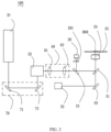
- FIG 1 is a coherent anti-Stokes Raman scattering microscope imaging device 100 according to an embodiment useful for understanding the invention, which is used to obtain microscopic image information of a sample 800.
- the coherent anti-Stokes Raman scattering microscope imaging device 100 includes a laser light source 21, a two-dimensional galvanometer assembly 22, a first dichroic mirror 23, an objective lens 24, a sample translation platform 25, a collector 26, and a data processing module.
- the laser light source 21 is configured to generate a first laser beam and a second laser beam.
- the first laser beam and the second laser beam are output collinearly.
- the first laser beam is used as a pump light
- the second laser beam is used as a Stokes light.
- the first laser beam and the second laser beam are incident on the two-dimensional galvanometer assembly 22, and the two-dimensional galvanometer assembly 22 adjusts optical paths of the first laser beam and the second laser beam.
- the first laser beam and the second laser beam leaving the two-dimensional galvanometer assembly 22 pass through the first dichroic mirror 23 and the objective lens 24 successively.
- the first laser beam and the second laser beam transmit through the first dichroic mirror 23.
- the objective lens 24 focuses the first laser beam and the second laser beam onto the sample translation platform 25.
- the sample 800 on the sample translation platform 25 generates a signal light under the action of the first laser beam and the second laser beam.
- the first dichroic mirror 23 reflects the signal light to the collector 26, the collector 26 generates initial data according to the signal light, and the initial data is output to the data processing module.
- the first laser beam and the second laser beam are generated via the laser light source 21.
- the first laser beam and the second laser beam are output collinearly, and the first laser beam is used as the pump light, the second laser beam is used as Stokes light, which simplifies the optical path structure between the laser and the objective lens 24, avoids the need to split light and adjust the wavelength for the single-wavelength laser beam output by the laser, thereby facilitating the improvement of the compactness of the coherent anti-Stokes Raman scattering microscope imaging device 100 and reduced the volume, which are conducive to commercial development.
- the coherent anti-Stokes Raman scattering microscope imaging device 100 in order to accurately focus the first laser beam and the second laser beam on the sample 800 on the sample translation platform 25 through the objective lens 24, the coherent anti-Stokes Raman scattering microscope imaging device 100 also includes an automatic focusing mechanism.
- the automatic focusing mechanism includes a focus detection unit 32, a second dichroic mirror 31, and a moving assembly.
- the second dichroic mirror 31 is arranged in correspondence with the first dichroic mirror 23 and the objective lens 24, respectively.
- the first laser beam and the second laser beam are reflected to the objective lens 24 through the second dichroic mirror 31 after passing through the first dichroic mirror 23.
- the signal light is reflected to the first dichroic mirror 23 through the second dichroic mirror 31 after passing through the objective lens 24.
- the focus detection unit 32 generates a third laser beam.
- the third laser beam transmits the second dichroic mirror 31, and the third laser beam is parallel or collinear with the first laser beam and the second laser beam after transmitting through the second dichroic mirror 31.
- the third laser beam is focused on the sample translation platform 25 through the objective lens 24, and the third laser beam generates a reflected light on the sample translation platform 25.
- the reflected light returns to the focus detection unit 32 along the original path of the third laser beam.
- the focus detection unit 32 detects the reflected light.
- the objective lens 24 is mounted on the moving assembly.
- the moving assembly moves the objective lens 24 according to a detection result of the focus detection unit 32 to adjust the distance between the objective lens 24 and the sample translation platform 25.
- the reflected light is formed by the third laser beam reflected on the surface of the sample 800.
- the third laser beam has a good focusing effect on the sample 800.
- the focus detection unit 32 can generate the detection result according to the intensity of the reflected light or the image clarity, etc.
- the second dichroic mirror 31 is arranged in correspondence with the first dichroic mirror 23 and the objective lens 24, respectively, and the automatic focusing mechanism adjusts the position of the objective lens 24 before the laser light source 21 emits the first laser beam and the second laser beam, thereby realizing the coexistence of automatic focusing and anti-Stokes signal light, shortening the data collecting time, and benefiting the detection of large-area samples 800, the use process is simple and time-saving, which is convenient for the operator to use. Further, the objective lens 24 can be remotely programmed and controlled.
- the automatic focusing mechanism further includes a first reflector 33, which is arranged in correspondence with the second dichroic mirror 31 and the focus detection unit 32, respectively.
- the third laser beam and the reflected light are reflected on the first reflector 33; thus, the position of the focus detection unit 32 can be adjusted to improve the overall compactness of the coherent anti-Stokes Raman scattering microscope imaging device 100.
- the first convex lens 42 and the third dichroic mirror 44 are located between the focus detection unit 32 and the first reflector 33, and a reference light that passes through the objective lens 24 is reflected to the first convex lens 42 through the first reflector 33.
- the first reflector 33 in order to improve the reflection effect of the first reflector 33 on the third laser beam, the reflected light or the reference light, the first reflector 33 is plated with gold or silver. In order to further improve the reflection ability of the first reflector 33, the first reflector 33 is also plated with a special dielectric film.
- the coherent anti-Stokes Raman scattering microscope imaging device 100 further includes a narrow-band dichroic mirror 261 arranged between the first dichroic mirror 23 and the collector 26.
- the signal light transmits the narrow-band dichroic mirror 261 and enters the collector 26.
- the narrow-band dichroic mirror 261 absorbs or reflects the first laser beam and the second laser beam, thereby avoiding the first laser beam and the second laser beam affect the sampling of the collector 26 and improves the quality of the initial data output.
- the narrow-band dichroic mirror 261 is plated with a dielectric film to achieve high transmittance of signal light, and low transmittance of the pump light and the Stokes light.
- the OD of the narrow-band dichroic mirror 261 is between 6 and 8.
- the coherent anti-Stokes Raman scattering microscope imaging device 100 further includes a 4F system 60 located between the two-dimensional galvanometer assembly 22 and the first dichroic mirror 23.
- the output spot of the laser light source 21 is amplified via the 4F system 60, such that the size of the output spot of the laser light source 21 matches the aperture of the objective lens 24, such that the spot size obtained by focusing via the objective lens 24 has an appropriate size to improve the microscopic effect of the coherent anti-Stokes Raman scattering microscope imaging device 100.
- the 4F system 60 includes at least two convex lenses to achieve the expansion of the first laser beam and the second laser beam and projection thereof to the objective lens 24.
- the 4F system 60 includes a second convex lens 61 and a third convex lens 62.
- the focal length of the second convex lens 61 is smaller than the focal length of the third convex lens 62.
- the distance between the second convex lens 61 and the third convex lens 62 should be the sum of the focal lengths thereof.
- the coherent anti-Stokes Raman scattering microscope imaging device 100 further includes an adjustment assembly 70. After the first laser beam and the second laser beam are emitted from the laser light source 21, the first laser beam and the second laser beam are reflected to the two-dimensional galvanometer assembly 22 through the adjustment assembly 70.
- the adjustment assembly 70 in order to make the first laser beam and the second laser beam enter the two-dimensional galvanometer assembly 22 at a predetermined angle, the adjustment assembly 70 includes a second reflector 71 and a third reflector 72. The first laser beam and the second laser beam are reflected to the two-dimensional galvanometer assembly 22 through the second reflector 71 and the third reflector 72 successively.
- the reflection points of the first laser beam and the second laser beam on the third reflector 72 can be adjusted via adjusting the angle of the second reflector 71, and the angle of the first laser beam and the second laser beam entering the two-dimensional galvanometer assembly 22 can be adjusted by adjusting the angle of the third reflector 72.
- the surfaces of the second reflector 71 and the third reflector 72 are plated with a dielectric film to improve the reflectivity of the first laser beam and the second laser beam .
- the coherent anti-Stokes Raman scattering microscope imaging device 100 further includes a manual focusing assembly.
- the manual focusing assembly includes an indicating light source 41, a first convex lens 42, and a CCD camera 43.
- the indicating light source 41 is arranged on one side of the sample translation platform 25.
- the indicating light source 41 generates the reference light, and the reference light passes through the objective lens 24 and the second dichroic mirror 31.
- the first convex lens 42 focuses the reference light to enter the CCD camera 43.
- the CCD camera 43 When manually adjusting the focus, the CCD camera 43 obtains the image of the sample 800 on the sample translation platform 25 according to the reference light, and the debugging personnel determines whether the manual focus adjustment is accurate according to the sharpness of the image of the sample 800; specifically, the indicating light source 41 is a white light LED device.
- the focal length and installation position of the first convex lens 42 match the size of the sensing unit of the CCD camera 43. Specifically, the size and resolution of the sensing unit of the CCD camera 43 arranged in correspondence with the resolution of the objective lens 24.
- the manual focusing assembly further includes a third dichroic mirror 44.
- the first convex lens 42 and the third dichroic mirror 44 are located on the optical path of the third laser beam, the third dichroic mirror 44 is located between the focus detection unit 32 and the first convex lens 42.
- the third laser beam and the reflected light transmit through the third dichroic mirror 44, respectively.
- the third dichroic mirror 44 reflects the reference light, and causes the reference light to enter the CCD camera 43, such that the optical paths of the third laser beam, such that the third laser beam, the reflected light, and the reference light overlap.
- the coherent anti-Stokes Raman scattering microscope imaging device 100 further includes a main housing.
- the laser light source 21, the two-dimensional galvanometer assembly 22, the first dichroic mirror 23, the objective lens 24, the sample translation platform 25, the collector 26, the data processing module, the automatic focusing mechanism, and the manual focusing assembly are installed in the main housing; thus, effective protection is provided for important assemblies or mechanisms.
- the laser light source 21 is a femtosecond pulsed fiber laser or a picosecond pulsed fiber laser.
- the laser light source 21 is a Dual Color laser from Refined Laser Company, Germany.
- the first laser beam and the second laser beam are output synchronously in time and space; in this embodiment, the first laser beam is also used as probe light.
- the laser light source 21 outputs the first laser beam of 800 nm as the pump light and the second laser beam of 1040 nm as the Stokes light, and the obtained signal light has a wavelength of 652 nm.
- This embodiment can realize the detection and imaging of substances containing C-H chemical bonds.
- the laser light source 21 can output the first laser beam with an adjustable wavelength of 780-900 nm as the pump light, and output the second laser beam with a wavelength of 1040 nm as the Stokes light. This embodiment can achieve detection and imaging of substances containing C-H and C-D chemical bonds.
- the laser light source 21 can output a second laser beam with an adjustable wavelength of 930-1030 nm as the Stokes light, and output a first laser beam with a wavelength of 780 nm as the pump light.
- This embodiment can achieve detection and imaging of substances containing C-H and C-D chemical bonds.
- the first dichroic mirror 23 and the third dichroic mirror 44 are long-wave dichroic mirrors, and the surface of the first dichroic mirror 23 is plated with a dielectric film to achieve high transmittance of the long-wavelength and reflection of the short-wavelength, so as to ensure that the pump light and Stokes light can pass through, and the anti-Stokes signal light can be reflected.
- the second dichroic mirror 31 is a short-wave dichroic mirror, and the surface of the second dichroic mirror 31 is plated with a dielectric film to achieve the reflection of the first laser beam, the second laser beam and the signal light, while realizing the passage of the third laser beam, the reflected light and, in an embodiment, the reference light.
- the wavelength distribution of the third laser beam matches the second dichroic mirror 31 and the third dichroic mirror 44.
- the sample 800 is placed on the sample translation platform 25.
- the sample 800 can be moved to a scanning range of the two-dimensional galvanometer assembly 22 by the movement of the sample translation platform 25, and the scanning range of the sample translation platform 25 can be adjusted according to the size of the sample 800 and actual application requirements. Further, the sample translation platform 25 can be remotely programmed and controlled.
- the size of the mirror surface of the two-dimensional galvanometer assembly 22 should be larger than the spot size of the laser light source 21, and the scanning angle can be adjusted according to the scanning range of the sample 800.
- the two-dimensional galvanometer assembly 22 adjusts the optical paths of the first laser beam and the second laser beam, such that the first laser beam and the second laser beam can be transmitted to different parts within the scanning range of the surface of the sample 800.
- the collector 26 generates initial data corresponding to different parts of the sample after each adjustment of the two-dimensional scanning assembly 800.
- the collector 26 is a photomultiplier tube, and has the function of oversaturation shutdown, manual opening and remote opening; the data processing module integrates the initial data collected by the collector 26 into complete image information, in this embodiment, the data processing module is a computer.
- the first laser beam and the second laser beam are generated via the laser light source, the first laser beam and the second laser beam are output collinearly, and the first laser beam is used as the pump light, the second laser beam is used as Stokes light, which simplifies the optical path structure between the laser and the objective lens, avoids the need to split light and adjust the wavelength for the single-wavelength laser beam output by the laser, thereby facilitating the improvement of the compactness of the coherent anti-Stokes Raman scattering microscope imaging device and reduced the volume, which are conducive to commercial development.
Landscapes
- Physics & Mathematics (AREA)
- Spectroscopy & Molecular Physics (AREA)
- General Physics & Mathematics (AREA)
- Analytical Chemistry (AREA)
- Chemical & Material Sciences (AREA)
- Optics & Photonics (AREA)
- Health & Medical Sciences (AREA)
- Biochemistry (AREA)
- Life Sciences & Earth Sciences (AREA)
- General Health & Medical Sciences (AREA)
- Immunology (AREA)
- Pathology (AREA)
- Nuclear Medicine, Radiotherapy & Molecular Imaging (AREA)
- Engineering & Computer Science (AREA)
- Computer Vision & Pattern Recognition (AREA)
- General Engineering & Computer Science (AREA)
- Investigating, Analyzing Materials By Fluorescence Or Luminescence (AREA)
- Microscoopes, Condenser (AREA)
- Lens Barrels (AREA)
Claims (9)
- Bildgebungsvorrichtung (100) mit einem Mikroskop mit kohärenter Anti-Stokes-Raman-Streuung, umfassend: eine Laserlichtquelle (21), eine zweidimensionale Galvanometeranordnung (22), einen ersten dichroitischen Spiegel (23), eine Objektivlinse (24), eine Probentranslationsplattform (25), einen Kollektor (26) und ein Datenverarbeitungsmodul; wobei die Laserlichtquelle (21) konfiguriert ist, um einen ersten Laserstrahl und einen zweiten Laserstrahl zu erzeugen; der erste Laserstrahl und der zweite Laserstrahl kollinear ausgegeben werden; der erste Laserstrahl und der zweite Laserstrahl auf die zweidimensionale Galvanometeranordnung (22) einfallen, die zweidimensionale Galvanometeranordnung (22) optische Pfade des ersten Laserstrahls und des zweiten Laserstrahls einstellt; der erste Laserstrahl und der zweite Laserstrahl, die die zweidimensionale Galvanometeranordnung (22) verlassen, nacheinander durch den ersten dichroitischen Spiegel (23) und die Objektivlinse (24) hindurchgehen; die Objektivlinse (24) den ersten Laserstrahl und den zweiten Laserstrahl auf die Probentranslationsplattform (25) fokussiert; ein Signallicht, das durch die Probentranslationsplattform (25) erzeugt wird, durch die Objektivlinse (24) hindurchgeht, der erste dichroitische Spiegel (23) das Signallicht zu dem Kollektor (26) reflektiert und der Kollektor (26) Anfangsdaten gemäß dem Signallicht erzeugt und die Anfangsdaten an das Datenverarbeitungsmodul ausgibt;
dadurch gekennzeichnet, dassdie Bildgebungsvorrichtung (100) mit einem Mikroskop mit kohärenter Anti-Stokes-Raman-Streuung ferner einen automatischen Fokussiermechanismus umfasst, wobei der automatische Fokussiermechanismus eine Fokusdetektionseinheit (32), einen zweiten dichroitischen Spiegel (31) und eine Bewegungsanordnung umfasst; der zweite dichroitische Spiegel (31) in Übereinstimmung mit dem ersten dichroitischen Spiegel (23) bzw. der Objektivlinse (24) angeordnet ist; der erste Laserstrahl und der zweite Laserstrahl durch den zweiten dichroitischen Spiegel (31) zu der Objektivlinse (24) reflektiert werden, nachdem sie durch den ersten dichroitischen Spiegel (23) hindurchgegangen sind; das Signallicht durch den zweiten dichroitischen Spiegel (31) zu dem ersten dichroitischen Spiegel (23) reflektiert wird, nachdem es durch die Objektivlinse (24) hindurchgegangen ist; die Fokusdetektionseinheit (32) einen dritten Laserstrahl erzeugt, der durch den zweiten dichroitischen Spiegel (31) hindurchgeht; der dritte Laserstrahl durch die Objektivlinse (24) auf die Probentranslationsplattform (25) fokussiert wird und der dritte Laserstrahl ein reflektiertes Licht auf der Probentranslationsplattform (25) erzeugt; das reflektierte Licht zu der Fokusdetektionseinheit (32) entlang eines ursprünglichen Pfads des dritten Laserstrahls zurückkehrt; die Fokusdetektionseinheit (32) das reflektierte Licht detektiert; die Objektivlinse (24) auf der Bewegungsanordnung montiert ist; die Bewegungsanordnung die Objektivlinse gemäß einem Detektionsergebnis der Fokusdetektionseinheit (32) bewegt;wobei der zweite dichroitische Spiegel (31) ein kurzwelliger dichroitischer Spiegel ist und die Oberfläche des zweiten dichroitischen Spiegels (31) mit einem dielektrischen Film plattiert ist, um eine Reflexion des ersten Laserstrahls, des zweiten Laserstrahls und des Signallichts zu erreichen, während der Durchgang des dritten Laserstrahls und des reflektierten Lichts realisiert wird. - Bildgebungsvorrichtung (100) mit einem Mikroskop mit kohärenter Anti-Stokes-Raman-Streuung nach Anspruch 1, ferner umfassend eine manuelle Fokussieranordnung, wobei die manuelle Fokussieranordnung eine Anzeigelichtquelle (41), eine erste konvexe Linse (42) und eine CCD-Kamera (43) umfasst; die Anzeigelichtquelle (41) auf einer Seite der Probentranslationsplattform (25) angeordnet ist; die Anzeigelichtquelle (41) ein Referenzlicht erzeugt, das durch die Objektivlinse (24) und den zweiten dichroitischen Spiegel (31) hindurchgeht; die erste konvexe Linse (42) das Referenzlicht in die CCD-Kamera (43) fokussiert.
- Bildgebungsvorrichtung (100) mit einem Mikroskop mit kohärenter Anti-Stokes-Raman-Streuung nach Anspruch 2, ferner umfassend ein Hauptgehäuse; wobei die Laserlichtquelle (21), die zweidimensionale Galvanometeranordnung (22), der erste dichroitische Spiegel (23), die Objektivlinse (24), die Probentranslationsplattform (25), der Kollektor (26), der automatische Fokussiermechanismus und die manuelle Fokussieranordnung in dem Hauptgehäuse installiert sind.
- Bildgebungsvorrichtung (100) mit einem Mikroskop mit kohärenter Anti-Stokes-Raman-Streuung nach Anspruch 1, wobei der automatische Fokussiermechanismus ferner einen ersten Reflektor (33) umfasst, der erste Reflektor (33) in Übereinstimmung mit dem zweiten dichroitischen Spiegel (31) bzw. der Fokusdetektionseinheit (32) angeordnet ist und der dritte Laserstrahl und das reflektierte Licht auf dem ersten Reflektor (33) reflektiert werden.
- Bildgebungsvorrichtung (100) mit einem Mikroskop mit kohärenter Anti-Stokes-Raman-Streuung nach Anspruch 4, wobei der erste Reflektor (33) mit Gold oder Silber plattiert ist.
- Bildgebungsvorrichtung (100) mit einem Mikroskop mit kohärenter Anti-Stokes-Raman-Streuung nach Anspruch 1, ferner umfassend einen schmalbandigen dichroitischen Spiegel (261), der zwischen dem ersten dichroitischen Spiegel (23) und dem Kollektor (26) angeordnet ist, wobei das Signallicht den schmalbandigen dichroitischen Spiegel (261) durchlässt und in den Kollektor (26) eintritt; der schmalbandige dichroitische Spiegel (261) den ersten Laserstrahl und den zweiten Laserstrahl absorbiert oder reflektiert.
- Bildgebungsvorrichtung (100) mit einem Mikroskop mit kohärenter Anti-Stokes-Raman-Streuung nach einem der Ansprüche 1 bis 6, ferner umfassend ein 4F-System (60), das sich zwischen der zweidimensionalen Galvanometeranordnung (22) und dem ersten dichroitischen Spiegel (23) befindet.
- Bildgebungsvorrichtung (100) mit einem Mikroskop mit kohärenter Anti-Stokes-Raman-Streuung nach einem der Ansprüche 1 bis 6, ferner umfassend eine Einstellanordnung (70), wobei, nachdem der erste Laserstrahl und der zweite Laserstrahl von der Laserlichtquelle (21) emittiert werden, der erste Laserstrahl und der zweite Laserstrahl durch die Einstellanordnung (70) zu der zweidimensionalen Galvanometeranordnung (22) reflektiert werden.
- Bildgebungsvorrichtung (100) mit einem Mikroskop mit kohärenter Anti-Stokes-Raman-Streuung nach Anspruch 8, wobei die Einstellanordnung (70) einen zweiten Reflektor (71) und einen dritten Reflektor (72) umfasst, der erste Laserstrahl und der zweite Laserstrahl nacheinander durch den zweiten Reflektor (71) und den dritten Reflektor (72) zu der zweidimensionalen Galvanometeranordnung (22) reflektiert werden.
Applications Claiming Priority (2)
| Application Number | Priority Date | Filing Date | Title |
|---|---|---|---|
| CN201910236685.2A CN109765213B (zh) | 2019-03-27 | 2019-03-27 | 相干反斯托克斯拉曼散射显微镜成像装置 |
| PCT/CN2019/120051 WO2020192153A1 (zh) | 2019-03-27 | 2019-11-21 | 相干反斯托克斯拉曼散射显微镜成像装置 |
Publications (4)
| Publication Number | Publication Date |
|---|---|
| EP3940372A1 EP3940372A1 (de) | 2022-01-19 |
| EP3940372A4 EP3940372A4 (de) | 2022-11-09 |
| EP3940372B1 true EP3940372B1 (de) | 2025-03-26 |
| EP3940372C0 EP3940372C0 (de) | 2025-03-26 |
Family
ID=66459813
Family Applications (1)
| Application Number | Title | Priority Date | Filing Date |
|---|---|---|---|
| EP19921372.9A Active EP3940372B1 (de) | 2019-03-27 | 2019-11-21 | Bildgebungsvorrichtung mit kohärentem anti-stokes-raman-streuungs-mikroskop |
Country Status (6)
| Country | Link |
|---|---|
| US (1) | US11879780B2 (de) |
| EP (1) | EP3940372B1 (de) |
| JP (1) | JP7203464B2 (de) |
| CN (1) | CN109765213B (de) |
| ES (1) | ES3018587T3 (de) |
| WO (1) | WO2020192153A1 (de) |
Families Citing this family (10)
| Publication number | Priority date | Publication date | Assignee | Title |
|---|---|---|---|---|
| CN109765213B (zh) * | 2019-03-27 | 2024-03-29 | 苏州威邦震电光电技术有限公司 | 相干反斯托克斯拉曼散射显微镜成像装置 |
| CN110579462B (zh) * | 2019-09-18 | 2020-07-10 | 华中科技大学 | 一种基于高重频飞秒激光的时间分辨宽谱cars光谱成像装置 |
| CN111735770A (zh) * | 2020-08-07 | 2020-10-02 | 北京卓立汉光仪器有限公司 | 光谱成像装置和方法 |
| CN112649415B (zh) * | 2020-12-11 | 2022-04-22 | 华南理工大学 | 三光束自同步高速扫频光纤激光拉曼扫描成像系统及方法 |
| CN113252638B (zh) * | 2021-05-13 | 2023-04-28 | 中国工程物理研究院流体物理研究所 | 基于4f光学系统的fs-CARS平面成像装置 |
| EP4277166A1 (de) * | 2022-05-13 | 2023-11-15 | British Telecommunications public limited company | Detektor für elektromagnetische felder |
| CN115420729B (zh) * | 2022-11-02 | 2023-06-23 | 中国科学院新疆理化技术研究所 | 基于多步激发244nm激光增强拉曼效应的方法 |
| CN119518408A (zh) * | 2024-10-29 | 2025-02-25 | 北京航空航天大学 | 一种相干拉曼散射显微镜的背景信号抑制系统 |
| CN120908101B (zh) * | 2025-10-10 | 2026-01-23 | 吉林大学 | 一种基于飞秒激光和拉曼光谱分析的肺癌快速检测系统 |
| CN121410094B (zh) * | 2025-12-30 | 2026-03-03 | 上海凯来仪器有限公司 | 一种cars-la-icp-ms联用的多模分析系统及分析方法 |
Family Cites Families (31)
| Publication number | Priority date | Publication date | Assignee | Title |
|---|---|---|---|---|
| US5170204A (en) * | 1988-09-16 | 1992-12-08 | Minolta Camera Kabushiki Kaisha | Display system for displaying information in the viewfinder of a camera |
| DE19916749B4 (de) * | 1999-04-14 | 2004-02-12 | Carl Zeiss Jena Gmbh | Verfahren zur Untersuchung von Proben |
| ATE543080T1 (de) * | 2000-07-13 | 2012-02-15 | Harvard College | System und verfahren für die epidetektions- kohärenz-anti-stokes-raman-streumikroskopie |
| JP2005062515A (ja) * | 2003-08-13 | 2005-03-10 | Nikon Corp | 蛍光顕微鏡 |
| TWI348408B (en) * | 2004-04-28 | 2011-09-11 | Olympus Corp | Laser processing device |
| JP4785480B2 (ja) * | 2005-09-22 | 2011-10-05 | 三鷹光器株式会社 | 光学計測システム |
| US7502106B2 (en) * | 2006-09-21 | 2009-03-10 | Honeywell International Inc. | SERS analyzer |
| US20110001963A1 (en) | 2009-07-02 | 2011-01-06 | Durack Gary P | System and method for the measurement of multiple emissions from multiple parallel flow channels in a flow cytometry system |
| CN102116929B (zh) * | 2011-01-30 | 2013-03-27 | 中国科学院西安光学精密机械研究所 | 高速宽视场相干反斯托克斯拉曼散射显微系统及方法 |
| KR101799518B1 (ko) * | 2011-05-03 | 2017-11-21 | 삼성전자 주식회사 | 형광 검출 광학계 및 이를 포함하는 다채널 형광 검출 장치 |
| DE102011084562B4 (de) * | 2011-10-14 | 2018-02-15 | Leica Microsystems Cms Gmbh | Verfahren und Vorrichtung zur Feststellung und Korrektur von sphärischen Abbildungsfehlern in einem mikroskopischen Abbildungsstrahlengang |
| CN103219638B (zh) * | 2013-03-18 | 2016-02-03 | 深圳大学 | 一种超连续谱光源及相干反斯托克斯拉曼散射成像系统 |
| FR3020141B1 (fr) * | 2014-04-17 | 2018-01-05 | Horiba Jobin Yvon Sas | Appareil et procede de microscopie a balayage de faisceau optique |
| CN104316506B (zh) * | 2014-10-14 | 2017-05-10 | 上海交通大学 | 拉曼探头和可自动对焦的拉曼信号探测系统以及方法 |
| CN104330398B (zh) * | 2014-11-20 | 2017-03-29 | 福建师范大学 | 一种多模式非线性光学显微成像方法及装置 |
| US9772540B2 (en) | 2015-07-09 | 2017-09-26 | Bio-Tek Instruments, Inc. | Autofocus for imaging system |
| CN105241853B (zh) * | 2015-09-07 | 2019-05-07 | 深圳市瀚海基因生物科技有限公司 | 一种全内反射荧光成像系统 |
| CN205246540U (zh) * | 2015-12-01 | 2016-05-18 | 中国科学院上海技术物理研究所 | 双重复用激光光谱火星矿物成分分析系统 |
| CN106546334A (zh) * | 2016-11-03 | 2017-03-29 | 北京信息科技大学 | 空间自调焦激光共焦拉曼光谱探测方法与装置 |
| JP2018120006A (ja) * | 2017-01-23 | 2018-08-02 | オリンパス株式会社 | 超解像顕微鏡 |
| JP7006010B2 (ja) * | 2017-08-16 | 2022-01-24 | 株式会社ニコン | 顕微鏡 |
| JP2019045396A (ja) * | 2017-09-05 | 2019-03-22 | 学校法人早稲田大学 | ラマン分光測定装置及びラマン分光測定方法 |
| JP7752942B2 (ja) * | 2017-09-08 | 2025-10-14 | パデュー リサーチ ファウンデイション | 誘導ラマン代謝イメージングによる抗生物質感受性の判定方法 |
| CN109030454A (zh) * | 2018-07-19 | 2018-12-18 | 温州森佰生物科技有限公司 | 一种高分辨生物检测成像方法 |
| CN108747057B (zh) * | 2018-08-02 | 2023-05-05 | 华侨大学 | 应用于激光切割装置的随动光路传输系统 |
| CN108964781A (zh) * | 2018-08-13 | 2018-12-07 | 广州光智科技有限公司 | 多通道相干拉曼散射光学装置和成像系统 |
| CN108827940B (zh) * | 2018-08-20 | 2023-09-19 | 吉林大学 | 一种三维激光拉曼散射光谱测量系统 |
| CN108971747B (zh) * | 2018-08-29 | 2020-07-28 | 华中科技大学 | 一种具备在线监测功能的超快激光微纳加工装置 |
| CN109444106B (zh) * | 2018-11-14 | 2019-11-26 | 东莞理工学院 | 一种基于表面增强拉曼光谱的光催化原位监测系统 |
| CN209707380U (zh) * | 2019-03-27 | 2019-11-29 | 威朋(苏州)医疗器械有限公司 | 相干反斯托克斯拉曼散射显微镜成像装置 |
| CN109765213B (zh) * | 2019-03-27 | 2024-03-29 | 苏州威邦震电光电技术有限公司 | 相干反斯托克斯拉曼散射显微镜成像装置 |
-
2019
- 2019-03-27 CN CN201910236685.2A patent/CN109765213B/zh active Active
- 2019-11-21 EP EP19921372.9A patent/EP3940372B1/de active Active
- 2019-11-21 WO PCT/CN2019/120051 patent/WO2020192153A1/zh not_active Ceased
- 2019-11-21 ES ES19921372T patent/ES3018587T3/es active Active
- 2019-11-21 JP JP2021560308A patent/JP7203464B2/ja active Active
- 2019-11-21 US US17/598,211 patent/US11879780B2/en active Active
Also Published As
| Publication number | Publication date |
|---|---|
| EP3940372A4 (de) | 2022-11-09 |
| US11879780B2 (en) | 2024-01-23 |
| EP3940372A1 (de) | 2022-01-19 |
| US20220178750A1 (en) | 2022-06-09 |
| EP3940372C0 (de) | 2025-03-26 |
| CN109765213A (zh) | 2019-05-17 |
| ES3018587T3 (es) | 2025-05-16 |
| WO2020192153A1 (zh) | 2020-10-01 |
| CN109765213B (zh) | 2024-03-29 |
| JP2022528951A (ja) | 2022-06-16 |
| JP7203464B2 (ja) | 2023-01-13 |
Similar Documents
| Publication | Publication Date | Title |
|---|---|---|
| US11879780B2 (en) | Coherent anti-Stokes Raman scattering microscope imaging apparatus | |
| CN103743718B (zh) | 共聚焦显微拉曼和激光诱导击穿光谱联用激光光谱分析仪 | |
| CN115046933B (zh) | 微区圆二色谱及圆偏振发光的测试装置 | |
| CN113484293A (zh) | 基于单光子计数法的显微圆偏振荧光光谱探测系统及方法 | |
| CN110987900A (zh) | 基于光电倍增管的高灵敏度拉曼光谱仪 | |
| CN211652548U (zh) | 基于光电倍增管的高灵敏度拉曼光谱仪 | |
| CN108919472B (zh) | 一种多分光镜式高灵敏度同轴光学镜筒 | |
| CN213275352U (zh) | 一种基于离轴抛物面反射镜的拉曼信号收集探头 | |
| CN111474164B (zh) | 显微激光拉曼光谱仪及其工作方法 | |
| CN113359287A (zh) | 可调节角度的旋转物镜及显微镜 | |
| CN107356581B (zh) | 全深度远端扫描的拉曼光谱仪 | |
| CN217132938U (zh) | 一种显微线偏振荧光光谱成像测量系统 | |
| CN116380867A (zh) | 一种拉曼/荧光双光路光谱检测装置及检测方法 | |
| CN110208240A (zh) | 基于时间域频率域压制杂散光的太赫兹拉曼光谱检测装置 | |
| CN215493172U (zh) | 基于单光子计数法的显微圆偏振荧光光谱探测系统 | |
| CN206440616U (zh) | 一种用于激光探针成分分析仪的光路系统 | |
| CN216160473U (zh) | 一种小型多功能激光成分分析仪 | |
| CN106645097A (zh) | 一种用于激光探针成分分析仪的光路系统 | |
| RU2515341C2 (ru) | Двухфотонный сканирующий микроскоп с автоматической точной фокусировкой изображения и способ автоматической точной фокусировки изображения | |
| CN118983685B (zh) | 一种x射线自由电子激光和飞秒激光的时空耦合系统及方法 | |
| CN115493695A (zh) | 微区瞬态吸收光谱测量系统 | |
| US10474002B2 (en) | Generation of high energy mid-infrared continuum laser pulses | |
| CN112014362A (zh) | 显微成像全谱段高压模块时间分辨荧光测量系统 | |
| CN211785622U (zh) | 太赫兹近场显微镜的太赫兹脉冲束引出机构 | |
| CN118483211B (zh) | 基于级联光谱仪的拉曼光谱测试系统及其测试方法 |
Legal Events
| Date | Code | Title | Description |
|---|---|---|---|
| STAA | Information on the status of an ep patent application or granted ep patent |
Free format text: STATUS: THE INTERNATIONAL PUBLICATION HAS BEEN MADE |
|
| PUAI | Public reference made under article 153(3) epc to a published international application that has entered the european phase |
Free format text: ORIGINAL CODE: 0009012 |
|
| STAA | Information on the status of an ep patent application or granted ep patent |
Free format text: STATUS: REQUEST FOR EXAMINATION WAS MADE |
|
| 17P | Request for examination filed |
Effective date: 20211011 |
|
| AK | Designated contracting states |
Kind code of ref document: A1 Designated state(s): AL AT BE BG CH CY CZ DE DK EE ES FI FR GB GR HR HU IE IS IT LI LT LU LV MC MK MT NL NO PL PT RO RS SE SI SK SM TR |
|
| DAV | Request for validation of the european patent (deleted) | ||
| DAX | Request for extension of the european patent (deleted) | ||
| A4 | Supplementary search report drawn up and despatched |
Effective date: 20221007 |
|
| RIC1 | Information provided on ipc code assigned before grant |
Ipc: G01N 21/65 20060101AFI20220930BHEP |
|
| GRAP | Despatch of communication of intention to grant a patent |
Free format text: ORIGINAL CODE: EPIDOSNIGR1 |
|
| STAA | Information on the status of an ep patent application or granted ep patent |
Free format text: STATUS: GRANT OF PATENT IS INTENDED |
|
| INTG | Intention to grant announced |
Effective date: 20241014 |
|
| GRAS | Grant fee paid |
Free format text: ORIGINAL CODE: EPIDOSNIGR3 |
|
| GRAA | (expected) grant |
Free format text: ORIGINAL CODE: 0009210 |
|
| STAA | Information on the status of an ep patent application or granted ep patent |
Free format text: STATUS: THE PATENT HAS BEEN GRANTED |
|
| AK | Designated contracting states |
Kind code of ref document: B1 Designated state(s): AL AT BE BG CH CY CZ DE DK EE ES FI FR GB GR HR HU IE IS IT LI LT LU LV MC MK MT NL NO PL PT RO RS SE SI SK SM TR |
|
| REG | Reference to a national code |
Ref country code: GB Ref legal event code: FG4D |
|
| REG | Reference to a national code |
Ref country code: CH Ref legal event code: EP |
|
| REG | Reference to a national code |
Ref country code: DE Ref legal event code: R096 Ref document number: 602019067946 Country of ref document: DE |
|
| REG | Reference to a national code |
Ref country code: IE Ref legal event code: FG4D |
|
| U01 | Request for unitary effect filed |
Effective date: 20250326 |
|
| U07 | Unitary effect registered |
Designated state(s): AT BE BG DE DK EE FI FR IT LT LU LV MT NL PT RO SE SI Effective date: 20250401 |
|
| REG | Reference to a national code |
Ref country code: ES Ref legal event code: FG2A Ref document number: 3018587 Country of ref document: ES Kind code of ref document: T3 Effective date: 20250516 |
|
| PG25 | Lapsed in a contracting state [announced via postgrant information from national office to epo] |
Ref country code: RS Free format text: LAPSE BECAUSE OF FAILURE TO SUBMIT A TRANSLATION OF THE DESCRIPTION OR TO PAY THE FEE WITHIN THE PRESCRIBED TIME-LIMIT Effective date: 20250626 |
|
| PG25 | Lapsed in a contracting state [announced via postgrant information from national office to epo] |
Ref country code: NO Free format text: LAPSE BECAUSE OF FAILURE TO SUBMIT A TRANSLATION OF THE DESCRIPTION OR TO PAY THE FEE WITHIN THE PRESCRIBED TIME-LIMIT Effective date: 20250626 |
|
| PG25 | Lapsed in a contracting state [announced via postgrant information from national office to epo] |
Ref country code: HR Free format text: LAPSE BECAUSE OF FAILURE TO SUBMIT A TRANSLATION OF THE DESCRIPTION OR TO PAY THE FEE WITHIN THE PRESCRIBED TIME-LIMIT Effective date: 20250326 |
|
| PG25 | Lapsed in a contracting state [announced via postgrant information from national office to epo] |
Ref country code: GR Free format text: LAPSE BECAUSE OF FAILURE TO SUBMIT A TRANSLATION OF THE DESCRIPTION OR TO PAY THE FEE WITHIN THE PRESCRIBED TIME-LIMIT Effective date: 20250627 |
|
| PG25 | Lapsed in a contracting state [announced via postgrant information from national office to epo] |
Ref country code: SM Free format text: LAPSE BECAUSE OF FAILURE TO SUBMIT A TRANSLATION OF THE DESCRIPTION OR TO PAY THE FEE WITHIN THE PRESCRIBED TIME-LIMIT Effective date: 20250326 |
|
| PG25 | Lapsed in a contracting state [announced via postgrant information from national office to epo] |
Ref country code: PL Free format text: LAPSE BECAUSE OF FAILURE TO SUBMIT A TRANSLATION OF THE DESCRIPTION OR TO PAY THE FEE WITHIN THE PRESCRIBED TIME-LIMIT Effective date: 20250326 |
|
| PG25 | Lapsed in a contracting state [announced via postgrant information from national office to epo] |
Ref country code: SK Free format text: LAPSE BECAUSE OF FAILURE TO SUBMIT A TRANSLATION OF THE DESCRIPTION OR TO PAY THE FEE WITHIN THE PRESCRIBED TIME-LIMIT Effective date: 20250326 |
|
| PG25 | Lapsed in a contracting state [announced via postgrant information from national office to epo] |
Ref country code: IS Free format text: LAPSE BECAUSE OF FAILURE TO SUBMIT A TRANSLATION OF THE DESCRIPTION OR TO PAY THE FEE WITHIN THE PRESCRIBED TIME-LIMIT Effective date: 20250726 |
|
| U20 | Renewal fee for the european patent with unitary effect paid |
Year of fee payment: 7 Effective date: 20251124 |
|
| PGFP | Annual fee paid to national office [announced via postgrant information from national office to epo] |
Ref country code: GB Payment date: 20251124 Year of fee payment: 7 |
|
| PG25 | Lapsed in a contracting state [announced via postgrant information from national office to epo] |
Ref country code: CZ Free format text: LAPSE BECAUSE OF FAILURE TO SUBMIT A TRANSLATION OF THE DESCRIPTION OR TO PAY THE FEE WITHIN THE PRESCRIBED TIME-LIMIT Effective date: 20250326 |
|
| PGFP | Annual fee paid to national office [announced via postgrant information from national office to epo] |
Ref country code: ES Payment date: 20251229 Year of fee payment: 7 |
|
| PLBE | No opposition filed within time limit |
Free format text: ORIGINAL CODE: 0009261 |
|
| STAA | Information on the status of an ep patent application or granted ep patent |
Free format text: STATUS: NO OPPOSITION FILED WITHIN TIME LIMIT |
|
| REG | Reference to a national code |
Ref country code: CH Ref legal event code: L10 Free format text: ST27 STATUS EVENT CODE: U-0-0-L10-L00 (AS PROVIDED BY THE NATIONAL OFFICE) Effective date: 20260211 |
|
| 26N | No opposition filed |
Effective date: 20260105 |