EP4277166A1 - Detektor für elektromagnetische felder - Google Patents
Detektor für elektromagnetische felder Download PDFInfo
- Publication number
- EP4277166A1 EP4277166A1 EP22173349.6A EP22173349A EP4277166A1 EP 4277166 A1 EP4277166 A1 EP 4277166A1 EP 22173349 A EP22173349 A EP 22173349A EP 4277166 A1 EP4277166 A1 EP 4277166A1
- Authority
- EP
- European Patent Office
- Prior art keywords
- transmission medium
- photon
- frequency range
- excited state
- frequency
- Prior art date
- Legal status (The legal status is an assumption and is not a legal conclusion. Google has not performed a legal analysis and makes no representation as to the accuracy of the status listed.)
- Ceased
Links
Images


Classifications
-
- H—ELECTRICITY
- H04—ELECTRIC COMMUNICATION TECHNIQUE
- H04B—TRANSMISSION
- H04B10/00—Transmission systems employing electromagnetic waves other than radio-waves, e.g. infrared, visible or ultraviolet light, or employing corpuscular radiation, e.g. quantum communication
- H04B10/70—Photonic quantum communication
-
- G—PHYSICS
- G01—MEASURING; TESTING
- G01R—MEASURING ELECTRIC VARIABLES; MEASURING MAGNETIC VARIABLES
- G01R29/00—Arrangements for measuring or indicating electric quantities not covered by groups G01R19/00 - G01R27/00
- G01R29/08—Measuring electromagnetic field characteristics
- G01R29/0864—Measuring electromagnetic field characteristics characterised by constructional or functional features
- G01R29/0878—Sensors; antennas; probes; detectors
- G01R29/0885—Sensors; antennas; probes; detectors using optical probes, e.g. electro-optical, luminescent, glow discharge, or optical interferometers
-
- H—ELECTRICITY
- H04—ELECTRIC COMMUNICATION TECHNIQUE
- H04B—TRANSMISSION
- H04B10/00—Transmission systems employing electromagnetic waves other than radio-waves, e.g. infrared, visible or ultraviolet light, or employing corpuscular radiation, e.g. quantum communication
- H04B10/60—Receivers
-
- H—ELECTRICITY
- H04—ELECTRIC COMMUNICATION TECHNIQUE
- H04B—TRANSMISSION
- H04B2210/00—Indexing scheme relating to optical transmission systems
- H04B2210/006—Devices for generating or processing an RF signal by optical means
Definitions
- the present invention relates to a method for detecting an electromagnetic field, and a detector and system for detecting an electromagnetic field.
- a Rydberg atom is an atom with one or more electrons excited to a very high principal quantum number (e.g. >10). These Rydberg atoms have several useful properties, such as very large dipole moments and long decay periods.
- the Rydberg atom may be used to detect an electromagnetic field.
- a Rydberg-atom based electromagnetic field detector is based on the Electromagnetically Induced Transparency (EIT) effect.
- the EIT effect may be experienced when a probe laser and a coupling laser are used to elevate electrons of an atomic medium to a Rydberg state. In this state, the atomic medium becomes transparent to the probe laser.
- An electromagnetic field incident at the atomic medium may then cause a further transition of an electron from the Rydberg state to a further Rydberg state. Electrons may subsequently drop from the further Rydberg state to the ground state so that the atomic medium becomes less transparent to the probe laser. The electromagnetic field may therefore be detected from this change in transparency as a change in intensity of the probe laser.
- Rydberg-atom based electromagnetic receivers have also been shown to detect frequency modulated and phase modulated electromagnetic fields.
- Rydberg-atom based electromagnetic field detector utilises an interferometric technique in which the probe laser is split into a first and second path, in which the first path passes through the atomic medium and a second path does not pass through the atomic medium.
- a coupling laser also passes through the atomic medium to excite electrons to the Rydberg state.
- An incident electromagnetic field at the atomic medium causes a further transition of an electron from the Rydberg state to a further Rydberg state, which changes the refractive index of the atomic medium.
- the resultant change in optical path length difference between the first and second path is detectable as a change in intensity of the combined first and second paths of the probe signal.
- Detection of an incident electromagnetic field at the photodetector requires the change in intensity of the probe laser to be detectable above the background signal.
- a method of detecting a photon in a first frequency range comprising the steps of: exciting a first transmission medium by a first probe signal at a first probe frequency, wherein the first probe signal excites electrons of the first transmission medium from a ground state of the first transmission medium to a first excited state of the first transmission medium; exciting the first transmission medium by a first coupling signal at a first coupling frequency, wherein the first coupling signal overlaps with the first probe signal in the first transmission medium and excites electrons of the first transmission medium to a predetermined excited state of the first transmission medium such that a first photon in the first frequency range incident upon the first transmission medium excites an electron in the predetermined excited state of the first transmission medium to a further excited state of the first transmission medium, wherein a first photon in a second frequency range is emitted as part of a subsequent deexcitation of the electron from the further excited state of the first transmission medium; and detecting the first photon in the first frequency range by detecting
- the electron may be excited from the predetermined excited state of the first transmission medium to the further excited state of the first transmission medium when the first photon incident upon the transmission medium has a first polarisation
- the detection step may include detecting the first photon in the first frequency range and having the first polarisation by detecting the first photon in the second frequency range
- the method may further comprise the steps of: exciting a second transmission medium by a second probe signal at a second probe frequency, wherein the second probe signal excites electrons of the second transmission medium from a ground state of the second transmission medium to a first excited state of the second transmission medium; exciting the second transmission medium by a second coupling signal at a second coupling frequency, wherein the second coupling signal overlaps with the second probe signal in the second transmission medium and excites electrons of the second transmission medium to a predetermined excited state of the second transmission medium such that a second photon in the first frequency range incident upon the second transmission medium and having a second polarisation excites an electron in the predetermined excited state of the second transmission medium to a further excited
- the method may further comprise the steps of: demodulating data based on detection of the first photon in the first frequency range having the first polarisation corresponding to a first bit value, and detection of the second photon in the first frequency range having the second polarisation corresponding to a second bit value.
- the method may further comprise the step of: determining a cryptographic key based on the demodulated data.
- a device for detecting a photon in a first frequency range comprising: a first transmission medium excitable by a first probe signal at a first probe frequency and an overlapping first coupling signal at a first coupling frequency, wherein the first probe frequency excites electrons of the first transmission medium from a ground state of the first transmission medium to a first excited state of the first transmission medium and the first coupling frequency excites electrons of the first transmission medium to a predetermined excited state of the first transmission medium such that a first photon in a first frequency range incident upon the first transmission medium excites an electron in the predetermined excited state of the first transmission medium to a further excited state of the first transmission medium, wherein a first photon in a second frequency range is emitted as part of a subsequent deexcitation of the electron in the further excited state of the first transmission medium; and a first detector configured to detect the first photon in the first frequency range by detecting the first photon in the second frequency range.
- the device may further comprise: a housing configured to permit passage of the first photon in the first frequency range to the first transmission medium when arriving in a predetermined direction.
- the probe signal and coupling signal may have a first configuration such that the electron may be excited from the predetermined excited state of the first transmission medium to the further excited state of the first transmission medium when the first photon incident upon the transmission medium has a first polarisation
- the first detector may be configured to detect the first photon in the first frequency range and having the first polarisation by detecting the first photon in the second frequency range
- the detector may further comprise: a second transmission medium excitable by a second probe signal at a second probe frequency and an overlapping second coupling signal at a second coupling frequency, wherein the second probe frequency excites electrons of the second transmission medium from a ground state of the second transmission medium to a first excited state of the second transmission medium, wherein the second coupling frequency excites electrons of the second transmission medium to a predetermined excited state of the second transmission medium such that a second photon in the first frequency range having a second polarisation incident upon the second transmission medium excites an electron in the predetermined excited state of the second transmission medium to a further excited state of the second
- the device may further comprise: a processor configured to demodulate data based on detection of the first photon in the first frequency range having the first polarisation corresponding to a first bit value and detection of the second photon in the first frequency range having the second polarisation corresponding to a second bit value.
- a processor configured to demodulate data based on detection of the first photon in the first frequency range having the first polarisation corresponding to a first bit value and detection of the second photon in the first frequency range having the second polarisation corresponding to a second bit value.
- the processor may be further configured to determine a cryptographic key based on the demodulated data.
- the first frequency range may be lower than the second frequency range.
- the first frequency range may be in the Radio Frequency (RF), microwave or infrared ranges of the electromagnetic spectrum.
- RF Radio Frequency
- a computer program comprising instructions to cause the device the second aspect of the invention to execute the steps of the method of the first aspect of the invention.
- the computer program may be stored on a computer readable carrier medium.
- a system comprising: a first transmission medium excitable by a first probe signal at a first probe frequency and an overlapping first coupling signal at a first coupling frequency, wherein the first probe frequency excites electrons of the first transmission medium from a ground state of the first transmission medium to a first excited state of the first transmission medium and the first coupling frequency excites electrons of the first transmission medium to a predetermined excited state of the first transmission medium such that a first photon in a first frequency range and having a first polarisation incident upon the first transmission medium excites an electron in the predetermined excited state of the first transmission medium to a further excited state of the first transmission medium, wherein a first photon in a second frequency range is emitted as part of a subsequent deexcitation of the electron in the further excited state of the first transmission medium; a first detector configured to detect the first photon in the first frequency range and having the first polarisation by detecting the first photon in the second frequency range, a second transmission medium excit
- the wireless telecommunications network 100 includes a wireless transmitter 110 and a Rydberg-atom based RF detector 120.
- the wireless transmitter 110 is configured to transmit wireless signals at a frequency of 3.6GHz.
- the Rydberg-atom based RF detector 120 includes an optical fibre 121, a probe laser 123, a coupling laser 125 and a detector 127.
- the optical fibre 121 includes a silica bulb 122 filled with a vapour of Rubidium-85 atoms.
- the Rydberg-atom based RF detector 120 is configurable so as to excite electrons of the Rubidium-85 atoms contained within the silica bulb 122 to a predetermined Rydberg state. This is achieved by transmitting a probe signal by the probe laser 123 along the optical fibre 121 and through the silica bulb 122, and transmitting a counter-propagating coupling signal by the coupling laser 125 along the optical fibre 121 and through the silica bulb 122. The probe signal and coupling signal overlap in at least part of their respective passages through the silica bulb 122.
- the probe signal has a particular wavelength (780nm) selected so as to excite electrons from a ground state to a first excited state
- the coupling signal has a particular wavelength (480nm) so as to excite electrons from the first excited state to the predetermined Rydberg state.
- the predetermined Rydberg state is the electron state having the 83 rd principal quantum number, 83D_ ⁇ 5/2 ⁇ .
- the Rydberg-atom based RF detector 120 includes a controller (not shown) for controlling a frequency of the probe signal (i.e. to adjust or stabilise the frequency of the probe signal), for controlling a frequency of the coupling signal (i.e. to adjust or stabilise the frequency of the coupling signal), for controlling an intensity of the probe laser 123 (i.e. the transmission power and/or cross-sectional area of the probe laser 123), and for controlling an intensity of the coupling laser 125 (i.e. the transmission power and/or cross-sectional area of the coupling laser 125).
- a controller not shown for controlling a frequency of the probe signal (i.e. to adjust or stabilise the frequency of the probe signal), for controlling a frequency of the coupling signal (i.e. to adjust or stabilise the frequency of the coupling signal), for controlling an intensity of the probe laser 123 (i.e. the transmission power and/or cross-sectional area of the probe laser 123), and for controlling an intensity of the coupling laser 125 (
- the detector 127 is a single photon detector, such as a photomultiplier tube (PMT) (for example, as supplied by Hamamatsu Photonics) or a Single-Photon-Avalanche-Diode (SPAD).
- the controller 126 is also configured for controlling a spectral window of the detector 127 (that is, the range of frequencies within which the single-photon detector 127 may detect an individual photon).
- This spectral window is configured (e.g. by selecting a photocathode material of the PMT) to detect a photon (or photons) emitted in a decay path of an electron from the further Rydberg state to the ground state (described in more detail below).
- the Rydberg-atom based RF detector 120 includes a local power source to power the detector 127.
- the interior surface of the silica bulb 122 is coated with a dielectric mirror coating (such as Hafnium Dioxide, as described in " High-reflectivity HfO2/SiO2 ultraviolet mirrors", Applied Optics, Vol. 41, Issue 16, pp. 3256-3261 (2002 )).
- the silica bulb 125 also includes a passage to the detector 127 so as to enable a photon within the silica bulb 122 to enter the detector 127.
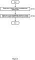
- a first step (S101) the Rydberg-atom based RF detector 120 is operated so as to excite electrons of the Rubidium atoms in the silica bulb 122 to the predetermined Rydberg state. As noted above, this is achieved by passing the probe and coupling signals through the silica bulb 122 at their respective frequencies. A transition from this predetermined Rydberg state to the ground state is forbidden (or at least has a very long decay period). However, an electron may be further excited to the further Rydberg state by an RF signal transmitted by the wireless transmitter 110 at 3.6GHz.
- the electron Upon excitation by the RF signal, the electron will spontaneously decay to its ground state by a process of fluorescence.
- the most probable decay option is the decay directly to the ground state.
- the decay from the further Rydberg state directly to the ground state involves the fluorescent emission of a photon having a wavelength of 297.96nm. This photon is within the spectral window of the detector 127.
- Other decay options from the further Rydberg state to the ground state are possible, such as via one or more intermediate states, wherein each decay between two states involves the fluorescent emission of a photon at a frequency corresponding with the energy difference between those two states.
- One or more of these characteristic photon frequencies are within the spectral window of the detector 127.
- the detector 127 detects one or more photons within its spectral window.
- the detector 127 may detect a single photon having a frequency corresponding to the decay path from the further Rydberg state directly to the ground state, or of at least one of the two or more photons having frequencies corresponding to the difference in energy states in an indirect decay path from the further Rydberg state to the ground state via one or more intermediate states.
- Detection of these one or more characteristic photons is an indirect detection of a photon of the wireless signal transmitted by the wireless transmitter 110 that excited an electron from the predetermined Rydberg state to the further Rydberg state (as the transition to the ground state from the predetermined Rydberg state is forbidden and the coupling laser is centred on the transition to the predetermined Rydberg state and has a linewidth less than the spacing to the further Rydberg state). Therefore, detection of the characteristic photon implies that the electron has been excited - by the photon of the wireless signal transmitted by the wireless transmitter 110 - from the predetermined Rydberg state to the further Rydberg state.
- the Rydberg-atom based RF detector 120 is a single RF photon detector that indirectly detects the single RF photon by directly detecting one or more characteristic photons in a decay path from the further Rydberg state to the ground state.
- the Rydberg-atom based RF detector 120 offers improved sensitivity than existing Rydberg-atom based RF detectors that rely on the absorption or interferometric detection techniques (which, as noted above, both require a sufficient number of photons to cause a detectable change in intensity of the probe signal above background noise).
- the Rydberg-atom based RF detector 120 exploits two properties to realise this benefit.
- the reflective coating inside the silica bulb 122 ensures that any photon emitted in the decay path from the further Rydberg state to the ground state that does not directly enter the detector 127 is internally reflected into the detector 127 by one or more reflections.
- the wireless telecommunications network 200 includes a wireless transmitter 210 and a Rydberg-atom based RF detector 220.
- the Rydberg-atom based RF detector 220 includes an optical fibre 221, a probe laser 223, a coupling laser 225, a detector 227, a housing 228, and a vapour cell 229.
- the Rydberg-atom based RF detector 220 of this second embodiment is configured to transmit counter-propagating probe and coupling signals through the vapour cell 229 (which overlap during at least part of their respective passages of the vapour cell 229) so as to excite electrons of the Rubidium-85 atoms contained within the vapour cell 229 to a predetermined Rydberg state (i.e. 83D_ ⁇ 5/2 ⁇ ).
- a predetermined Rydberg state i.e. 83D_ ⁇ 5/2 ⁇
- wireless signals transmitted by the wireless transmitter 210 at 3.6GHz that pass through the vapour cell 229 will excite electrons from this predetermined Rydberg state (83D_ ⁇ 5/2 ⁇ ) to a further Rydberg state (84P_ ⁇ 3/2 ⁇ ).
- the vapour cell 229 is constructed out of a material (e.g. acrylic, silicone, quartz or silica) that is transparent to photons emitted in a decay path from the further Rydberg state to the ground state.
- a material e.g. acrylic, silicone, quartz or silica
- the housing 228 is configured to only allow wireless signals inside the housing 228 (and therefore pass through the vapour cell 229) that arrive in a particular direction. This is achieved, in this embodiment, by constructing the housing 228 from an insulating material that prevents passage of wireless signals at the frequency of the wireless signals transmitted by the wireless transmitter 210, and having one or more passageways in the housing 228 (e.g. an opening or a section constructed from a material that is transparent to wireless signals at the frequency used by the wireless transmitter 210) being positioned and aligned on a predetermined axis so as to only allow wireless signals inside the housing 228 that arrive in the particular direction.
- an insulating material that prevents passage of wireless signals at the frequency of the wireless signals transmitted by the wireless transmitter 210
- one or more passageways in the housing 228 e.g. an opening or a section constructed from a material that is transparent to wireless signals at the frequency used by the wireless transmitter 210) being positioned and aligned on a predetermined axis so as to only allow wireless signals inside the housing 2
- the interior surface of the housing 228 is coated with a dielectric mirror coating (such as Hafnium Dioxide, as described above).
- the housing 228 is shaped so as to reflect photons passing out of the vapour cell 229 (that are emitted during a decay from the further Rydberg state to the ground state) to the detector 227.
- This shape may include a spherical section and a parabolic section so as to reflect the photons to the detector 227.
- the detector 227 is again a single photon detector, such as a Single-Photon-Avalanche-Diode (SPAD) or photomultiplier tube (PMT) as described above.
- the spectral window of the detector 227 (that is, the range of frequencies within which the single-photon detector 227 may detect an individual photon) is configurable so as to detect a photon (or photons) emitted in a decay path of an electron from the further Rydberg state to the ground state.
- the Rydberg-atom based RF detector 220 again includes a local power source to power the detector 227.
- the method of the first embodiment, as described above, may be applied to this second embodiment such that a single photon of the wireless signal transmitted by the wireless transmitter 210 in the RF region of the electromagnetic spectrum may be indirectly detected by the detector 227.
- a detection event is indicative of a single photon of a wireless signal arriving at the Rydberg-atom based RF detector 220 in a particular direction, corresponding with the axis of the passageway in the housing 228.
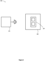
- FIG. 4 illustrates an end-to-end Quantum Key Distribution (QKD) system 300 having a transmitter 310 and a receiver 320.
- the transmitter 310 is configured to transmit wireless signals (containing polarisation-encoded qubits, as described below) at 3.6GHz.
- the receiver 320 includes a photon polarisation detector module 327.
- the photon polarisation detector module 327 includes a first and second Rydberg-atom based RF detector that are each based on the Rydberg-atom based RF detectors of the first or second embodiment above and are therefore configured to detect the 3.6GHz wireless signals transmitted by the transmitter 310.
- the first and second Rydberg-atom based RF detectors include polarisation filters which only allow wireless signals having a particular polarisation to pass through the detector and excite the atomic medium.
- the first Rydberg-atom based RF detector uses a first polarisation filter such that a wireless signal having the first polarisation (that is, 0 degrees) may pass through the first polarisation filter and through the atomic medium of the silica bulb/vapour cell (so as to cause a transition from the predetermined Rydberg state to the further Rydberg state), but a wireless signal having any other polarisation (including 45 degrees, 90 degrees or 135 degrees) may not pass through the first polarisation filter (and therefore does not pass through the atomic medium of the silica bulb/vapour cell which may otherwise cause a transition from the predetermined Rydberg state to the further Rydberg state).
- the second Rydberg-atom based RF detector uses a second polarisation filter such that a wireless signal having a second polarisation (that is, 90 degrees) may pass through the second polarisation filter and through the atomic medium of the silica bulb/vapour cell (so as to cause a transition from the predetermined Rydberg state to the further Rydberg state), but a wireless signal having the any other polarisation (including 0 degrees, 45 degrees or 135 degrees) may not pass through the second polarisation filter (and therefore does not pass through the atomic medium of the silica bulb/vapour cell which may otherwise cause a transition from the predetermined Rydberg state to the further Rydberg state).
- a wireless signal having a second polarisation that is, 90 degrees
- a wireless signal having the any other polarisation including 0 degrees, 45 degrees or 135 degrees
- the first Rydberg-atom based RF detector uses a third polarisation filter such that a wireless signal having a third polarisation (that is, 45 degrees) may pass through the third polarisation filter and through the atomic medium of the silica bulb/vapour cell (so as to cause a transition from the predetermined Rydberg state to the further Rydberg state), but a wireless signal having the any other polarisation (including 0 degrees, 90 degrees or 135 degrees) may not pass through the third polarisation filter (and therefore does not pass through the atomic medium of the silica bulb/vapour cell which may otherwise cause a transition from the predetermined Rydberg state to the further Rydberg state).
- a wireless signal having a third polarisation that is, 45 degrees
- a wireless signal having the any other polarisation including 0 degrees, 90 degrees or 135 degrees
- the second Rydberg-atom based RF detector uses a fourth polarisation filter such that a wireless signal having the fourth polarisation (that is, 135 degrees) may pass through the fourth polarisation filter and through the atomic medium of the silica bulb/vapour cell (so as to cause a transition from the predetermined Rydberg state to the further Rydberg state), but a wireless signal having the any other polarisation (including 0 degrees, 45 degrees or 90 degrees) will not pass through the fourth polarisation filter (and therefore does not pass through the atomic medium of the silica bulb/vapour cell which may otherwise cause a transition from the predetermined Rydberg state to the further Rydberg state).
- the photon polarisation detector module 327 may switch between a first state, in which it is configured to detect 0 degree polarisation at the first Rydberg-atom based RF detector and detect 90 degree polarisation at the second Rydberg-atom based RF detector, and a second state, in which it is configured to detect 45 degree polarisation at the first Rydberg-atom based RF detector and detect 135 degree polarisation at the second Rydberg-atom based RF detector.
- the QKD system 300 of this third embodiment utilises polarisation-encoded qubits to communicate an encryption (that is, cryptographic) key between the transmitter 310 and receiver 320.
- This may be based, for example, on the BB84 protocol, in which the transmitter 310 transmits qubits encoded according to a first base (in which a 0 degree polarisation corresponds to bit value 0 and a 90 degree polarisation corresponds to bit value 1) or second base (in which a 45 degree polarisation corresponds to bit value 0 and a 135 degree polarisation corresponds to bit value 1) to the receiver 320.
- the receiver 320 measures the qubits using either the first base (in which the photon polarisation detector module 327 is in the first state such that 0 degree polarisation qubits are detected at the first Rydberg-atom based RF detector and 90 degree polarisation qubits are detected at the second Rydberg-atom based RF detector) or the second base (in which the photon polarisation detector module 327 is in the second state such that 45 degree polarisation qubits are detected at the first Rydberg-atom based RF detector and 135 degree polarisation qubits are detected at the second Rydberg-atom based RF detector).
- the transmitter 310 and receiver 320 may communicate to determine which bases were used to transmit each qubit, such that the receiver 320 may identify the qubits that were successfully received. This protocol may be used to communicate the encryption key between the transmitter 310 and receiver 320.
- a receiver may comprise a first Rydberg-atom based RF receiver based on either the first or second embodiments above and configured to detect a first polarisation, and the receiver may further comprise a second Rydberg-atom based RF receiver based on the either the first or second embodiments above and configured to detect a second polarisation.
- the first and second polarisations may be perpendicular.
- This receiver may then be used to receive (that is, demodulate) data that is encoded by polarisation in a sequence of photons (for example, any photon having the first polarisation corresponds to bit value 0 and any photon having the second polarisation corresponds to bit value 1).
- this further embodiment may be used to communicate data of any form between the transmitter and receiver, and the QKD implementation of the third embodiment is just one example.
- QKD implementations are possible utilising polarisation-encoded qubits using a plurality of Rydberg-atom based RF detectors - each configured to detect a particular polarisation.
- the Rydberg-atom based RF detectors were adapted to detect photons of a particular polarisation by using a polarisation filter.
- this is non-essential and the detectors may be configured to detect photons of a particular polarisation in other ways, such as by being excited by probe and coupling lasers having a particular polarisation.
- the wireless signals transmitted to the Rydberg-atom based RF detectors have a frequency of 3.6GHz and each photon excites an electron from the predetermined Rydberg state (83D_ ⁇ 5/2 ⁇ ) to a further Rydberg state (84P_ ⁇ 3/2 ⁇ ).
- the subsequent decay from the further Rydberg state to the ground state involves the fluorescent emission of a photon at 297.96nm, which is detectable using single-photon detectors.
- the Rydberg-atom based RF detectors may be configured to detect single photons at other frequencies using the same technique (that is, by detecting one or more characteristic photons emitted during decay to the ground state).
- the predetermined Rydberg state may be selected (by configuration of the probe and coupling signals) at a relatively high quantum number, such as the Rb 149D_ ⁇ 5/2 ⁇ state.
- An electron may then be excited from this predetermined Rydberg state to a further Rydberg state (Rb 150P_ ⁇ 3/2 ⁇ ) by an RF photon having a frequency of 605MHz and the subsequent direct decay to the ground state involves the fluorescent emission of a photon at 296.86nm, which is again detectable using single-photon detectors.
- the predetermined Rydberg state may instead be selected (by configuration of the probe and coupling signals) at a relatively low quantum number, such as Rb 6D_ ⁇ 5/2 ⁇ .
- the Rydberg-atom based detectors may be used to indirectly detect photons having a relatively long wavelength (or relatively low frequency) by detecting characteristic photons emitted during decay to the ground state that have a relatively short wavelength (or relatively high frequency).
- the photons being indirectly detected may be in the RF, microwave and infrared ranges of the electromagnetic spectrum, and the photons being detected during decay to the ground state may be in the visible and ultraviolet ranges of the electromagnetic spectrum.
- the embodiments above describe a ladder EIT effect using a probe signal and a coupling signal.
- electrons may be elevated to a Rydberg state using any other form of EIT effect (e.g. lambda or Vee), and may use more than two signals.
- the skilled person will also understand that it is non-essential that the detectors use Rubidium-85 atoms, as other alkali metals, such as Caesium or Strontium, may be used instead.
- the single-photon detector in each embodiment may be configured with a spectral window to capture one or more of the characteristic photons of a decay path from the further Rydberg state to the ground state.
- the direct decay from the further Rydberg state to the ground state is the most probable transition, but there is typically a probability distribution of transitions from any specific further Rydberg state to the ground state, which involve the emission of one or more characteristic photons. Detection of at least one of these characteristic photons is deemed an indirect detection of an RF photon at the Rydberg-atom based RF detector.
Landscapes
- Physics & Mathematics (AREA)
- Electromagnetism (AREA)
- Engineering & Computer Science (AREA)
- Computer Networks & Wireless Communication (AREA)
- Signal Processing (AREA)
- General Physics & Mathematics (AREA)
- Optics & Photonics (AREA)
- Photometry And Measurement Of Optical Pulse Characteristics (AREA)
Priority Applications (5)
| Application Number | Priority Date | Filing Date | Title |
|---|---|---|---|
| EP22173349.6A EP4277166A1 (de) | 2022-05-13 | 2022-05-13 | Detektor für elektromagnetische felder |
| US18/863,938 US12289135B2 (en) | 2022-05-13 | 2023-04-11 | Electromagnetic field detector |
| EP23718757.0A EP4487501B1 (de) | 2022-05-13 | 2023-04-11 | Detektor für elektromagnetische felder |
| CN202380037718.5A CN119174120B (zh) | 2022-05-13 | 2023-04-11 | 电磁场检测器 |
| PCT/EP2023/059390 WO2023217473A1 (en) | 2022-05-13 | 2023-04-11 | Electromagnetic field detector |
Applications Claiming Priority (1)
| Application Number | Priority Date | Filing Date | Title |
|---|---|---|---|
| EP22173349.6A EP4277166A1 (de) | 2022-05-13 | 2022-05-13 | Detektor für elektromagnetische felder |
Publications (1)
| Publication Number | Publication Date |
|---|---|
| EP4277166A1 true EP4277166A1 (de) | 2023-11-15 |
Family
ID=82156740
Family Applications (2)
| Application Number | Title | Priority Date | Filing Date |
|---|---|---|---|
| EP22173349.6A Ceased EP4277166A1 (de) | 2022-05-13 | 2022-05-13 | Detektor für elektromagnetische felder |
| EP23718757.0A Active EP4487501B1 (de) | 2022-05-13 | 2023-04-11 | Detektor für elektromagnetische felder |
Family Applications After (1)
| Application Number | Title | Priority Date | Filing Date |
|---|---|---|---|
| EP23718757.0A Active EP4487501B1 (de) | 2022-05-13 | 2023-04-11 | Detektor für elektromagnetische felder |
Country Status (4)
| Country | Link |
|---|---|
| US (1) | US12289135B2 (de) |
| EP (2) | EP4277166A1 (de) |
| CN (1) | CN119174120B (de) |
| WO (1) | WO2023217473A1 (de) |
Cited By (1)
| Publication number | Priority date | Publication date | Assignee | Title |
|---|---|---|---|---|
| US20240210457A1 (en) * | 2021-05-12 | 2024-06-27 | The Secretary Of State For Defence | Rydberg radio sensor |
Citations (3)
| Publication number | Priority date | Publication date | Assignee | Title |
|---|---|---|---|---|
| US4024396A (en) * | 1976-05-10 | 1977-05-17 | Stanford Research Institute | Method and apparatus for detection utilizing Rydberg levels |
| CN111490825A (zh) * | 2020-05-15 | 2020-08-04 | 暨南大学 | 基于反谐振空芯光纤的数据传输且同时分发量子密钥方法 |
| GB2588754A (en) * | 2019-10-24 | 2021-05-12 | British Telecomm | Wireless telecommunications network |
Family Cites Families (15)
| Publication number | Priority date | Publication date | Assignee | Title |
|---|---|---|---|---|
| US9507004B2 (en) * | 2013-07-31 | 2016-11-29 | The Government Of The United States Of America, As Represented By The Secretary Of Commerce | Electron spin resonance spectrometer and method for using same |
| US9500725B2 (en) * | 2013-08-06 | 2016-11-22 | Northrop Grumman Systems Corporation | Probe beam frequency stabilization in an atomic sensor system |
| US10256917B2 (en) * | 2016-09-27 | 2019-04-09 | Raytheon Company | Optically sensed demodulation systems and methods for optical communications |
| JP7470643B2 (ja) | 2017-12-18 | 2024-04-18 | リッドバーグ テクノロジーズ インコーポレイテッド | 原子ベースの電磁場感知要素および測定システム |
| CN110401492B (zh) * | 2018-07-27 | 2020-08-21 | 中国计量科学研究院 | 一种基于量子效应的无线电调幅信号接收方法及调幅量子接收机 |
| US11349569B2 (en) * | 2018-10-26 | 2022-05-31 | Raytheon Company | Methods and apparatus for implementing an optical transceiver using a vapor cell |
| US10763966B1 (en) * | 2019-03-25 | 2020-09-01 | Otago Innovation Limited | Data communications system using an optical antenna |
| CN109765213B (zh) * | 2019-03-27 | 2024-03-29 | 苏州威邦震电光电技术有限公司 | 相干反斯托克斯拉曼散射显微镜成像装置 |
| CN110231332B (zh) * | 2019-07-03 | 2022-01-11 | 榆林学院 | 利用超陡滤波片简化的相干反斯托克斯拉曼散射光谱装置及方法 |
| EP4038826B1 (de) * | 2019-09-30 | 2025-12-24 | British Telecommunications public limited company | Verbesserungen bei quantenschlüsselverteilung |
| AU2021281437A1 (en) * | 2020-05-29 | 2022-12-22 | Rydberg Technologies Inc. | Atom-based closed-loop control for electromagnetic radiation measurement, communications, and information processing |
| GB2597260B (en) * | 2020-07-16 | 2022-12-07 | British Telecomm | Electromagnetic field receiver |
| EP4264295A4 (de) * | 2020-12-17 | 2024-09-18 | Northrop Grumman Systems Corporation | Elektrometersensor-steuersystem |
| GB2605650B (en) * | 2021-04-09 | 2023-06-07 | British Telecomm | Electromagnetic field detector |
| GB2606167B (en) * | 2021-04-27 | 2023-06-21 | British Telecomm | Wireless transceiver |
-
2022
- 2022-05-13 EP EP22173349.6A patent/EP4277166A1/de not_active Ceased
-
2023
- 2023-04-11 EP EP23718757.0A patent/EP4487501B1/de active Active
- 2023-04-11 CN CN202380037718.5A patent/CN119174120B/zh active Active
- 2023-04-11 US US18/863,938 patent/US12289135B2/en active Active
- 2023-04-11 WO PCT/EP2023/059390 patent/WO2023217473A1/en not_active Ceased
Patent Citations (3)
| Publication number | Priority date | Publication date | Assignee | Title |
|---|---|---|---|---|
| US4024396A (en) * | 1976-05-10 | 1977-05-17 | Stanford Research Institute | Method and apparatus for detection utilizing Rydberg levels |
| GB2588754A (en) * | 2019-10-24 | 2021-05-12 | British Telecomm | Wireless telecommunications network |
| CN111490825A (zh) * | 2020-05-15 | 2020-08-04 | 暨南大学 | 基于反谐振空芯光纤的数据传输且同时分发量子密钥方法 |
Non-Patent Citations (1)
| Title |
|---|
| HAFNIUM DIOXIDE: "High-reflectivity Hf02/Si02 ultraviolet mirrors", APPLIED OPTICS, vol. 41, 2002, pages 3256 - 3261 |
Cited By (2)
| Publication number | Priority date | Publication date | Assignee | Title |
|---|---|---|---|---|
| US20240210457A1 (en) * | 2021-05-12 | 2024-06-27 | The Secretary Of State For Defence | Rydberg radio sensor |
| US12436177B2 (en) * | 2021-05-12 | 2025-10-07 | The Secretary Of State For Defence | Rydberg radio sensor |
Also Published As
| Publication number | Publication date |
|---|---|
| EP4487501B1 (de) | 2025-10-08 |
| US20250112709A1 (en) | 2025-04-03 |
| US12289135B2 (en) | 2025-04-29 |
| CN119174120A (zh) | 2024-12-20 |
| WO2023217473A1 (en) | 2023-11-16 |
| EP4487501A1 (de) | 2025-01-08 |
| CN119174120B (zh) | 2025-07-18 |
Similar Documents
| Publication | Publication Date | Title |
|---|---|---|
| CN114424111B (zh) | 传播信号的设备和系统以及电磁场检测器及操作其的方法 | |
| Musiał et al. | Plug&play fiber‐coupled 73 kHz single‐photon source operating in the telecom o‐band | |
| CN104360152B (zh) | 一种基于nv色心金刚石的微波传感器 | |
| US20020021765A1 (en) | Direct electrical-to-optical conversion and light modulation in micro whispering-gallery-mode resonators | |
| CN101794033B (zh) | 集合式拉曼增强原子蒸汽滤光信号方法与装置 | |
| GB2588754A (en) | Wireless telecommunications network | |
| EP4487501B1 (de) | Detektor für elektromagnetische felder | |
| US20170343620A1 (en) | Magneto-optical defect center device including light pipe with optical coatings | |
| WO2022184421A1 (en) | Electromagnetic field detector | |
| Ali et al. | A Gigabit VLC receiver that incorporates a fluorescent antenna and a SiPM | |
| KR20210075402A (ko) | 다이아몬드 질소 공석 자기장 센서 | |
| GB2618617A (en) | Electromagnetic field detector | |
| EP4320451B1 (de) | Detektor für elektromagnetisches feld | |
| US20240243816A1 (en) | Weak pulse detection for discrete-variable quantum key distribution receiver and method | |
| AU2023307880B2 (en) | Electrometer system with rydberg decay fluorescence detection | |
| US5136168A (en) | Atomic resonance filter detector employing inert buffer gas | |
| CN114785419B (zh) | 信号接收装置与信号接收方法 | |
| US20250244414A1 (en) | Ring resonator magnetometer with absorbent material | |
| Georgieva et al. | Metrological characterization of a commercial single-photon source with high photon flux emission | |
| US11328773B2 (en) | Quantum storage device | |
| Castelletto et al. | Narrow magneto-optical transitions in Erbium implanted silicon carbide-on-insulator | |
| Cehelnik et al. | Quantum counter photodetectors: a new design | |
| Lyasota et al. | Narrow magneto-optical transitions in Erbium implanted silicon carbide-on-insulator | |
| Meyer et al. | Two Opto-Atomic Devices for Classical and Quantum Communication | |
| Peeters et al. | Enhancement of single photon emission from quantum dots using arrays of nanoantennas |
Legal Events
| Date | Code | Title | Description |
|---|---|---|---|
| PUAI | Public reference made under article 153(3) epc to a published international application that has entered the european phase |
Free format text: ORIGINAL CODE: 0009012 |
|
| STAA | Information on the status of an ep patent application or granted ep patent |
Free format text: STATUS: THE APPLICATION HAS BEEN PUBLISHED |
|
| AK | Designated contracting states |
Kind code of ref document: A1 Designated state(s): AL AT BE BG CH CY CZ DE DK EE ES FI FR GB GR HR HU IE IS IT LI LT LU LV MC MK MT NL NO PL PT RO RS SE SI SK SM TR |
|
| STAA | Information on the status of an ep patent application or granted ep patent |
Free format text: STATUS: THE APPLICATION HAS BEEN REFUSED |
|
| 18R | Application refused |
Effective date: 20231127 |