EP3940318B1 - Anlage zur produktion von kunstschnee - Google Patents
Anlage zur produktion von kunstschnee Download PDFInfo
- Publication number
- EP3940318B1 EP3940318B1 EP21185364.3A EP21185364A EP3940318B1 EP 3940318 B1 EP3940318 B1 EP 3940318B1 EP 21185364 A EP21185364 A EP 21185364A EP 3940318 B1 EP3940318 B1 EP 3940318B1
- Authority
- EP
- European Patent Office
- Prior art keywords
- fluid
- turbine
- snow
- air
- power generator
- Prior art date
- Legal status (The legal status is an assumption and is not a legal conclusion. Google has not performed a legal analysis and makes no representation as to the accuracy of the status listed.)
- Active
Links
Images


Classifications
-
- F—MECHANICAL ENGINEERING; LIGHTING; HEATING; WEAPONS; BLASTING
- F25—REFRIGERATION OR COOLING; COMBINED HEATING AND REFRIGERATION SYSTEMS; HEAT PUMP SYSTEMS; MANUFACTURE OR STORAGE OF ICE; LIQUEFACTION SOLIDIFICATION OF GASES
- F25C—PRODUCING, WORKING OR HANDLING ICE
- F25C3/00—Processes or apparatus specially adapted for producing ice or snow for winter sports or similar recreational purposes, e.g. for sporting installations; Producing artificial snow
- F25C3/04—Processes or apparatus specially adapted for producing ice or snow for winter sports or similar recreational purposes, e.g. for sporting installations; Producing artificial snow for sledging or ski trails; Producing artificial snow
-
- F—MECHANICAL ENGINEERING; LIGHTING; HEATING; WEAPONS; BLASTING
- F01—MACHINES OR ENGINES IN GENERAL; ENGINE PLANTS IN GENERAL; STEAM ENGINES
- F01D—NON-POSITIVE DISPLACEMENT MACHINES OR ENGINES, e.g. STEAM TURBINES
- F01D1/00—Non-positive-displacement machines or engines, e.g. steam turbines
- F01D1/18—Non-positive-displacement machines or engines, e.g. steam turbines without stationary working-fluid guiding means
-
- F—MECHANICAL ENGINEERING; LIGHTING; HEATING; WEAPONS; BLASTING
- F01—MACHINES OR ENGINES IN GENERAL; ENGINE PLANTS IN GENERAL; STEAM ENGINES
- F01D—NON-POSITIVE DISPLACEMENT MACHINES OR ENGINES, e.g. STEAM TURBINES
- F01D15/00—Adaptations of machines or engines for special use; Combinations of engines with devices driven thereby
- F01D15/10—Adaptations for driving, or combinations with, electric generators
-
- F—MECHANICAL ENGINEERING; LIGHTING; HEATING; WEAPONS; BLASTING
- F03—MACHINES OR ENGINES FOR LIQUIDS; WIND, SPRING, OR WEIGHT MOTORS; PRODUCING MECHANICAL POWER OR A REACTIVE PROPULSIVE THRUST, NOT OTHERWISE PROVIDED FOR
- F03D—WIND MOTORS
- F03D9/00—Adaptations of wind motors for special use; Combinations of wind motors with apparatus driven thereby; Wind motors specially adapted for installation in particular locations
- F03D9/20—Wind motors characterised by the driven apparatus
-
- F—MECHANICAL ENGINEERING; LIGHTING; HEATING; WEAPONS; BLASTING
- F25—REFRIGERATION OR COOLING; COMBINED HEATING AND REFRIGERATION SYSTEMS; HEAT PUMP SYSTEMS; MANUFACTURE OR STORAGE OF ICE; LIQUEFACTION SOLIDIFICATION OF GASES
- F25D—REFRIGERATORS; COLD ROOMS; ICE-BOXES; COOLING OR FREEZING APPARATUS NOT OTHERWISE PROVIDED FOR
- F25D17/00—Arrangements for circulating cooling fluids; Arrangements for circulating gas, e.g. air, within refrigerated spaces
- F25D17/02—Arrangements for circulating cooling fluids; Arrangements for circulating gas, e.g. air, within refrigerated spaces for circulating liquids, e.g. brine
-
- F—MECHANICAL ENGINEERING; LIGHTING; HEATING; WEAPONS; BLASTING
- F03—MACHINES OR ENGINES FOR LIQUIDS; WIND, SPRING, OR WEIGHT MOTORS; PRODUCING MECHANICAL POWER OR A REACTIVE PROPULSIVE THRUST, NOT OTHERWISE PROVIDED FOR
- F03D—WIND MOTORS
- F03D9/00—Adaptations of wind motors for special use; Combinations of wind motors with apparatus driven thereby; Wind motors specially adapted for installation in particular locations
-
- F—MECHANICAL ENGINEERING; LIGHTING; HEATING; WEAPONS; BLASTING
- F05—INDEXING SCHEMES RELATING TO ENGINES OR PUMPS IN VARIOUS SUBCLASSES OF CLASSES F01-F04
- F05D—INDEXING SCHEME FOR ASPECTS RELATING TO NON-POSITIVE-DISPLACEMENT MACHINES OR ENGINES, GAS-TURBINES OR JET-PROPULSION PLANTS
- F05D2220/00—Application
- F05D2220/20—Application within closed fluid conduits, e.g. pipes
-
- F—MECHANICAL ENGINEERING; LIGHTING; HEATING; WEAPONS; BLASTING
- F05—INDEXING SCHEMES RELATING TO ENGINES OR PUMPS IN VARIOUS SUBCLASSES OF CLASSES F01-F04
- F05D—INDEXING SCHEME FOR ASPECTS RELATING TO NON-POSITIVE-DISPLACEMENT MACHINES OR ENGINES, GAS-TURBINES OR JET-PROPULSION PLANTS
- F05D2220/00—Application
- F05D2220/70—Application in combination with
- F05D2220/76—Application in combination with an electrical generator
-
- F—MECHANICAL ENGINEERING; LIGHTING; HEATING; WEAPONS; BLASTING
- F25—REFRIGERATION OR COOLING; COMBINED HEATING AND REFRIGERATION SYSTEMS; HEAT PUMP SYSTEMS; MANUFACTURE OR STORAGE OF ICE; LIQUEFACTION SOLIDIFICATION OF GASES
- F25C—PRODUCING, WORKING OR HANDLING ICE
- F25C2303/00—Special arrangements or features for producing ice or snow for winter sports or similar recreational purposes, e.g. for sporting installations; Special arrangements or features for producing artificial snow
- F25C2303/044—Snow making using additional features, e.g. additives, liquid gas
-
- F—MECHANICAL ENGINEERING; LIGHTING; HEATING; WEAPONS; BLASTING
- F25—REFRIGERATION OR COOLING; COMBINED HEATING AND REFRIGERATION SYSTEMS; HEAT PUMP SYSTEMS; MANUFACTURE OR STORAGE OF ICE; LIQUEFACTION SOLIDIFICATION OF GASES
- F25C—PRODUCING, WORKING OR HANDLING ICE
- F25C2303/00—Special arrangements or features for producing ice or snow for winter sports or similar recreational purposes, e.g. for sporting installations; Special arrangements or features for producing artificial snow
- F25C2303/048—Snow making by using means for spraying water
- F25C2303/0481—Snow making by using means for spraying water with the use of compressed air
Definitions
- This electrical energy is mainly used to power electronics, sensors, actuators, motors or servomotors, as well as heating snowmaking devices.
- Snowmaking devices not connected to the network must then be autonomous in electrical energy, this electrical energy being produced by battery systems, solar panels (use of solar energy) or even wind turbines (use of wind energy).
- the current produced by the electricity generator can be used to power the installation's management systems.
- the present invention provides an artificial snow production installation according to claim 1.
- Such an installation structure has the advantage of using the energy from the resources needed for snow production to operate the snowmaker. It does not require any other energy source.
- the system is purely mechanical and does not require maintenance, recharging, or cleaning, unlike known solutions based on solar panels or batteries.
- the snow-making device 2 can be of any type, in particular of the low or high pressure type.
- the snow-making device 2 is of the high-pressure type with external air/water mixture, equipped with water spray nozzles and at least one nozzle for producing nucleating agents.
- the snow production head 21 of the snow-making device 2 is mounted at the end of a pole 22 which can reach several meters in height.
- a box 7 containing the control means 5 is mounted at the base of the pole 22.
- the box 7 contains in particular one or more distributors actuated by motors (piston system) or by solenoid valves to regulate the snow gun.
- the water fluid line 3 is connected to a main water line E which runs along the ski slope preferably to supply several snow-making devices.
- a manual valve 8 (called water valve 8) allows an operator to supply the water fluid line 3 from the main water line E, or to stop this supply.
- the water pressure in the water fluid line 3 can be between 3 bar and 100 bar; and the water flow rate can be between 0.1 m 3 /h and 50 m 3 /h.
- the air fluid line 4 is connected to a main air line A which runs along the ski slope to supply several snowmaking devices.
- a manual valve 9 (called air valve 9) allows an operator to supply the air fluid line 4 from the main air line A, or to stop this supply.
- the air pressure in the air fluid line 4 can be between 1 bar and 10 bar; and the air flow rate can be between 5 Nm 3 /h and 500 Nm 3 /h.
- the operating principle of the electricity generator 6 is to transform the kinetic/mechanical energy of the air into electrical energy.
- the compressed air circulates around the blades of the turbine 61 generating its rotational movement.
- the turbine 61 is driven in rotation by the air flow. This rotation drives (via a shaft) an alternator which makes it possible to produce at least part of the electrical energy necessary for the proper operation of the snow-making device 2.
- the turbine 61 itself drives the associated alternator which converts the energy of the compressed air into electrical energy; and this electrical energy is regulated in a regulating device 10, then stored in energy storage means 10a.
- the energy storage means 10a of the produced electrical energy may consist of conventional batteries or supercapacitors.
- These energy storage means 10a are charged in parallel so that the electrical supply begins as soon as the turbine 61 is in motion. Preferably, they have the capacity to temporarily restore more electrical energy than that delivered by the turbine, which makes it possible, for example, to control a higher power actuator.
- the regulating device 10 consists of a regulating card possibly integrating the energy storage means 10a. This regulating card can be integrated into a box associated with the electricity generator.
- This electrical energy is used to power the control means 5 necessary for managing the operation of the snow-making device 2.
- the water valve 8 and the air valve 9 can be equipped with actuators and controlled by the electricity produced. In this case it is thus possible to adapt the flow rate of the snow gun 2 to the ambient temperature, and to stop it in the event of an emergency or if this ambient temperature no longer allows snow production.
- Water circuit 3 is connected directly to the water circuit of snowmaking device 2.
- the controller 51 closes the water valve 8 then the air valve 9 and the system goes into standby mode, monitoring the ambient air temperature and the battery charge level.
- Messages can be sent informing a remote computer system of the status of the system (sensor measurements, estimated flow rates, charge level of energy storage systems).
- the user manually opens the air valve 9 when he decides to operate the snowmaking device 2.
- the 51 automaton and all or part of the organs can be powered by an external source such as a pre-charged portable electrical appliance battery.
- FIG. 2 illustrates a second embodiment of an installation 1' for producing artificial snow according to an example which is not part of the invention.
- the corresponding installation 1' comprises essentially the same components/devices as that described above in relation to the Figure 1 , but here, the electricity generator 6' is arranged on the water fluid pipe 3.
- the snow-making device 2 can be of any type, in particular low or high pressure type.
- a box 7 containing the control means 5 is mounted at the base of the pole 22.
- the box 7 contains in particular one or more distributors actuated by motors (piston system) or by solenoid valves to regulate the snow gun.
- the water fluid line 3 is connected to a main water line E which runs along the ski slope preferably to supply several snow-making devices.
- a manual valve 8 (called water valve 8) allows an operator to supply the water fluid line 3 from the main water line E, or to stop this supply.
- the water pressure in the water fluid line 3 can be between 3 bar and 100 bar; and the water flow rate can be between 0.1 m 3 /h and 50 m 3 /h.
- the operating principle of the 6' electricity generator is to transform the kinetic/mechanical energy of water into electrical energy.
- the pressurized water circulates around the blades of the turbine 61' generating its rotational movement.
- the turbine 61' itself drives the associated alternator which converts the energy of the pressurized water into electrical energy; and this electrical energy is regulated in a regulating device 10, then stored in energy storage means 10a.
- the energy storage means 10a may consist of conventional batteries or supercapacitors.
- the regulating device 10 consists of a regulating card possibly integrating the energy storage means 10a. This regulating card can be integrated into a box associated with the electricity generator.
- This electrical energy is used to power the control means 5 necessary for managing the operation of the snow-making device 2.
- the water valve 8 and the air valve 9 can be equipped with actuators and controlled by the electricity produced.
- a condensate drain system 14a is placed on the air fluid pipe 4 to limit the accumulation of water in the snow-making device 2.
- This condensate drain system 14a can be of the manual type (manual valve), or automatic (spring-loaded pop drain).
- the compressed air circuit 4 is connected directly to the air circuit of the snow-making device 2.
- the human/machine interface 13 may be optional and is implemented by a display associated with a wireless or wired communication link to a supervision system (computer, mobile application, WEB application, etc.).
- a supervision system computer, mobile application, WEB application, etc.
- the energy stored in the batteries or supercapacitors is sufficient to power the sensors 11 and allow the air valve 9 and the water valve 8 to open. In this case, if the ambient temperature is lower than a programmed threshold, the controller 51 requests the opening of the air valve 9 then the water valve 8.
- the electricity generator 6' then generates electricity which makes it possible to regulate the flow of the snow-making device 2 by controlling the actuators necessary to position the nozzles, valves or distributors.
- the user manually opens the air valve 9 when he decides to operate the snowmaking device, then the water valve 8.
- the electricity generator 6' then generates electricity which makes it possible to regulate the flow of the snow-making device 2 by controlling the actuators necessary to position the nozzles, valves or distributors.
- the user manually controls the snowmaking device 2, either via the controller 51 or by switches.
- the operator opens the air valve 9, either by the automaton 51, or manually if the battery charge level does not allow it, then the water valve 8.
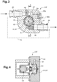
- FIGS. 3 and 4 detail the structure of a 6, 6' electricity generator capable of equipping the 1, 1' snowmaking production facilities of the figures 1 And 2 .
- This electricity generator 6, 6' comprises a turbine 61, 61' of the blade type, housed in a generator body 62.
- the axis or shaft 63 of the turbine 61, 61' is engaged with an alternator 64 for the production of electricity.
- This alternator 64 is intended to be connected to the regulating device 10 and to the batteries or super-capacitors of the storage means 10a of the electrical energy produced.
- the electricity generator 6, 6' comprises a fluid inlet 65 for the drive fluid (air or water as the case may be) of the turbine 61, 61', as well as a fluid outlet 66, with, between the two, a fluid transport channel 67.
- the fluid transport channel 67 connects the fluid inlet 65 and the fluid outlet 66; and a sector S of the turbine 61, 61' is arranged within a section of the transport channel 67 to allow it to be driven in rotation.
- the sector S of the turbine which is arranged in the fluid transport channel 67 is of the order of 180°.
- the flow rate or speed of the fluid can be adapted by at least one section restriction, in particular to ensure the rotation of the turbine 61, 61' at an optimal speed.
- such a means 68 for restricting the passage of the fluid can be provided downstream of the turbine 61, 61' (i.e. at the turbine outlet), in order to limit the speed of the fluid in the fluid transport channel 67.
- Such a passage restriction 68 can prove particularly advantageous on air, to limit the speed if the turbine is used alone without a snow gun.
- a passage restriction means 69 may be usefully placed to increase the fluid velocity and bring the fluid flow to a peripheral velocity sufficient to turn turbine 61, 61' (the speed is increased by creating a pressure drop in order to guarantee a minimum rotation speed at low pressure).
- the turbine 61, 61' of the electricity generator 6, 6' can be associated with just one of these passage restriction means 68, 69, or with both of these upstream and downstream passage restriction means 68, 69.
- the passage restriction means 68 and 69 preferably each consist of a removable part, to allow its removal or replacement in order to adjust the desired flow rates and speeds as desired. Such an adjustment can be obtained by a particular orifice diameter, a particular orifice shape or even a particular number of orifices.
- the snow production installation may comprise a “by-pass” pipe 70 which connects the fluid inlet 65 and the fluid outlet 66. It is understood that such a “by-pass” pipe 70 allows the passage of a portion of the fluid (water or air as the case may be) to supply the snow-making device 2 without passing through the electricity generator 6, 6'. This makes it possible to use only a portion of the energy of the fluid for the turbine, in the case of a significant energy source, so as not to be obliged to oversize the components of the turbine.
- the electricity generator 6, 6' can include an additional outlet 66a for the drive fluid of the turbine 61, 61'.
- the user has a choice of connecting the snow-making device 2 to the outputs 66 or 66a of the electricity generator 6, 6', in particular depending on the pressure and flow characteristics of the fluid upstream of said electricity generator 6, 6'.
- a plug-shaped sealing means 66b is provided for sealing the first outlet 66 or the second outlet 66a not used for the connection.
- outlets for the turbine drive fluid 61, 61' may be considered to increase the choice of connection depending on the pressure and flow characteristics of the fluid upstream of the electricity generator 6, 6'.
- the electricity generator 6, 6' is adapted so that its turbine 61, 61' withstands the operating air or water pressure. Its energy efficiency must be interesting and it must preferably minimize the energy taken from the air or water flow, otherwise it will cause a significant degradation in the performance of the snow-making device 2.
- This electricity generator 6, 6' is also preferably adapted to minimize the heating of the water or air flow. Indeed, the transformation of kinetic/mechanical energy into electrical energy causes the water or air flow to heat up due to the friction of the water or air on the blades of the turbine 61, 61'.
- the water or air temperature is an important parameter for the performance of the snow-making device 2, and a water or air temperature that is too high would cause a significant degradation of the performance of the snow-making device 2.
- the snow production facility is also advantageously equipped with all the device(s) necessary for the protection of people.
- the artificial snow production installation can comprise an electricity generator arranged on the water fluid pipe 3, and an electricity generator arranged on the air fluid pipe.
Landscapes
- Engineering & Computer Science (AREA)
- General Engineering & Computer Science (AREA)
- Mechanical Engineering (AREA)
- Thermal Sciences (AREA)
- Physics & Mathematics (AREA)
- Combustion & Propulsion (AREA)
- Chemical & Material Sciences (AREA)
- Sustainable Energy (AREA)
- Sustainable Development (AREA)
- Life Sciences & Earth Sciences (AREA)
- Power Engineering (AREA)
- Other Liquid Machine Or Engine Such As Wave Power Use (AREA)
- Buildings Adapted To Withstand Abnormal External Influences (AREA)
- Prostheses (AREA)
Claims (8)
- Anlage (1) zur Produktion von Kunstschnee mit - einer Beschneiungsvorrichtung (2), - einer Kanalisation für fließendes Wasser (3) zur Versorgung der Beschneiungsvorrichtung (2) mit Wasser, - einer Kanalisation für einen Luftfluß (4) zum Versorgen der Beschneiungsvorrichtung (2) mit Luft, - Steuerungsmitteln (5) zum Steuern des Betriebs der Beschneiungsvorrichtung (2), - einer Stromversorgung für die Versorgung der Steuerungsmittel (5) mit Strom,wobei die Stromversorgung einen Stromgenerator (6) aufweist, der auf der Kanalisation für einen Luftfluß (4) angeordnet ist,wobei der Stromgenerator (6) eine Turbine (61) aufweist, die geeignet ist, durch die Luft der Kanalisation für einen Luftfluß (4) angetrieben zu werden,dadurch gekennzeichnet, daß sie zwei Kondensatabflußsysteme (14, 15) aufweist, von denen eins (14) stromaufwärts und das andere (15) stromabwärts vom Stromgenerator (6) angeordnet ist und die beide dazu ausgelegt sind, das Ansammeln von Wasser im Stromgenerator (6) zu begrenzen.
- Anlage (1) zur Produktion von Kunstschnee gemäß Anspruch 1, dadurch gekennzeichnet, daß sie einen Wechselstromgenerator, der mit der Achse der Turbine für die Stromerzeugung in Eingriff ist, und Mittel zum Speichern der erzeugten elektrischen Energie vom Typ einer Batterie oder Batterien oder mit dem Wechselstromgenerator verbundenen Superkapazität(en) . aufweist.
- Anlage (1) zur Produktion von Kunstschnee gemäß einem der Ansprüche 1 oder 2, dadurch gekennzeichnet, daß sie eine Reglervorrichtung (10) aufweist, die geeignet ist, die erzeugte elektrische Energie zu regeln.
- Anlage (1) zur Produktion von Kunstschnee gemäß einem der Ansprüche 1 bis 3, dadurch gekennzeichnet, daß die Steuerungsmittel (5) mindestens einen Sensor (11) für einen (oder mehrere) Parameter aufweisen, der (die) unter den Windgeschwindigkeitssensoren (114), den Wasserdrucksensoren (112), den Luftdrucksensoren (111), den Umgebungstemperatur- und Umgebungsfeuchtigkeitssensoren (113) ausgewählt ist (sind), wobei der mindestens eine Parametersensor (11) durch die vom Stromgenerator (6) erzeugte elektrische Energie versorgt wird.
- Anlage (1) zur Produktion von Kunstschnee gemäß einem der Ansprüche 1 bis 4, dadurch gekennzeichnet, daß der Stromgenerator (6) einen Flüssigkeitseingang (65) für die Antriebsflüssigkeit der Turbine (61), mindestens einen Flüssigkeitsausgang (66, 66a) für die Antriebsflüssigkeit der Turbine (61), einen Transportkanal (67) für die Flüssigkeit, der den Flüssigkeitseingang (65) mit dem mindestens einen Flüssigkeitsausgang (66, 66a) verbindet, aufweist, wobei in einem Abschnitt des Transportkanals (67) für die Flüssigkeit ein Sektor (S, Sa) der Turbine (61) liegt, um deren Drehantrieb zu ermöglichen,
wobei der Transportkanal (67) für die Flüssigkeit ein Mittel (69) zum Begrenzen des Durchflusses für die Flüssigkeit aufweist, das stromaufwärts von der Turbine (61) angeordnet ist, um die Geschwindigkeit der Flüssigkeit im Transportkanal (67) zu erhöhen. - Anlage (1) zur Produktion von Kunstschnee gemäß einem der Ansprüche 1 bis 5, dadurch gekennzeichnet, daß der Stromgenerator (6) einen Flüssigkeitseingang (65) für die Antriebsflüssigkeit der Turbine (61), mindestens einen Flüssigkeitsausgang (66, 66a) für die Antriebsflüssigkeit der Turbine (6), einen Transportkanal (67) für die Flüssigkeit, der den Flüssigkeitseingang (65) mit dem mindestens einen Flüssigkeitsausgang (66, 66a) verbindet, aufweist, wobei in einem Abschnitt des Transportkanals (67) für die Flüssigkeit ein Sektor (S, Sa) der Turbine (6, 6') liegt, um deren Drehantrieb zu ermöglichen,
wobei der Transportkanal (67) für die Flüssigkeit ein Mittel (68) zum Begrenzen des Durchflusses für die Flüssigkeit aufweist, das stromabwärts von der Turbine (61) angeordnet ist, um die Geschwindigkeit der Flüssigkeit im Transportkanal (67) des Stromgenerators (6) zu begrenzen. - Anlage (1) zur Produktion von Kunstschnee gemäß einem der Ansprüche 1 bis 6, dadurch gekennzeichnet, daß der Stromgenerator (6) einen Flüssigkeitseingang (65) für die Antriebsflüssigkeit der Turbine (61), mindestens einen Flüssigkeitsausgang (66, 66a) für die Antriebsflüssigkeit der Turbine (61), einen Transportkanal (67) für die Flüssigkeit, der den Flüssigkeitseingang (65) mit dem mindestens einen Flüssigkeitsausgang (66, 66a) verbindet, aufweist, wobei in einem Abschnitt des Transportkanals (67) für die Flüssigkeit ein Sektor (S, Sa) der Turbine (61) liegt, um deren Drehantrieb zu ermöglichen,
wobei die Anlage (1) außerdem einen Kanalisationsbypass (70) aufweist, der den Flüssigkeitseingang (65) mit dem mindestens einen Flüssigkeitsausgang (66, 66a) verbindet, wobei der Kanalisationsbypass (70) den Durchfluß eines Teils der Flüssigkeit für die Versorgung der Beschneiungsvorrichtung (2) ermöglicht, ohne durch den Stromgenerator (6) zu fließen. - Anlage (1) zur Produktion von Kunstschnee gemäß einem der Ansprüche 1 bis 7, dadurch gekennzeichnet, daß der Stromgenerator (6) einen Eingang (65) für die Antriebsflüssigkeit der Turbine (6), zwei Ausgänge (66 und 66a) für die Antriebsflüssigkeit der Turbine (6), einen Transportkanal (67), der den Flüssigkeitseingang (65) mit den beiden Flüssigkeitsausgängen (66, 66a) verbindet, aufweist,wobei ein erster der Ausgänge (66) für die Flüssigkeit so angeordnet ist, daß ein erster Sektor (S) der Stromturbine (6) in einem Abschnitt des Transportkanals (67) liegt, undwobei ein zweiter der Ausgänge (66a) für die Flüssigkeit so angeordnet ist, daß ein zweiter Sektor (Sa) der Stromturbine (6) in einem Abschnitt des Transportkanals (67) liegt,wobei sich der erste Turbinensektor (S) und der zweite Turbinensektor (Sa) über Winkelbereiche mit unterschiedlichen Werten erstrecken, um über eine Auswahl der Anschlüsse, insbesondere in Abhängigkeit von den Merkmalen Druck und Flüssigkeitsdurchsatz stromaufwärts vom Stromgenerator (6), zu verfügen,wobei die Anlage (1) außerdem ein Verschlußmittel (66b) aufweist, das geeignet ist, den für den Anschluß nicht gebrauchten ersten Ausgang (66) oder zweiten Ausgang (66a) zu verschließen.
Applications Claiming Priority (1)
| Application Number | Priority Date | Filing Date | Title |
|---|---|---|---|
| FR2007392A FR3112596B1 (fr) | 2020-07-15 | 2020-07-15 | Installation de production de neige de culture |
Publications (2)
| Publication Number | Publication Date |
|---|---|
| EP3940318A1 EP3940318A1 (de) | 2022-01-19 |
| EP3940318B1 true EP3940318B1 (de) | 2025-07-02 |
Family
ID=72801716
Family Applications (1)
| Application Number | Title | Priority Date | Filing Date |
|---|---|---|---|
| EP21185364.3A Active EP3940318B1 (de) | 2020-07-15 | 2021-07-13 | Anlage zur produktion von kunstschnee |
Country Status (5)
| Country | Link |
|---|---|
| US (1) | US12455105B2 (de) |
| EP (1) | EP3940318B1 (de) |
| CN (1) | CN113945035B (de) |
| ES (1) | ES3042631T3 (de) |
| FR (1) | FR3112596B1 (de) |
Families Citing this family (1)
| Publication number | Priority date | Publication date | Assignee | Title |
|---|---|---|---|---|
| DE202022107105U1 (de) * | 2022-12-20 | 2023-03-08 | Technische Universität Chemnitz, Körperschaft des öffentlichen Rechts | Anlage zur Abkühlung mindestens eines Kältemittels und/oder mindestens eines Kälteträgers in einem offenen Prozess |
Citations (4)
| Publication number | Priority date | Publication date | Assignee | Title |
|---|---|---|---|---|
| US5440886A (en) * | 1992-04-14 | 1995-08-15 | Tovarischestvo s ogranichennoi otvetstvennostju, firma "MEGMA ARS" (MEGMA ARS Ltd) | Method of gas generation and plant for effecting same |
| US6231313B1 (en) * | 1997-01-31 | 2001-05-15 | Tanner Systems, Inc. | De-icing system |
| US20100060002A1 (en) * | 2008-08-01 | 2010-03-11 | Mariah Power, Inc. | Wind turbine direct current control system and methods |
| US20140137563A1 (en) * | 2012-11-20 | 2014-05-22 | Dresser-Rand Company | Dual reheat topping cycle for improved energy efficiency for compressed air energy storage plants with high air storage pressure |
Family Cites Families (24)
| Publication number | Priority date | Publication date | Assignee | Title |
|---|---|---|---|---|
| US976109A (en) * | 1909-04-02 | 1910-11-15 | Hattie M Wellman | Turbine. |
| US2368033A (en) * | 1943-01-14 | 1945-01-23 | Makaroff Gregory | Hydraulic motor |
| US3945567A (en) * | 1975-07-17 | 1976-03-23 | Gerry Rambach | Snow making apparatus |
| JPS557937A (en) * | 1978-07-03 | 1980-01-21 | Toshiharu Okamoto | Supercharging system for piston internal combustion engine |
| JPS5855655A (ja) * | 1981-09-30 | 1983-04-02 | 株式会社東芝 | 冷凍サイクル用タ−ビン |
| US4597524A (en) * | 1982-03-22 | 1986-07-01 | Albertsson Stig L | Snow making machine |
| DE3368757D1 (en) * | 1982-03-22 | 1987-02-05 | Stig L Albertsson | Snow making machine |
| GB2232720B (en) * | 1989-06-15 | 1993-11-10 | Rolls Royce Business Ventures | Gas turbine engine power unit |
| JP2726744B2 (ja) * | 1990-09-06 | 1998-03-11 | 三菱重工業株式会社 | 人工雪発生装置 |
| WO1992008936A1 (en) * | 1990-11-07 | 1992-05-29 | Andrew Boyd French | Snowmaking method and device |
| US5471965A (en) * | 1990-12-24 | 1995-12-05 | Kapich; Davorin D. | Very high speed radial inflow hydraulic turbine |
| US5752383A (en) * | 1996-11-14 | 1998-05-19 | Alliedsignal Inc. | Air turbine flow restrictor |
| FR2809334B1 (fr) * | 2000-05-29 | 2003-02-28 | Eisenmann Sarl | Dispositif de pulverisation destine a la pulverisation d'un produit de revetement |
| US8228031B2 (en) * | 2008-08-22 | 2012-07-24 | Motorola Mobility, Inc. | Apparatus for charging a portable electronic device using a rotatable turbine |
| DE102009004738A1 (de) * | 2009-01-15 | 2010-09-09 | Matthias Hahn | Schneeerzeuger ohne externen elektrischen Energieanschluß |
| US8453999B2 (en) * | 2009-07-29 | 2013-06-04 | Davorin Kapich | High capacity water misting gun |
| DE102012006942B4 (de) * | 2012-03-31 | 2015-11-05 | Matthias Hahn | Schneeerzeuger mit Generator/Motorprinzip zur Herstellung maschinellen Schnees in Beschneiungsanlagen |
| FR2995391B1 (fr) * | 2012-09-11 | 2018-07-13 | Myneige Sas | Dispositif pour la fabrication de neige de culture, installation d'enneigement comprenant un tel dispositif et procede de fonctionnement d'un tel dispositif |
| ITVR20120184A1 (it) * | 2012-09-13 | 2014-03-14 | Technoalpin A G S P A | Impianto di innevamento |
| US9334758B2 (en) * | 2013-06-05 | 2016-05-10 | Siemens Energy, Inc. | Steam turbine moisture removal system |
| FR3009861B1 (fr) * | 2013-08-26 | 2015-08-07 | Myneige Sas | Dispositif pour produire de la neige de culture, et procede de production de neige de culture |
| JP2015140686A (ja) * | 2014-01-27 | 2015-08-03 | 株式会社東芝 | 蒸気タービン配管 |
| AT515838A1 (de) * | 2014-06-12 | 2015-12-15 | Pickl Stefan | Schneekanone |
| CN104675452A (zh) * | 2015-02-25 | 2015-06-03 | 康跃科技股份有限公司 | 满足egr循环需要的可变截面废气旁通涡轮机 |
-
2020
- 2020-07-15 FR FR2007392A patent/FR3112596B1/fr active Active
-
2021
- 2021-07-13 ES ES21185364T patent/ES3042631T3/es active Active
- 2021-07-13 US US17/374,124 patent/US12455105B2/en active Active
- 2021-07-13 EP EP21185364.3A patent/EP3940318B1/de active Active
- 2021-07-15 CN CN202110801420.XA patent/CN113945035B/zh active Active
Patent Citations (4)
| Publication number | Priority date | Publication date | Assignee | Title |
|---|---|---|---|---|
| US5440886A (en) * | 1992-04-14 | 1995-08-15 | Tovarischestvo s ogranichennoi otvetstvennostju, firma "MEGMA ARS" (MEGMA ARS Ltd) | Method of gas generation and plant for effecting same |
| US6231313B1 (en) * | 1997-01-31 | 2001-05-15 | Tanner Systems, Inc. | De-icing system |
| US20100060002A1 (en) * | 2008-08-01 | 2010-03-11 | Mariah Power, Inc. | Wind turbine direct current control system and methods |
| US20140137563A1 (en) * | 2012-11-20 | 2014-05-22 | Dresser-Rand Company | Dual reheat topping cycle for improved energy efficiency for compressed air energy storage plants with high air storage pressure |
Also Published As
| Publication number | Publication date |
|---|---|
| FR3112596A1 (fr) | 2022-01-21 |
| CN113945035B (zh) | 2026-03-06 |
| ES3042631T3 (en) | 2025-11-21 |
| US12455105B2 (en) | 2025-10-28 |
| EP3940318A1 (de) | 2022-01-19 |
| FR3112596B1 (fr) | 2022-09-09 |
| CN113945035A (zh) | 2022-01-18 |
| US20220018583A1 (en) | 2022-01-20 |
Similar Documents
| Publication | Publication Date | Title |
|---|---|---|
| FR2893959A1 (fr) | Machine de production d'eau a partir d'energie eolienne | |
| EP4119767A1 (de) | Verfahren zur regulierung einer anlage für die geologische abscheidung von kohlendioxid, die für eine versorgung mit erneuerbarer energie geeignet ist | |
| EP4077137B1 (de) | Hydraulische mehrrotordrohne | |
| EP3794252A1 (de) | Anordnung für flugzeugtriebwerk mit einem verbesserten system zur schmierung eines lüfterantriebuntersetzungsgetriebes im fall der autorotation des lüfters | |
| WO2018051003A1 (fr) | Procede et systeme d'alimentation d'une charge electrique dans un aeronef | |
| EP4381177B1 (de) | Turboprop zur bereitstellung einer notfall-propellerfunktion und flugzeug mit solch einem turboprop | |
| EP3940318A1 (de) | Anlage zur produktion von kunstschnee | |
| KR102064572B1 (ko) | 풍력 터빈을 작동시키는 방법 | |
| EP2065662B1 (de) | Gesicherter Wasser- und/oder Luftverteiler für Beschneiungssystem, der mit einem über einen elektrischen Schalter gesteuerten Schieber ausgerüstet ist | |
| EP2105368B1 (de) | Hydraulikkreislauf für Waggon, insbesondere einen Schotterwagen | |
| FR2755473A1 (fr) | Systeme de transmission hydraulique d'energie mecanique et application a une installation aeromotrice | |
| EP3542058B1 (de) | Vakuumschmiervorrichtung für ein schwungrad | |
| EP3819566B1 (de) | Sprühvorrichtung für die kunstschneeproduktion, und ihr einsatzverfahren | |
| FR3061408A1 (fr) | Dispositif d'irrigation autonome alimente par une source hydraulique | |
| FR2983921A1 (fr) | Installation de production d'energie | |
| EP3480915B1 (de) | Anlage zum wiederaufladen elektrischer fahrzeuge, ausgestattet mit einem den flüssigkeitsverteilnetzen ausnutzenden turbogenerator | |
| FR2938668A1 (fr) | Vanne thermostatique a turbine | |
| EP2657516B1 (de) | Windkraftanlage, die eine elektromagnetische Bremse zur Reduzierung der Drehgeschwindigkeit der Rotorblätter umfasst | |
| WO2010072911A1 (fr) | Installation motrice d'aéronef à dispositif de transmission réducteur amélioré | |
| FR2877962A1 (fr) | Dispositif automatique de recouvrement de piscine a energie solaire | |
| WO2021185691A1 (fr) | Installation de projection d'eau et de génération d'énergie | |
| EP3258187A1 (de) | Verfahren zur änderung des energieverbrauchs eines geräts | |
| FR2968722A1 (fr) | Installation de production d'energie | |
| WO2013117850A1 (fr) | Installation et procédé de gestion d'énergie pour stocker de l'énergie d'origine mécanique/électrique | |
| FR2916014A1 (fr) | Systeme de recuperation, centralisation et canalisation des forces naturelles creees par une unite de transports terrestre ou nautique en vue de leur transformation en une energie electrique. |
Legal Events
| Date | Code | Title | Description |
|---|---|---|---|
| PUAI | Public reference made under article 153(3) epc to a published international application that has entered the european phase |
Free format text: ORIGINAL CODE: 0009012 |
|
| STAA | Information on the status of an ep patent application or granted ep patent |
Free format text: STATUS: THE APPLICATION HAS BEEN PUBLISHED |
|
| AK | Designated contracting states |
Kind code of ref document: A1 Designated state(s): AL AT BE BG CH CY CZ DE DK EE ES FI FR GB GR HR HU IE IS IT LI LT LU LV MC MK MT NL NO PL PT RO RS SE SI SK SM TR |
|
| STAA | Information on the status of an ep patent application or granted ep patent |
Free format text: STATUS: REQUEST FOR EXAMINATION WAS MADE |
|
| 17P | Request for examination filed |
Effective date: 20220616 |
|
| RBV | Designated contracting states (corrected) |
Designated state(s): AL AT BE BG CH CY CZ DE DK EE ES FI FR GB GR HR HU IE IS IT LI LT LU LV MC MK MT NL NO PL PT RO RS SE SI SK SM TR |
|
| STAA | Information on the status of an ep patent application or granted ep patent |
Free format text: STATUS: EXAMINATION IS IN PROGRESS |
|
| 17Q | First examination report despatched |
Effective date: 20230302 |
|
| GRAP | Despatch of communication of intention to grant a patent |
Free format text: ORIGINAL CODE: EPIDOSNIGR1 |
|
| STAA | Information on the status of an ep patent application or granted ep patent |
Free format text: STATUS: GRANT OF PATENT IS INTENDED |
|
| RIC1 | Information provided on ipc code assigned before grant |
Ipc: F03D 9/00 20160101ALN20250129BHEP Ipc: F01D 15/10 20060101ALI20250129BHEP Ipc: F01D 1/18 20060101ALI20250129BHEP Ipc: F25D 17/02 20060101ALI20250129BHEP Ipc: F25C 3/04 20060101AFI20250129BHEP |
|
| RIC1 | Information provided on ipc code assigned before grant |
Ipc: F03D 9/00 20160101ALN20250210BHEP Ipc: F01D 15/10 20060101ALI20250210BHEP Ipc: F01D 1/18 20060101ALI20250210BHEP Ipc: F25D 17/02 20060101ALI20250210BHEP Ipc: F25C 3/04 20060101AFI20250210BHEP |
|
| INTG | Intention to grant announced |
Effective date: 20250220 |
|
| GRAS | Grant fee paid |
Free format text: ORIGINAL CODE: EPIDOSNIGR3 |
|
| GRAA | (expected) grant |
Free format text: ORIGINAL CODE: 0009210 |
|
| STAA | Information on the status of an ep patent application or granted ep patent |
Free format text: STATUS: THE PATENT HAS BEEN GRANTED |
|
| AK | Designated contracting states |
Kind code of ref document: B1 Designated state(s): AL AT BE BG CH CY CZ DE DK EE ES FI FR GB GR HR HU IE IS IT LI LT LU LV MC MK MT NL NO PL PT RO RS SE SI SK SM TR |
|
| REG | Reference to a national code |
Ref country code: GB Ref legal event code: FG4D Free format text: NOT ENGLISH |
|
| REG | Reference to a national code |
Ref country code: CH Ref legal event code: EP |
|
| REG | Reference to a national code |
Ref country code: DE Ref legal event code: R096 Ref document number: 602021033213 Country of ref document: DE |
|
| REG | Reference to a national code |
Ref country code: IE Ref legal event code: FG4D Free format text: LANGUAGE OF EP DOCUMENT: FRENCH |
|
| P01 | Opt-out of the competence of the unified patent court (upc) registered |
Free format text: CASE NUMBER: UPC_APP_4011_3940318/2025 Effective date: 20250821 |
|
| PGFP | Annual fee paid to national office [announced via postgrant information from national office to epo] |
Ref country code: ES Payment date: 20250828 Year of fee payment: 5 |
|
| PGFP | Annual fee paid to national office [announced via postgrant information from national office to epo] |
Ref country code: AT Payment date: 20251020 Year of fee payment: 5 Ref country code: FR Payment date: 20250827 Year of fee payment: 5 |
|
| PGFP | Annual fee paid to national office [announced via postgrant information from national office to epo] |
Ref country code: CH Payment date: 20250902 Year of fee payment: 5 |
|
| REG | Reference to a national code |
Ref country code: NL Ref legal event code: MP Effective date: 20250702 |
|
| REG | Reference to a national code |
Ref country code: ES Ref legal event code: FG2A Ref document number: 3042631 Country of ref document: ES Kind code of ref document: T3 Effective date: 20251121 |
|
| PG25 | Lapsed in a contracting state [announced via postgrant information from national office to epo] |
Ref country code: PT Free format text: LAPSE BECAUSE OF FAILURE TO SUBMIT A TRANSLATION OF THE DESCRIPTION OR TO PAY THE FEE WITHIN THE PRESCRIBED TIME-LIMIT Effective date: 20251103 |
|
| PG25 | Lapsed in a contracting state [announced via postgrant information from national office to epo] |
Ref country code: NL Free format text: LAPSE BECAUSE OF FAILURE TO SUBMIT A TRANSLATION OF THE DESCRIPTION OR TO PAY THE FEE WITHIN THE PRESCRIBED TIME-LIMIT Effective date: 20250702 |
|
| PG25 | Lapsed in a contracting state [announced via postgrant information from national office to epo] |
Ref country code: IS Free format text: LAPSE BECAUSE OF FAILURE TO SUBMIT A TRANSLATION OF THE DESCRIPTION OR TO PAY THE FEE WITHIN THE PRESCRIBED TIME-LIMIT Effective date: 20251102 |
|
| PG25 | Lapsed in a contracting state [announced via postgrant information from national office to epo] |
Ref country code: NO Free format text: LAPSE BECAUSE OF FAILURE TO SUBMIT A TRANSLATION OF THE DESCRIPTION OR TO PAY THE FEE WITHIN THE PRESCRIBED TIME-LIMIT Effective date: 20251002 |
|
| REG | Reference to a national code |
Ref country code: LT Ref legal event code: MG9D |
|
| PG25 | Lapsed in a contracting state [announced via postgrant information from national office to epo] |
Ref country code: FI Free format text: LAPSE BECAUSE OF FAILURE TO SUBMIT A TRANSLATION OF THE DESCRIPTION OR TO PAY THE FEE WITHIN THE PRESCRIBED TIME-LIMIT Effective date: 20250702 |
|
| PGFP | Annual fee paid to national office [announced via postgrant information from national office to epo] |
Ref country code: IT Payment date: 20251007 Year of fee payment: 5 |
|
| PG25 | Lapsed in a contracting state [announced via postgrant information from national office to epo] |
Ref country code: HR Free format text: LAPSE BECAUSE OF FAILURE TO SUBMIT A TRANSLATION OF THE DESCRIPTION OR TO PAY THE FEE WITHIN THE PRESCRIBED TIME-LIMIT Effective date: 20250702 |
|
| PG25 | Lapsed in a contracting state [announced via postgrant information from national office to epo] |
Ref country code: GR Free format text: LAPSE BECAUSE OF FAILURE TO SUBMIT A TRANSLATION OF THE DESCRIPTION OR TO PAY THE FEE WITHIN THE PRESCRIBED TIME-LIMIT Effective date: 20251003 |
|
| PG25 | Lapsed in a contracting state [announced via postgrant information from national office to epo] |
Ref country code: SE Free format text: LAPSE BECAUSE OF FAILURE TO SUBMIT A TRANSLATION OF THE DESCRIPTION OR TO PAY THE FEE WITHIN THE PRESCRIBED TIME-LIMIT Effective date: 20250702 Ref country code: CZ Free format text: LAPSE BECAUSE OF FAILURE TO SUBMIT A TRANSLATION OF THE DESCRIPTION OR TO PAY THE FEE WITHIN THE PRESCRIBED TIME-LIMIT Effective date: 20250702 |
|
| PG25 | Lapsed in a contracting state [announced via postgrant information from national office to epo] |
Ref country code: LV Free format text: LAPSE BECAUSE OF FAILURE TO SUBMIT A TRANSLATION OF THE DESCRIPTION OR TO PAY THE FEE WITHIN THE PRESCRIBED TIME-LIMIT Effective date: 20250702 |
|
| PG25 | Lapsed in a contracting state [announced via postgrant information from national office to epo] |
Ref country code: BG Free format text: LAPSE BECAUSE OF FAILURE TO SUBMIT A TRANSLATION OF THE DESCRIPTION OR TO PAY THE FEE WITHIN THE PRESCRIBED TIME-LIMIT Effective date: 20250702 Ref country code: PL Free format text: LAPSE BECAUSE OF FAILURE TO SUBMIT A TRANSLATION OF THE DESCRIPTION OR TO PAY THE FEE WITHIN THE PRESCRIBED TIME-LIMIT Effective date: 20250702 |
|
| PG25 | Lapsed in a contracting state [announced via postgrant information from national office to epo] |
Ref country code: RS Free format text: LAPSE BECAUSE OF FAILURE TO SUBMIT A TRANSLATION OF THE DESCRIPTION OR TO PAY THE FEE WITHIN THE PRESCRIBED TIME-LIMIT Effective date: 20251002 |
|
| REG | Reference to a national code |
Ref country code: DE Ref legal event code: R119 Ref document number: 602021033213 Country of ref document: DE |
|
| PG25 | Lapsed in a contracting state [announced via postgrant information from national office to epo] |
Ref country code: RO Free format text: LAPSE BECAUSE OF FAILURE TO SUBMIT A TRANSLATION OF THE DESCRIPTION OR TO PAY THE FEE WITHIN THE PRESCRIBED TIME-LIMIT Effective date: 20250702 Ref country code: LU Free format text: LAPSE BECAUSE OF NON-PAYMENT OF DUE FEES Effective date: 20250713 |
|
| REG | Reference to a national code |
Ref country code: BE Ref legal event code: MM Effective date: 20250731 |
|
| PG25 | Lapsed in a contracting state [announced via postgrant information from national office to epo] |
Ref country code: SM Free format text: LAPSE BECAUSE OF FAILURE TO SUBMIT A TRANSLATION OF THE DESCRIPTION OR TO PAY THE FEE WITHIN THE PRESCRIBED TIME-LIMIT Effective date: 20250702 |
|
| PG25 | Lapsed in a contracting state [announced via postgrant information from national office to epo] |
Ref country code: DE Free format text: LAPSE BECAUSE OF NON-PAYMENT OF DUE FEES Effective date: 20260203 Ref country code: DK Free format text: LAPSE BECAUSE OF FAILURE TO SUBMIT A TRANSLATION OF THE DESCRIPTION OR TO PAY THE FEE WITHIN THE PRESCRIBED TIME-LIMIT Effective date: 20250702 |
|
| PG25 | Lapsed in a contracting state [announced via postgrant information from national office to epo] |
Ref country code: BE Free format text: LAPSE BECAUSE OF NON-PAYMENT OF DUE FEES Effective date: 20250731 |
|
| PG25 | Lapsed in a contracting state [announced via postgrant information from national office to epo] |
Ref country code: SK Free format text: LAPSE BECAUSE OF FAILURE TO SUBMIT A TRANSLATION OF THE DESCRIPTION OR TO PAY THE FEE WITHIN THE PRESCRIBED TIME-LIMIT Effective date: 20250702 Ref country code: EE Free format text: LAPSE BECAUSE OF FAILURE TO SUBMIT A TRANSLATION OF THE DESCRIPTION OR TO PAY THE FEE WITHIN THE PRESCRIBED TIME-LIMIT Effective date: 20250702 |
|
| PLBE | No opposition filed within time limit |
Free format text: ORIGINAL CODE: 0009261 |
|
| STAA | Information on the status of an ep patent application or granted ep patent |
Free format text: STATUS: NO OPPOSITION FILED WITHIN TIME LIMIT |