EP3480915B1 - Anlage zum wiederaufladen elektrischer fahrzeuge, ausgestattet mit einem den flüssigkeitsverteilnetzen ausnutzenden turbogenerator - Google Patents
Anlage zum wiederaufladen elektrischer fahrzeuge, ausgestattet mit einem den flüssigkeitsverteilnetzen ausnutzenden turbogenerator Download PDFInfo
- Publication number
- EP3480915B1 EP3480915B1 EP18204393.5A EP18204393A EP3480915B1 EP 3480915 B1 EP3480915 B1 EP 3480915B1 EP 18204393 A EP18204393 A EP 18204393A EP 3480915 B1 EP3480915 B1 EP 3480915B1
- Authority
- EP
- European Patent Office
- Prior art keywords
- pressure
- fluid
- installation
- recharging
- pressure value
- Prior art date
- Legal status (The legal status is an assumption and is not a legal conclusion. Google has not performed a legal analysis and makes no representation as to the accuracy of the status listed.)
- Active
Links
Images

Classifications
-
- F—MECHANICAL ENGINEERING; LIGHTING; HEATING; WEAPONS; BLASTING
- F03—MACHINES OR ENGINES FOR LIQUIDS; WIND, SPRING, OR WEIGHT MOTORS; PRODUCING MECHANICAL POWER OR A REACTIVE PROPULSIVE THRUST, NOT OTHERWISE PROVIDED FOR
- F03B—MACHINES OR ENGINES FOR LIQUIDS
- F03B13/00—Adaptations of machines or engines for special use; Combinations of machines or engines with driving or driven apparatus; Power stations or aggregates
-
- B—PERFORMING OPERATIONS; TRANSPORTING
- B60—VEHICLES IN GENERAL
- B60L—PROPULSION OF ELECTRICALLY-PROPELLED VEHICLES; SUPPLYING ELECTRIC POWER FOR AUXILIARY EQUIPMENT OF ELECTRICALLY-PROPELLED VEHICLES; ELECTRODYNAMIC BRAKE SYSTEMS FOR VEHICLES IN GENERAL; MAGNETIC SUSPENSION OR LEVITATION FOR VEHICLES; MONITORING OPERATING VARIABLES OF ELECTRICALLY-PROPELLED VEHICLES; ELECTRIC SAFETY DEVICES FOR ELECTRICALLY-PROPELLED VEHICLES
- B60L53/00—Methods of charging batteries, specially adapted for electric vehicles; Charging stations or on-board charging equipment therefor; Exchange of energy storage elements in electric vehicles
- B60L53/50—Charging stations characterised by energy-storage or power-generation means
-
- H—ELECTRICITY
- H02—GENERATION; CONVERSION OR DISTRIBUTION OF ELECTRIC POWER
- H02J—ELECTRIC POWER NETWORKS; CIRCUIT ARRANGEMENTS OR SYSTEMS FOR SUPPLYING OR DISTRIBUTING ELECTRIC POWER; SYSTEMS FOR STORING ELECTRIC ENERGY
- H02J7/00—Circuit arrangements for charging or discharging batteries or for supplying loads from batteries
- H02J7/34—Parallel operation in networks using both storage and other DC sources, e.g. providing buffering
-
- H—ELECTRICITY
- H02—GENERATION; CONVERSION OR DISTRIBUTION OF ELECTRIC POWER
- H02J—ELECTRIC POWER NETWORKS; CIRCUIT ARRANGEMENTS OR SYSTEMS FOR SUPPLYING OR DISTRIBUTING ELECTRIC POWER; SYSTEMS FOR STORING ELECTRIC ENERGY
- H02J7/00—Circuit arrangements for charging or discharging batteries or for supplying loads from batteries
- H02J7/50—Circuit arrangements for charging or discharging batteries or for supplying loads from batteries acting upon multiple batteries simultaneously or sequentially
-
- H—ELECTRICITY
- H02—GENERATION; CONVERSION OR DISTRIBUTION OF ELECTRIC POWER
- H02J—ELECTRIC POWER NETWORKS; CIRCUIT ARRANGEMENTS OR SYSTEMS FOR SUPPLYING OR DISTRIBUTING ELECTRIC POWER; SYSTEMS FOR STORING ELECTRIC ENERGY
- H02J7/00—Circuit arrangements for charging or discharging batteries or for supplying loads from batteries
- H02J7/70—Circuit arrangements for charging or discharging batteries or for supplying loads from batteries characterised by the mechanical construction
-
- F—MECHANICAL ENGINEERING; LIGHTING; HEATING; WEAPONS; BLASTING
- F05—INDEXING SCHEMES RELATING TO ENGINES OR PUMPS IN VARIOUS SUBCLASSES OF CLASSES F01-F04
- F05B—INDEXING SCHEME RELATING TO WIND, SPRING, WEIGHT, INERTIA OR LIKE MOTORS, TO MACHINES OR ENGINES FOR LIQUIDS COVERED BY SUBCLASSES F03B, F03D AND F03G
- F05B2220/00—Application
- F05B2220/60—Application making use of surplus or waste energy
- F05B2220/602—Application making use of surplus or waste energy with energy recovery turbines
-
- F—MECHANICAL ENGINEERING; LIGHTING; HEATING; WEAPONS; BLASTING
- F05—INDEXING SCHEMES RELATING TO ENGINES OR PUMPS IN VARIOUS SUBCLASSES OF CLASSES F01-F04
- F05B—INDEXING SCHEME RELATING TO WIND, SPRING, WEIGHT, INERTIA OR LIKE MOTORS, TO MACHINES OR ENGINES FOR LIQUIDS COVERED BY SUBCLASSES F03B, F03D AND F03G
- F05B2220/00—Application
- F05B2220/60—Application making use of surplus or waste energy
- F05B2220/604—Application making use of surplus or waste energy for domestic central heating or production of electricity
-
- H—ELECTRICITY
- H02—GENERATION; CONVERSION OR DISTRIBUTION OF ELECTRIC POWER
- H02J—ELECTRIC POWER NETWORKS; CIRCUIT ARRANGEMENTS OR SYSTEMS FOR SUPPLYING OR DISTRIBUTING ELECTRIC POWER; SYSTEMS FOR STORING ELECTRIC ENERGY
- H02J2105/00—Networks for supplying or distributing electric power characterised by their spatial reach or by the load
- H02J2105/30—Networks for supplying or distributing electric power characterised by their spatial reach or by the load the load networks being external to vehicles, i.e. exchanging power with vehicles
- H02J2105/33—Networks for supplying or distributing electric power characterised by their spatial reach or by the load the load networks being external to vehicles, i.e. exchanging power with vehicles exchanging power with road vehicles
- H02J2105/37—Networks for supplying or distributing electric power characterised by their spatial reach or by the load the load networks being external to vehicles, i.e. exchanging power with vehicles exchanging power with road vehicles exchanging power with electric vehicles [EV] or with hybrid electric vehicles [HEV]
-
- H—ELECTRICITY
- H02—GENERATION; CONVERSION OR DISTRIBUTION OF ELECTRIC POWER
- H02J—ELECTRIC POWER NETWORKS; CIRCUIT ARRANGEMENTS OR SYSTEMS FOR SUPPLYING OR DISTRIBUTING ELECTRIC POWER; SYSTEMS FOR STORING ELECTRIC ENERGY
- H02J7/00—Circuit arrangements for charging or discharging batteries or for supplying loads from batteries
- H02J7/32—Circuit arrangements for charging or discharging batteries or for supplying loads from batteries for charging batteries from a charging set comprising a non-electric prime mover rotating at constant speed
-
- Y—GENERAL TAGGING OF NEW TECHNOLOGICAL DEVELOPMENTS; GENERAL TAGGING OF CROSS-SECTIONAL TECHNOLOGIES SPANNING OVER SEVERAL SECTIONS OF THE IPC; TECHNICAL SUBJECTS COVERED BY FORMER USPC CROSS-REFERENCE ART COLLECTIONS [XRACs] AND DIGESTS
- Y02—TECHNOLOGIES OR APPLICATIONS FOR MITIGATION OR ADAPTATION AGAINST CLIMATE CHANGE
- Y02B—CLIMATE CHANGE MITIGATION TECHNOLOGIES RELATED TO BUILDINGS, e.g. HOUSING, HOUSE APPLIANCES OR RELATED END-USER APPLICATIONS
- Y02B10/00—Integration of renewable energy sources in buildings
- Y02B10/50—Hydropower in dwellings
-
- Y—GENERAL TAGGING OF NEW TECHNOLOGICAL DEVELOPMENTS; GENERAL TAGGING OF CROSS-SECTIONAL TECHNOLOGIES SPANNING OVER SEVERAL SECTIONS OF THE IPC; TECHNICAL SUBJECTS COVERED BY FORMER USPC CROSS-REFERENCE ART COLLECTIONS [XRACs] AND DIGESTS
- Y02—TECHNOLOGIES OR APPLICATIONS FOR MITIGATION OR ADAPTATION AGAINST CLIMATE CHANGE
- Y02E—REDUCTION OF GREENHOUSE GAS [GHG] EMISSIONS, RELATED TO ENERGY GENERATION, TRANSMISSION OR DISTRIBUTION
- Y02E10/00—Energy generation through renewable energy sources
- Y02E10/20—Hydro energy
-
- Y—GENERAL TAGGING OF NEW TECHNOLOGICAL DEVELOPMENTS; GENERAL TAGGING OF CROSS-SECTIONAL TECHNOLOGIES SPANNING OVER SEVERAL SECTIONS OF THE IPC; TECHNICAL SUBJECTS COVERED BY FORMER USPC CROSS-REFERENCE ART COLLECTIONS [XRACs] AND DIGESTS
- Y02—TECHNOLOGIES OR APPLICATIONS FOR MITIGATION OR ADAPTATION AGAINST CLIMATE CHANGE
- Y02T—CLIMATE CHANGE MITIGATION TECHNOLOGIES RELATED TO TRANSPORTATION
- Y02T10/00—Road transport of goods or passengers
- Y02T10/60—Other road transportation technologies with climate change mitigation effect
- Y02T10/70—Energy storage systems for electromobility, e.g. batteries
-
- Y—GENERAL TAGGING OF NEW TECHNOLOGICAL DEVELOPMENTS; GENERAL TAGGING OF CROSS-SECTIONAL TECHNOLOGIES SPANNING OVER SEVERAL SECTIONS OF THE IPC; TECHNICAL SUBJECTS COVERED BY FORMER USPC CROSS-REFERENCE ART COLLECTIONS [XRACs] AND DIGESTS
- Y02—TECHNOLOGIES OR APPLICATIONS FOR MITIGATION OR ADAPTATION AGAINST CLIMATE CHANGE
- Y02T—CLIMATE CHANGE MITIGATION TECHNOLOGIES RELATED TO TRANSPORTATION
- Y02T10/00—Road transport of goods or passengers
- Y02T10/60—Other road transportation technologies with climate change mitigation effect
- Y02T10/7072—Electromobility specific charging systems or methods for batteries, ultracapacitors, supercapacitors or double-layer capacitors
-
- Y—GENERAL TAGGING OF NEW TECHNOLOGICAL DEVELOPMENTS; GENERAL TAGGING OF CROSS-SECTIONAL TECHNOLOGIES SPANNING OVER SEVERAL SECTIONS OF THE IPC; TECHNICAL SUBJECTS COVERED BY FORMER USPC CROSS-REFERENCE ART COLLECTIONS [XRACs] AND DIGESTS
- Y02—TECHNOLOGIES OR APPLICATIONS FOR MITIGATION OR ADAPTATION AGAINST CLIMATE CHANGE
- Y02T—CLIMATE CHANGE MITIGATION TECHNOLOGIES RELATED TO TRANSPORTATION
- Y02T90/00—Enabling technologies or technologies with a potential or indirect contribution to GHG emissions mitigation
- Y02T90/10—Technologies relating to charging of electric vehicles
- Y02T90/12—Electric charging stations
Definitions
- the present invention relates to the field of electric vehicle recharging installations.
- the present invention aims most particularly to allow the development of such vehicles.
- Solutions are developing, such as Smart Grid technology or electric vehicle recharging installations producing their own electrical energy by means of wind turbines or photovoltaic panels.
- WO 2009/106945 A2 WO 2017/146349 A1 and EP 2 022 978 A2 and in the utility model DE 20 2011 105 407 U1 .
- the document DE 10 2010 045 715 A1 also teaches an installation for recharging electric vehicles comprising a generator connected to a turbine placed in a river or a river.
- the present invention aims to develop an alternative to wind turbines and photovoltaic panels in order to further accelerate the development of electric vehicle recharging installations in all regions.
- the invention relates to an installation for recharging electric vehicles comprising at least one recharging station provided with at least one socket outlet configured for the connection of an electric vehicle.
- This charging station is in the form of a terminal or a box, in particular, depending on the location of its installation.
- the installation comprises a conduit for circulating a fluid and at least two turbogenerators connected to the conduit and allowing the production of electricity thanks to the fluid circulating in this conduit.
- the installation comprises electrical distribution means configured to supply electrically at least one recharging station from the at least two turbogenerators, that is to say thanks to the electrical energy produced by these at least two turbogenerators.
- turbogenerator is meant a turbogenerator as such (assembly formed of a turbine coupled to an alternator), but also any type of coupling of a turbine or of a vane or lobe engine with a independent alternator, the fluid circulating in the circulation duct causing the rotation of the output shaft of the turbine or of the engine coupled to the input shaft of the alternator and, thus, the production of electricity at the output of the alternator. It would also be possible to envisage other systems capable of driving a shaft in rotation under the action of the circulation of the fluid, for example a rotary piston. These systems are also covered by the term turbogenerator, within the meaning of the invention.
- the duct comprises a line provided with a pressure reducing valve making it possible to reduce the pressure of the fluid to a pressure value P.
- the at least two turbogenerators are arranged upstream of the pressure reducing valve on this line and configured. to maintain a fluid pressure at the outlet greater than the pressure P.
- the pressure at the outlet of the turbines of the at least two turbogenerators will preferably be slightly greater than the pressure at the outlet of the pressure reducing valve.
- the arrangement of at least two turbogenerators upstream of the pressure reducer advantageously makes it possible to avoid an excessively large pressure variation between the inlet and the outlet of this pressure reducer, which prevents significant drops in temperature in the duct. These significant drops in temperature can have the effect of weakening the duct. This problem is thus overcome.
- turbogenerators are mounted in parallel on a distribution manifold arranged on this line, upstream of the expansion valve.
- the distribution manifold is configured to supply all or part of the turbogenerators with fluid as a function of variations in the consumption of the fluid, with management means making it possible to control the distribution manifold.
- the duct comprises a main line provided with a first regulator configured to reduce the pressure of the fluid to a first pressure value P1 and a secondary line mounted in parallel with the line. main.
- the secondary line is provided with a second regulator configured to reduce the pressure of the fluid to a second pressure value P2, lower than the first pressure value P1.
- the distribution manifold is arranged upstream of the first regulator on the first line, the turbogenerators of the manifold being configured to maintain at the outlet a fluid pressure greater than the first pressure value P1.
- a ramp is arranged upstream of the second regulator on the second line, the turbogenerators being configured to maintain at the outlet a fluid pressure greater than the second pressure value P2.
- the conduit comprises a main line provided with a first pressure reducer configured to reduce the pressure of the fluid to a first pressure value P1 and a secondary line mounted in parallel with the main line.
- the secondary line is provided with a second regulator configured to be adjusted so as to reduce the pressure of the fluid either to a second pressure value P2, lower than the first pressure value P1, or to a third pressure value P3, greater at the first pressure value P1.
- a ramp is arranged upstream of the second regulator on the second line, the turbogenerators of this ramp being configured to maintain at the outlet a fluid pressure greater than the third pressure value P3.
- the at least one turbogenerator comes into operation only when the secondary line relays the main line.
- the second regulator Under normal conditions of use where the second regulator is set to the pressure value P2, it relays the main line in the event of a failure on this main line. However, according to this embodiment of the installation, it is possible to force the relaying of the main line by the secondary line, by adjusting the second regulator to the pressure value P3.
- the installation comprises control means configured to act on the adjustment of the second regulator so as to reduce the pressure of the fluid to the second pressure value P2 as long as the at least one recharging station n 'is not activated and to increase the pressure of the fluid to the third pressure value P3 when at least one charging station is activated.
- the pressure of the fluid upstream of the regulator (s) has a value between 3 bars and 200 bars, the turbogenerator (s) being adapted as a function of the value of this pressure.
- the pressure of the fluid upstream of the regulator is of the order of 70 bars, the first pressure value. P1 being of the order of 35 bars, the second pressure value P2 being of the order of 34 bars and the third pressure value P3 being of the order of 36 bars.
- the fluid circulating in the duct is a gas.
- the fluid is water, the pressures of the water being however much lower than those of the gas.
- the conduit comprises an inlet connected to a draw-off point arranged on a network for circulating a fluid.
- the duct comprises an outlet connected to an injection point arranged on a network for circulating a fluid.
- circulation network we mean: a transport network, a distribution network or an internal network at a private home (residential premises) or a professional (industrial site or any other business premises).
- the invention advantageously makes it possible to exploit the possibility offered by the existence of these gas or water transport and distribution networks which are spread over the entire territory, for the production of electricity necessary for recharging. cars. It is simply necessary to request draw-off points and injection points on these networks and in the vicinity of the latter in order to implement the installation object of the invention there, at the locations where it is desired to have the recharging stations. . The individual or the professional can also proceed with this setting up on his own network.
- the draw-off point when a draw-off point and an injection point are requested, the draw-off point may be requested upstream of a pressure reducing valve arranged on the circulation network and the injection point may be requested. requested downstream of this regulator on said circulation network, said regulator being set at a pressure P4.
- the turbogenerators of the installation according to the invention arranged between the draw-off point and the injection point on the duct, will then be configured to maintain at the outlet a fluid pressure slightly greater than the pressure P4 at the outlet of the regulator, from so as to make them priority in transmission vis-à-vis said expansion valve.
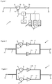
- Installation 1 Illustrated is an installation for recharging electric vehicles, referred to in the remainder of the description as installation 1.
- Installation 1 comprises a conduit 2, in which a fluid circulates which may be town gas or water.
- the installation 1 operates a network 200 for circulating an existing fluid which supplies homes and premises or buildings, businesses or others with fluid.
- This network 200 illustrated on the nonlimiting examples of figures 6 to 8 , can be a transport or distribution network of an external service provider or a network set up specifically for setting up the installation 1 which is the subject of the invention, or even for supplying other installations 100, for example an industrial site or a residential house.
- a draw-off point 201 is set up on the network 200, an inlet 2a of the pipe 2 of the installation 1 being connected to this draw-off point 201.
- the outlet 2b of the conduit 2 of the installation 1 can supply another installation 100.
- the network 200 may include an injection point 202 to which the outlet 2b of the conduit 2 is connected so as to reinject the fluid into the network 200 after having used the latter for the needs of the installation 1 object of the invention.
- the draw-off point 201 is disposed upstream of a pressure reducing valve 203 on the network 200 and the injection point 202 is arranged downstream of this pressure reducing valve 203.
- the installation 1 will be configured to keep at outlet 2b of the duct 2 a pressure slightly higher than the adjustment pressure of the regulator 203, so as to give priority in transmission to the installation 1 vis-à-vis the regulator 203.
- this pressure slightly higher than the regulating pressure of the regulator 203 allows the installation 1 to bypass the section of the network 200 located between the draw-off point 201 and the injection point 202.
- this pressure slightly higher than the regulating pressure of the regulator 203 allows the installation 1 to bypass the section of the network 200 located between the draw-off point 201 and the injection point 202.
- figure 8 one could however consider, as a variant, the implementation of the installation 1 directly on a network 200.
- Town gas is first transported in the network at a pressure of the order of 70 bars (sometimes 110 bars or 200 bars), then is successively reduced by means of regulators, for example to a pressure of the order of 35 to 40 bars and at a pressure of the order of 4 to 16 bars, which can then be distributed to direct customers.
- this pressure is reduced again at the level of the gas box of the hearths, to a pressure of the order of 21 to 25 millibars, this box generally incorporating a regulator and a meter.
- Drinking water can also be conveyed in stages by means of pressure reducers, to reach a pressure of the order of 1 to 4 bars at the household level.
- the initial pressure of the water is much less than in the case of gas, of the order of 10 bars.
- the installation 1 comprises an expansion valve 3 and a turbogenerator 4 which are installed on the pipe 2.
- the circulation of the fluid in the turbine (not shown) of the turbogenerator 4 makes it possible to generate electricity at the outlet 4a of the alternator (not illustrated) of said turbogenerator 4.
- the design of such a turbogenerator 4 is well known, which is why it is not detailed.
- the installation 1 comprises an electrical management cabinet, subsequently called cabinet 5, which is connected by means of a cable 6 to the outlet 4a of the turbogenerator 4.
- This cabinet 5 is connected to charging stations of electric vehicles, called then charging stations 7, via cables 8.
- charging stations 7 are illustrated, but their number may vary between one and ten, for example.
- Each charging station 7 comprises at least one socket 9 for connection to an electric vehicle (not shown) to be recharged.
- These charging stations 7 can be charging stations or boxes, as known, depending on the location (public charging stations or private garages).
- the installation 1 includes a battery 10 (or even several batteries 10, depending on the dimensioning of the installation 1) connected to the cabinet 5 by means of a cable 11.
- the cabinet 5 is configured to manage the temporary storage in the battery 10 of the electricity produced by the turbogenerator 4, then to restore this electricity stored in the battery 10 and distribute it to the charging station 7 when an electric vehicle is connected to the latter.
- the installation 1 comprises a regulator 3 making it possible to reduce the pressure of the fluid in the pipe 2.
- the regulator 3 can make it possible to reduce the pressure of the gas by a value of the order of 70 bars at the inlet 2a of the duct 2, to a value of the order of 35 to 40 bars at the outlet 2b of the said duct 2, or even can make it possible to reduce the gas pressure by a value of the order of 35 to 40 bars at inlet 2a, at a value of the order of bars 4 to 16 bars at outlet 2b.
- the positioning of the turbogenerator 4 upstream of the expansion valve 3 advantageously makes it possible to reduce the pressure of the fluid at the inlet 3a of said expansion valve 3.
- the turbogenerator 4 will be sized so that the pressure of the fluid at its outlet 4b is greater than the pressure at the outlet 3b of the expansion valve 3, for example of the order of 0.5 to 10 bars, preferably 0.5 to 3 bars .
- the pressure P 'at the outlet 4b of the turbogenerator 4 will be of the order of 38 bars, the pressure P ′′ of the fluid at the inlet 4c of the turbogenerator 4 being of the order of 70 bars.
- the pressure P ′ when the pressure P is of the order of 21 to 25 millibars, the pressure P ′ will be of the order of 0 , 5 bars for a pressure P "of the order of 4 bars.
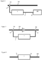
- FIG. 2 to 4 illustrate variants according to which the installation 1 is implemented on a duct 2 comprising a main line 12 and a secondary line 13 both mounted in parallel.
- Cabinet 5 battery 10 and charging stations 7 are not shown on the figures 2 and 3 , in order to alleviate these.
- the main line 12 comprises a regulator 14 set to deliver at its outlet 14b a pressure P1 and the secondary line 13 comprises a regulator 15 set to deliver at its outlet 15b a pressure P2 slightly lower than the pressure P1.
- the pressure P1 is 35 bars and the pressure P2 is 34 bars.
- the secondary line 13 takes over and the fluid begins to circulate in the conduit 2 passing through this secondary line 13.
- a turbogenerator 4 is installed upstream of the expansion valve 14 on the main line 12. While on the figure 3 , two turbogenerators 4 are installed upstream of the expansion valves 14, 15 respectively on the main line 12 and on the secondary line 13.
- the turbogenerator (s) 4 are connected to the cabinet 5, as in the case of the figure 1 .
- the main line 12 comprises, as above, a regulator 14 set to deliver a pressure P1.
- the regulator 15 on the secondary line 13 is provided with an adjustment system 16 making it possible to modify the pressure at the outlet 15b, in order to adjust this regulator 15 either to a pressure P2, lower than the pressure P1, or to a pressure P3, greater than pressure P1.
- the pressure P1 will be equal to 35 bars
- the pressure P2 will be equal to 34 bars
- the pressure P3 will be equal to 36 bars.
- the secondary line 13 is equipped with a turbogenerator 4 arranged upstream of the expansion valve 15.
- the cabinet 5 is connected to the adjustment system 16 by means of a cable 17, or even a transmitter / receiver (not illustrated) ensuring a radio frequency type remote connection.
- the line principal 12 takes the hand and ensures a circulation of the fluid.
- the secondary line 13 takes over, the turbogenerator 4 ensuring the recharging of the battery 10.
- the cabinet 5 is informed and acts on the adjustment system 16 of the pressure reducer 15 to adjust it to the pressure P3, which forces the hand and ensures the passage of the fluid in the secondary line 13, allowing the turbogenerator 4 to operate and to directly supply electric power to the activated charging station 7.
- the cabinet 5 is configured to manage the distribution of electricity to the battery 10 or to the charging station (s) 7 when they are activated.
- the conduit 2 comprises a ramp 18 with four lines 19 each equipped with a solenoid valve 20 and a turbogenerator 4.
- cabinet 5 battery 10 and charging stations 7 are not shown, but these will also be present.
- the solenoid valves 20 are connected to the cabinet 5 by cables 21 or even by a remote connection of the transmitter / receiver type (not illustrated).
- the cabinet 5 manages the control of the solenoid valves 20 as a function of the variations in the consumption of the fluid, in particular of the gas, which can sometimes vary greatly in each household according to the seasons and periods of the day.
- the installation 1 is implemented downstream of a meter 22 arranged on the conduit 2, which will generally be supplied by the distributor.
- a counter 22 can also be placed on the installation 1 in the case of figures 1 to 4 .
- a regulator 23 is arranged downstream of the ramp 18, on the figure 5 .
- the cabinet 5 will include the AC / DC converters (not shown) necessary to supply electrically the charging stations 7 or to recharge the batteries from the turbogenerator (s) 4.
- the installation 1 as illustrated according to the various embodiments of the figures 1 to 5 can be set up at any point of the networks 200 for circulating fluids of gas or water type.
- the installation 1 will simply take into account the pressures of the fluid on the network 200 for its sizing.
- the installation 1 when the installation 1 is implemented on the town gas or water distribution network 200 directly at the level of a home, where the fluid is at a pressure of the order of 4 bars in entry 2a, the installation 1 will include one or two charging stations 7 of the charging box type with a socket 9.
- the installation 1 is switched on. working on a section of the network 200 so as to have a fluid inlet 2a at a pressure of the order of 70 bars, it may have a much larger number of charging stations 7.
Landscapes
- Engineering & Computer Science (AREA)
- Power Engineering (AREA)
- Mechanical Engineering (AREA)
- Chemical & Material Sciences (AREA)
- Combustion & Propulsion (AREA)
- General Engineering & Computer Science (AREA)
- Transportation (AREA)
- Other Liquid Machine Or Engine Such As Wave Power Use (AREA)
- Control Of Eletrric Generators (AREA)
- Electric Propulsion And Braking For Vehicles (AREA)
Claims (11)
- Installation (1) zum Aufladen von Elektrofahrzeugen, umfassend mindestens eine Ladestation (7), die mit mindestens einem Steckdosensockel (9) versehen ist, der zum Anstecken eines Elektrofahrzeugs konfiguriert ist, einen Kanal (2) zum Zirkulieren eines Fluids, mindestens zwei Turbogeneratoren (4) die an den Kanal (2) angeschlossen sind, und die Erzeugung von Strom ermöglichen, und Stromverteilungsmittel (5, 10) die zur Stromversorgung der mindestens einen Ladestation (7) aus den mindestens zwei Turbogeneratoren (4) konfiguriert sind, wobei der Kanal (2) eine Leitung umfasst, die mit einem Druckminderer (3, 23) versehen ist, der es ermöglicht, den Druck des Fluids auf einen Druckwert P zu senken, dadurch gekennzeichnet, dass die mindestens zwei Turbogeneratoren (4) parallel auf einer Verteilungsrampe (18) stromaufwärts des Druckminderers in dieser Leitung montiert sind, und konfiguriert sind, um am Ausgang einen Druck des Fluids höher als den Druck P zu halten, wobei die Verteilungsrampe konfiguriert ist, um alle Turbogeneratoren oder einen Teil davon (4) in Abhängigkeit von den Fluidverbrauchsvariationen zu versorgen, wobei es Verwaltungsmittel (5, 20) ermöglichen, die Verteilungsrampe zu kontrollieren.
- Installation zum Aufladen (1) nach Anspruch 1, wobei die Rampe (18) Leitungen (19) umfasst, die parallel montiert sind, und jeweils mit einem Magnetventil (20) und einem Turbogenerator (4) ausgerüstet sind, wobei die Verwaltungsmittel einen Schrank (5) umfassen, der die Steuerung der Magnetventile (20) in Abhängigkeit von den Fluidverbrauchsvariationen verwaltet.
- Installation zum Aufladen (1) nach einem der Ansprüche 1 oder 2, wobei der Kanal (2) eine Hauptleitung (12) umfasst, die mit einem ersten Druckminderer (14) versehen ist, der konfiguriert ist, um den Druck des Fluids auf einen ersten Druckwert P1 zu senken, und eine Sekundärleitung (13), die parallel zur Hauptleitung montiert ist, wobei die Sekundärleitung mit einem zweiten Druckminderer (15) versehen ist, der konfiguriert ist, um den Druck des Fluids auf einen zweiten Druckwert P2, geringer als der erste Druckwert P1 zu senken, wobei eine Rampe (18) stromaufwärts des ersten Druckminderers (14) in der ersten Leitung (12) angeordnet ist, wobei die Turbogeneratoren (4) der Rampe (18) konfiguriert sind, um am Ausgang einen Druck des Fluids höher als den ersten Druckwert P1 zu halten.
- Installation zum Aufladen (1) nach Anspruch 3, wobei eine Rampe (18) stromaufwärts des zweiten Druckminderers (15) in der zweiten Leitung (13) angeordnet ist, wobei die Turbogeneratoren (4) dieser Rampe (18) konfiguriert sind, um am Ausgang einen Druck des Fluids höher als den zweiten Druckwert P2 zu halten.
- Installation zum Aufladen (1) nach einem der Ansprüche 1 oder 2, wobei der Kanal (2) eine Hauptleitung (12) umfasst, die mit einem ersten Druckminderer (14) versehen ist, der konfiguriert ist, um den Druck des Fluids auf einen ersten Druckwert P1 zu senken, und eine Sekundärleitung (13), die parallel zur Hauptleitung montiert ist, wobei die Sekundärleitung mit einem zweiten Druckminderer (15) versehen ist, der konfiguriert ist, um derart geregelt zu werden, um den Druck des Fluids entweder auf einen zweiten Druckwert P2, geringer als der erste Druckwert P1, oder auf einen dritten Druckwert P3, höher als der erste Druckwert P1 zu senken, wobei eine Rampe (18) stromaufwärts des zweiten Druckminderers (15) in der zweiten Leitung (13) angeordnet ist, wobei die Turbogeneratoren (4) dieser Rrampe (18) konfiguriert sind, um am Ausgang einen Druck des Fluids höher als den dritten Druckwert P3 zu halten.
- Installation zum Aufladen (1) nach Anspruch 5, welche Steuerungsmittel (5, 16) umfasst, die konfiguriert sind, um in eine Regelung des zweiten Druckminderers (15) einzuwirken, um den Druck des Fluids auf den zweiten Druckwert P2 zu senken, solange die mindestens eine Ladestation (7) nicht aktiviert ist, und den Druck des Fluids auf den dritten Druckwert P3 zu erhöhen, wenn mindestens eine Ladestation (7) aktiviert ist.
- Installation zum Aufladen (1) nach einem der Ansprüche 2 bis 7, wobei der Druck des Fluids stromaufwärts des oder der Druckminderer(s) (3, 14, 15, 23) einen Wert aufweist, der zwischen 3 bar und 70 bar enthalten ist, wobei die Turbogeneratoren (4) in Abhängigkeit von dem Wert dieses Druckes angepasst werden.
- Installation zum Aufladen (1) nach Anspruch 7 im Zusammenhang mit einem der Ansprüche 5 oder 6, wobei der Druck des Fluids stromaufwärts des Druckminderers (14, 15) in der Größenordnung von 70 bar ist, der erste Druckwert P1 in der Größenordnung von 35 bar ist, der zweite Druckwert P2 in der Größenordnung von 34 bar ist und der dritte Druckwert P3 in der Größenordnung von 36 bar ist.
- Installation zum Aufladen (1) nach einem der Ansprüche 1 bis 8, wobei das Fluid ein Gas ist.
- Installation zum Aufladen (1) nach einem der Ansprüche 1 bis 9, wobei der Kanal (2) einen Eingang (2a) umfasst, der an eine Entnahmestelle angeschlossen ist, die in einem Netz (200) zum Zirkulieren eines Fluids angeordnet ist.
- Installation zum Aufladen (1) nach Anspruch 10, wobei der Kanal (2) einen Ausgang (2a) umfasst, der an eine Injektionsstelle angeschlossen ist, die in einem Netz (200) zum Zirkulieren eines Fluids angeordnet ist.
Applications Claiming Priority (1)
| Application Number | Priority Date | Filing Date | Title |
|---|---|---|---|
| FR1760407A FR3073335B1 (fr) | 2017-11-06 | 2017-11-06 | Installation de recharge de vehicules electriques equipee d'une turbogeneratrice exploitant les reseaux de fluides |
Publications (2)
| Publication Number | Publication Date |
|---|---|
| EP3480915A1 EP3480915A1 (de) | 2019-05-08 |
| EP3480915B1 true EP3480915B1 (de) | 2021-07-07 |
Family
ID=62091939
Family Applications (1)
| Application Number | Title | Priority Date | Filing Date |
|---|---|---|---|
| EP18204393.5A Active EP3480915B1 (de) | 2017-11-06 | 2018-11-05 | Anlage zum wiederaufladen elektrischer fahrzeuge, ausgestattet mit einem den flüssigkeitsverteilnetzen ausnutzenden turbogenerator |
Country Status (3)
| Country | Link |
|---|---|
| EP (1) | EP3480915B1 (de) |
| FR (1) | FR3073335B1 (de) |
| MA (1) | MA50270A (de) |
Families Citing this family (1)
| Publication number | Priority date | Publication date | Assignee | Title |
|---|---|---|---|---|
| US20260066689A1 (en) * | 2024-03-08 | 2026-03-05 | Ev Anytime Llc | Strategic resilient generation of clean electric power |
Citations (1)
| Publication number | Priority date | Publication date | Assignee | Title |
|---|---|---|---|---|
| US20120274066A1 (en) * | 2011-04-29 | 2012-11-01 | Montgomery James Scott | In-pipe turbine |
Family Cites Families (6)
| Publication number | Priority date | Publication date | Assignee | Title |
|---|---|---|---|---|
| EP2022978A3 (de) * | 2007-08-08 | 2012-12-26 | Greenpower SRL | Mit einem Wassernetz verbindbare Leistungsgenerator |
| ZA200901070B (en) * | 2008-02-25 | 2009-06-24 | Van Blerk Coenraad Frederik | Electricity generating arrangement |
| DE102010045715A1 (de) * | 2010-09-16 | 2012-03-22 | Ksb Aktiengesellschaft | Ladevorrichtung für Elektrofahrzeuge |
| US9322389B2 (en) * | 2011-09-01 | 2016-04-26 | Chevron U.S.A. Inc. | Power generation in a tubular structure by way of electromagnetic induction |
| DE202011105407U1 (de) * | 2011-09-07 | 2011-11-25 | Daniel Reuter | Vorrichtung zur Druckminderung und Stromerzeugung in Rohrleitungen |
| KR101769080B1 (ko) * | 2016-02-23 | 2017-08-18 | 주식회사 금강이엔지 | 수도시설의 배관 내에 설치되는 감압장치를 이용한 발전시스템 |
-
2017
- 2017-11-06 FR FR1760407A patent/FR3073335B1/fr not_active Expired - Fee Related
-
2018
- 2018-11-05 MA MA050270A patent/MA50270A/fr unknown
- 2018-11-05 EP EP18204393.5A patent/EP3480915B1/de active Active
Patent Citations (1)
| Publication number | Priority date | Publication date | Assignee | Title |
|---|---|---|---|---|
| US20120274066A1 (en) * | 2011-04-29 | 2012-11-01 | Montgomery James Scott | In-pipe turbine |
Also Published As
| Publication number | Publication date |
|---|---|
| FR3073335A1 (fr) | 2019-05-10 |
| FR3073335B1 (fr) | 2019-10-04 |
| EP3480915A1 (de) | 2019-05-08 |
| MA50270A (fr) | 2019-05-08 |
Similar Documents
| Publication | Publication Date | Title |
|---|---|---|
| FR2894401A1 (fr) | Dispositif de controle d'une installation de production d'energie electrique et installation de production d'energie electrique mettant en oeuvre un tel dispositif | |
| EP2004489B1 (de) | Vorrichtung und verfahren zur notstromversorgung an bord eines flugzeugs | |
| WO2017025664A1 (fr) | Système auxiliaire de stockage et de fourniture d'énergie électrique à usages multiples intégré à une centrale de production d'électricité | |
| EP3676541B1 (de) | Heizgerät mit einer batterie und einem wechselrichter zum zuführen von energie von der batterie in die elektrische versorgungsquelle | |
| EP2324552A1 (de) | Photovoltaiksystem mit integrierter photovoltaiktafel und batterie | |
| EP3480915B1 (de) | Anlage zum wiederaufladen elektrischer fahrzeuge, ausgestattet mit einem den flüssigkeitsverteilnetzen ausnutzenden turbogenerator | |
| WO2021069509A1 (fr) | Dispositif electrique de gestion energetique | |
| WO2020070438A1 (fr) | Architecture électrique pour propulsion hybride | |
| EP2149760B1 (de) | System zur Stromversorgung und -steuerung für eine thermodynamische Vorrichtung | |
| EP2073340A2 (de) | Stromversorgungssystem für Satelliten | |
| FR2924481A1 (fr) | Distributeur securise d'eau et/ou d'air pour systeme d'enneigement, equipe d'une vanne pilotee par un actionneur electrique | |
| EP3545724A1 (de) | Heizvorrichtung vom typ eines elektrischen heizkörpers mit einem spannungswandler | |
| BE1022140B1 (fr) | Systeme d'alimentation electrique sans coupure | |
| EP2859647B1 (de) | Mobil notstromaggregat | |
| FR3099208A1 (fr) | Circuit de carburant pour une turbomachine d’aeronef | |
| EP2533391B1 (de) | Multi-Source-Steuerungssystem von Stromgeneratoren | |
| WO2014096739A1 (fr) | Gestion de batteries haute temperature | |
| FR2944835A1 (fr) | Dispositif de production d'electricite a partir d'une source motrice a vitesse variable, et dispositif de stockage inertiel d'energie et eolienne ainsi equipees | |
| FR3068530A1 (fr) | Procede de distribution d'une energie electrique issue d'une energie solaire a une pluralite de groupes d'au moins une installation electrique | |
| WO2014020241A2 (fr) | Installation de production d'energie | |
| EP3273170B1 (de) | Anlage zur heisswasserbereitung mit einem thermodynamischen schaltkreis, der über fotovoltaikzellen gespeist wird | |
| WO2014095119A1 (fr) | Systeme de secours pour moteur | |
| WO2012001281A1 (fr) | Station de remplacement de batteries electriques de vehicules automobiles | |
| FR3150155A1 (fr) | Procédé de gestion d’un ensemble électrique | |
| FR3137805A1 (fr) | Dispositif de fourniture d’électricité adapté à maintenir l’inertie d’un système électrique |
Legal Events
| Date | Code | Title | Description |
|---|---|---|---|
| PUAI | Public reference made under article 153(3) epc to a published international application that has entered the european phase |
Free format text: ORIGINAL CODE: 0009012 |
|
| STAA | Information on the status of an ep patent application or granted ep patent |
Free format text: STATUS: THE APPLICATION HAS BEEN PUBLISHED |
|
| AK | Designated contracting states |
Kind code of ref document: A1 Designated state(s): AL AT BE BG CH CY CZ DE DK EE ES FI FR GB GR HR HU IE IS IT LI LT LU LV MC MK MT NL NO PL PT RO RS SE SI SK SM TR |
|
| AX | Request for extension of the european patent |
Extension state: BA ME |
|
| STAA | Information on the status of an ep patent application or granted ep patent |
Free format text: STATUS: REQUEST FOR EXAMINATION WAS MADE |
|
| 17P | Request for examination filed |
Effective date: 20191106 |
|
| RAV | Requested validation state of the european patent: fee paid |
Extension state: TN Effective date: 20191106 Extension state: MA Effective date: 20191106 |
|
| RBV | Designated contracting states (corrected) |
Designated state(s): AL AT BE BG CH CY CZ DE DK EE ES FI FR GB GR HR HU IE IS IT LI LT LU LV MC MK MT NL NO PL PT RO RS SE SI SK SM TR |
|
| STAA | Information on the status of an ep patent application or granted ep patent |
Free format text: STATUS: EXAMINATION IS IN PROGRESS |
|
| 17Q | First examination report despatched |
Effective date: 20191218 |
|
| RIC1 | Information provided on ipc code assigned before grant |
Ipc: H02J 7/32 20060101ALN20200619BHEP Ipc: B60L 53/50 20190101AFI20200619BHEP Ipc: F03B 13/00 20060101ALI20200619BHEP Ipc: H02J 7/34 20060101ALI20200619BHEP Ipc: H02J 7/00 20060101ALI20200619BHEP |
|
| RIC1 | Information provided on ipc code assigned before grant |
Ipc: F03B 13/00 20060101ALI20200716BHEP Ipc: H02J 7/34 20060101ALI20200716BHEP Ipc: B60L 53/50 20190101AFI20200716BHEP Ipc: H02J 7/32 20060101ALN20200716BHEP Ipc: H02J 7/00 20060101ALI20200716BHEP |
|
| GRAP | Despatch of communication of intention to grant a patent |
Free format text: ORIGINAL CODE: EPIDOSNIGR1 |
|
| STAA | Information on the status of an ep patent application or granted ep patent |
Free format text: STATUS: GRANT OF PATENT IS INTENDED |
|
| INTG | Intention to grant announced |
Effective date: 20200903 |
|
| GRAS | Grant fee paid |
Free format text: ORIGINAL CODE: EPIDOSNIGR3 |
|
| GRAJ | Information related to disapproval of communication of intention to grant by the applicant or resumption of examination proceedings by the epo deleted |
Free format text: ORIGINAL CODE: EPIDOSDIGR1 |
|
| GRAL | Information related to payment of fee for publishing/printing deleted |
Free format text: ORIGINAL CODE: EPIDOSDIGR3 |
|
| STAA | Information on the status of an ep patent application or granted ep patent |
Free format text: STATUS: EXAMINATION IS IN PROGRESS |
|
| REG | Reference to a national code |
Ref country code: DE Ref legal event code: R079 Ref document number: 602018019625 Country of ref document: DE Free format text: PREVIOUS MAIN CLASS: H02J0007000000 Ipc: B60L0053500000 |
|
| GRAP | Despatch of communication of intention to grant a patent |
Free format text: ORIGINAL CODE: EPIDOSNIGR1 |
|
| STAA | Information on the status of an ep patent application or granted ep patent |
Free format text: STATUS: GRANT OF PATENT IS INTENDED |
|
| INTC | Intention to grant announced (deleted) | ||
| RIC1 | Information provided on ipc code assigned before grant |
Ipc: B60L 53/50 20190101AFI20210118BHEP Ipc: H02J 7/32 20060101ALN20210118BHEP Ipc: H02J 7/34 20060101ALI20210118BHEP Ipc: H02J 7/00 20060101ALI20210118BHEP Ipc: F03B 13/00 20060101ALI20210118BHEP |
|
| INTG | Intention to grant announced |
Effective date: 20210204 |
|
| GRAA | (expected) grant |
Free format text: ORIGINAL CODE: 0009210 |
|
| STAA | Information on the status of an ep patent application or granted ep patent |
Free format text: STATUS: THE PATENT HAS BEEN GRANTED |
|
| AK | Designated contracting states |
Kind code of ref document: B1 Designated state(s): AL AT BE BG CH CY CZ DE DK EE ES FI FR GB GR HR HU IE IS IT LI LT LU LV MC MK MT NL NO PL PT RO RS SE SI SK SM TR |
|
| REG | Reference to a national code |
Ref country code: GB Ref legal event code: FG4D Free format text: NOT ENGLISH |
|
| REG | Reference to a national code |
Ref country code: AT Ref legal event code: REF Ref document number: 1408252 Country of ref document: AT Kind code of ref document: T Effective date: 20210715 |
|
| REG | Reference to a national code |
Ref country code: DE Ref legal event code: R096 Ref document number: 602018019625 Country of ref document: DE |
|
| REG | Reference to a national code |
Ref country code: IE Ref legal event code: FG4D Free format text: LANGUAGE OF EP DOCUMENT: FRENCH |
|
| REG | Reference to a national code |
Ref country code: LT Ref legal event code: MG9D |
|
| REG | Reference to a national code |
Ref country code: NL Ref legal event code: MP Effective date: 20210707 |
|
| REG | Reference to a national code |
Ref country code: AT Ref legal event code: MK05 Ref document number: 1408252 Country of ref document: AT Kind code of ref document: T Effective date: 20210707 |
|
| PG25 | Lapsed in a contracting state [announced via postgrant information from national office to epo] |
Ref country code: AT Free format text: LAPSE BECAUSE OF FAILURE TO SUBMIT A TRANSLATION OF THE DESCRIPTION OR TO PAY THE FEE WITHIN THE PRESCRIBED TIME-LIMIT Effective date: 20210707 Ref country code: BG Free format text: LAPSE BECAUSE OF FAILURE TO SUBMIT A TRANSLATION OF THE DESCRIPTION OR TO PAY THE FEE WITHIN THE PRESCRIBED TIME-LIMIT Effective date: 20211007 Ref country code: LT Free format text: LAPSE BECAUSE OF FAILURE TO SUBMIT A TRANSLATION OF THE DESCRIPTION OR TO PAY THE FEE WITHIN THE PRESCRIBED TIME-LIMIT Effective date: 20210707 Ref country code: PT Free format text: LAPSE BECAUSE OF FAILURE TO SUBMIT A TRANSLATION OF THE DESCRIPTION OR TO PAY THE FEE WITHIN THE PRESCRIBED TIME-LIMIT Effective date: 20211108 Ref country code: NL Free format text: LAPSE BECAUSE OF FAILURE TO SUBMIT A TRANSLATION OF THE DESCRIPTION OR TO PAY THE FEE WITHIN THE PRESCRIBED TIME-LIMIT Effective date: 20210707 Ref country code: NO Free format text: LAPSE BECAUSE OF FAILURE TO SUBMIT A TRANSLATION OF THE DESCRIPTION OR TO PAY THE FEE WITHIN THE PRESCRIBED TIME-LIMIT Effective date: 20211007 Ref country code: ES Free format text: LAPSE BECAUSE OF FAILURE TO SUBMIT A TRANSLATION OF THE DESCRIPTION OR TO PAY THE FEE WITHIN THE PRESCRIBED TIME-LIMIT Effective date: 20210707 Ref country code: FI Free format text: LAPSE BECAUSE OF FAILURE TO SUBMIT A TRANSLATION OF THE DESCRIPTION OR TO PAY THE FEE WITHIN THE PRESCRIBED TIME-LIMIT Effective date: 20210707 Ref country code: HR Free format text: LAPSE BECAUSE OF FAILURE TO SUBMIT A TRANSLATION OF THE DESCRIPTION OR TO PAY THE FEE WITHIN THE PRESCRIBED TIME-LIMIT Effective date: 20210707 Ref country code: RS Free format text: LAPSE BECAUSE OF FAILURE TO SUBMIT A TRANSLATION OF THE DESCRIPTION OR TO PAY THE FEE WITHIN THE PRESCRIBED TIME-LIMIT Effective date: 20210707 Ref country code: SE Free format text: LAPSE BECAUSE OF FAILURE TO SUBMIT A TRANSLATION OF THE DESCRIPTION OR TO PAY THE FEE WITHIN THE PRESCRIBED TIME-LIMIT Effective date: 20210707 |
|
| PGFP | Annual fee paid to national office [announced via postgrant information from national office to epo] |
Ref country code: IE Payment date: 20211125 Year of fee payment: 4 |
|
| PG25 | Lapsed in a contracting state [announced via postgrant information from national office to epo] |
Ref country code: PL Free format text: LAPSE BECAUSE OF FAILURE TO SUBMIT A TRANSLATION OF THE DESCRIPTION OR TO PAY THE FEE WITHIN THE PRESCRIBED TIME-LIMIT Effective date: 20210707 Ref country code: LV Free format text: LAPSE BECAUSE OF FAILURE TO SUBMIT A TRANSLATION OF THE DESCRIPTION OR TO PAY THE FEE WITHIN THE PRESCRIBED TIME-LIMIT Effective date: 20210707 Ref country code: GR Free format text: LAPSE BECAUSE OF FAILURE TO SUBMIT A TRANSLATION OF THE DESCRIPTION OR TO PAY THE FEE WITHIN THE PRESCRIBED TIME-LIMIT Effective date: 20211008 |
|
| REG | Reference to a national code |
Ref country code: DE Ref legal event code: R097 Ref document number: 602018019625 Country of ref document: DE |
|
| PG25 | Lapsed in a contracting state [announced via postgrant information from national office to epo] |
Ref country code: DK Free format text: LAPSE BECAUSE OF FAILURE TO SUBMIT A TRANSLATION OF THE DESCRIPTION OR TO PAY THE FEE WITHIN THE PRESCRIBED TIME-LIMIT Effective date: 20210707 |
|
| PLBE | No opposition filed within time limit |
Free format text: ORIGINAL CODE: 0009261 |
|
| STAA | Information on the status of an ep patent application or granted ep patent |
Free format text: STATUS: NO OPPOSITION FILED WITHIN TIME LIMIT |
|
| PG25 | Lapsed in a contracting state [announced via postgrant information from national office to epo] |
Ref country code: SM Free format text: LAPSE BECAUSE OF FAILURE TO SUBMIT A TRANSLATION OF THE DESCRIPTION OR TO PAY THE FEE WITHIN THE PRESCRIBED TIME-LIMIT Effective date: 20210707 Ref country code: SK Free format text: LAPSE BECAUSE OF FAILURE TO SUBMIT A TRANSLATION OF THE DESCRIPTION OR TO PAY THE FEE WITHIN THE PRESCRIBED TIME-LIMIT Effective date: 20210707 Ref country code: RO Free format text: LAPSE BECAUSE OF FAILURE TO SUBMIT A TRANSLATION OF THE DESCRIPTION OR TO PAY THE FEE WITHIN THE PRESCRIBED TIME-LIMIT Effective date: 20210707 Ref country code: EE Free format text: LAPSE BECAUSE OF FAILURE TO SUBMIT A TRANSLATION OF THE DESCRIPTION OR TO PAY THE FEE WITHIN THE PRESCRIBED TIME-LIMIT Effective date: 20210707 Ref country code: CZ Free format text: LAPSE BECAUSE OF FAILURE TO SUBMIT A TRANSLATION OF THE DESCRIPTION OR TO PAY THE FEE WITHIN THE PRESCRIBED TIME-LIMIT Effective date: 20210707 Ref country code: AL Free format text: LAPSE BECAUSE OF FAILURE TO SUBMIT A TRANSLATION OF THE DESCRIPTION OR TO PAY THE FEE WITHIN THE PRESCRIBED TIME-LIMIT Effective date: 20210707 |
|
| 26N | No opposition filed |
Effective date: 20220408 |
|
| PG25 | Lapsed in a contracting state [announced via postgrant information from national office to epo] |
Ref country code: MC Free format text: LAPSE BECAUSE OF FAILURE TO SUBMIT A TRANSLATION OF THE DESCRIPTION OR TO PAY THE FEE WITHIN THE PRESCRIBED TIME-LIMIT Effective date: 20210707 |
|
| REG | Reference to a national code |
Ref country code: CH Ref legal event code: PL |
|
| PG25 | Lapsed in a contracting state [announced via postgrant information from national office to epo] |
Ref country code: LU Free format text: LAPSE BECAUSE OF NON-PAYMENT OF DUE FEES Effective date: 20211105 Ref country code: IT Free format text: LAPSE BECAUSE OF FAILURE TO SUBMIT A TRANSLATION OF THE DESCRIPTION OR TO PAY THE FEE WITHIN THE PRESCRIBED TIME-LIMIT Effective date: 20210707 |
|
| PG25 | Lapsed in a contracting state [announced via postgrant information from national office to epo] |
Ref country code: CY Free format text: LAPSE BECAUSE OF FAILURE TO SUBMIT A TRANSLATION OF THE DESCRIPTION OR TO PAY THE FEE WITHIN THE PRESCRIBED TIME-LIMIT Effective date: 20210707 |
|
| GBPC | Gb: european patent ceased through non-payment of renewal fee |
Effective date: 20221105 |
|
| PG25 | Lapsed in a contracting state [announced via postgrant information from national office to epo] |
Ref country code: LI Free format text: LAPSE BECAUSE OF NON-PAYMENT OF DUE FEES Effective date: 20220630 Ref country code: HU Free format text: LAPSE BECAUSE OF FAILURE TO SUBMIT A TRANSLATION OF THE DESCRIPTION OR TO PAY THE FEE WITHIN THE PRESCRIBED TIME-LIMIT; INVALID AB INITIO Effective date: 20181105 Ref country code: CH Free format text: LAPSE BECAUSE OF NON-PAYMENT OF DUE FEES Effective date: 20220630 |
|
| PG25 | Lapsed in a contracting state [announced via postgrant information from national office to epo] |
Ref country code: IE Free format text: LAPSE BECAUSE OF NON-PAYMENT OF DUE FEES Effective date: 20221105 Ref country code: GB Free format text: LAPSE BECAUSE OF NON-PAYMENT OF DUE FEES Effective date: 20221105 |
|
| PG25 | Lapsed in a contracting state [announced via postgrant information from national office to epo] |
Ref country code: MK Free format text: LAPSE BECAUSE OF FAILURE TO SUBMIT A TRANSLATION OF THE DESCRIPTION OR TO PAY THE FEE WITHIN THE PRESCRIBED TIME-LIMIT Effective date: 20210707 |
|
| VS25 | Lapsed in a validation state [announced via postgrant information from nat. office to epo] |
Ref country code: MA Free format text: LAPSE BECAUSE OF FAILURE TO SUBMIT A TRANSLATION OF THE DESCRIPTION OR TO PAY THE FEE WITHIN THE PRESCRIBED TIME-LIMIT Effective date: 20210707 |
|
| PG25 | Lapsed in a contracting state [announced via postgrant information from national office to epo] |
Ref country code: TR Free format text: LAPSE BECAUSE OF FAILURE TO SUBMIT A TRANSLATION OF THE DESCRIPTION OR TO PAY THE FEE WITHIN THE PRESCRIBED TIME-LIMIT Effective date: 20210707 |
|
| PG25 | Lapsed in a contracting state [announced via postgrant information from national office to epo] |
Ref country code: MT Free format text: LAPSE BECAUSE OF FAILURE TO SUBMIT A TRANSLATION OF THE DESCRIPTION OR TO PAY THE FEE WITHIN THE PRESCRIBED TIME-LIMIT Effective date: 20210707 |
|
| PGFP | Annual fee paid to national office [announced via postgrant information from national office to epo] |
Ref country code: DE Payment date: 20241121 Year of fee payment: 7 |
|
| PGFP | Annual fee paid to national office [announced via postgrant information from national office to epo] |
Ref country code: BE Payment date: 20241120 Year of fee payment: 7 |
|
| PGFP | Annual fee paid to national office [announced via postgrant information from national office to epo] |
Ref country code: FR Payment date: 20250618 Year of fee payment: 8 |