EP3939797A1 - Etikettendrucker - Google Patents
Etikettendrucker Download PDFInfo
- Publication number
- EP3939797A1 EP3939797A1 EP20185815.6A EP20185815A EP3939797A1 EP 3939797 A1 EP3939797 A1 EP 3939797A1 EP 20185815 A EP20185815 A EP 20185815A EP 3939797 A1 EP3939797 A1 EP 3939797A1
- Authority
- EP
- European Patent Office
- Prior art keywords
- label printer
- locking
- housing element
- tape cassette
- printer according
- Prior art date
- Legal status (The legal status is an assumption and is not a legal conclusion. Google has not performed a legal analysis and makes no representation as to the accuracy of the status listed.)
- Granted
Links
Images


Classifications
-
- B—PERFORMING OPERATIONS; TRANSPORTING
- B41—PRINTING; LINING MACHINES; TYPEWRITERS; STAMPS
- B41J—TYPEWRITERS; SELECTIVE PRINTING MECHANISMS, i.e. MECHANISMS PRINTING OTHERWISE THAN FROM A FORME; CORRECTION OF TYPOGRAPHICAL ERRORS
- B41J15/00—Devices or arrangements of selective printing mechanisms, e.g. ink-jet printers or thermal printers, specially adapted for supporting or handling copy material in continuous form, e.g. webs
- B41J15/04—Supporting, feeding, or guiding devices; Mountings for web rolls or spindles
- B41J15/044—Cassettes or cartridges containing continuous copy material, tape, for setting into printing devices
-
- B—PERFORMING OPERATIONS; TRANSPORTING
- B41—PRINTING; LINING MACHINES; TYPEWRITERS; STAMPS
- B41J—TYPEWRITERS; SELECTIVE PRINTING MECHANISMS, i.e. MECHANISMS PRINTING OTHERWISE THAN FROM A FORME; CORRECTION OF TYPOGRAPHICAL ERRORS
- B41J3/00—Typewriters or selective printing or marking mechanisms characterised by the purpose for which they are constructed
- B41J3/407—Typewriters or selective printing or marking mechanisms characterised by the purpose for which they are constructed for marking on special material
- B41J3/4075—Tape printers; Label printers
-
- G—PHYSICS
- G01—MEASURING; TESTING
- G01G—WEIGHING
- G01G19/00—Weighing apparatus or methods adapted for special purposes not provided for in the preceding groups
- G01G19/40—Weighing apparatus or methods adapted for special purposes not provided for in the preceding groups with provisions for indicating, recording, or computing price or other quantities dependent on the weight
- G01G19/413—Weighing apparatus or methods adapted for special purposes not provided for in the preceding groups with provisions for indicating, recording, or computing price or other quantities dependent on the weight using electromechanical or electronic computing means
- G01G19/414—Weighing apparatus or methods adapted for special purposes not provided for in the preceding groups with provisions for indicating, recording, or computing price or other quantities dependent on the weight using electromechanical or electronic computing means using electronic computing means only
- G01G19/4144—Weighing apparatus or methods adapted for special purposes not provided for in the preceding groups with provisions for indicating, recording, or computing price or other quantities dependent on the weight using electromechanical or electronic computing means using electronic computing means only for controlling weight of goods in commercial establishments, e.g. supermarket, P.O.S. systems
Definitions
- the invention relates to a label printer for printing endless tape labels wound on a roll, applied to a carrier tape or without a carrier, with a housing in which a cassette compartment is formed, a tape cassette with at least one unwinding mandrel, in which a label roll can be accommodated and which is manually the cassette compartment can be inserted and removed from the cassette compartment, and a print head and a driven print roller, the label tape, ie the carrier tape or the endless tape, of the label roll being able to be passed between the print head and the print roller.
- the label roll itself must be handled and placed on an unwinding mandrel in the housing, and the beginning of the label tape must be correctly inserted into the label printer.
- the start of the label tape In the case of a carrier tape, the start of the label tape must be threaded into a winding mandrel. This is not necessary when using tape cassettes that are easier to handle, so that label rolls can be changed more easily, quickly and easily. However, it is necessary that the tape cassette be securely held in the set position to prevent the label printer from malfunctioning.
- the invention is based on the object of specifying a label printer of the type mentioned at the outset, in which the tape cassette can be held securely in the inserted position and at the same time can be changed in a user-friendly manner.
- a label printer having the features of claim 1, and in particular in that the cassette compartment has a spring device and a movable, with a spring force of the spring device in a detent position prestressed detent holder for the tape cassette are assigned, wherein the tape cassette can be locked into the detent holder when inserted against the spring force and can be disengaged from the detent holder when removed.
- the spring force of the spring device must therefore be overcome both when inserting and when removing the tape cassette.
- the locking mechanism according to the invention allows the tape cassette to be held securely in the inserted position and, on the other hand, to be inserted into the cassette compartment and removed from the cassette compartment without any particular effort, with just one movement and thus in a user-friendly manner. There is no need for a latch to hold the tape cartridge in the inserted position, which would need to be released before the tape cartridge can be removed from the inserted position. The operator therefore does not have to press a button, handle or the like in order to be able to remove the tape cassette.
- the force that the operator must exert to engage and disengage the tape cassette can be specified via the selected spring rate of the spring device.
- the tape cassette presses against the latching mount during insertion and removal in such a way that the latching mount is temporarily pushed out of the latching position against the spring force in order to allow latching and unlatching.
- the latching holder initially deflects against the spring force of the spring device and is then pushed back into the latched position as soon as the tape cassette has reached the inserted position or has been removed sufficiently far.
- the locking holder can have a contact section with two ramps, the tape cassette being inserted against the one ramp and presses against the other ramp when removing.
- the locking mechanism can be implemented in a simple manner.
- the two ramps each run obliquely to the direction of movement of the locking bracket out of the locking position.
- the two ramps do not have to be strictly linear, ie it is not necessary for the respective ramp to have a constant positive or negative slope.
- the two ramps can together form a V-shape in a plane that is defined by the direction of movement of the latching mount out of the latched position and the direction of movement of the tape cassette during insertion and removal.
- the two ramps converge and together form a tip of the contact section. This enables fast and defined switching between the engaged position and the disengaged position of the tape cassette.
- the movable latching mount is preferably designed as a latching mount that can be pivoted about a pivot axis, in particular as a pivotable latching arm.
- the locking holder it is also possible for the locking holder to be able to be moved linearly out of the locking position.
- a pivot bearing can be implemented comparatively easily compared to a linear guide.
- the spring device can be a torsion spring, which preloads the pivotable latching mount into the latching position.
- a torsion spring is particularly well suited for realizing a preload in a pivot bearing.
- one such spring device and one such locking bracket are provided.
- the two locking brackets can be rigidly coupled to one another or can be moved independently of one another.
- the pressure roller can be part of the tape cassette.
- the print roller is thus removed from the housing with each label roll change together with the tape cassette. If necessary, the print roller can be replaced more easily from the removed tape cassette than from the label printer housing. This is particularly advantageous when changing from labels applied to a carrier tape to labels without a carrier tape or vice versa, since the print roller is then usually also changed, since a print roller for labels without a carrier tape usually consists of a different material than a print roller for labels applied to a carrier tape. It is preferred if the pressure roller can be replaced without tools. This can be achieved in particular in that pivot bearings of the pressure roller are accommodated in corresponding recesses of the tape cassette, forming a press fit that can be released by hand.
- the tape cassette engages with a respective axial end of the axis of the pressure roller in the respective latching mount and disengages from the respective latching mount.
- the print roller is fixed directly and can be held in a precisely defined position relative to the print head of the label printer.
- the respective latching mount engages at a point other than the respective axial end of the pressure roller.
- One or two snap-in mounts can be provided.
- a housing element in particular a door, that can be folded between a closed position and an open position about an axis of rotation is attached to the housing, which, in particular, enables access to the cassette compartment for inserting and removing the tape cassette in the open position and prevented in the closed position.
- the tape cassette can therefore only be inserted or removed when the housing element is open.
- the print head and the print roller are dust-protected inside the housing.
- a holding device is preferably provided in order to hold the housing element in the closed position on the housing.
- the holding device can, for example, have a lock that must be released before the housing element can be folded back into the open position.
- only one magnet holder is preferably provided on the housing to hold the housing element in the closed position. The housing element can thus be folded directly into the open position, simply by overcoming the magnetic force of the magnetic holder, without a locking device having to be released beforehand. Such an opening is very convenient for an operator.
- the housing element is provided with a safety device which, when the housing element is in the closed position, blocks a movement of the latching mount out of the latching position.
- rotating components can generate forces that act at least with a component in the direction of movement of the tape cassette out of the latched position. This can be the case, in particular, when the label printer is operated with linerless endless tape labels and the print roller is part of the tape cassette.
- a cutter is required downstream of the print head and the pressure roller, with which the printed label is separated from the endless tape.
- the endless belt is fed up to the beginning of the label of the next label, at which the previous label was severed, withdrawn (reversing).
- the pressure roller is operated in the opposite direction of rotation, as a result of which the aforementioned forces can arise.
- these forces can be counteracted by a spring device with a high spring hardness.
- inserting and removing the tape cassette is then made more difficult for the operator and thus uncomfortable.
- These forces can also be counteracted with the fuse without a particularly high spring rate of the spring device being required.
- the safety device becomes effective automatically simply by closing the housing element, ie the safety device does not have to be actuated separately for this purpose.
- the fuse can have a blocking element provided on an inner side of the housing element, in the closed position of the housing element with a free end protruding in the direction of the latching mount, which has a blocking effect on the latching mount in the closed position of the housing element.
- the blocking element In the closed position of the housing element, the blocking element preferably lies directly, i.e. not indirectly via one or more other force-transmitting components, on the latching mount.
- the structure can be kept particularly simple and consequently less susceptible to faults.
- a force acting on the latching mount in the direction of a movement out of the latched position acts on the blocking element in such a way that no torque is exerted on the foldable housing element.
- This can ensure that a force acting on the locking bracket in the direction of a movement out of the locking position is completely dissipated in the pivot bearing of the housing element and thus under no circumstances, not even with high forces, for example in the event of a significant malfunction could occur, can lead to an opening movement of the housing element.
- a magnetic holder is used as the holding device to hold the housing element in the closed position on the housing, the magnetic holder only having to have a low magnetic force, so that the housing element can be operated particularly conveniently.
- the fact that no torque is exerted on the foldable housing element can be achieved in particular by the fact that the direction of movement of the locking bracket out of the locking position is parallel to the radial extension of the foldable housing element in the closed position of the housing element and/or perpendicular to the free end of the locking element is oriented in the closed position of the housing element.
- the blocking element is preferably manufactured as a stamped and bent part made of sheet metal.
- a stamped and bent part can be manufactured inexpensively and simply screwed onto the inside of the housing element. The backup can thus be implemented with simple means and without high costs.
- the present invention also relates to scales, in particular retail scales, with a label printer as explained above.
- the 1 exemplary scales 11 shown in particular retail scales, includes a load plate 13, which determines the weight of an item lying on it, which is displayed both on a display 15 for the customer and on a display 17 for the seller.
- the display 17 is in the form of a touch screen, so that the scales 11 can also be operated via this.
- An identification number (PLU) assigned to the respective article can be entered via the touchscreen 17, so that, with the addition of the weight Price can be calculated for the item, which is then also displayed on the two ads 15, 17.
- the retail scale includes a label printer 19 for printing a label with the weight, the name of the item and the price charged.
- the label printer 19 is in the Figures 2 to 5 each shown in an individual representation and in a plan view.
- the label printer 19 comprises a housing 21 in which a cassette compartment 23 is formed, in which a tape cassette 25 (cf Figures 3 to 5 ) can be used.
- a hinged on the housing 21 about an axis of rotation mounted housing element 27 is provided in the form of a door between a in the Figures 2 to 4 shown open position and an in figure 5 shown closed position is adjustable.
- the label printer 19 can be operated with labels applied to a carrier tape, which are wound onto a roll and thus accommodated in the tape cassette 25 as a label roll.
- the label roll is placed on an unwinding mandrel 29 of the tape cassette 25, which is vertically oriented when the label printer 19 is in the operating position, from which the label tape is unwound when the label printer 19 is in operation.
- the tape cassette 25 has a driven winding mandrel 31 for the unwound carrier tape.
- a print head 33 and a driven pressure roller 35 cooperating with the print head 33 are provided.
- the print head 33 is arranged in the housing 21 .
- the pressure roller 35 is part of the tape cassette 25.
- the pressure roller 35 is in each case at its two axial ends stored in a separate pivot bearing, which are pressed positively and non-positively, but releasably, into corresponding recesses of the tape cassette 25, so that the pressure roller 35 can be replaced without tools.
- the pressure roller 35 and the take-up mandrel 31 are connected via a gear train, from which in 3 a gear wheel 37 can be seen, driven by an electric motor 39 of the label printer 19.
- the tape cassette 25 thus does not have its own electric motor.
- the carrier tape 41 with the labels is guided between the print head 33 and the print roller 35 in order to print the labels, as is shown in figure 5 is indicated schematically. After the printing area, the carrier tape 41 is wrapped around a dispensing edge 43 (cf. 3 ) is sharply deflected so that the labels can peel off and be ejected from the label printer 19, as indicated by an arrow 45 in figure 5 is illustrated.
- the label printer 19 can also be operated with carrierless endless tape labels, which are also referred to as linerless labels.
- a winding mandrel is not required for linerless endless tape labels.
- this requires a cutter which is arranged behind the print head 33 and the pressure roller 35 and with which the labels are cut off from the endless belt.
- Such a cutter is in the Figures 2 to 5 then in the lower right corner of the housing 21 of the label printer 19, wherein the in 1 housing corner section 61 shown is then exchanged for a corresponding housing corner section with the cutter.
- a latching mechanism is provided in which the tape cassette 25 can be latched into the inserted position against a spring force during insertion and can be disengaged from the inserted position against the spring force during removal.
- the cassette compartment 23 has at least one snap-in mount that can be pivoted about a pivot axis 47 associated in the form of a locking arm, by an associated spring device 49 in the form of a torsion spring in a locking position in which Figures 2 to 5 counterclockwise, is biased.
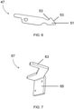
- the locking holder 47 acts via a contact section 51 provided on the free end of the locking holder 47 (cf. in particular 6 ) with one of the two axial ends of the pressure roller 35 or the axis of the pressure roller 35 together.
- the contact section 51 which is prestressed by means of the spring device 49 in the direction of the path along which the tape cassette 25 is inserted into the cassette compartment 23 or removed from the cassette compartment 23, has two ramps 53 which converge in a V-shape in the pivoting plane of the locking bracket 47. In the 2 and 3 ie if the tape cassette 25 is not or only partially inserted into the cassette compartment 23, the contact section 51 with the tip formed by the two ramps 53 projects into the aforementioned track.
- the axial end of the axis of the pressure roller 35 presses against the Figures 2 to 5 right ramp 53 of the contact portion 51, so that the locking bracket 47 against the spring force of the spring means 49, in the Figures 2 to 5 clockwise, is temporarily pushed out of the detent position.
- the locking bracket 47 and thus the contact section 51 is pushed back into the locking position and the axial end of the axis of the pressure roller 35 locks behind the contact section 51 (cf 4 and 5 ).
- the removal of the tape cassette 25 is analogous in the reverse direction, in which case the axial end of the axis of the pressure roller 35 against the in the Figures 2 to 5 left ramp 53 of the contact portion 51 presses.
- an arrangement as described above with the latching bracket 47 and the spring device 49 not only engages in the Figures 2 to 5 visible axial end of the axis of the pressure roller 35, but on both axial ends, ie a total of two such locking brackets 47 and two such spring devices 49 are provided.
- the two locking brackets 47 can be rigidly coupled to one another or can be moved independently of one another.
- a safety device 55 is provided, with which, when the housing element 27 is in the closed position, a pivoting movement of the latching holder 47 out of the latching position can be blocked.
- the fuse 55 comprises a blocking element 57 which, in the closed position of the housing element 27, has a free end 63 (cf. in particular 7 ) protrudes in the direction of the latching bracket 47 and is in direct contact with the latching bracket 27, so that the latching bracket 47 can no longer pivot out of the latching position.
- the blocking element 57 is designed as a stamped and bent part which is screwed to the inside of the housing element 27 via a fastening section 65 . No such backup is provided for the second latching bracket.
- the fuse 55 is advantageous because with linerless labels, when a label is severed, the next label has already partially passed between the print head 33 and the pressure roller 35, and the endless belt must therefore be pulled back to the label beginning of the next label.
- reversing in which the pressure roller 35 briefly rotates in the reverse direction rather than in the forward direction, forces can arise which act on the inserted tape cassette 25 in the direction of a movement into the disengaged position.
- With low spring hardnesses of the spring devices 49 as is preferred for a particularly comfortable insertion and removal of the tape cassette 25, there is then the risk that the inserted tape cassette 25 unintentionally and automatically disengages. Such disengagement can be prevented by the fuse 55. Because the fuse 55 is provided on the inside of the housing member 27, the fuse 55 automatically becomes effective simply by closing the housing member 27.
- a particularly secure arrangement with regard to preventing unintentional disengagement is achieved in that no torque is exerted on the foldable housing element 27 is exercised. This is ensured by the fact that in the closed position of the housing element 27 the radial extent of the housing element 27 is aligned parallel and the free end 63 of the blocking element 57 is aligned perpendicularly to the direction of movement of the locking holder 47 out of the locking position.
- a holding device 59 for the housing element 27 is provided in the housing 21 in the form of a magnetic holder with a magnet that attracts the free end of the at least partially metallic housing element 27 and thus holds the housing element 27 in the closed position. It is sufficient if the magnet generates only a weak magnetic field in order to enable an operator to open the housing element 27 with as little force as possible and thus in a comfortable manner.
Landscapes
- Printers Characterized By Their Purpose (AREA)
- Handling Of Continuous Sheets Of Paper (AREA)
- Impression-Transfer Materials And Handling Thereof (AREA)
Abstract
Description
- Die Erfindung betrifft einen Etikettendrucker zum Bedrucken von auf Rolle gewickelten, auf einem Trägerband aufgebrachten oder trägerlosen Endlosband-Etiketten, mit einem Gehäuse, in dem ein Kassettenfach ausgebildet ist, einer Bandkassette zumindest mit einem Abwickeldorn, in der eine Etikettenrolle aufnehmbar ist und die manuell in das Kassettenfach einsetzbar und aus dem Kassettenfach entnehmbar ist, und einem Druckkopf und einer angetriebenen Druckwalze, wobei das Etikettenband, d.h. das Trägerband oder das Endlosband, der Etikettenrolle zwischen dem Druckkopf und der Druckwalze hindurchführbar ist.
- Ohne Bandkassette muss die Etikettenrolle selbst gehandhabt und auf einen Abwickeldorn in dem Gehäuse aufgesetzt werden und der Etikettenbandanfang muss richtig in den Etikettendrucker eingelegt werden. Bei einem Trägerband muss der Etikettenbandanfang in einen Aufwickeldorn eingefädelt werden. Dies ist bei Verwendung von einfacher handhabbaren Bandkassetten nicht erforderlich, so dass Etikettenrollen einfacher, schneller und problemlos gewechselt werden können. Allerdings ist es erforderlich, dass die Bandkassette in der eingesetzten Position sicher gehalten wird, um eine Fehlfunktion des Etikettendruckers zu vermeiden.
- Der Erfindung liegt die Aufgabe zugrunde, einen Etikettendrucker der eingangs genannten Art anzugeben, bei dem die Bandkassette sicher in der eingesetzten Position gehalten und gleichzeitig bedienerfreundlich gewechselt werden kann.
- Diese Aufgabe wird durch einen Etikettendrucker mit den Merkmalen des Anspruchs 1 gelöst, und insbesondere dadurch, dass dem Kassettenfach eine Federeinrichtung und eine bewegbare, mit einer Federkraft der Federeinrichtung in eine Rastposition vorgespannte Rasthalterung für die Bandkassette zugeordnet sind, wobei die Bandkassette beim Einsetzen gegen die Federkraft in die Rasthalterung einrastbar und beim Entnehmen gegen die Federkraft aus der Rasthalterung ausrastbar ist.
- Der Federkraft der Federeinrichtung muss also sowohl beim Einsetzen als auch beim Entnehmen der Bandkassette überwunden werden. Durch den erfindungsgemäßen Rastmechanismus kann die Bandkassette einerseits sicher in der eingesetzten Position gehalten werden und andererseits trotzdem ohne besonderen Aufwand, lediglich mit jeweils einem Handgriff und damit bedienerfreundlich, in das Kassettenfach eingesetzt und aus dem Kassettenfach entnommen werden. Es ist keine Verriegelung erforderlich, um die Bandkassette in der eingesetzten Position zu halten und die zuvor gelöst werden müsste, bevor die Bandkassette wieder aus der eingesetzten Position entnommen werden kann. Der Bediener muss also keinen Taster, Griff oder dergleichen betätigen, um die Bandkassette entnehmen zu können. Über die gewählte Federhärte der Federeinrichtung ist vorgebbar, welche Kraft der Bediener aufbringen muss, um die Bandkassette ein- und auszurasten.
- Insbesondere ist vorgesehen, dass die Bandkassette beim Einsetzen und beim Entnehmen jeweils derart gegen die Rasthalterung drückt, dass die Rasthalterung temporär gegen die Federkraft aus der Rastposition gedrängt wird, um das Ein- und Ausrasten zu erlauben. Die Rasthalterung weicht beim Einsetzen und beim Entnehmen der Bandkassette zunächst jeweils entgegen der Federkraft der Federeinrichtung aus und wird anschließend, sobald die Bandkassette die eingesetzte Position erreicht hat oder ausreichend weit entnommen wurde, wieder in die Rastposition zurückgedrängt.
- Die Rasthalterung kann hierzu einen Kontaktabschnitt mit zwei Auflaufschrägen aufweisen, wobei die Bandkassette beim Einsetzen gegen die eine Auflaufschräge und beim Entnehmen gegen die andere Auflaufschräge drückt. Hierdurch kann der Rastmechanismus auf einfache Art realisiert werden. Insbesondere verlaufen die beiden Auflaufschrägen jeweils schräg zu der Richtung einer Bewegung der Rasthalterung aus der Rastposition heraus. Die beiden Auflaufschrägen müssen dabei nicht streng linear verlaufen, d.h. es ist nicht erforderlich, dass die jeweilige Auflaufschräge eine konstante positive bzw. negative Steigung aufweist.
- Die beiden Auflaufschrägen können in einer Ebene, die durch die Richtung einer Bewegung der Rasthalterung aus der Rastposition heraus und der Bewegungsrichtung der Bandkassette beim Einsetzen und Entnehmen definiert ist, gemeinsam eine V-Form ausbilden. Die beiden Auflaufschrägen laufen aufeinander zu und bilden gemeinsam eine Spitze des Kontaktabschnitts. Damit ist ein schnelles und definiertes Umschalten zwischen der eingerasteten Position und der ausgerasteten Position der Bandkassette möglich.
- Bevorzugt ist die bewegbare Rasthalterung als eine um eine Schwenkachse schwenkbare Rasthalterung, insbesondere als ein schwenkbarer Rastarm, ausgebildet. Grundsätzlich ist es jedoch auch möglich, dass die Rasthalterung linear aus der Rastposition heraus bewegbar ist. Eine Schwenklagerung kann gegenüber einer linearen Führung vergleichsweise einfach realisiert werden. Dabei kann die Federeinrichtung eine Schenkelfeder sein, die die schwenkbare Rasthalterung in die Rastposition vorspannt. Eine Schenkelfeder ist zur Realisierung einer Vorspannung bei einer Schwenklagerung besonders gut geeignet.
- Aus Symmetriegründen, um einem Verkanten der Bandkassette entgegenzuwirken, und/oder um eine doppelte Sicherung der Bandkassette in der eingesetzten Position zu erreichen, ist es bevorzugt, wenn in der eingesetzten Position der Bandkassette an zwei einander gegenüberliegenden Seiten der Bandkassette jeweils eine derartige Federeinrichtung und eine derartige Rasthalterung vorgesehen sind. Die beiden Rasthalterungen können starr miteinander gekoppelt oder voneinander unabhängig bewegbar sein.
- Insbesondere kann die Druckwalze Bestandteil der Bandkassette sein. Die Druckwalze wird damit bei jedem Etikettenrollenwechsel mit der Bandkassette aus dem Gehäuse entnommen. Die Druckwalze kann bei Bedarf aus der entnommenen Bandkassette einfacher ausgetauscht werden als aus dem Gehäuse des Etikettendruckers. Dies ist insbesondere bei einem Wechsel von auf einem Trägerband aufgebrachten Etiketten zu trägerlosen Endlosband-Etiketten oder umgekehrt von Vorteil, da dann in der Regel auch die Druckwalze gewechselt wird, da eine Druckwalze für trägerlose Endlosband-Etiketten üblicherweise aus einem anderen Material besteht als eine Druckwalze für auf einem Trägerband aufgebrachte Etiketten. Dabei ist es bevorzugt, wenn die Druckwalze werkzeuglos austauschbar ist. Dies kann insbesondere dadurch erreicht werden, dass Drehlager der Druckwalze unter Ausbildung eines per Hand lösbaren Presssitzes in entsprechenden Ausnehmungen der Bandkassette aufgenommen sind.
- Gemäß einer bevorzugten Ausführungsform der Erfindung ist vorgesehen, dass die Bandkassette mit einem jeweiligen axialen Ende der Achse der Druckwalze in die jeweilige Rasthalterung einrastet und aus der jeweiligen Rasthalterung ausrastet. Hierdurch wird die Druckwalze unmittelbar fixiert und kann in exakt definierter Position relativ zu dem Druckkopf des Etikettendruckers gehalten werden. Grundsätzlich ist es jedoch auch denkbar, dass die jeweilige Rasthalterung an anderer Stelle als an dem jeweiligen axialen Ende der Druckwalze angreift. Es können ein oder zwei Rasthalterungen vorgesehen sein.
- Vorzugsweise ist an dem Gehäuse ein zwischen einer Geschlossen-Stellung und einer Offen-Stellung um eine Drehachse klappbares Gehäuseelement, insbesondere eine Tür, angebracht, das, insbesondere die, einen Zugriff auf das Kassettenfach zum Einsetzen und Entnehmen der Bandkassette in der Offen-Stellung freigibt und in der Geschlossen-Stellung verhindert. Die Bandkassette kann also nur bei geöffnetem Gehäuseelement eingesetzt bzw. entnommen werden. Der Drucckopf und die Druckwalze befinden sich staubgeschützt im Inneren des Gehäuses.
- Bevorzugt ist eine Halteeinrichtung vorgesehen, um das Gehäuseelement in der Geschlossen-Stellung an dem Gehäuse zu halten. Die Halteeinrichtung kann beispielsweise eine Verriegelung aufweisen, die gelöst werden muss, bevor das Gehäuseelement wieder in die Offen-Stellung geklappt werden kann. Bevorzugt ist zum Halten des Gehäuseelements in der Geschlossen-Stellung an dem Gehäuse jedoch lediglich eine Magnethalterung vorgesehen. Das Gehäuseelement kann damit unmittelbar, lediglich unter Überwindung der Magnetkraft der Magnethalterung, in die Offen-Stellung geklappt werden, ohne dass hierfür vorab eine Verriegelung gelöst werden müsste. Ein derartiges Öffnen ist für einen Bediener sehr komfortabel.
- Gemäß einer weiteren bevorzugten Ausführungsform der Erfindung ist das Gehäuseelement mit einer Sicherung versehen, die in der Geschlossen-Stellung des Gehäuseelements eine Bewegung der Rasthalterung aus der Rastposition heraus blockiert. Im Betrieb des Etikettendruckers können durch sich drehende Bauteile Kräfte entstehen, die zumindest mit einer Komponente in Richtung einer Bewegung der Bandkassette aus der eingerasteten Position heraus wirken. Dies kann insbesondere dann der Fall sein, wenn der Etikettendrucker mit trägerlosen Endlosband-Etiketten betrieben wird und die Druckwalze Bestandteil der Bandkassette ist. Bei trägerlosen Endlosband-Etiketten, die auch als Linerless-Etiketten bezeichnet werden, wird ein dem Druckkopf und der Druckwalze nachgeschalteter Abschneider benötigt, mit dem das jeweils bedruckte Etikett von dem Endlosband abgetrennt wird. Da das nächste Etikett dabei bereits teilweise durch den Druckbereich zwischen dem Druckkopf und der Druckwalze hindurchgelaufen ist und sofern das Etikett auch in dem bereits durchgelaufenen Teilbereich bedruckt werden soll, wird das Endlosband bis zu dem Etikettenanfang des nächsten Etiketts, an dem das vorhergehende Etikett abgetrennt wurde, zurückgezogen (Reversieren). Hierzu wird die Druckwalze in umgekehrter Drehrichtung betrieben, wodurch die vorgenannten Kräfte entstehen können. Diesen Kräften kann grundsätzlich durch eine Federeinrichtung mit großer Federhärte entgegengewirkt werden. Allerdings werden dann das Einsetzen und das Entnehmen der Bandkassette für den Bediener erschwert und damit unkomfortabel. Mit der Sicherung kann diesen Kräften ebenfalls entgegengewirkt werden, ohne dass hierbei eine besonders große Federhärte der Federeinrichtung erforderlich ist. Dabei ist es bevorzugt, wenn die Sicherung automatisch durch das bloße Schließen des Gehäuseelements wirksam wird, d.h. die Sicherung muss hierzu nicht separat betätigt werden.
- Die Sicherung kann ein an einer Innenseite des Gehäuseelements vorgesehenes, in der Geschlossen-Stellung des Gehäuseelements mit einem freien Ende in Richtung der Rasthalterung vorstehendes Sperrelement aufweisen, das in der Geschlossen-Stellung des Gehäuseelements blockierend auf die Rasthalterung einwirkt. Hierdurch kann die Sicherung auf einfache Art realisiert werden.
- Bevorzugt liegt in der Geschlossen-Stellung des Gehäuseelements das Sperrelement unmittelbar, d.h. nicht mittelbar über ein oder mehrere andere kraftübertragende Bauteile, an der Rasthalterung an. Der Aufbau kann dadurch besonders einfach und folglich wenig störanfällig gehalten werden.
- Es ist bevorzugt, wenn in der Geschlossen-Stellung des Gehäuseelements eine auf die Rasthalterung in Richtung einer Bewegung aus der Rastposition heraus wirkende Kraft, insbesondere wie sie vorstehend beschrieben, das Sperrelement derart beaufschlagt, dass kein Drehmoment auf das klappbare Gehäuseelement ausgeübt wird. Damit kann sichergestellt werden, dass eine auf die Rasthalterung in Richtung einer Bewegung aus der Rastposition heraus wirkende Kraft vollständig in das Drehlager des Gehäuseelements abgeleitet wird und damit keinesfalls, auch nicht bei hohen Kräften, die beispielsweise bei einer erheblichen Funktionsstörung auftreten könnten, zu einer Öffnungsbewegung des Gehäuseelements führen kann. Insbesondere ist es damit ausreichend, wenn als Halteeinrichtung, um das Gehäuseelement in der Geschlossen-Stellung an dem Gehäuse zu halten, eine Magnethalterung verwendet wird, wobei die Magnethalterung dabei lediglich eine geringe Magnetkraft aufweisen muss, so dass das Gehäuseelement besonders komfortabel bedienbar ist.
- Dass kein Drehmoment auf das klappbare Gehäuseelement ausgeübt wird, kann insbesondere dadurch erreicht werden, dass die Richtung der Bewegung der Rasthalterung aus der Rastposition heraus parallel zu der radialen Erstreckung des klappbaren Gehäuseelements in der Geschlossen-Stellung des Gehäuseelements und/oder senkrecht zu dem freien Ende des Sperrelements in der Geschlossen-Stellung des Gehäuseelements orientiert ist.
- Vorzugsweise ist das Sperrelement als ein Stanzbiegeteil aus Blech gefertigt. Ein Stanzbiegeteil kann kostengünstig gefertigt und einfach an die Innenseite des Gehäuseelements angeschraubt werden. Damit kann die Sicherung mit einfachen Mittel und ohne hohe Kosten realisiert werden.
- Insbesondere ist vorgesehen, dass in der Betriebsstellung des Etikettendruckers die Achse des Abwickeldorns in der Vertikalen verläuft. Hierdurch kann ein flacher Etikettendrucker mit geringer Bauhöhe realisiert werden.
- Die vorliegende Erfindung betrifft ferner eine Waage, insbesondere Ladenwaage, mit einem Etikettendrucker, wie er vorstehend erläutert ist.
- Weitere vorteilhafte Ausgestaltungen der Erfindung sind in den abhängigen Ansprüchen, der Figurenbeschreibung und der Zeichnung beschrieben.
- Die Erfindung wird nachfolgend beispielhaft unter Bezugnahme auf die Zeichnung beschrieben. Es zeigen,
- Fig. 1
- eine Waage mit einem erfindungsgemäßen Etikettendrucker in einer perspektivischen Ansicht,
- Fig. 2
- den Etikettendrucker aus
Fig. 1 mit einem Kassettenfach, ohne Bandkassette und mit einer geöffneten Tür in einer Draufsicht, - Fig. 3
- den Etikettendrucker gemäß
Fig. 2 , wobei eine Bandkassette teilweise in das Kassettenfach eingeschoben ist, - Fig. 4
- den Etikettendrucker gemäß
Fig. 3 , wobei die Bandkassette vollständig in das Kassettenfach eingeschoben ist, - Fig. 5
- den Etikettendrucker gemäß
Fig. 4 , wobei die Tür geschlossen ist, und - Fig. 6
- eine Rasthalterung des Etikettendruckers gemäß den
Fig. 2 bis 5 in vergrößerter Einzeldarstellung, und - Fig. 7
- eine Sicherung des Etikettendruckers gemäß den
Fig. 2 bis 5 in vergrößerter Einzeldarstellung. - Die in
Fig. 1 dargestellte, beispielhafte Waage 11, insbesondere Ladenwaage, umfasst eine Lastplatte 13, welche das Gewicht eines auf ihr liegenden Artikels ermittelt, das sowohl auf einer Anzeige 15 für den Kunden als auch auf einer Anzeige 17 für den Verkäufer angezeigt wird. Die Anzeige 17 ist als Touchscreen ausgebildet, so dass die Waage 11 hierüber auch bedient werden kann. Über den Touchscreen 17 kann eine dem jeweiligen Artikel zugeordnete Identifikationsnummer (PLU) eingegeben werden, so dass unter Hinzunahme des Gewichts ein Preis für den Artikel berechnet werden kann, welcher dann ebenfalls auf den beiden Anzeigen 15, 17 angezeigt wird. Darüber hinaus umfasst die Ladenwaage einen Etikettendrucker 19, um ein Etikett mit dem Gewicht, dem Namen des Artikels und dem berechneten Preis zu bedrucken. - Der Etikettendrucker 19 ist in den
Fig. 2 bis 5 jeweils in einer Einzeldarstellung und in einer Draufsicht gezeigt. Der Etikettendrucker 19 umfasst ein Gehäuse 21, in dem ein Kassettenfach 23 ausgebildet ist, in das eine Bandkassette 25 (vgl. dieFig. 3 bis 5 ) einsetzbar ist. Darüber hinaus ist ein an dem Gehäuse 21 um eine Drehachse klappbar angebrachtes Gehäuseelement 27 in Form einer Tür vorgesehen, das zwischen einer in denFig. 2 bis 4 dargestellten Offen-Stellung und einer inFig. 5 dargestellten Geschlossen-Stellung verstellbar ist. In der Offen-Stellung des Gehäuseelements 27 ist der Zugang zu dem Kassettenfach 23 frei, d.h. die Bandkassette 25 kann manuell in das Kassettenfach 23 eingesetzt oder manuell aus dem Kassettenfach 23 entnommen werden. In der Geschlossen-Stellung des Gehäuseelements 27 hingegen ist dies nicht der Fall, da der Zugang dann verschlossen ist. - Der Etikettendrucker 19 kann mit auf einem Trägerband aufgebrachten Etiketten betrieben werden, die auf Rolle gewickelt und somit als Etikettenrolle in der Bandkassette 25 aufgenommen sind. Die Etikettenrolle ist dabei auf einen in der Betriebsstellung des Etikettendruckers 19 vertikal orientierten Abwickeldorn 29 der Bandkassette 25 aufgesetzt, von der das Etikettenband im Betrieb des Etikettendruckers 19 abgewickelt wird. Außerdem weist die Bandkassette 25 einen angetriebenen Aufwickeldorn 31 für das abgewickelte Trägerband auf.
- Darüber hinaus sind ein Druckkopf 33 und eine mit dem Druckkopf 33 zusammenwirkende, angetriebene Druckwalze 35 vorgesehen. Der Druckkopf 33 ist in dem Gehäuse 21 angeordnet. Die Druckwalze 35 hingegen ist Bestandteil der Bandkassette 25. Die Druckwalze 35 ist an ihren beiden axialen Enden jeweils in einem separaten Drehlager gelagert, die form- und kraftschlüssig, jedoch lösbar, in entsprechende Ausnehmungen der Bandkassette 25 hineingedrückt sind, so dass die Druckwalze 35 werkzeuglos austauschbar ist.
- Die Druckwalze 35 und der Aufwickeldorn 31 werden über ein Zahnradgetriebe, von dem in
Fig. 3 ein Zahnrad 37 erkennbar ist, von einem Elektromotor 39 des Etikettendruckers 19 angetrieben. Die Bandkassette 25 besitzt somit keinen eigenen Elektromotor. Das Trägerband 41 mit den Etiketten wird dabei zwischen dem Druckkopf 33 und der Druckwalze 35 hindurchgeführt, um die Etiketten zu bedrucken, wie es inFig. 5 schematisch angedeutet ist. Nach dem Druckbereich wird das Trägerband 41 um eine Spendekante 43 (vgl.Fig. 3 ) scharf umgelenkt, so dass sich die Etiketten ablösen und aus dem Etikettendrucker 19 ausgegeben werden können, wie durch einen Pfeil 45 inFig. 5 veranschaulicht ist. - Alternativ zu einem Betrieb mit einem Trägerband 41 kann der Etikettendrucker 19 auch mit trägerlosen Endlosband-Etiketten, die auch als Linerless-Etiketten bezeichnet werden, betrieben werden. Bei trägerlosen Endlosband-Etiketten ist ein Aufwickeldorn nicht erforderlich. Dafür wird jedoch ein hinter dem Druckkopf 33 und der Druckwalze 35 angeordneter Abschneider benötigt, mit dem die Etiketten von dem Endlosband abgetrennt werden. Ein derartiger Abschneider befindet sich in den
Fig. 2 bis 5 dann im Bereich der rechten unteren Ecke des Gehäuses 21 des Etikettendruckers 19, wobei der inFig. 1 dargestellte Gehäuseeckabschnitt 61 dann gegen einen entsprechenden Gehäuseeckabschnitt mit dem Abschneider ausgetauscht wird. - Um die Bandkassette 25 sicher in dem Kassettenfach 23 zu halten, ist ein Rastmechanismus vorgesehen, bei dem die Bandkassette 25 beim Einsetzen gegen eine Federkraft in die eingesetzten Position einrastbar und beim Entnehmen gegen die Federkraft aus der eingesetzten Position ausrastbar ist. Hierzu ist dem Kassettenfach 23 zumindest eine um eine Schwenkachse schwenkbare Rasthalterung 47 in Form eines Rastarms zugeordnet, die von einer zugehörigen Federeinrichtung 49 in Form einer Schenkelfeder in eine Rastposition, in den
Fig. 2 bis 5 entgegen dem Uhrzeigersinn, vorgespannt wird. Die Rasthalterung 47 wirkt dabei über einen an dem freien Ende der Rasthalterung 47 vorgesehenen Kontaktabschnitt 51 (vgl. insbesondereFig. 6 ) mit einem der beiden axialen Enden der Druckwalze 35 bzw. der Achse der Druckwalze 35 zusammen. - Der mittels der Federeinrichtung 49 in Richtung der Bahn, entlang der die Bandkassette 25 in das Kassettenfach 23 eingesetzt bzw. aus dem Kassettenfach 23 entnommen wird, vorspannte Kontaktabschnitt 51 besitzt zwei Auflaufschrägen 53, die in der Schwenkebene der Rasthalterung 47 V-förmig zusammenlaufen. In den
Fig. 2 und3 , d.h. wenn die Bandkassette 25 noch nicht bzw. nur teilweise in das Kassettenfach 23 eingesetzt ist, steht der Kontaktabschnitt 51 mit der durch die beiden Auflaufschrägen 53 gebildeten Spitze in die vorgenannte Bahn vor. - Beim weiteren Einsetzen drückt das axiale Ende der Achse der Druckwalze 35 gegen die in den
Fig. 2 bis 5 rechte Auflaufschräge 53 des Kontaktabschnitts 51, so dass die Rasthalterung 47 gegen die Federkraft der Federeinrichtung 49, in denFig. 2 bis 5 im Uhrzeigersinn, vorübergehend aus der Rastposition herausgedrängt wird. Sobald das axiale Ende der Achse der Druckwalze 35 die Spitze des Kontaktabschnitts 51 passiert hat, wird die Rasthalterung 47 und damit der Kontaktabschnitt 51 wieder in die Rastposition zurückgedrängt und das axiale Ende der Achse der Druckwalze 35 rastet hinter dem Kontaktabschnitt 51 ein (vgl. dieFig. 4 und5 ). Das Entnehmen der Bandkassette 25 erfolgt analog in umgekehrter Richtung, wobei dann das axiale Ende der Achse der Druckwalze 35 gegen die in denFig. 2 bis 5 linke Auflaufschräge 53 des Kontaktabschnitts 51 drückt. - Vorzugsweise greift eine wie vorstehend beschriebene Anordnung mit der Rasthalterung 47 und der Federeinrichtung 49 nicht nur an dem in den
Fig. 2 bis 5 sichtbaren axialen Ende der Achse der Druckwalze 35 an, sondern an beiden axialen Enden, d.h. es sind insgesamt zwei derartige Rasthalterungen 47 und zwei derartige Federeinrichtungen 49 vorgesehen. Die beiden Rasthalterungen 47 können starr miteinander gekoppelt oder voneinander unabhängig bewegbar sein. - Ferner ist eine Sicherung 55 vorgesehen, mit der in der Geschlossen-Stellung des Gehäuseelements 27 eine Schwenkbewegung der Rasthalterung 47 aus der Rastposition heraus blockiert werden kann. Die Sicherung 55 umfasst ein Sperrelement 57, das in der Geschlossen-Stellung des Gehäuseelements 27 mit einem freien Ende 63 (vgl. insbesondere
Fig. 7 ) in Richtung der Rasthalterung 47 vorsteht und dabei unmittelbar an der Rasthalterung 27 anliegt, so dass die Rasthalterung 47 nicht mehr aus der Rastposition herausschwenken kann. Das Sperrelement 57 ist als ein Stanzbiegeteil ausgebildet, das über einen Befestigungsabschnitt 65 an der Innenseite des Gehäuseelements 27 angeschraubt ist. Für die zweite Rasthalterung ist keine derartige Sicherung vorgesehen. - Die Sicherung 55 ist deshalb vorteilhaft, da bei Linerless-Etiketten, wenn ein Etikett abgetrennt wird, das nächste Etikett bereist teilweise zwischen dem Druckkopf 33 und der Druckwalze 35 hindurchgelaufen ist, und das Endlosband deshalb bis zu dem Etikettenanfang des nächsten Etiketts zurückgezogen werden muss. Bei diesem sog. Reversieren, bei dem die Druckwalze 35 kurzzeitig nicht in Vorwärtsrichtung, sondern in Rückwärtsrichtung dreht, können Kräfte entstehen, die die eingesetzte Bandkassette 25 in Richtung einer Bewegung in die ausgerastete Position beaufschlagen. Bei kleinen Federhärten der Federeinrichtungen 49, wie es für ein besonders komfortables Einsetzen und Entnehmen der Bandkassette 25 bevorzugt ist, besteht dann die Gefahr, dass die eingesetzte Bandkassette 25 ungewollt und selbsttätig ausrastet. Ein derartiges Ausrasten kann durch die Sicherung 55 verhindert werden. Dadurch, dass die Sicherung 55 an der Innenseite des Gehäuseelements 27 vorgesehen ist, wird die Sicherung 55 automatisch, durch bloßes Schließen des Gehäuseelements 27, wirksam.
- Eine im Hinblick auf das Verhindern eines ungewollten Ausrastens besonders sichere Anordnung wird dadurch erreicht, dass durch eine Kraft, die bei eingesetzter Bandkassette 25 und in der Geschlossen-Stellung des Gehäuseelements 27 versucht, die Rasthalterung 47 aus der Rastposition zu drängen, kein Drehmoment auf das klappbare Gehäuseelement 27 ausgeübt wird. Dies wird dadurch gewährleistet, dass in der Geschlossen-Stellung des Gehäuseelements 27 die radiale Erstreckung des Gehäuseelements 27 parallel und das freie Ende 63 des Sperrelements 57 senkrecht zu der Richtung der Bewegung der Rasthalterung 47 aus der Rastposition heraus ausgerichtet ist.
- Schließlich ist in dem Gehäuse 21 noch eine Halteeinrichtung 59 für das Gehäuseelement 27 in Form einer Magnethalterung mit einem Magneten vorgesehen, der das freie Ende des zumindest teilweise metallischen Gehäuseelements 27 anzieht und damit das Gehäuseelement 27 in der Geschlossen-Stellung hält. Es ist dabei ausreichend, wenn der Magnet nur ein schwaches Magnetfeld erzeugt, um einem Bediener ein möglichst kraftfreies und damit komfortables Öffnen des Gehäuseelements 27 zu ermöglichen.
-
- 11
- Waage
- 13
- Lastplatte
- 15
- Kundenanzeige
- 17
- Bediener-Touchscreen
- 19
- Etikettendrucker
- 21
- Gehäuse
- 23
- Kassettenfach
- 25
- Bandkassette
- 27
- Gehäuseelement
- 29
- Abwickeldorn
- 31
- Aufwickeldorn
- 33
- Druckkopf
- 35
- Druckwalze
- 37
- Zahnrad
- 39
- Elektromotor
- 41
- Trägerband
- 43
- Spendekante
- 45
- Pfeil
- 47
- Rasthalterung
- 49
- Federeinrichtung
- 51
- Kontaktabschnitt
- 53
- Auflaufschräge
- 55
- Sicherung
- 57
- Sperrelement
- 59
- Halteeinrichtung
- 61
- Gehäuseeckabschnitt
- 63
- freies Ende
- 65
- Befestigungsabschnitt
Claims (17)
- Etikettendrucker zum Bedrucken von auf Rolle gewickelten, auf einem Trägerband (41) aufgebrachten oder trägerlosen Endlosband-Etiketten, miteinem Gehäuse (21), in dem ein Kassettenfach (23) ausgebildet ist,einer Bandkassette (25) zumindest mit einem Abwickeldorn (29), in der eine Etikettenrolle aufnehmbar ist und die manuell in das Kassettenfach (23) einsetzbar und aus dem Kassettenfach (23) entnehmbar ist, undeinem Druckkopf (33) und einer angetriebenen Druckwalze (35), wobei das Etikettenband (41) der Etikettenrolle zwischen dem Druckkopf (33) und der Druckwalze (35) hindurchführbar ist,dadurch gekennzeichnet,
dass dem Kassettenfach (23) eine Federeinrichtung (49) und eine bewegbare, mit einer Federkraft der Federeinrichtung (49) in eine Rastposition vorgespannte Rasthalterung (47) für die Bandkassette (25) zugeordnet sind, wobei die Bandkassette (25) beim Einsetzen gegen die Federkraft in die Rasthalterung (47) einrastbar und beim Entnehmen gegen die Federkraft aus der Rasthalterung (47) ausrastbar ist. - Etikettendrucker nach Anspruch 1,
dadurch gekennzeichnet,
dass die Bandkassette (25) beim Einsetzen und beim Entnehmen jeweils derart gegen die Rasthalterung (47) drückt, dass die Rasthalterung (47) temporär gegen die Federkraft aus der Rastposition gedrängt wird, um das Ein- und Ausrasten zu erlauben. - Etikettendrucker nach Anspruch 2,
dadurch gekennzeichnet,
dass die Rasthalterung (47) einen Kontaktabschnitt (51) mit zwei Auflaufschrägen (53) aufweist, wobei die Bandkassette (25) beim Einsetzen gegen die eine Auflaufschräge (53) und beim Entnehmen gegen die andere Auflaufschräge (53) drückt. - Etikettendrucker nach Anspruch 3,
dadurch gekennzeichnet,
dass die beiden Auflaufschrägen (53) in einer Ebene, die durch die Richtung einer Bewegung der Rasthalterung (47) aus der Rastposition heraus und der Bewegungsrichtung der Bandkassette (25) beim Einsetzen und Entnehmen definiert ist, gemeinsam eine V-Form ausbilden. - Etikettendrucker nach einem der vorstehenden Ansprüche,
dadurch gekennzeichnet,
dass die bewegbare Rasthalterung (47) als eine um eine Schwenkachse schwenkbare Rasthalterung (47), insbesondere als ein schwenkbarer Rastarm, ausgebildet ist,
wobei bevorzugt die Federeinrichtung (49) eine Schenkelfeder ist, die die schwenkbare Rasthalterung (47) in die Rastposition vorspannt. - Etikettendrucker nach einem der vorstehenden Ansprüche,
dadurch gekennzeichnet,
dass in der eingesetzten Position der Bandkassette (25) an zwei einander gegenüberliegenden Seiten der Bandkassette (25) jeweils eine derartige Federeinrichtung (49) und eine derartige Rasthalterung (47) vorgesehen sind. - Etikettendrucker nach einem der vorstehenden Ansprüche,
dadurch gekennzeichnet,
dass die Druckwalze (35) Bestandteil der Bandkassette (25) ist, wobei bevorzugt die Druckwalze (35) werkzeuglos austauschbar ist. - Etikettendrucker nach Anspruch 7,
dadurch gekennzeichnet,
dass die Bandkassette (25) mit einem jeweiligen axialen Ende der Achse der Druckwalze (35) in die jeweilige Rasthalterung (47) einrastet und aus der jeweiligen Rasthalterung (47) ausrastet. - Etikettendrucker nach einem der vorstehenden Ansprüche,
dadurch gekennzeichnet,
dass an dem Gehäuse (21) ein zwischen einer Geschlossen-Stellung und einer Offen-Stellung um eine Drehachse klappbares Gehäuseelement (27), insbesondere eine Tür, angebracht ist, das einen Zugriff auf das Kassettenfach (23) zum Einsetzen und Entnehmen der Bandkassette (25) in der Offen-Stellung freigibt und in der Geschlossen-Stellung verhindert. - Etikettendrucker nach Anspruch 9,
dadurch gekennzeichnet,
dass eine Halteeinrichtung (59) vorgesehen ist, um das Gehäuseelement (27) in der Geschlossen-Stellung an dem Gehäuse (21) zu halten,
wobei bevorzugt zum Halten des Gehäuseelements (27) in der Geschlossen-Stellung an dem Gehäuse (21) lediglich eine Magnethalterung (59) vorgesehen ist. - Etikettendrucker nach Anspruch 9 oder 10,
dadurch gekennzeichnet,
dass das Gehäuseelement (27) mit einer Sicherung (55) versehen ist, die in der Geschlossen-Stellung des Gehäuseelements (27) eine Bewegung der Rasthalterung (47) aus der Rastposition heraus blockiert,
wobei bevorzugt die Sicherung (55) automatisch durch das bloße Schließen des Gehäuseelements (27) wirksam wird. - Etikettendrucker nach Anspruch 11,
dadurch gekennzeichnet,
dass die Sicherung (55) ein an einer Innenseite des Gehäuseelements (27) vorgesehenes, in der Geschlossen-Stellung des Gehäuseelements (27) mit einem freien Ende (63) in Richtung der Rasthalterung (47) vorstehendes Sperrelement (57) aufweist, das in der Geschlossen-Stellung des Gehäuseelements (27) blockierend auf die Rasthalterung (47) einwirkt. - Etikettendrucker nach Anspruch 12,
dadurch gekennzeichnet,
dass in der Geschlossen-Stellung des Gehäuseelements (27) das Sperrelement (57) unmittelbar an der Rasthalterung (47) anliegt. - Etikettendrucker nach Anspruch 12 oder 13,
dadurch gekennzeichnet,
dass in der Geschlossen-Stellung des Gehäuseelements (27) eine auf die Rasthalterung (47) in Richtung einer Bewegung aus der Rastposition heraus wirkende Kraft das Sperrelement (57) derart beaufschlagt, dass kein Drehmoment auf das klappbare Gehäuseelement (27) ausgeübt wird. - Etikettendrucker nach Anspruch 14,
dadurch gekennzeichnet,
dass die Richtung der Bewegung der Rasthalterung (47) aus der Rastposition heraus parallel zu der radialen Erstreckung des klappbaren Gehäuseelements (27) in der Geschlossen-Stellung des Gehäuseelements (27) und/oder senkrecht zu dem freien Ende (63) des Sperrelements (57) in der Geschlossen-Stellung des Gehäuseelements (27) orientiert ist. - Etikettendrucker nach einem der vorstehenden Ansprüche,
dadurch gekennzeichnet,
dass in der Betriebsstellung des Etikettendruckers (19) die Achse des Abwickeldorns (29) in der Vertikalen verläuft. - Waage, insbesondere Ladenwaage, mit einem Etikettendrucker (19) nach einem der vorstehenden Ansprüche.
Priority Applications (3)
| Application Number | Priority Date | Filing Date | Title |
|---|---|---|---|
| ES20185815T ES2974193T3 (es) | 2020-07-14 | 2020-07-14 | Impresora de etiquetas |
| EP20185815.6A EP3939797B1 (de) | 2020-07-14 | 2020-07-14 | Etikettendrucker |
| US17/371,258 US11820129B2 (en) | 2020-07-14 | 2021-07-09 | Label printer |
Applications Claiming Priority (1)
| Application Number | Priority Date | Filing Date | Title |
|---|---|---|---|
| EP20185815.6A EP3939797B1 (de) | 2020-07-14 | 2020-07-14 | Etikettendrucker |
Publications (2)
| Publication Number | Publication Date |
|---|---|
| EP3939797A1 true EP3939797A1 (de) | 2022-01-19 |
| EP3939797B1 EP3939797B1 (de) | 2024-02-07 |
Family
ID=71620205
Family Applications (1)
| Application Number | Title | Priority Date | Filing Date |
|---|---|---|---|
| EP20185815.6A Active EP3939797B1 (de) | 2020-07-14 | 2020-07-14 | Etikettendrucker |
Country Status (3)
| Country | Link |
|---|---|
| US (1) | US11820129B2 (de) |
| EP (1) | EP3939797B1 (de) |
| ES (1) | ES2974193T3 (de) |
Cited By (2)
| Publication number | Priority date | Publication date | Assignee | Title |
|---|---|---|---|---|
| EP4656400A1 (de) * | 2024-05-30 | 2025-12-03 | Illinois Tool Works Inc. | Etikettendruckerkassette und etikettendrucker |
| US20260001360A1 (en) * | 2024-06-27 | 2026-01-01 | Illinois Tool Works Inc. | Food product scale and associated label cassette with cassette load features |
Families Citing this family (1)
| Publication number | Priority date | Publication date | Assignee | Title |
|---|---|---|---|---|
| WO2024087169A1 (en) * | 2022-10-28 | 2024-05-02 | Zebra Technologies Corporation | Assembly and method for mounting a control panel |
Citations (2)
| Publication number | Priority date | Publication date | Assignee | Title |
|---|---|---|---|---|
| JPH1076712A (ja) * | 1996-09-06 | 1998-03-24 | Alps Electric Co Ltd | ラベル作成用プリンタ |
| US6406202B1 (en) * | 1998-11-27 | 2002-06-18 | Seiko Epson Corporation | Tape cartridge-holding mechanism and tape printing apparatus including the same |
Family Cites Families (2)
| Publication number | Priority date | Publication date | Assignee | Title |
|---|---|---|---|---|
| JP4529732B2 (ja) * | 2005-03-01 | 2010-08-25 | ブラザー工業株式会社 | テープ印字装置 |
| GB2471846A (en) | 2009-07-14 | 2011-01-19 | Illinois Tool Works | Label printer for a weighing scale |
-
2020
- 2020-07-14 EP EP20185815.6A patent/EP3939797B1/de active Active
- 2020-07-14 ES ES20185815T patent/ES2974193T3/es active Active
-
2021
- 2021-07-09 US US17/371,258 patent/US11820129B2/en active Active
Patent Citations (2)
| Publication number | Priority date | Publication date | Assignee | Title |
|---|---|---|---|---|
| JPH1076712A (ja) * | 1996-09-06 | 1998-03-24 | Alps Electric Co Ltd | ラベル作成用プリンタ |
| US6406202B1 (en) * | 1998-11-27 | 2002-06-18 | Seiko Epson Corporation | Tape cartridge-holding mechanism and tape printing apparatus including the same |
Cited By (3)
| Publication number | Priority date | Publication date | Assignee | Title |
|---|---|---|---|---|
| EP4656400A1 (de) * | 2024-05-30 | 2025-12-03 | Illinois Tool Works Inc. | Etikettendruckerkassette und etikettendrucker |
| US20260001360A1 (en) * | 2024-06-27 | 2026-01-01 | Illinois Tool Works Inc. | Food product scale and associated label cassette with cassette load features |
| US12576653B2 (en) * | 2024-06-27 | 2026-03-17 | Illinois Tool Works Inc. | Food product scale and associated label cassette with cassette load features |
Also Published As
| Publication number | Publication date |
|---|---|
| EP3939797B1 (de) | 2024-02-07 |
| US20220016914A1 (en) | 2022-01-20 |
| ES2974193T3 (es) | 2024-06-26 |
| US11820129B2 (en) | 2023-11-21 |
Similar Documents
| Publication | Publication Date | Title |
|---|---|---|
| DE69427021T2 (de) | Etikettendrucker und Kassette mit Druckband und Farbband zur Verwendung darin | |
| DE60002145T2 (de) | Drucker | |
| DE69814229T2 (de) | Kartenausgagekassette | |
| DE60211596T2 (de) | Drucker | |
| EP3939797B1 (de) | Etikettendrucker | |
| DE69934184T2 (de) | Schneidevorrichtung und damit versehener Drucker | |
| DE2817952A1 (de) | Tragbares etikettiergeraet | |
| EP0039803B1 (de) | Handetikettiergerät | |
| DE3227106C2 (de) | ||
| DE10113025A1 (de) | Drucker mit ausklappbarem Bandmechanismus | |
| EP0794066A1 (de) | Mittel zur Detektion einer Kassette in einem Banddruckgerät | |
| DE69720949T2 (de) | Thermodrucker | |
| EP3838601B1 (de) | Etikettendrucker | |
| EP0606936B1 (de) | Einrichtung zum lösbaren Befestigen eines elektrischen Servicegerätes | |
| EP3838604B1 (de) | Etikettendrucker | |
| DE3421639A1 (de) | Farbband-zufuehrvorrichtung | |
| DE3214633C2 (de) | Einrichtung zur Führung eines auswechselbaren Farbbandes in einem Drucker | |
| EP2909037A1 (de) | Etiketten- und/oder bon-drucker | |
| DE2721654C3 (de) | Schreibmaschine mit einem auswechselbaren Typenkörper | |
| DE1297627B (de) | Druckmaschine | |
| DE2901696C2 (de) | Handetikettiergerät zum Bedrucken, Ausgeben und Anbringen von Selbstklebeetiketten | |
| EP0002255A1 (de) | Registriergerät | |
| DE3685547T3 (de) | Abdeckanordnung für Frankiermaschine. | |
| EP3838603B1 (de) | Etikettendrucker | |
| EP3967503B1 (de) | Etikettendrucker |
Legal Events
| Date | Code | Title | Description |
|---|---|---|---|
| PUAI | Public reference made under article 153(3) epc to a published international application that has entered the european phase |
Free format text: ORIGINAL CODE: 0009012 |
|
| STAA | Information on the status of an ep patent application or granted ep patent |
Free format text: STATUS: THE APPLICATION HAS BEEN PUBLISHED |
|
| AK | Designated contracting states |
Kind code of ref document: A1 Designated state(s): AL AT BE BG CH CY CZ DE DK EE ES FI FR GB GR HR HU IE IS IT LI LT LU LV MC MK MT NL NO PL PT RO RS SE SI SK SM TR |
|
| STAA | Information on the status of an ep patent application or granted ep patent |
Free format text: STATUS: REQUEST FOR EXAMINATION WAS MADE |
|
| 17P | Request for examination filed |
Effective date: 20220718 |
|
| RBV | Designated contracting states (corrected) |
Designated state(s): AL AT BE BG CH CY CZ DE DK EE ES FI FR GB GR HR HU IE IS IT LI LT LU LV MC MK MT NL NO PL PT RO RS SE SI SK SM TR |
|
| GRAP | Despatch of communication of intention to grant a patent |
Free format text: ORIGINAL CODE: EPIDOSNIGR1 |
|
| STAA | Information on the status of an ep patent application or granted ep patent |
Free format text: STATUS: GRANT OF PATENT IS INTENDED |
|
| INTG | Intention to grant announced |
Effective date: 20231106 |
|
| GRAS | Grant fee paid |
Free format text: ORIGINAL CODE: EPIDOSNIGR3 |
|
| GRAA | (expected) grant |
Free format text: ORIGINAL CODE: 0009210 |
|
| STAA | Information on the status of an ep patent application or granted ep patent |
Free format text: STATUS: THE PATENT HAS BEEN GRANTED |
|
| AK | Designated contracting states |
Kind code of ref document: B1 Designated state(s): AL AT BE BG CH CY CZ DE DK EE ES FI FR GB GR HR HU IE IS IT LI LT LU LV MC MK MT NL NO PL PT RO RS SE SI SK SM TR |
|
| REG | Reference to a national code |
Ref country code: GB Ref legal event code: FG4D Free format text: NOT ENGLISH |
|
| REG | Reference to a national code |
Ref country code: CH Ref legal event code: EP |
|
| REG | Reference to a national code |
Ref country code: IE Ref legal event code: FG4D Free format text: LANGUAGE OF EP DOCUMENT: GERMAN |
|
| REG | Reference to a national code |
Ref country code: DE Ref legal event code: R096 Ref document number: 502020006923 Country of ref document: DE |
|
| REG | Reference to a national code |
Ref country code: LT Ref legal event code: MG9D |
|
| REG | Reference to a national code |
Ref country code: NL Ref legal event code: MP Effective date: 20240207 |
|
| REG | Reference to a national code |
Ref country code: ES Ref legal event code: FG2A Ref document number: 2974193 Country of ref document: ES Kind code of ref document: T3 Effective date: 20240626 |
|
| PG25 | Lapsed in a contracting state [announced via postgrant information from national office to epo] |
Ref country code: IS Free format text: LAPSE BECAUSE OF FAILURE TO SUBMIT A TRANSLATION OF THE DESCRIPTION OR TO PAY THE FEE WITHIN THE PRESCRIBED TIME-LIMIT Effective date: 20240607 |
|
| PG25 | Lapsed in a contracting state [announced via postgrant information from national office to epo] |
Ref country code: LT Free format text: LAPSE BECAUSE OF FAILURE TO SUBMIT A TRANSLATION OF THE DESCRIPTION OR TO PAY THE FEE WITHIN THE PRESCRIBED TIME-LIMIT Effective date: 20240207 |
|
| PG25 | Lapsed in a contracting state [announced via postgrant information from national office to epo] |
Ref country code: GR Free format text: LAPSE BECAUSE OF FAILURE TO SUBMIT A TRANSLATION OF THE DESCRIPTION OR TO PAY THE FEE WITHIN THE PRESCRIBED TIME-LIMIT Effective date: 20240508 |
|
| PG25 | Lapsed in a contracting state [announced via postgrant information from national office to epo] |
Ref country code: HR Free format text: LAPSE BECAUSE OF FAILURE TO SUBMIT A TRANSLATION OF THE DESCRIPTION OR TO PAY THE FEE WITHIN THE PRESCRIBED TIME-LIMIT Effective date: 20240207 Ref country code: RS Free format text: LAPSE BECAUSE OF FAILURE TO SUBMIT A TRANSLATION OF THE DESCRIPTION OR TO PAY THE FEE WITHIN THE PRESCRIBED TIME-LIMIT Effective date: 20240507 Ref country code: NL Free format text: LAPSE BECAUSE OF FAILURE TO SUBMIT A TRANSLATION OF THE DESCRIPTION OR TO PAY THE FEE WITHIN THE PRESCRIBED TIME-LIMIT Effective date: 20240207 |
|
| PG25 | Lapsed in a contracting state [announced via postgrant information from national office to epo] |
Ref country code: RS Free format text: LAPSE BECAUSE OF FAILURE TO SUBMIT A TRANSLATION OF THE DESCRIPTION OR TO PAY THE FEE WITHIN THE PRESCRIBED TIME-LIMIT Effective date: 20240507 Ref country code: NO Free format text: LAPSE BECAUSE OF FAILURE TO SUBMIT A TRANSLATION OF THE DESCRIPTION OR TO PAY THE FEE WITHIN THE PRESCRIBED TIME-LIMIT Effective date: 20240507 Ref country code: NL Free format text: LAPSE BECAUSE OF FAILURE TO SUBMIT A TRANSLATION OF THE DESCRIPTION OR TO PAY THE FEE WITHIN THE PRESCRIBED TIME-LIMIT Effective date: 20240207 Ref country code: LT Free format text: LAPSE BECAUSE OF FAILURE TO SUBMIT A TRANSLATION OF THE DESCRIPTION OR TO PAY THE FEE WITHIN THE PRESCRIBED TIME-LIMIT Effective date: 20240207 Ref country code: IS Free format text: LAPSE BECAUSE OF FAILURE TO SUBMIT A TRANSLATION OF THE DESCRIPTION OR TO PAY THE FEE WITHIN THE PRESCRIBED TIME-LIMIT Effective date: 20240607 Ref country code: HR Free format text: LAPSE BECAUSE OF FAILURE TO SUBMIT A TRANSLATION OF THE DESCRIPTION OR TO PAY THE FEE WITHIN THE PRESCRIBED TIME-LIMIT Effective date: 20240207 Ref country code: GR Free format text: LAPSE BECAUSE OF FAILURE TO SUBMIT A TRANSLATION OF THE DESCRIPTION OR TO PAY THE FEE WITHIN THE PRESCRIBED TIME-LIMIT Effective date: 20240508 Ref country code: FI Free format text: LAPSE BECAUSE OF FAILURE TO SUBMIT A TRANSLATION OF THE DESCRIPTION OR TO PAY THE FEE WITHIN THE PRESCRIBED TIME-LIMIT Effective date: 20240207 Ref country code: BG Free format text: LAPSE BECAUSE OF FAILURE TO SUBMIT A TRANSLATION OF THE DESCRIPTION OR TO PAY THE FEE WITHIN THE PRESCRIBED TIME-LIMIT Effective date: 20240207 |
|
| PG25 | Lapsed in a contracting state [announced via postgrant information from national office to epo] |
Ref country code: PL Free format text: LAPSE BECAUSE OF FAILURE TO SUBMIT A TRANSLATION OF THE DESCRIPTION OR TO PAY THE FEE WITHIN THE PRESCRIBED TIME-LIMIT Effective date: 20240207 Ref country code: PT Free format text: LAPSE BECAUSE OF FAILURE TO SUBMIT A TRANSLATION OF THE DESCRIPTION OR TO PAY THE FEE WITHIN THE PRESCRIBED TIME-LIMIT Effective date: 20240607 |
|
| PG25 | Lapsed in a contracting state [announced via postgrant information from national office to epo] |
Ref country code: SE Free format text: LAPSE BECAUSE OF FAILURE TO SUBMIT A TRANSLATION OF THE DESCRIPTION OR TO PAY THE FEE WITHIN THE PRESCRIBED TIME-LIMIT Effective date: 20240207 Ref country code: PT Free format text: LAPSE BECAUSE OF FAILURE TO SUBMIT A TRANSLATION OF THE DESCRIPTION OR TO PAY THE FEE WITHIN THE PRESCRIBED TIME-LIMIT Effective date: 20240607 Ref country code: PL Free format text: LAPSE BECAUSE OF FAILURE TO SUBMIT A TRANSLATION OF THE DESCRIPTION OR TO PAY THE FEE WITHIN THE PRESCRIBED TIME-LIMIT Effective date: 20240207 Ref country code: LV Free format text: LAPSE BECAUSE OF FAILURE TO SUBMIT A TRANSLATION OF THE DESCRIPTION OR TO PAY THE FEE WITHIN THE PRESCRIBED TIME-LIMIT Effective date: 20240207 |
|
| PG25 | Lapsed in a contracting state [announced via postgrant information from national office to epo] |
Ref country code: DK Free format text: LAPSE BECAUSE OF FAILURE TO SUBMIT A TRANSLATION OF THE DESCRIPTION OR TO PAY THE FEE WITHIN THE PRESCRIBED TIME-LIMIT Effective date: 20240207 |
|
| PG25 | Lapsed in a contracting state [announced via postgrant information from national office to epo] |
Ref country code: SM Free format text: LAPSE BECAUSE OF FAILURE TO SUBMIT A TRANSLATION OF THE DESCRIPTION OR TO PAY THE FEE WITHIN THE PRESCRIBED TIME-LIMIT Effective date: 20240207 |
|
| PG25 | Lapsed in a contracting state [announced via postgrant information from national office to epo] |
Ref country code: EE Free format text: LAPSE BECAUSE OF FAILURE TO SUBMIT A TRANSLATION OF THE DESCRIPTION OR TO PAY THE FEE WITHIN THE PRESCRIBED TIME-LIMIT Effective date: 20240207 Ref country code: CZ Free format text: LAPSE BECAUSE OF FAILURE TO SUBMIT A TRANSLATION OF THE DESCRIPTION OR TO PAY THE FEE WITHIN THE PRESCRIBED TIME-LIMIT Effective date: 20240207 |
|
| PG25 | Lapsed in a contracting state [announced via postgrant information from national office to epo] |
Ref country code: SK Free format text: LAPSE BECAUSE OF FAILURE TO SUBMIT A TRANSLATION OF THE DESCRIPTION OR TO PAY THE FEE WITHIN THE PRESCRIBED TIME-LIMIT Effective date: 20240207 |
|
| PG25 | Lapsed in a contracting state [announced via postgrant information from national office to epo] |
Ref country code: SM Free format text: LAPSE BECAUSE OF FAILURE TO SUBMIT A TRANSLATION OF THE DESCRIPTION OR TO PAY THE FEE WITHIN THE PRESCRIBED TIME-LIMIT Effective date: 20240207 Ref country code: SK Free format text: LAPSE BECAUSE OF FAILURE TO SUBMIT A TRANSLATION OF THE DESCRIPTION OR TO PAY THE FEE WITHIN THE PRESCRIBED TIME-LIMIT Effective date: 20240207 Ref country code: RO Free format text: LAPSE BECAUSE OF FAILURE TO SUBMIT A TRANSLATION OF THE DESCRIPTION OR TO PAY THE FEE WITHIN THE PRESCRIBED TIME-LIMIT Effective date: 20240207 Ref country code: EE Free format text: LAPSE BECAUSE OF FAILURE TO SUBMIT A TRANSLATION OF THE DESCRIPTION OR TO PAY THE FEE WITHIN THE PRESCRIBED TIME-LIMIT Effective date: 20240207 Ref country code: DK Free format text: LAPSE BECAUSE OF FAILURE TO SUBMIT A TRANSLATION OF THE DESCRIPTION OR TO PAY THE FEE WITHIN THE PRESCRIBED TIME-LIMIT Effective date: 20240207 Ref country code: CZ Free format text: LAPSE BECAUSE OF FAILURE TO SUBMIT A TRANSLATION OF THE DESCRIPTION OR TO PAY THE FEE WITHIN THE PRESCRIBED TIME-LIMIT Effective date: 20240207 |
|
| REG | Reference to a national code |
Ref country code: DE Ref legal event code: R097 Ref document number: 502020006923 Country of ref document: DE |
|
| PLBE | No opposition filed within time limit |
Free format text: ORIGINAL CODE: 0009261 |
|
| STAA | Information on the status of an ep patent application or granted ep patent |
Free format text: STATUS: NO OPPOSITION FILED WITHIN TIME LIMIT |
|
| 26N | No opposition filed |
Effective date: 20241108 |
|
| PG25 | Lapsed in a contracting state [announced via postgrant information from national office to epo] |
Ref country code: MC Free format text: LAPSE BECAUSE OF FAILURE TO SUBMIT A TRANSLATION OF THE DESCRIPTION OR TO PAY THE FEE WITHIN THE PRESCRIBED TIME-LIMIT Effective date: 20240207 |
|
| PG25 | Lapsed in a contracting state [announced via postgrant information from national office to epo] |
Ref country code: LU Free format text: LAPSE BECAUSE OF NON-PAYMENT OF DUE FEES Effective date: 20240714 |
|
| PG25 | Lapsed in a contracting state [announced via postgrant information from national office to epo] |
Ref country code: LU Free format text: LAPSE BECAUSE OF NON-PAYMENT OF DUE FEES Effective date: 20240714 |
|
| PG25 | Lapsed in a contracting state [announced via postgrant information from national office to epo] |
Ref country code: SI Free format text: LAPSE BECAUSE OF FAILURE TO SUBMIT A TRANSLATION OF THE DESCRIPTION OR TO PAY THE FEE WITHIN THE PRESCRIBED TIME-LIMIT Effective date: 20240207 Ref country code: BE Free format text: LAPSE BECAUSE OF NON-PAYMENT OF DUE FEES Effective date: 20240731 |
|
| REG | Reference to a national code |
Ref country code: BE Ref legal event code: MM Effective date: 20240731 |
|
| PG25 | Lapsed in a contracting state [announced via postgrant information from national office to epo] |
Ref country code: IE Free format text: LAPSE BECAUSE OF NON-PAYMENT OF DUE FEES Effective date: 20240714 |
|
| PGFP | Annual fee paid to national office [announced via postgrant information from national office to epo] |
Ref country code: ES Payment date: 20250819 Year of fee payment: 6 |
|
| PGFP | Annual fee paid to national office [announced via postgrant information from national office to epo] |
Ref country code: DE Payment date: 20250722 Year of fee payment: 6 |
|
| PGFP | Annual fee paid to national office [announced via postgrant information from national office to epo] |
Ref country code: IT Payment date: 20250731 Year of fee payment: 6 |
|
| PGFP | Annual fee paid to national office [announced via postgrant information from national office to epo] |
Ref country code: GB Payment date: 20250724 Year of fee payment: 6 |
|
| PGFP | Annual fee paid to national office [announced via postgrant information from national office to epo] |
Ref country code: AT Payment date: 20251020 Year of fee payment: 5 Ref country code: FR Payment date: 20250723 Year of fee payment: 6 |
|
| PGFP | Annual fee paid to national office [announced via postgrant information from national office to epo] |
Ref country code: CH Payment date: 20250801 Year of fee payment: 6 |
|
| PG25 | Lapsed in a contracting state [announced via postgrant information from national office to epo] |
Ref country code: CY Free format text: LAPSE BECAUSE OF FAILURE TO SUBMIT A TRANSLATION OF THE DESCRIPTION OR TO PAY THE FEE WITHIN THE PRESCRIBED TIME-LIMIT; INVALID AB INITIO Effective date: 20200714 |
|
| PG25 | Lapsed in a contracting state [announced via postgrant information from national office to epo] |
Ref country code: HU Free format text: LAPSE BECAUSE OF FAILURE TO SUBMIT A TRANSLATION OF THE DESCRIPTION OR TO PAY THE FEE WITHIN THE PRESCRIBED TIME-LIMIT; INVALID AB INITIO Effective date: 20200714 |
|
| PG25 | Lapsed in a contracting state [announced via postgrant information from national office to epo] |
Ref country code: TR Free format text: LAPSE BECAUSE OF FAILURE TO SUBMIT A TRANSLATION OF THE DESCRIPTION OR TO PAY THE FEE WITHIN THE PRESCRIBED TIME-LIMIT Effective date: 20240207 |
|
| REG | Reference to a national code |
Ref country code: CH Ref legal event code: U11 Free format text: ST27 STATUS EVENT CODE: U-0-0-U10-U11 (AS PROVIDED BY THE NATIONAL OFFICE) Effective date: 20260801 |