EP3937873B1 - Vorrichtung zur unterstützung des antriebs eines rades eines abnehmbaren elektrischen antriebssystems für ein rollendes objekt - Google Patents
Vorrichtung zur unterstützung des antriebs eines rades eines abnehmbaren elektrischen antriebssystems für ein rollendes objekt Download PDFInfo
- Publication number
- EP3937873B1 EP3937873B1 EP20705203.6A EP20705203A EP3937873B1 EP 3937873 B1 EP3937873 B1 EP 3937873B1 EP 20705203 A EP20705203 A EP 20705203A EP 3937873 B1 EP3937873 B1 EP 3937873B1
- Authority
- EP
- European Patent Office
- Prior art keywords
- propulsion system
- wheel
- chassis
- rolling object
- electric propulsion
- Prior art date
- Legal status (The legal status is an assumption and is not a legal conclusion. Google has not performed a legal analysis and makes no representation as to the accuracy of the status listed.)
- Active
Links
Images


Classifications
-
- B—PERFORMING OPERATIONS; TRANSPORTING
- B62—LAND VEHICLES FOR TRAVELLING OTHERWISE THAN ON RAILS
- B62B—HAND-PROPELLED VEHICLES, e.g. HAND CARTS OR PERAMBULATORS; SLEDGES
- B62B3/00—Hand carts having more than one axis carrying transport wheels; Steering devices therefor; Equipment therefor
- B62B3/02—Hand carts having more than one axis carrying transport wheels; Steering devices therefor; Equipment therefor involving parts being adjustable, collapsible, attachable, detachable or convertible
-
- A—HUMAN NECESSITIES
- A61—MEDICAL OR VETERINARY SCIENCE; HYGIENE
- A61G—TRANSPORT, PERSONAL CONVEYANCES, OR ACCOMMODATION SPECIALLY ADAPTED FOR PATIENTS OR DISABLED PERSONS; OPERATING TABLES OR CHAIRS; CHAIRS FOR DENTISTRY; FUNERAL DEVICES
- A61G7/00—Beds specially adapted for nursing; Devices for lifting patients or disabled persons
- A61G7/05—Parts, details or accessories of beds
- A61G7/0528—Steering or braking devices for castor wheels
-
- B—PERFORMING OPERATIONS; TRANSPORTING
- B62—LAND VEHICLES FOR TRAVELLING OTHERWISE THAN ON RAILS
- B62B—HAND-PROPELLED VEHICLES, e.g. HAND CARTS OR PERAMBULATORS; SLEDGES
- B62B3/00—Hand carts having more than one axis carrying transport wheels; Steering devices therefor; Equipment therefor
- B62B3/04—Hand carts having more than one axis carrying transport wheels; Steering devices therefor; Equipment therefor involving means for grappling or securing in place objects to be carried; Loading or unloading equipment
- B62B3/06—Hand carts having more than one axis carrying transport wheels; Steering devices therefor; Equipment therefor involving means for grappling or securing in place objects to be carried; Loading or unloading equipment for simply clearing the load from the ground
-
- B—PERFORMING OPERATIONS; TRANSPORTING
- B62—LAND VEHICLES FOR TRAVELLING OTHERWISE THAN ON RAILS
- B62B—HAND-PROPELLED VEHICLES, e.g. HAND CARTS OR PERAMBULATORS; SLEDGES
- B62B3/00—Hand carts having more than one axis carrying transport wheels; Steering devices therefor; Equipment therefor
- B62B3/10—Hand carts having more than one axis carrying transport wheels; Steering devices therefor; Equipment therefor characterised by supports specially adapted to objects of definite shape
-
- B—PERFORMING OPERATIONS; TRANSPORTING
- B62—LAND VEHICLES FOR TRAVELLING OTHERWISE THAN ON RAILS
- B62B—HAND-PROPELLED VEHICLES, e.g. HAND CARTS OR PERAMBULATORS; SLEDGES
- B62B5/00—Accessories or details specially adapted for hand carts
- B62B5/0026—Propulsion aids
- B62B5/0033—Electric motors
- B62B5/0036—Arrangements of motors
- B62B5/0043—One motor drives one wheel
-
- B—PERFORMING OPERATIONS; TRANSPORTING
- B62—LAND VEHICLES FOR TRAVELLING OTHERWISE THAN ON RAILS
- B62B—HAND-PROPELLED VEHICLES, e.g. HAND CARTS OR PERAMBULATORS; SLEDGES
- B62B5/00—Accessories or details specially adapted for hand carts
- B62B5/06—Hand moving equipment, e.g. handle bars
-
- A—HUMAN NECESSITIES
- A61—MEDICAL OR VETERINARY SCIENCE; HYGIENE
- A61G—TRANSPORT, PERSONAL CONVEYANCES, OR ACCOMMODATION SPECIALLY ADAPTED FOR PATIENTS OR DISABLED PERSONS; OPERATING TABLES OR CHAIRS; CHAIRS FOR DENTISTRY; FUNERAL DEVICES
- A61G13/00—Operating tables; Auxiliary appliances therefor
- A61G13/02—Adjustable operating tables; Controls therefor
- A61G13/04—Adjustable operating tables; Controls therefor tiltable around transverse or longitudinal axis
-
- A—HUMAN NECESSITIES
- A61—MEDICAL OR VETERINARY SCIENCE; HYGIENE
- A61G—TRANSPORT, PERSONAL CONVEYANCES, OR ACCOMMODATION SPECIALLY ADAPTED FOR PATIENTS OR DISABLED PERSONS; OPERATING TABLES OR CHAIRS; CHAIRS FOR DENTISTRY; FUNERAL DEVICES
- A61G7/00—Beds specially adapted for nursing; Devices for lifting patients or disabled persons
- A61G7/05—Parts, details or accessories of beds
-
- A—HUMAN NECESSITIES
- A61—MEDICAL OR VETERINARY SCIENCE; HYGIENE
- A61G—TRANSPORT, PERSONAL CONVEYANCES, OR ACCOMMODATION SPECIALLY ADAPTED FOR PATIENTS OR DISABLED PERSONS; OPERATING TABLES OR CHAIRS; CHAIRS FOR DENTISTRY; FUNERAL DEVICES
- A61G7/00—Beds specially adapted for nursing; Devices for lifting patients or disabled persons
- A61G7/08—Apparatus for transporting beds
-
- B—PERFORMING OPERATIONS; TRANSPORTING
- B60—VEHICLES IN GENERAL
- B60B—VEHICLE WHEELS; CASTORS; AXLES FOR WHEELS OR CASTORS; INCREASING WHEEL ADHESION
- B60B33/00—Castors in general; Anti-clogging castors
- B60B33/02—Castors in general; Anti-clogging castors with disengageable swivel action, i.e. comprising a swivel locking mechanism
-
- B—PERFORMING OPERATIONS; TRANSPORTING
- B62—LAND VEHICLES FOR TRAVELLING OTHERWISE THAN ON RAILS
- B62B—HAND-PROPELLED VEHICLES, e.g. HAND CARTS OR PERAMBULATORS; SLEDGES
- B62B2202/00—Indexing codes relating to type or characteristics of transported articles
- B62B2202/30—Furniture
-
- B—PERFORMING OPERATIONS; TRANSPORTING
- B62—LAND VEHICLES FOR TRAVELLING OTHERWISE THAN ON RAILS
- B62B—HAND-PROPELLED VEHICLES, e.g. HAND CARTS OR PERAMBULATORS; SLEDGES
- B62B3/00—Hand carts having more than one axis carrying transport wheels; Steering devices therefor; Equipment therefor
- B62B3/04—Hand carts having more than one axis carrying transport wheels; Steering devices therefor; Equipment therefor involving means for grappling or securing in place objects to be carried; Loading or unloading equipment
-
- B—PERFORMING OPERATIONS; TRANSPORTING
- B62—LAND VEHICLES FOR TRAVELLING OTHERWISE THAN ON RAILS
- B62B—HAND-PROPELLED VEHICLES, e.g. HAND CARTS OR PERAMBULATORS; SLEDGES
- B62B3/00—Hand carts having more than one axis carrying transport wheels; Steering devices therefor; Equipment therefor
- B62B3/12—Hand carts having more than one axis carrying transport wheels; Steering devices therefor; Equipment therefor characterised by three-wheeled construction
-
- B—PERFORMING OPERATIONS; TRANSPORTING
- B62—LAND VEHICLES FOR TRAVELLING OTHERWISE THAN ON RAILS
- B62B—HAND-PROPELLED VEHICLES, e.g. HAND CARTS OR PERAMBULATORS; SLEDGES
- B62B5/00—Accessories or details specially adapted for hand carts
- B62B5/0026—Propulsion aids
-
- B—PERFORMING OPERATIONS; TRANSPORTING
- B62—LAND VEHICLES FOR TRAVELLING OTHERWISE THAN ON RAILS
- B62B—HAND-PROPELLED VEHICLES, e.g. HAND CARTS OR PERAMBULATORS; SLEDGES
- B62B5/00—Accessories or details specially adapted for hand carts
- B62B5/0026—Propulsion aids
- B62B5/0033—Electric motors
- B62B5/0053—Arrangements of batteries
-
- B—PERFORMING OPERATIONS; TRANSPORTING
- B62—LAND VEHICLES FOR TRAVELLING OTHERWISE THAN ON RAILS
- B62B—HAND-PROPELLED VEHICLES, e.g. HAND CARTS OR PERAMBULATORS; SLEDGES
- B62B5/00—Accessories or details specially adapted for hand carts
- B62B5/0026—Propulsion aids
- B62B5/0079—Towing by connecting to another vehicle
-
- B—PERFORMING OPERATIONS; TRANSPORTING
- B62—LAND VEHICLES FOR TRAVELLING OTHERWISE THAN ON RAILS
- B62B—HAND-PROPELLED VEHICLES, e.g. HAND CARTS OR PERAMBULATORS; SLEDGES
- B62B5/00—Accessories or details specially adapted for hand carts
- B62B5/08—Children's seats ; Seats or supports for other persons
- B62B5/087—Platforms to stand upon
Definitions
- the invention relates to the field of transporting rolling objects, in particular rolling beds, for example hospital beds.
- rolling beds for example hospital beds.
- US2006045711 describes such a system.
- the movement of heavy rolling loads by a user may cause difficulties for the user, particularly if this action is repeated, such as musculoskeletal disorders.
- the patent application WO 01/85086 describes a motorized propulsion system for a bed.
- the propulsion system is configured to be coupled to one or more points of the bed. Due to the coupling means provided for this propulsion system, this system cannot be universal and adapted to different rolling objects. Indeed, it cannot be coupled to a rolling object not equipped with a coupling part. In addition, for this propulsion system, all the wheels of the rolling object remain in contact with the ground. Consequently, the orientation of the coupling (propulsion system and bed) is more complicated, the friction forces are high, and the motorized wheel requires more power.
- the patent application WO 2012/171079 describes a second propulsion system for a hospital bed.
- the propulsion system is configured to lift two wheels of the bed.
- the wheel gripping mechanism is complex and bulky: the lateral dimension (direction parallel to the axis of the motorized wheels) is large (greater than the width of the bed wheels) and can exceed the lateral dimensions of the bed, which can be inconvenient for moving the bed, especially in a confined space such as a corridor or a hospital elevator.
- the patent application WO 2013/156030 describes a third propulsion system for a hospital bed.
- the propulsion system is configured to lift two wheels of the bed.
- the system has significant lateral (direction parallel to the axis of the motorized wheels) and longitudinal (direction perpendicular to the axis of the wheels) dimensions: the rear platform extends beyond the bed and the distance between the non-motorized wheels may exceed the dimensions of the bed, which may be inconvenient for moving the bed, especially in a confined space, such as a hallway or hospital elevator.
- the present invention relates to an electric propulsion system/device for a rolling object, comprising a chassis with at least one motorized wheel, and at least one additional wheel, preferably non-motorized, a handlebar, and coupling means.
- the coupling means are provided for gripping, orienting, immobilizing and lifting at least one wheel of the rolling load.
- the means for orienting the wheel of the rolling object orient the wheel in a direction perpendicular to the longitudinal direction of the chassis.
- the dimensions of the coupling means are reduced, in particular the lateral dimensions, and the propulsion system is more compact, which makes it possible to move the rolling object, including in a reduced space.
- these coupling means are universal and are suitable for many types of rolling objects, since the rolling object does not require specific coupling means.
- the invention relates to a removable electric propulsion system for a rolling object, the propulsion system comprising a chassis provided with at least one wheel driven by an electric machine, and at least one non-driven wheel, a handlebar and means for coupling the propulsion system to the rolling object, said coupling means comprising means for gripping, orienting, immobilizing and lifting at least one wheel of the rolling object, in which: the gripping means comprise at least one set of two gripping elements whose main axes are substantially perpendicular to the longitudinal direction of the chassis, the two gripping elements being adapted to come into contact with the wheel of the rolling object; the orientation means are adapted to orient the at least one wheel of the rolling object in a direction substantially perpendicular to the longitudinal direction of the chassis of the propulsion system.
- the two gripping elements are adapted to allow the introduction of the wheel of the rolling object between said gripping elements such that the axis of rotation of the wheel of the rolling object is substantially perpendicular to the main axes of the two gripping elements.
- the distance between the two gripping elements is predetermined to be: strictly less than the diameter of the wheel of the rolling object; and greater than or equal to the thickness of the wheel of the rolling object.
- one of the two gripping elements is longer than the other gripping element of the set of gripping elements, along the main axes.
- the gripping element disposed on the motorized wheel side is longer than the other gripping element of the set of two gripping elements.
- a stop element is arranged on the inner side of the coupling means relative to the gripping elements in a direction substantially perpendicular to the main axes of the gripping elements, the stop element being adapted to guide the wheel of the rolling object so that said wheel comes into abutment against the gripping element arranged on the side of the motorized wheel.
- the stop element is disposed on a gripping element.
- the distance between the stop element and a gripping element is predetermined to be strictly greater than the diameter of the wheel of the rolling object.
- a movable part is connected to at least one gripping element through an axis of rotation perpendicular to the main axis of the gripping element, the movable part being adapted to rotate about the axis of rotation and extend the gripping element along the main axis of the gripping element.
- the main axis of the moving part is vertical and the axis of rotation is parallel to the longitudinal direction of the chassis.
- the movable part comprises a substantially horizontal main axis, and parallel to the longitudinal direction of the chassis, said movable part being arranged on the side opposite the adjacent gripping element, and comprising a vertical axis of rotation.
- the movable part comprises an internal portion disposed on the side facing the adjacent gripping element.
- At least one of the wheels of the propulsion system comprises a braking system.
- the invention relates to a removable electric propulsion system for a rolling object, the propulsion system comprising a chassis provided with at least one wheel driven by an electric machine, and at least one non-driven wheel, a handlebar and means for coupling the propulsion system to the rolling object, said coupling means comprising means for gripping, orienting, immobilizing and lifting at least one wheel of the rolling object, in which: the orientation means are adapted to orient the at least one wheel of the rolling object in a direction substantially perpendicular to the longitudinal direction of the chassis of the propulsion system; and the immobilization means comprise a substantially horizontal lashing arm, carrying an immobilization element at one of its ends.
- the immobilization element is oriented towards the outside of the chassis along the axis perpendicular to the longitudinal direction of the chassis, or in which the immobilization element is oriented towards the inside of the chassis along the axis perpendicular to the longitudinal direction of the chassis.
- the immobilization element comprises a support element adapted to support the wheel of the rolling object by actuation of the lashing arm.
- the support element comprises a flat, inclined or curved piece adapted to pass under the wheel of the rolling object.
- the support element comprises a spoon-shaped, shovel-shaped or square-shaped element.
- the support element is adapted to pass under, support and immobilize the wheel of the rolling object.
- the support element comprises a substantially horizontal portion, adapted to pass under the wheel of the rolling object, and a substantially vertical portion, adapted to come into contact with the wheel of the rolling object by actuation of the lashing arms.
- a stop element is disposed on the lashing arm.
- the stop element is adapted to guide the wheel of the rolling object such that said wheel can be placed between the stop element and the immobilizing element.
- the stop element is arranged on the inner side of the lashing arm relative to the immobilization element.
- the two lashing arms are moved relative to each other by means of an actuator connected to each of said lashing arms, or in which the two lashing arms are moved by means of respective actuators connected to the chassis.
- the gripping means comprise at least one set of two gripping elements whose main axes are substantially perpendicular to the longitudinal direction of the chassis, the two gripping elements being adapted to come into contact with the wheel of the rolling object, said gripping elements being arranged at one end of said securing arm.
- the invention relates to a removable electric propulsion system for a rolling object, the propulsion system comprising a chassis provided with at least one wheel driven by an electric machine, and at least one non-driven wheel, a handlebar and means for coupling the propulsion system to the rolling object, said coupling means comprising means for gripping, orienting, immobilizing and lifting at least one wheel of the rolling object, in which: the orientation means are adapted to orient the at least one wheel of the rolling object in a direction substantially perpendicular to the longitudinal direction of the chassis of the propulsion system; and the lifting means comprise an articulated structure in the central part of the chassis between the at least one motorized wheel and the at least one non-motorized wheel.
- the articulated structure comprises on the one hand, a first chassis portion supported by the at least one motorized wheel, and comprises on the other hand, a second chassis portion supported by the at least one non-motorized wheel.
- said chassis portions are articulated relative to each other around a horizontal axis of rotation substantially perpendicular to the longitudinal direction of the chassis.
- immobilizing elements adapted to immobilize the wheel of the rolling object are linked to the horizontal axis of rotation.
- the horizontal rotation axis is linked to lashing arms, the lashing arms being substantially horizontal and carrying the immobilization elements at one of their ends.
- a first actuator is connected to each of the chassis portions and makes it possible to control the position of one chassis portion relative to the other.
- the first actuator controls the height of the central portion of the chassis comprising the horizontal axis of rotation.
- the first actuator is adapted to move the horizontal rotation axis upwards by modifying an angle between the chassis portions at the horizontal rotation axis.
- the horizontal rotation axis is disposed on a lower end of the frame portions, and the angle is increased from a lower position to a higher position of the frame portions.
- the first actuator is connected on the one hand to a central portion of the first chassis portion, and on the other hand to a rear end portion of the second chassis portion.
- the first actuator is single and connected to a central portion of the chassis portions in a top view.
- the first actuator is assisted by a complementary actuator, each actuator being connected to a lateral end portion of the chassis portions according to a top view.
- the first actuator is single and is connected to an end portion of the frame portions in a top view.
- the first actuator is adapted to: actuate on the one hand, a crossed connecting rod connected to a first end of the first actuator; and actuate on the other hand, a non-crossed connecting rod connected to the second end of the first actuator, and in which one of said connecting rods is connected along the longitudinal axis of the chassis to a central portion of the first chassis portion, and the other of said connecting rods is connected along the longitudinal axis of the chassis to a rear end portion of the second chassis portion.
- the first actuator is suitable for: actuating, on the one hand, a crossed connecting rod connected to a first end of the first actuator through an element itself linked to a central portion of the first chassis portion; and actuating, on the other hand, a non-crossed connecting rod connected to the second end of the first actuator through the element itself linked to a central portion of the first chassis portion, and in which said connecting rods are each connected along the longitudinal axis of the chassis at their other end to a rear end portion of the second chassis portion.
- the invention relates to a removable electric propulsion system for a rolling object, the propulsion system comprising a chassis provided with at least one wheel driven by an electric machine, and at least one non-driven wheel, a handlebar and means for coupling the propulsion system to the rolling object, said coupling means comprising means for gripping, orienting, immobilizing and lifting at least one wheel of the rolling object, the propulsion system further comprising: driving assistance means comprising at least one variable length arm adapted to vary the distance between the at least one driven wheel and the at least one non-driven wheel.
- variable length arm is on the one hand supported by the non-driven wheel, and on the other hand connected to the chassis or connected to the coupling means carrying an immobilizing element.
- the extendable arm is on the one hand, supported by the non-driven wheel, and on the other hand, connected to a non-motorized portion of the chassis.
- variable length arm is substantially horizontal and comprises a main axis substantially parallel to the longitudinal direction of the chassis.
- an actuator is connected to said variable length arm and to the non-motorized portion to vary the length of said variable length arm.
- the removable electric propulsion system comprises directional locking means adapted to lock/unlock the rotation of the non-motorized wheel around a vertical axis, and in which the directional movement of the non-motorized wheel is adapted to be left free during actuation of the actuator.
- the orientation means are adapted to orient the at least one wheel of the rolling object in a direction substantially perpendicular to the longitudinal direction of the chassis of the propulsion system.
- the gripping means comprise at least one set of two gripping elements whose main axes are substantially perpendicular to the longitudinal direction of the chassis, the two gripping elements being adapted to capture the wheel of the rolling object.
- the immobilization means comprise a substantially horizontal lashing arm, carrying an immobilization element at one of its ends.
- variable length arm is adapted to vary the distance between the at least one non-driven wheel and the lashing arm.
- variable length arm is adapted such that the distance between the at least one non-driven wheel and the lashing arm can be varied by at least 150 mm.
- variable length arm is adapted so that the distance between the at least one non-driven wheel and the lashing arm can be varied between 200 and 500 mm.
- the lifting means comprise an articulated structure in the central part of the chassis between the at least one motorized wheel and the at least one non-motorized wheel.
- said non-driven wheels are arranged under said rolling object.
- said wheel driven by said electric machine is arranged outside said rolling object.
- said wheel driven by said electric machine is arranged under the rolling object.
- said chassis comprises a platform, in particular for supporting a user.
- said platform when said propulsion system is coupled to a rolling object, said platform is arranged under said rolling object.
- said handlebar is articulated relative to the chassis around a horizontal axis.
- said handlebar is articulated relative to an orientation axis of said driven wheel around a horizontal axis, said orientation axis being in rotation relative to the chassis around a vertical axis.
- said non-driven wheels are wheels steerable about a vertical axis, preferably steerable off-center wheels.
- said non-driven wheels comprise a directional locking means.
- said propulsion system comprises three or four wheels.
- said rolling object is a rolling bed, a trolley, a rolling piece of furniture, a wheelchair.
- said handlebar comprises means for controlling said electric machine and/or said coupling means.
- said wheel driven by said electric machine is arranged at one end of said chassis opposite the end of said chassis on which said non-driven wheels are arranged.
- the invention relates to a coupling comprising a rolling object and an electric propulsion system according to at least one of the aforementioned aspects, the rolling object being coupled to the electric propulsion system by said coupling means.
- the electric propulsion system comprises directional locking means adapted to: unlock the rotation of the non-motorized wheel around a vertical axis to actuate the variable length arm; and/or block the rotation of the non-motorized wheel around the vertical axis to move the hitch.
- the invention relates to a method for coupling a rolling object to an electric propulsion system according to at least one of the aforementioned aspects, comprising at least one of the following steps: contacting the wheel of the rolling object with at least one gripping element; orienting the wheel of the rolling object in a direction substantially perpendicular to the longitudinal direction of the chassis of the propulsion system; immobilizing the wheel of the rolling object with the immobilizing element by actuation of the lashing arm; and varying the distance between the at least one driven wheel and the at least one non-driven wheel by means of at least one variable-length arm.
- the present invention relates to an electric propulsion system for a rolling object.
- An electric propulsion system is a removable system for assisting the movement of the rolling object, in order to limit the efforts required for moving the rolling object.
- This electric propulsion system comprises at least one electric machine for its drive.
- a rolling object is an object which comprises at least two wheels in order to move it.
- the rolling object may be of any shape, in particular a rolling bed, such as in particular those used in hospitals, a wheelchair, a trolley, such as used for logistics, for example hospital logistics or commercial logistics (according to one example a supermarket trolley), any piece of rolling furniture.
- a rolling object comprises at least two wheels, preferably three or four.
- at least one wheel, preferably two wheels of the rolling object are idler wheels, in other words they are off-center wheels steerable about a vertical axis.
- the rolling object is preferably non-motorized.
- the coupling is therefore carried out by at least one wheel of the rolling object, preferably by at least one idler wheel of the rolling object.
- the rolling object therefore does not need to be adapted for the electric propulsion system, which makes the electric propulsion system universal to different rolling objects.
- the electric propulsion system may be configured so that the non-motorized wheel(s) are located below the rolling object (either in the area internal to the wheels of the rolling object, or in the area external to the wheels of the rolling object and remaining under the rolling object), when the electric propulsion system is coupled to the rolling object.
- the non-motorized wheel(s) are located below the rolling object (either in the area internal to the wheels of the rolling object, or in the area external to the wheels of the rolling object and remaining under the rolling object), when the electric propulsion system is coupled to the rolling object.
- part of the electric propulsion system does not protrude from the rolling object, which facilitates its use in confined spaces.
- the electric propulsion system can be configured so that the motorized wheel is located outside the rolling object, in the longitudinal direction of the chassis, when the electric propulsion system is coupled to the rolling object.
- the portion of the chassis that supports the motorized wheel protrudes from the rolling object in the longitudinal direction of the chassis, when the electric propulsion system is coupled to the rolling object.
- the electric propulsion system may be configured such that the motorized wheel is located beneath the rolling object when the electric propulsion system is coupled to the rolling object. Thus, a portion of the electric propulsion system does not protrude from the rolling object, facilitating its use in confined spaces.
- the propulsion system can be configured so that the majority of the propulsion system is located under the rolling object, when the propulsion system is coupled to the rolling object. Only the portion of the chassis corresponding to the motorized wheel and the handlebar protrude from the rolling object in the longitudinal direction of the chassis.
- the propulsion system may include three or four wheels.
- a single wheel may be driven by an electric machine.
- two wheels may be driven by an electric machine.
- the motorized wheel may be disposed at one longitudinal end of the chassis, and the non-motorized wheels may be disposed at the other longitudinal end of the chassis.
- the chassis can be made by a mechanically welded assembly.
- the coupling means are connected to the chassis between the motorized wheel and the non-motorized wheel(s).
- the longitudinal size of the propulsion system is limited.
- the coupling means are supported by the non-motorized wheels.
- the stability of the coupling means is increased.
- the coupling means may comprise adjustment means along the longitudinal axis of the chassis.
- the adjustment means may advantageously be controlled by a control means, such as a remote control or a smartphone.
- a controller may also be used, for example, to receive information from the user (movement of the coupling means, or of only one of the coupling means, towards the front or rear of the system) and to control the implementation of the adjustment of the coupling means.
- the means for gripping the wheel of the rolling object allow the wheel to be gripped.
- these gripping means may comprise a clamp system, a wedging system, magnetic means, adhesive means or any similar system.
- the gripping means may be movable so as to adapt to any wheel dimensions and any wheel spacing.
- the movement of the gripping means may be implemented by means of one or more jacks, for example an electric jack, a screw-nut system, a rack-and-pinion system or any similar means.
- the gripping means comprise a first set of at least two gripping elements, such as rods or plates (eg metal), preferably substantially horizontal, the main axes of which are substantially parallel to each other (preferably in a substantially horizontal plane) and are perpendicular to the longitudinal direction of the chassis.
- the gripping elements are substantially horizontal and perpendicular to the longitudinal direction of the chassis.
- a main axis corresponds by default to the axis passing through the median part of the element considered according to its largest dimension.
- the two gripping elements are adapted to allow the introduction of a wheel of the rolling object between said gripping elements so that the axis of rotation of the wheel is substantially perpendicular to the main axes of the two gripping elements.
- the distance between the two gripping elements is predetermined to be: strictly less than the diameter of the wheel of the rolling object, such as less than 0.8 times, preferably between 0.3 and 0.5 times, the diameter of the wheel of the rolling object; and greater than equal to the thickness of the wheel of the rolling object, such as between 1 and 1.5 times, preferably between 1 and 1.2 times, the thickness of the wheel of the rolling object.
- one gripping element is longer than the other gripping element forming the set of gripping elements, in the direction substantially perpendicular to the longitudinal direction of said chassis.
- the gripping element arranged on the side substantially opposite to the direction of introduction of the electric propulsion system under the rolling object is longer than the other gripping element forming the set of gripping elements.
- the gripping element arranged on the side of the motorized wheel is longer than the gripping element arranged on the side of the non-motorized wheel(s).
- the gripping element arranged on the side of the motorized wheel is 1 to 2.5 times longer, such as 1.5 to 2 times longer, than the gripping element arranged on the side of the non-motorized wheel(s).
- a stop element is arranged on the inner side of the coupling means relative to the gripping elements (in a direction substantially parallel to the longitudinal direction of said chassis), the stop element being provided to guide the wheel of the rolling object so that said wheel comes into abutment against the gripping element arranged on the side of the motorized wheel.
- the distance between the stop element and a gripping element is predetermined to be strictly greater than the diameter of the wheel of the rolling object.
- the distance between the stop element and the gripping element arranged on the side of the non-motorized wheel is predetermined to be strictly greater than the diameter of the wheel of the rolling object.
- the gripping means comprise a movable part connected to at least one gripping element through an axis of rotation perpendicular to the main axis of the gripping element, the movable part being adapted to rotate around the axis of rotation and extend the gripping element along the main axis of the gripping element, in particular when the wheel of the rolling object is introduced between the gripping elements.
- the coupling means further comprise means for orienting the gripped wheel (by the gripping means) in a direction substantially perpendicular to the longitudinal direction of the chassis of the propulsion system (in other words, the wheel of the rolling object is placed in a direction parallel to the lateral axis of the chassis).
- the longitudinal direction of the chassis is defined by the direction which connects the motorized wheel to the non-motorized wheel.
- the longitudinal direction corresponds to the main direction of movement of the electric propulsion system.
- substantially perpendicular is understood to mean a direction forming an angle of between 80 and 100° relative to the longitudinal direction.
- the coupling means act in the direction of the thickness of the wheels of the rolling object and not in the direction of the diameter of the wheels. This contributes to the coupling means having reduced lateral dimensions compared to the lateral dimensions of the systems of propulsion of the prior art (for example those described in patent applications WO 2012/171079 And WO 2013/156030 ), which facilitates its use in confined spaces, such as corridors and elevators.
- the means of orientation of the wheel of the rolling object can be implemented by the displacement of the gripping means of the wheel.
- the immobilization means may comprise a clamp system, a wedging system, magnetic means, adhesive means or any similar system.
- the immobilization means may be movable so as to adapt to all wheel dimensions and any wheel spacing.
- the movement of the immobilization means may be implemented by means of one or more jacks, for example an electric jack, a screw-nut system, a rack-pinion system or any similar means.
- the immobilization means are compact and simple and are designed to attach to the wheels of the rolling object when the latter are oriented perpendicular to the longitudinal axis of the chassis (the wheels of the rolling object can be oriented in the same direction whether towards one side or the other, but they can also be in opposition or facing each other).
- the immobilization means comprise a first arm and a second arm called “anchoring" arm that are substantially horizontal, each carrying an immobilization element at one of its ends.
- each immobilization element is extended by two gripping elements (gripping means used for the gripping and orientation sequences).
- the mooring arms comprise main axes called “movement axes” that are substantially parallel to each other, and preferably substantially coaxial.
- the two mooring arms are arranged in opposition on the electric propulsion system.
- each mooring arm is movable in rotation about a vertical pivot axis.
- the main axis of a lashing arm forms, with respect to the longitudinal axis of the chassis, an angle of between 70° and 45° in the spread position (i.e., before the immobilization sequence), and an angle of between 45° and 20° in the clamped position (i.e., after the immobilization sequence).
- the main axis of a lashing arm forms, with respect to the longitudinal axis of the chassis, an angle substantially greater than 45° in the spread position (i.e., before the immobilization sequence), and an angle substantially less than 45° in the clamped position (i.e., after the immobilization sequence).
- the immobilization element is arranged between two gripping elements, seen from above.
- the immobilization element comprises a support element (flat, inclined or curved part adapted to pass under the wheel of the rolling object), for example in the shape of a spoon, shovel or square, adapted in particular to support and then immobilize the wheel of the rolling object by actuation of the lashing arm.
- the support element comprises a curve adapted to pass under the wheel of the rolling object.
- the support element comprises a substantially horizontal part, adapted in particular to pass under the wheel of the rolling object, and a substantially vertical part, adapted in particular to come into contact with said wheel at the time of actuation of the lashing arms.
- each immobilization element is oriented outwardly along an axis perpendicular to the longitudinal direction of the chassis (immobilization elements arranged in opposition).
- the securing arms are separated from each other by means of suitable systems such as one or more jacks, until the wheels of the rolling object are immobilized by the immobilization elements.
- the immobilization elements are installed facing each other on the electric propulsion system.
- the securing arms are brought closer to each other by means of suitable systems such as one or more jacks, until the wheels of the rolling object are immobilized by the immobilization elements.
- each lashing arm is movable relative to the chassis (along the axis perpendicular to the longitudinal direction of the chassis, or by rotation about a vertical pivot axis) by means of a movement component, such as a jack, itself connected to said lashing arm and to said chassis.
- a movement component such as a jack
- each lashing arm is set in motion relative to each other by means of a component such as a jack, itself connected to each of said lashing arms, independently of the position of the chassis.
- the lashing arms are moved independently of each other by means of components such as cylinders, each cylinder being connected to a lashing arm and to the chassis.
- the means for lifting the wheel or wheels make it possible to raise the wheel or wheels of the rolling object, so that this wheel of the rolling object no longer touches the ground.
- the mass of the rolling object supported by this wheel is then transferred to the electric propulsion system.
- This makes it possible in particular to provide the grip necessary for the motorization of the motorized wheel of the electric propulsion system.
- the securing of the rolling object to the electric propulsion system provides the stability necessary for the operation of the electric propulsion system, which is all the more useful as the track width of the electric propulsion system is reduced.
- Lifting can be implemented using one or more jacks, for example an electric jack, a screw-nut system, a rack-and-pinion system or any similar means.
- the lifting means comprise an articulated structure in the central part of the chassis (e.g. between the at least one motorized wheel and the at least one non-motorized wheel).
- the articulated structure comprises, on the one hand, a first chassis portion called the "driving portion" supported by at least one motorized wheel, the motorized wheel being able to pivot about a vertical axis secured to said driving portion, preferably not concurrent with the axis of rotation of the motorized wheel, and comprises, on the other hand, a second chassis portion called the "non-motorized portion" supported by at least one non-motorized wheel.
- said chassis portions are articulated relative to each other about a horizontal axis of rotation called the "articulation axis" substantially perpendicular to the longitudinal direction of the chassis.
- the immobilization elements are arranged adjacent to the axis of rotation.
- the immobilization elements adapted to immobilize the wheel of the rolling object are directly or indirectly connected to the articulation axis.
- the articulation axis is located adjacent to the main axes of the lashing arms.
- the articulation axis is directly or indirectly connected to the lashing arms.
- a first actuator such as a jack, connected to each of the chassis portions, makes it possible to control the position of one chassis portion relative to the other. Consequently, the first actuator makes it possible to control the height of the central part of the chassis comprising the horizontal rotation axis and the main axes of the lashing arms, and to control the distance between the lashing arms and the ground, and consequently, to lift the wheels of the rolling object in the immobilization means.
- a preliminary sequence of actuation of the first actuator can be controlled so as to cause a substantially vertical movement towards the ground of the articulation axis present between the two chassis portions.
- the axes of movement of the securing arms being located in a zone close to said articulation axis, the securing arms also undergo a vertical movement towards the ground.
- this preliminary sequence makes it possible to predispose the immobilization elements as close as possible to the ground to facilitate the immobilization sequence.
- the preliminary sequence can be carried out before the gripping sequence to predispose the gripping elements at a height relative to the ground substantially equal to the height relative to the ground of the axis of rotation of the wheels of the rolling object.
- the electric propulsion system can perform the following sequence of steps for coupling: gripping the wheel of the rolling object, orienting the wheel or wheels of the rolling object in a direction perpendicular to the longitudinal direction of the chassis, immobilizing the wheel or wheels of the rolling object, and lifting the wheel or wheels of the rolling object.
- the electric propulsion system performs the gripping sequence by approaching the gripping means of one of the wheels of the rolling object until the introduction of the wheel of the rolling object between the two gripping elements, the axis of rotation of the wheel of the rolling object being perpendicular to the main axis of the two gripping elements.
- the distance between the gripping elements and the ground during the gripping sequence is between 0.2 and 0.8 times the diameter of the wheel of the rolling object, preferably between 0.3 and 0.7 times the diameter of the wheel of the rolling object.
- the electric propulsion system performs the orientation sequence by rotating the wheel of the rolling object around the point of contact on the ground, while substantially maintaining contact between the gripping means and the wheel of the rolling object.
- the rotation by the electric propulsion system (or by a manual movement of the user) of the wheel of the rolling object around its point of contact with the ground, itself linked to the rolling object by a vertical axis of rotation not passing through said point of contact, has the consequence of causing a slight movement of the rolling object.
- the movement of the rolling object then causes a rotation of a second wheel of the rolling object around its point of contact with the ground.
- the rotation of the second wheel is similar to that imposed on the first wheel by the electric propulsion system (Caddy TM effect).
- the rotation of the electric propulsion system is applied until said second wheel of the rolling object is in a direction substantially perpendicular to the longitudinal direction of said chassis of said propulsion system.
- the rotation of the electric propulsion system is applied until a second set of two gripping elements comes into contact with said second wheel of the rolling object, for example until the gripping element arranged on the motorized wheel side of the second set of two elements comes into contact with said second wheel of the rolling object.
- the rotation sequence is started when at least one gripping element contacts the wheel of the rolling object.
- the directional movement of the non-motorized wheels of the structure is preferably left free.
- the electric propulsion system performs the immobilization sequence by positioning the immobilization elements between the wheels (or outside the wheels) of the rolling object, in the same axis of said wheels to be secured to the electric propulsion system, and by being substantially or almost in contact with the ground.
- the distance between the immobilization elements and the ground during the immobilization sequence is less than 0.2 times the diameter of the wheel of the rolling object, preferably between 0 and 0.05 times the diameter of the wheel of the rolling object.
- the positioning of the immobilization elements between the wheels, or outside the wheels is achieved once the orientation sequence has been performed, given that the immobilization elements are arranged between two gripping elements, seen from above.
- the lashing arms are moved apart (or closer) from each other (by translation along respective horizontal axes, or by rotation about respective vertical axes) by means of suitable systems (e.g. jacks), until one of the immobilization elements of a lashing arm comes into contact and then abuts a wheel of the rolling object, and the other immobilization element of the other lashing arm comes into contact and then abuts the other wheel of the rolling object.
- the lashing arms are set in motion independently of each other by means of components such as jacks, each jack being connected to a lashing arm and to the chassis.
- the lashing arms are set in motion with each other by means of components such as jacks, each jack being connected to the two lashing arms and is independent of the chassis.
- the directional movement of the non-motorized wheels of the structure is preferably left free.
- the electric propulsion system performs the lifting sequence by actuating the first actuator so as to cause a substantially vertical upward movement of the articulation axis by modifying an angle between the chassis portions at the articulation axis.
- the movement axes of the lashing arms being located in a zone close to said articulation axis, the lashing arms also undergo a lifting movement.
- this lifting sequence makes it possible to lift the wheels of the rolling object moored to the electric propulsion system.
- the directional movement of the non-motorized wheels of the structure is preferably left free.
- the chassis may comprise a platform.
- the platform may be used for supporting a load, in particular for a user.
- this platform is arranged above the non-motorized wheels or between the non-motorized wheels.
- the electric propulsion system is configured so that the platform is located under the rolling object when the electric propulsion system is coupled to the rolling object, which makes it possible to reduce the dimensions of the electric propulsion system.
- the platform cannot be used as a load support when the electric propulsion system is coupled to a rolling object.
- the platform may be used by a user to use the propulsion system as an electric scooter, when the electric propulsion system is not coupled to a rolling object, which makes it easier for users to move between the movement of two rolling objects.
- the platform may be used for moving a load, when the propulsion system is not coupled to a rolling object.
- the handlebar can be articulated relative to the chassis along a horizontal axis fixed to the chassis.
- This horizontal axis can preferably be along the lateral direction of the chassis.
- the handlebar can pivot about a horizontal axis.
- the handlebar is not integral with any wheel, and the movement of the propulsion system is carried out in a manner similar to the movement of a trolley (for example as for a supermarket trolley).
- the motorized wheel may be a wheel that can be steered relative to the chassis along a vertical orientation axis, preferably not concurrent with the axis of rotation of the motorized wheel, and the handlebar may be articulated or fixed to the vertical orientation axis of the motorized wheel.
- the motorized wheel may pivot relative to the chassis about a vertical orientation axis, the pivoting about this vertical axis being able to be controlled by the movement of the handlebar.
- the handlebar may comprise control means, such as means for controlling the electric machine and/or means for controlling the coupling means.
- the means for controlling the electric machine allow the switching on, stopping, adjusting the speed and/or the torque of the electric assistance.
- the means for controlling the coupling means allow the control of the gripping means for gripping the wheel or wheels of the rolling object, the control of the means for lifting the wheel or wheels of the rolling object, and the control of the means for orienting the wheels of the rolling object. These controls may consist of movements of the elements constituting the coupling means.
- the handlebar may be telescopic, foldable and/or removable, so as to facilitate the storage of the electric propulsion system by limiting its bulk. This may also make it possible to limit the bulk of the propulsion system attached to a rolling object in a reduced space such as an elevator.
- the control of the propulsion system is not necessarily done by the handlebar, the control can be carried out by the control means of the rolling object, for example a handle, a handlebar or the like of the rolling object.
- the electric propulsion system may further comprise an electric battery for powering the electric machine.
- the electric battery may be placed on or under the chassis, for example at the longitudinal end of the chassis near the motorized wheel, or at the longitudinal end of the chassis near the non-motorized wheels. Alternatively, the battery may be placed on the handlebar. In addition, the battery may be removable in order to facilitate its recharging or replacement. Alternatively, the battery may not be removable.
- the non-powered wheels may be idler wheels, i.e., off-center wheels that are steerable about a vertical axis.
- the non-powered wheels may pivot relative to the chassis about a vertical orientation axis, and the axis of rotation of the wheel may be off-center (non-concurrent) relative to the vertical orientation axis.
- the non-motorized wheels may be wheels that are steerable about a vertical axis in a non-offset manner.
- the non-motorized wheels may pivot relative to the chassis about a vertical orientation axis, and the wheel's axis of rotation is aligned with this vertical orientation axis (concurrent with the vertical orientation axis).
- the electric propulsion system may comprise directional locking means that can block the rotation of the non-motorized wheels about their vertical axis.
- controlling the directional locking means can facilitate the movement of the electric propulsion system.
- the directional locking means can be controlled when the electric propulsion system is coupled to a rolling object, and when the wheels of the rolling object in contact with the ground are idle wheels.
- the non-motorized wheels may preferably not be blocked by the directional locking means.
- the directional locking means is preferentially actuated.
- the invention further relates to a coupling formed of a rolling object, such as a rolling bed, with an electric propulsion system according to any of the combinations of variants described above.
- the rolling object is coupled to the propulsion system by the coupling means.
- at least one wheel of the rolling object is gripped, oriented perpendicular to the longitudinal direction of the chassis, and lifted, by the coupling means of the propulsion system.
- the electric propulsion system further comprises driving assistance means for assisting the user in maneuvering the hitch.
- the driving assistance means comprise at least one third arm of variable length called "extendable" adapted to control the distance between the at least one driven wheel and the at least one non-driven wheel.
- the extendable arm is adapted to control the distance between the at least one non-driven wheel and the lashing arms.
- the extendable arm is on the one hand, supported by the non-driven wheel, and on the other hand, connected to the non-motorized portion.
- the extendable arm is substantially horizontal and comprises a main axis substantially parallel to the longitudinal direction of the chassis.
- the extendable arm is movable relative to the non-motorized portion (along the axis parallel to the longitudinal direction of the chassis) by means of a second actuator, such as a jack, itself connected to said extendable arm and to the non-motorized portion.
- a second actuator such as a jack
- the extendable arm is adapted so that the distance between the at least one non-driven wheel and the lashing arms can be increased by at least 150 mm, preferably increased between 200 and 500 mm.
- the at least one non-driven wheel thus moved towards the central part of the rolling object, allows increased maneuverability called the "5th wheel effect", in particular during rotation and/or movement of the coupling in cramped rooms and/or corridors, in particular when the directional movement of said non-driven wheel is blocked.
- the electric propulsion system performs a driving assistance sequence by actuating the second actuator so as to move the extendable arm and increase the distance between the at least one non-driven wheel and the lashing arms.
- the directional movement of the non-powered wheels of the structure is preferentially left free during the actuation of the actuator.
- the driving assistance sequence is performed before the lifting sequence. It is understood that the driving assistance sequence can be performed independently of the above-mentioned sequences.
- At least one of the wheels of the electric propulsion system comprises a braking system.
- at least one of the non-motorized wheels comprises a braking system.
- the braking of one of the non-motorized wheels associated with the driving of the motorized wheel allows the user to turn the hitch effortlessly.
- the electric propulsion system when the electric propulsion system is coupled to the rolling object, the electric propulsion system performs a following directional movement blocking sequence.
- Case 1 the directional movement of the non-motorized wheels of the electric propulsion system is preferentially left free, and the directional movement of at least one of the wheels of the bed is preferentially blocked, preferentially one of the wheels furthest from the electric propulsion system.
- Case 2 the directional movement of at least one of the non-motorized wheels of the electric propulsion system is preferentially blocked, and the directional movement of all the wheels of the rolling object is preferentially left free.
- the electric propulsion system when the driving assistance sequence is performed, the electric propulsion system performs the directional movement blocking sequence called "Case 2".
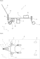
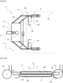
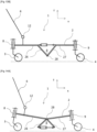
- figure 1 illustrates, schematically and in a non-limiting manner, an electric propulsion system according to one or more embodiments of the invention.
- figure 1 is a top view of the electric propulsion system 1.
- the electric propulsion system 1 comprises a chassis 2.
- the x-axis corresponds to the longitudinal axis of the chassis 2 and to the main direction of movement of the propulsion system 1, and the y-axis corresponds to the lateral axis of the chassis 2.
- the chassis 2 supports three wheels (alternatively the chassis 2 can comprise four wheels).
- the chassis 2 supports a motorized wheel 3 (alternatively the chassis 2 can support two wheels 3), which is a wheel driven by an electric machine (not shown).
- the motorized wheel 3 is steerable relative to the chassis 2, about a vertical axis 8.
- the chassis 2 supports two non-motorized wheels 4, which are two wheels not driven by an electric machine.
- the non-motorized wheels 4 are steerable relative to the chassis around vertical axes 9.
- the electric propulsion system 1 further comprises coupling means 5.
- the electric propulsion system 1 comprises two coupling means 5 on either side of the chassis in the lateral direction (y axis) in order to carry out the coupling by means of two wheels of the rolling object (not shown).
- the coupling means 5 are represented in a simplified manner as a clamp.
- the lateral movement of the coupling means is indicated by a double arrow. This lateral movement can be used to grip and orient the wheels of the rolling object.
- the coupling means 5 are placed, in the x direction, between the motorized wheel 3 and the non-motorized wheels 4.
- the electric propulsion system 1 comprises a handlebar 6, for example in the form of a rod equipped with a handle (not shown) articulated relative to the chassis 2.
- the electric propulsion system 1 comprises a support platform 7 (for example of a user). The platform 7 is located at the end of the chassis 2 which supports the non-motorized wheels 4.
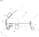
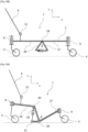
- FIG 2 illustrates, schematically and in a non-limiting manner, an electric propulsion system according to one or more embodiments of the invention.
- figure 2 is a side view of the electric propulsion system1.
- the electric propulsion system 1 comprises a chassis 2.
- the x-axis corresponds to the longitudinal axis of the chassis 2 and to the main direction of movement of the propulsion system, and the z-axis corresponds to the vertical axis of the chassis 2.
- the chassis supports three wheels.
- the chassis 2 supports a motorized wheel 3, which is a wheel driven by an electric machine 10 by means of a drive 17, for example a belt or a chain (alternatively the electric machine 10 can be connected directly to the motorized wheel 3).
- the motorized wheel 3 is orientable relative to the chassis 2, about a vertical axis 8.
- the electric machine 10 can be integral with the pivot 8 of the motorized wheel 3.
- the chassis 2 supports two non-motorized wheels 4, which are two wheels not driven by an electric machine.
- the non-motorized wheels 4 are steerable relative to the chassis around vertical axes 9.
- the electric propulsion system 1 further comprises coupling means 5.
- the electric propulsion system 1 comprises two coupling means 5 on either side of the chassis in the lateral direction (y axis) in order to carry out the coupling by means of two wheels of the rolling object (not shown).
- the coupling means 5 are represented in a simplified manner as a clamp.
- the vertical movement of the coupling means 5 is indicated by a double arrow.
- the coupling means 5 are placed, in the x direction, between the motorized wheel 3 and the non-motorized wheels 4.
- the electric propulsion system 1 comprises a handlebar 6, for example in the form of a rod equipped with a handle (not shown) articulated relative to the chassis 2 by means of a joint 12 with a horizontal axis, in the lateral direction of the chassis 2 (perpendicular to the plane of the figure).
- the electric propulsion system 1 comprises a battery 11. The battery 11 is placed on the chassis 2 near the electric machine 10 and the motorized wheel 3.
- FIG 3 illustrates, schematically and in a non-limiting manner, an electric propulsion system according to one or more embodiments of the invention.
- figure 3 is a side view of the electric propulsion system 1.
- the electric propulsion system 1 comprises a chassis 2.
- the x-axis corresponds to the longitudinal axis of the chassis 2 and to the main direction of movement of the propulsion system, and the z-axis corresponds to the vertical axis of the chassis 2.
- the chassis supports three wheels.
- the chassis 2 supports a motorized wheel 3, which is a wheel driven by an electric machine 10 by means of a drive 17, for example a belt or a chain.
- the motorized wheel 3 is orientable relative to the chassis 2, about a vertical axis 8.
- the electric machine 10 can be secured to the pivot 8 of the motorized wheel 3.
- the chassis 2 supports two non-motorized wheels 4, which are two wheels not driven by an electric machine.
- the non-motorized wheels 4 are steerable relative to the chassis around vertical axes 9.
- the electric propulsion system 1 further comprises coupling means 5.
- the electric propulsion system 1 comprises two coupling means 5 on either side of the chassis in the lateral direction (y axis) in order to carry out the coupling by means of two wheels of the rolling object (not shown).
- the coupling means 5 are represented in a simplified manner as a clamp.
- the vertical movement of the coupling means 5 is indicated by a double arrow. This vertical movement of the coupling means allows in particular the lifting of the wheels of the rolling object.
- the coupling means 5 are placed, in the x direction, between the motorized wheel 3 and the non-motorized wheels 4.
- motorized 4 the propulsion system 1 comprises a handlebar 6, for example in the form of a rod equipped with a grip (not shown) articulated relative to the vertical orientation axis 8 of the motorized wheel 3 by means of a joint 12 with a horizontal axis, parallel to the axis of rotation of the motorized wheel.
- the electric propulsion system 1 comprises a battery 11. The battery 11 is placed on the chassis 2 near the non-motorized wheels 4.
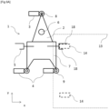
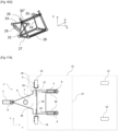
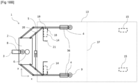
- FIG 4 illustrates, schematically and in a non-limiting manner, an electric propulsion system according to one or more embodiments of the invention coupled to a rolling object 13.
- the figure 1 is a top view of the electric propulsion system 1 and the rolling object 13.
- the embodiment of the figure 4 corresponds to the embodiment of the figure 1 .
- the rolling object 13 may be of any type, in particular a rolling bed.
- the rolling object comprises two wheels 14, arbitrarily called rear wheels, and two wheels 15, arbitrarily called front wheels.
- the electric propulsion system 1 comprises a chassis 2.
- the x axis corresponds to the longitudinal axis of the chassis 2 and to the main direction of movement of the propulsion system, and the y axis corresponds to the lateral axis of the chassis 2.
- the chassis supports three wheels.
- the chassis 2 supports a motorized wheel 3, which is a wheel driven by an electric machine (not shown).
- the motorized wheel 3 is orientable relative to the chassis 2, around a vertical axis 8.
- the chassis 2 supports two non-motorized wheels 4, which are two wheels not driven by an electric machine.
- the non-motorized wheels 4 are steerable relative to the chassis around vertical axes 9.
- the electric propulsion system 1 further comprises coupling means 5.
- the electric propulsion system 1 comprises two coupling means 5 on either side of the chassis in the lateral direction (y-axis) in order to carry out the coupling by means of two rear wheels 14 of the rolling object.
- the coupling means 5 are represented in a simplified manner as a clamp.
- the rear wheels 14 of the rolling object are placed in the clamp, and are oriented along the y-axis, that is to say along an axis perpendicular to the longitudinal axis (x-axis) of the chassis 2.
- the front wheels 15 of the rolling object are free and not coupled.
- the electric propulsion system 1 also comprises a handlebar 6, for example in the form of a rod equipped with a handle (not shown) articulated relative to the chassis 2.
- the electric propulsion system 1 comprises a support platform 7 (for example of a user). The platform 7 is located at the end of the chassis 2 which supports the non-motorized wheels 4.
- the coupling means 5, the non-motorized wheels 4, the platform 7, and a major part of the chassis 2 are located below the rolling object. Only the motorized wheel 3 and the handlebar 6 can protrude from the rolling object 13 in the longitudinal direction x of the chassis 2.
- the double dotted arrows indicate that the coupling means 5 can move longitudinally along an axis parallel to the x axis, so as to approach the driven wheel 3 or on the contrary so as to approach the non-driven wheels 4.
- the coupling means can move independently of one another.
- FIG 5 illustrates, schematically and in a non-limiting manner, an electric propulsion system according to one or more embodiments of the invention, the electric propulsion system 1 being used as a scooter by a user 16.
- the figure 5 is a side view of the propulsion system 1.
- the propulsion system of the figure 5 corresponds roughly to the propulsion system of the figure 3 .
- the electric propulsion system 1 comprises a chassis 2.
- the x-axis corresponds to the longitudinal axis of the chassis 2 and to the main direction of movement of the propulsion system, and the z-axis corresponds to the vertical axis of the chassis 2.
- the chassis supports three wheels.
- the chassis 2 supports a motorized wheel 3, which is a wheel driven by an electric machine 10 by means of a drive 17, for example a belt or a chain.
- the motorized wheel 3 is orientable relative to the chassis 2, around a vertical axis 8.
- the electric machine 10 can be secured to the pivot 8 of the motorized wheel 3.
- the chassis 2 supports two non-motorized wheels 4, which are two wheels not driven by an electric machine.
- the non-motorized wheels 4 are steerable relative to the chassis around vertical axes 9.
- the electric propulsion system 1 further comprises coupling means 5.
- the electric propulsion system 1 comprises two coupling means 5 on either side of the chassis in the lateral direction (y axis) in order to carry out the coupling by means of two wheels of the rolling object (not shown).
- the coupling means 5 are represented in a simplified manner as a clamp.
- the coupling means 5 are placed, in the x direction, between the motorized wheel 3 and the non-motorized wheels 4.
- the electric propulsion system 1 comprises a handlebar 6, for example in the form of a rod equipped with a handle (not shown) articulated relative to the pivot 8 by means of a joint 12 with a horizontal axis, parallel to the axis of rotation of the motorized wheel.
- the electric propulsion system 1 comprises a battery 11.
- the battery 11 is placed on the handlebar 6.
- the chassis 2 comprises in its longitudinal end near the non-motorized wheels 4, a platform 7.
- the electric propulsion system is used as a scooter by the user 16: the user stands on the platform 7 and holds and/or operates the handlebar 6.
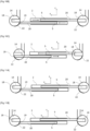
- FIG. 6A illustrates (in top view), schematically and in a non-limiting manner, the gripping sequence of an electric propulsion system 1 according to one or more embodiments of the invention by approaching the coupling means 5 of a rear wheel 14 of the rolling object 13 until the introduction of the wheel of the rolling object between two gripping elements 18, the axis of rotation of the rear wheel 14 being perpendicular to the main axis of the two gripping elements 18.
- the distance between the gripping elements 18 and the ground during the gripping sequence is substantially 0.5 times the diameter of the wheel 14 of the rolling object and the distance between the two gripping elements is 8 cm, i.e., a distance greater than the thickness (6 cm) of the wheel 14 of the rolling object.
- the gripping element 18 arranged on the side of (facing) the motorized wheel 3 is longer than the gripping element 18 arranged on the side of the non-motorized wheels 4.
- the gripping element 18 arranged on the side of the motorized wheel 3, is 6 cm longer than the gripping element 18 arranged on the side of the non-motorized wheels 4.
- the gripping element 18 can be a rod or a plate.
- FIG. 6B And 6C illustrate (in top view), schematically and in a non-limiting manner, the orientation sequence of an electric propulsion system 1 according to one or more embodiments of the invention by rotating the gripped wheel 14 around its point of contact with the ground in order to orient the gripped wheel 14 (by the gripping elements 18) in a direction substantially perpendicular to the longitudinal direction of the chassis of the propulsion system.
- the orientation is carried out by rotating the electric propulsion system 1 around the vertical axis of the gripped wheel 14 until the gripped wheel 14 is placed in a direction parallel to the lateral direction of the chassis 2.
- the rotation by the electric propulsion system 1 of the gripped wheel 14 (itself linked to the rolling object 13 by a vertical axis of rotation not passing through said point of contact), has the consequence of causing a slight displacement of the rolling object 13.
- the displacement of the rolling object 13 then causes a rotation of a second wheel 14 of the rolling object around its point of contact with the ground.
- the rotation of the second wheel 14 of the rolling object is similar to that imposed on the first rear wheel 14 (Caddy TM effect).
- the rotation of the electric propulsion system 1 is applied until the second set of two gripping elements 18 comes into contact with said second wheel 14 of the rolling object.
- the directional movement of the non-motorized wheels 4 of the structure is preferably left free.
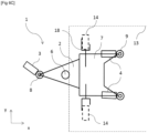
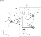
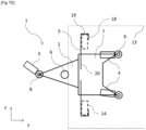
- FIG. 6D illustrates (in top view), schematically and in a non-limiting manner, the immobilization sequence of an electric propulsion system 1 according to one or more embodiments of the invention by moving an immobilization branch 19, arranged between the gripping elements 18, so as to contact and block the gripped wheels 14, for example, by means of one or more jacks, for example an electric jack, a screw system nuts, rack and pinion system or any similar means.
- the immobilizing branches 19 are arranged on the inside of the chassis 2 relative to the gripping elements 18.
- lashing arms 20 are moved apart from each other (i.e., moved towards the outside of the chassis 2, for example by means of jacks), until the immobilizing branches 19 come into contact and then into abutment with the gripped wheels 14.
- the directional movement of the non-motorized wheels 4 of the structure is preferably left free.
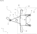
- FIGS 7A , 7B , 7C And 7D illustrate (in top view), schematically and in a non-limiting manner, the sequences of gripping, orientation and immobilization similar to the sequences defined above with reference to the Figures 6A , 6B , 6C And 6D , with the difference that the immobilizing branches 19 are arranged on the outer side of the chassis 2 relative to the gripping elements 18.
- the grip sequence is not completed.
- the user can cause the gripping elements 18 to move around the wheel 14 to complete the gripping sequence, before, during or after the rotation sequence.
- the lashing arms 20 are brought closer together (i.e., moved towards the inside of the chassis 2, for example by means of jacks), until the immobilizing branches 19 come into contact and then into abutment with the gripped wheels 14.
- the directional movement of the non-motorized wheels 4 of the structure is preferably left free.
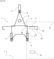
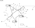
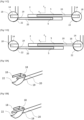
- FIGS. 8A , 8B And 8C illustrate (in top view), schematically and in a non-limiting manner, the sequences of gripping, orientation and immobilization similar to the sequences defined above with reference to the Figures 7A , 7B , 7C And 7D , with the difference that the coupling means 5 comprise a stop element 21 arranged on the inner side of the coupling means 5 relative to the gripping elements 18, the stop element 21 being provided to guide the wheel 14 of the rolling object 13 so that said wheel 14 comes into abutment against the gripping element 18 arranged on the side of the motorized wheel 3.
- Figures 8A And 8B illustrate in particular that the gripping element 18 arranged on the side of the motorized wheel 3 and the stop element 21 make it possible to guide the wheel 14 of the rolling object 13 during the orientation sequence without it being necessary to introduce said wheel 14 between the two gripping elements 18.
- Figure 8C illustrates the gripping and immobilization sequences ending at the same time when the lashing arms 20 are brought closer together (i.e., moved towards the inside of the chassis 2, for example by means of jacks), until the immobilization branches 19 come into contact and then into abutment with the gripped wheels 14.
- the directional movement of the non-motorized wheels 4 of the structure is preferably left free.
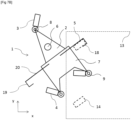
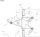
- FIGS. 9A , 9B And 9C illustrate (in top view), schematically and in a non-limiting manner, the sequences of gripping, orientation and immobilization similar to the sequences defined above with reference to the Figures 8A , 8B And 8C , with the difference that the coupling means 5 are supported by the non-motorized wheels 4 and that the immobilizing branches 19 form a clamp system that can be tightened by a jack adapted to bring the lashing arms 20 closer together by a rotational movement.
- the lashing arms 20 are connected to each other and are set in motion by a common actuator, such as a jack.
- each lashing arm is rotatable about a vertical pivot axis, the main axis of a lashing arm forming, relative to the longitudinal axis of the chassis (i.e., the x axis), an angle ⁇ substantially greater than 45° at the end of the rotation sequence ( Figure 9B ), and an angle ⁇ significantly less than 45° at the end of the immobilization sequence ( Figure 9C ).
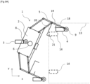
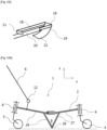
- FIGS. 10A , 10B and 10C illustrate (in side view in the transverse direction), schematically and in a non-limiting manner, the immobilization sequences similar to the sequences defined above with reference to the Figures 6C , 6D And 7D , respectively, in which the immobilizing branches 19 comprise a support element 22 (flat, inclined or curved or square-shaped piece adapted to pass under the gripped wheel 14 and support the immobilized wheel 14).
- the support element 22 is adapted to pass under the wheel 14 seized during the actuation of the lashing arms 20 and thus support the immobilized wheel 14.
- Figures 11A and 11B illustrate (in side view in the transverse direction), schematically and in a non-limiting manner, immobilization sequences, in which the immobilized wheels 14 are oriented in the same direction along the axis perpendicular to the longitudinal direction of the chassis (immobilization elements arranged in opposition).
- Figure 11C illustrates, schematically and in a non-limiting manner, an immobilization sequence, in which the immobilized wheels 14 are oriented in different directions and arranged in opposition along the axis perpendicular to the longitudinal direction of the chassis.
- figure 11D illustrates, schematically and in a non-limiting manner, an immobilization sequence, in which the immobilized wheels 14 are oriented in different directions and arranged facing each other along the axis perpendicular to the longitudinal direction of the chassis.
- the Figures 11A, 11B , 11C and 11D are illustrated with immobilizing branches 19 arranged on the inner side of the chassis 2 relative to the gripping elements 18, it is also envisaged to immobilize the wheels 14 of the object rolling in the same direction, in opposition or facing each other with immobilizing branches 19 arranged on the outer side of the chassis 2 relative to the gripping elements 18.
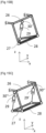
- FIGS 12A-12I illustrate (in three-dimensional view), schematically and in a non-limiting manner, gripping and immobilization means according to one or more embodiments.
- the Figure 12A shows a lashing arm 20, comprising an immobilizing branch 19 provided with a spoon- or shovel-shaped support element 22, the lashing arm 20 being extended by two gripping elements 18 of substantially identical length.
- Figure 12B shows an example in which one gripping element 18 is substantially longer than the other gripping element.
- the gripping element 18 arranged on the side of (closest to) the motorized wheel 3, is substantially longer than the gripping element 18 arranged on the side of the non-motorized wheel(s) 4, thereby facilitating the gripping sequence by serving as a guide when gripping the wheel 14 of the rolling object 13.
- Figures 12C-12G show examples in which a movable part 23, such as a rod or a plate (eg metal), is connected to at least one gripping element 18 through an axis of rotation 24, the movable part 23 being arranged on the end of the gripping element 18 opposite the immobilization branch 19.
- the movable part 23 makes it possible to limit the size of the gripping element 18 during the gripping sequence, and facilitates the maintenance of the wheel 14 gripped between the gripping elements 18 during the rotation sequence.
- the movable part 23 comprises a substantially vertical main axis and the rotation axis 24 is parallel to the longitudinal direction of the chassis.
- the movable part 23 is preferably arranged downwards relative to the gripping element 18 in order to increase the compactness of the coupling means.
- the movable part 23 comprises a substantially horizontal main axis, is parallel to the longitudinal direction of the chassis, is arranged on the side opposite the adjacent gripping element 18, and comprises a vertical axis of rotation 24.
- the moving part 23 as described in the Figure 12E further comprises an internal portion 25 arranged on the side opposite the adjacent gripping element 18.
- the length of the internal portion is strictly less than the distance between the two gripping elements 18 to allow the introduction of the gripped wheel 14 between the gripping elements 18.
- the internal portion 25 makes it possible in particular to serve as a support point for the actuation of the moving part around the axis of rotation when the wheel 14 of the rolling object comes into abutment against said internal portion 25.
- figure 12H shows an example of a lashing arm 20 of external gripping coupling means, in which a stop element 21 is arranged on the lashing arm 20.
- the figure 12I shows an example of a 20-way lashing arm external gripping coupling, in which the stop element 21 is arranged on the gripping element 18.
- FIGS 13A , 13B , 14A And 14B illustrate (in side view in a lateral direction), schematically and in a non-limiting manner, lifting means in the low position ( Figures 13A And 14A ) and in high position ( Figure 13B And 14B ) according to one or more embodiments, comprising an articulated structure in the central part of the chassis (eg between the at least one motorized wheel and the at least one non-motorized wheel).
- the articulated structure comprises on the one hand, a first chassis portion called “drive portion 26" supported by the at least one motorized wheel 3, and comprises on the other hand, a second chassis portion called "non-motorized portion 27" supported by the at least one non-motorized wheel 4.
- the chassis portions 26 and 27 are articulated relative to each other about a horizontal axis of rotation called "articulation axis 28" substantially perpendicular to the longitudinal direction of the chassis.
- the electric propulsion system 1 performs the lifting sequence by actuating a first actuator so as to cause a substantially vertical upward movement of the articulation axis 28 by modifying the angle ⁇ between the chassis portions 26 and 27 at the articulation axis 28.
- the hinge pin 28 is arranged on a lower end of the frame portions 26 and 27, and the angle ⁇ is increased to move from the low position to the high position.
- the hinge pin 28 is arranged on an upper end of the frame portions 26 and 27, and the angle ⁇ is decreased to move from the low position to the high position.
- FIGS 15A to 15F illustrate (the Figures 15A And 15D in side view in a lateral direction, and the figures 15B, 15C , 15E And 15F in three-dimensional view), schematically and in a non-limiting manner, lifting means in the low position ( Figures 15A , 15B and 15C ) and in high position ( figure 15D, 15E And 15F ) according to one or more embodiments, in which the articulation axis 28 is arranged on a lower end of the chassis portions 26 and 27, and the angle ⁇ is increased to move from the low position to the high position.
- the first actuator 29 is connected along the longitudinal axis of the chassis 2 (i.e., according to the xz view of the figures) on the one hand, to a central portion 30 of the driving portion 26, and on the other hand, to a rear end portion 31 of the non-motorized portion 27 (i.e., end facing the driving portion 26).
- the first actuator 29 may be unique and arranged adjacent to a central portion 30' according to a top view (along a substantially horizontal axis and substantially perpendicular to the longitudinal direction of the chassis 2) of the chassis portions 26 and 27.
- only one lifting actuator is necessary.
- the first actuator 29 is assisted by an actuator complementary 29', each actuator being arranged adjacent to the lateral end portions 30" according to a top view (i.e., according to the xy view of the figures) of the drive portion 26.
- the lifting actuators are arranged on the sides of the chassis in order to free up space in the middle of the chassis and to gain in compactness of the coupling means.
- FIGS 16A to 16D illustrate (the Figures 16A And 16C in side view in a lateral direction, and the Figures 16B , And 16D in three-dimensional view), schematically and in a non-limiting manner, lifting means in the low position ( Figures 16A And 16B ) and in high position ( figure 16C And 16D ) according to one or more embodiments, in which the articulation axis 28 is arranged on a lower end of the chassis portions 26 and 27, and the angle ⁇ is increased to move from the low position to the high position.
- the first actuator 29 is connected along the longitudinal axis of the chassis 2 (i.e., according to the xz view of the figures) on the one hand, to a central portion 30 of the driving portion 26, and on the other hand, to a rear end portion 31 of the non-motorized portion 27 (i.e., end facing the driving portion 26).
- the first actuator 29 is unique and is arranged adjacent to an end portion 30" according to a top view (i.e., according to the xy view of the figures) of the chassis portions 26 and 27.
- only one lifting actuator is necessary and said actuator is arranged on the sides of the chassis in order to free up space in the middle of the chassis and to gain in compactness of the coupling means.
- the first actuator 29 is adapted to: actuate on the one hand, a crossed connecting rod 32 connected to a first end of the first actuator 29, for example by means of a return 33; and actuate on the other hand, a non-crossed connecting rod 34 connected to the second end of the first actuator 29, for example by means of a shaft 35 passing through the central portion 30 (i.e., horizontal shaft and perpendicular to the longitudinal direction of the chassis).
- One of said connecting rods 32, 34 is connected along the longitudinal axis of the chassis 2 at one of its ends to a central portion (30) of the first chassis portion 26 via the return 33, and at its other end to a rear end portion 31 of the second chassis portion 27.
- the other of said connecting rods 32, 34 is connected along the longitudinal axis of the chassis 2 at one of its ends to a central portion (30) of the driving portion 26 via the element 35, and at its other end to a rear end portion 31 of the non-motorized portion 27.
- the crossed connecting rod 32 is on the same side as the actuator 29 and the non-crossed connecting rod 34 is connected to the actuator 29 by means of the shaft 35.
- the non-crossed connecting rod 34 is on the same side as the actuator 29 and that the crossed connecting rod 32 is connected to the actuator 29 by means of the shaft 35. by means of shaft 35.
- the angle ⁇ is modified from 20° to 90°, preferably from 60° to 90°, between a low position and a high position of the chassis portions 26 and 27.
- FIGS. 17A And 17B illustrate, schematically and in a non-limiting manner, driving assistance means according to one or more embodiments adapted to assist the user in maneuvering the hitch and comprising two extendable arms 36 for modifying the distance between the at least one non-motorized wheel 4 and the securing arms 20.
- Each extendable arm 36 is, on the one hand, supported by the non-motorized wheel 4 through the vertical axis 9, and on the other hand, connected to the non-motorized portion 27.
- the extendable arms 36 make it possible to position the non-motorized wheels 4 as close as possible to the central part 37 of the rolling object (in the longitudinal direction of the chassis).
- the extendable arms 36 are in a retracted position.
- the second actuator is actuated so as to lengthen the extendable arms 36 and increase the distance between the non-motorized wheels 4 of the lashing arms 20.
- the coupling means are shown fixed in a longitudinal position on the chassis. However, they could alternatively comprise an adjustment means in a longitudinal position on the chassis or on the platform.
- the adjustment means may be independent for each of the coupling means, or else allow the simultaneous adjustment of the different coupling means.
- This adjustment means may in particular be controlled by a control means, the user being able to act on this control means, for example by a remote control or a smartphone, to control the movement of one or more coupling means, in the longitudinal direction, towards the front or towards the rear of the electric propulsion system.
- These adjustment means may in particular be used when the wheels of the rolling object are not located in the same plane orthogonal to the longitudinal axis of the rolling object (or of the chassis). They may also be useful for facilitating the gripping of the wheels of the rolling object and helping to ensure the compactness of the coupled or uncoupled system.
- FIGS. 18A And 18B illustrate, schematically and in a non-limiting manner, driving assistance means according to one or more embodiments similar to the driving assistance means with reference to Figures 17A And 17B , except that the wheels 14 of the rolling object 13 are immobilized by external gripping and immobilization.
- the Figure 18A shows the extendable arms 36 in the retracted position and the figure 18B shows the extendable arms 36 in the extended position.
- the directional movement of the non-motorized wheels 4 of the structure is preferentially left free during actuation of the actuator.
- substantially perpendicular corresponds by default to an angle of 78° to 108°
- substantially parallel corresponds by default to an angle of -18° to 18°
- substantially vertical corresponds by default to vertical +/- 18°
- substantially horizontal corresponds by default to horizontal +/-18°.
Landscapes
- Engineering & Computer Science (AREA)
- Chemical & Material Sciences (AREA)
- Combustion & Propulsion (AREA)
- Transportation (AREA)
- Mechanical Engineering (AREA)
- Health & Medical Sciences (AREA)
- Nursing (AREA)
- Life Sciences & Earth Sciences (AREA)
- Animal Behavior & Ethology (AREA)
- General Health & Medical Sciences (AREA)
- Public Health (AREA)
- Veterinary Medicine (AREA)
- Handcart (AREA)
- Invalid Beds And Related Equipment (AREA)
- Arrangement Or Mounting Of Propulsion Units For Vehicles (AREA)
Claims (15)
- Lösbares elektrisches Antriebssystem für ein rollendes Objekt (13), wobei das Antriebssystem (1) ein Fahrgestell (2), das mit mindestens einem von einer elektrischen Maschine (10) angetriebenen Rad (3) und mindestens einem nicht angetriebenen Rad (4) ausgestattet ist, einen Lenker (6) und Mittel zum Ankuppeln (5) des Antriebssystems (1) an das rollende Objekt (13) umfasst, wobei die Ankupplungsmittel (5) Mittel zum Greifen, Ausrichten, Feststellen und Heben mindestens eines Rades (14) des rollenden Objekts (13) umfassen, wobei das Antriebssystem (1) außerdem umfasst:Mittel zur Unterstützung des Fahrens, die mindestens einen Arm variabler Länge (36) umfassen, der dazu eingerichtet ist, eine Änderung des Abstands zwischen dem mindestens einen angetriebenen Rad (3) und dem mindestens einen nicht angetriebenen Rad (4) zu bewirken, dadurch gekennzeichnet, dassdie Mittel zum Ausrichten dazu eingerichtet sind, das mindestens eine Rad (14) des rollenden Objekts (13) in einer Richtung auszurichten, die im Wesentlichen senkrecht zur Längsrichtung (x) des Fahrgestells (2) des Antriebssystems (1) ist.
- Lösbares elektrisches Antriebssystem nach Anspruch 1, wobei der Arm variabler Länge (36) einerseits von dem nicht angetriebenen Rad (4) gestützt wird und andererseits mit dem Fahrgestell (2) verbunden ist oder mit den Ankupplungsmitteln (5) verbunden ist, die ein Feststellelement (19) tragen.
- Lösbares elektrisches Antriebssystem nach Anspruch 1 oder Anspruch 2, wobei der Arm variabler Länge (36) im Wesentlichen horizontal ist und eine Hauptachse umfasst, die im Wesentlichen parallel zur Längsrichtung (x) des Fahrgestells (2) ist.
- Lösbares elektrisches Antriebssystem nach Anspruch 3, welches einen Aktuator umfasst, der mit dem Arm variabler Länge (36) und mit dem nicht motorgetriebenen Abschnitt (27) verbunden ist, um eine Änderung der Länge des Armes variabler Länge (36) zu bewirken.
- Lösbares elektrisches Antriebssystem nach Anspruch 4, welches Mittel zur Richtungsblockierung umfasst, die dazu eingerichtet sind, die Drehung des nicht motorgetriebenen Rades (4) um eine vertikale Achse zu blockieren/zu entsperren, und wobei die Lenkbewegung des nicht motorgetriebenen Rades (4) so eingerichtet ist, dass sie während der Betätigung des Aktuators frei erfolgen kann.
- Lösbares elektrisches Antriebssystem nach einem der vorhergehenden Ansprüche, wobei die Mittel zum Greifen mindestens einen Satz von zwei Greifelementen (18) umfassen, deren Hauptachsen im Wesentlichen senkrecht zur Längsrichtung (x) des Fahrgestells (2) sind, wobei die zwei Greifelemente (18) dazu eingerichtet sind, das Rad (14) des rollenden Objekts (13) zu erfassen.
- Lösbares elektrisches Antriebssystem nach einem der vorhergehenden Ansprüche, wobei die Mittel zum Feststellen einen im Wesentlichen horizontalen Kopplungsarm (20) umfassen, der an einem seiner Enden ein Feststellelement (19) trägt.
- Lösbares elektrisches Antriebssystem nach Anspruch 7, wobei der Arm variabler Länge (36) dazu eingerichtet ist, eine Änderung des Abstands zwischen dem mindestens einen nicht angetriebenen Rad (4) und dem Kopplungsarm (20) zu bewirken.
- Lösbares elektrisches Antriebssystem nach Anspruch 8, wobei der Arm variabler Länge (36) dazu eingerichtet ist, dass der Abstand zwischen dem mindestens einen nicht angetriebenen Rad (4) und dem Kopplungsarm (20) um mindestens 150 mm geändert werden kann.
- Lösbares elektrisches Antriebssystem nach Anspruch 8 oder Anspruch 9, wobei der Arm variabler Länge (36) dazu eingerichtet ist, dass der Abstand zwischen dem mindestens einen nicht angetriebenen Rad (4) und dem Kopplungsarm (20) zwischen 200 und 500 mm geändert werden kann.
- Lösbares elektrisches Antriebssystem nach einem der vorhergehenden Ansprüche, wobei die Mittel zum Heben eine Gelenkstruktur im mittleren Teil des Fahrgestells zwischen dem mindestens einen motorgetriebenen Rad (3) und dem mindestens einen nicht motorgetriebenen Rad (4) umfassen.
- Lösbares elektrisches Antriebssystem nach einem der vorhergehenden Ansprüche, wobei die Ankupplungsmittel Mittel zur Einstellung der Längsposition umfassen, wobei die Mittel zur Einstellung vorzugsweise von einem Steuerungsmittel gesteuert werden.
- Gespann, welches ein rollendes Objekt (13) und ein elektrisches Antriebssystem (1) nach einem der vorhergehenden Ansprüche umfasst, wobei das rollende Objekt (13) durch die Ankupplungsmittel (5) an das elektrische Antriebssystem (1) angekuppelt ist.
- Gespann nach Anspruch 13, welches Mittel zur Richtungsblockierung umfasst, die dazu eingerichtet sind: die Drehung des nicht motorgetriebenen Rades (4) um eine vertikale Achse zu entsperren, um den Arm variabler Länge (36) zu betätigen; und/oder die Drehung des nicht motorgetriebenen Rades (4) um die vertikale Achse zu blockieren, um das Gespann zu bewegen.
- Verfahren zur Ankupplung eines rollenden Objekts (13) an ein elektrisches Antriebssystem (1) nach einem der Ansprüche 1 bis 12, welches mindestens den folgenden Schritt umfasst:
Bewirken einer Änderung des Abstands zwischen dem mindestens einen angetriebenen Rad (3) und dem mindestens einen nicht angetriebenen Rad (4) mittels mindestens eines Armes variabler Länge (36).
Applications Claiming Priority (2)
| Application Number | Priority Date | Filing Date | Title |
|---|---|---|---|
| FR1902772A FR3093916B1 (fr) | 2019-03-18 | 2019-03-18 | Dispositif d’aide à la conduite de roue de système de propulsion électrique amovible pour un objet roulant |
| PCT/EP2020/054140 WO2020187517A1 (fr) | 2019-03-18 | 2020-02-18 | Dispositif d'aide a la conduite de roue de systeme de propulsion electrique amovible pour un objet roulant |
Publications (3)
| Publication Number | Publication Date |
|---|---|
| EP3937873A1 EP3937873A1 (de) | 2022-01-19 |
| EP3937873C0 EP3937873C0 (de) | 2024-10-16 |
| EP3937873B1 true EP3937873B1 (de) | 2024-10-16 |
Family
ID=67514811
Family Applications (1)
| Application Number | Title | Priority Date | Filing Date |
|---|---|---|---|
| EP20705203.6A Active EP3937873B1 (de) | 2019-03-18 | 2020-02-18 | Vorrichtung zur unterstützung des antriebs eines rades eines abnehmbaren elektrischen antriebssystems für ein rollendes objekt |
Country Status (9)
| Country | Link |
|---|---|
| US (1) | US20220161835A1 (de) |
| EP (1) | EP3937873B1 (de) |
| JP (1) | JP2022525457A (de) |
| CN (1) | CN113597294B (de) |
| AU (1) | AU2020242189A1 (de) |
| CA (1) | CA3128231A1 (de) |
| ES (1) | ES2997113T3 (de) |
| FR (1) | FR3093916B1 (de) |
| WO (1) | WO2020187517A1 (de) |
Families Citing this family (2)
| Publication number | Priority date | Publication date | Assignee | Title |
|---|---|---|---|---|
| CN113928390B (zh) * | 2021-11-09 | 2023-09-05 | 江苏徐苏新能源科技有限公司 | 一种节能型的钢筋桁架生产线 |
| US11891101B1 (en) * | 2022-11-22 | 2024-02-06 | Ryan Dixson | Motorized utility cart assembly |
Family Cites Families (12)
| Publication number | Priority date | Publication date | Assignee | Title |
|---|---|---|---|---|
| BE1007895A3 (nl) * | 1993-12-21 | 1995-11-14 | Elaut N V | Inrichting voor het verplaatsen van bedden. |
| EP1284709A2 (de) | 2000-05-11 | 2003-02-26 | Hill-Rom Services, Inc. | Motorantriebssystem für ein bett |
| US7533742B2 (en) * | 2001-10-26 | 2009-05-19 | Dane Industries, Inc. | Bed transfer system |
| US7594284B2 (en) * | 2004-05-25 | 2009-09-29 | Nu Star Inc. | Transport aid for wheeled support apparatus |
| EP2039336A3 (de) * | 2007-09-06 | 2009-06-03 | Holdingselskabet MKR Finans ApS | Transportsystem mit Antriebseinheit |
| US8165718B2 (en) * | 2010-07-30 | 2012-04-24 | Toyota Motor Engineering & Manufacturing North America, Inc. | Robotic transportation devices and systems |
| US9913771B2 (en) * | 2011-06-17 | 2018-03-13 | Austech & Design Pty Ltd | Lifting and transporting device for wheeled objects including hospital beds |
| DK177585B1 (en) | 2012-04-18 | 2013-11-04 | Mim Holding As | Transport Cart configured to Transport Beds with Wheels |
| DE102015011200B4 (de) * | 2015-08-25 | 2019-01-03 | MAQUET GmbH | Patienten-/Lagerflächentransporter mit einem Bediengriff |
| NL2017890B1 (nl) * | 2016-11-29 | 2018-06-11 | Josh Ip Iii B V | Medische transportinrichting, hulpaandrijving, en werkwijze voor het transporteren van een dergelijke transportinrichting |
| EP3534860B1 (de) * | 2017-01-13 | 2022-12-07 | Siemens Healthcare GmbH | Transportvorrichtung und verfahren für den betrieb einer derartigen transportvorrichtung |
| FR3089786B1 (fr) * | 2018-12-18 | 2020-12-04 | Ifp Energies Now | Système de propulsion électrique amovible pour un objet roulant, notamment un lit |
-
2019
- 2019-03-18 FR FR1902772A patent/FR3093916B1/fr active Active
-
2020
- 2020-02-18 CA CA3128231A patent/CA3128231A1/fr active Pending
- 2020-02-18 ES ES20705203T patent/ES2997113T3/es active Active
- 2020-02-18 WO PCT/EP2020/054140 patent/WO2020187517A1/fr not_active Ceased
- 2020-02-18 EP EP20705203.6A patent/EP3937873B1/de active Active
- 2020-02-18 JP JP2021555546A patent/JP2022525457A/ja not_active Ceased
- 2020-02-18 CN CN202080021776.5A patent/CN113597294B/zh active Active
- 2020-02-18 US US17/432,623 patent/US20220161835A1/en not_active Abandoned
- 2020-02-18 AU AU2020242189A patent/AU2020242189A1/en not_active Abandoned
Also Published As
| Publication number | Publication date |
|---|---|
| JP2022525457A (ja) | 2022-05-16 |
| EP3937873A1 (de) | 2022-01-19 |
| ES2997113T3 (en) | 2025-02-14 |
| EP3937873C0 (de) | 2024-10-16 |
| CA3128231A1 (fr) | 2020-09-24 |
| FR3093916A1 (fr) | 2020-09-25 |
| CN113597294A (zh) | 2021-11-02 |
| AU2020242189A1 (en) | 2021-09-23 |
| WO2020187517A1 (fr) | 2020-09-24 |
| CN113597294B (zh) | 2023-01-13 |
| FR3093916B1 (fr) | 2021-05-07 |
| US20220161835A1 (en) | 2022-05-26 |
Similar Documents
| Publication | Publication Date | Title |
|---|---|---|
| EP0755841B1 (de) | Lastförderwagen | |
| EP3937873B1 (de) | Vorrichtung zur unterstützung des antriebs eines rades eines abnehmbaren elektrischen antriebssystems für ein rollendes objekt | |
| EP3949925B1 (de) | Abnehmbares elektrisches antriebssystem für ein rollendes objekt, gleichzeitiges und kombiniertes greifen und entfernen der räder in längsrichtung | |
| EP3897503B1 (de) | Abnehmbares elektrisches antriebssystem für ein rollendes objekt, insbesondere ein bett | |
| EP4157188B1 (de) | Abnehmbares elektronisches antriebssystem für ein rollendes objekt mit automatischer richtungsblockierung | |
| WO2021190952A1 (fr) | Systeme de propulsion electrique amovible pour un objet roulant avec un dispositif d'effacement du guidon | |
| WO2020187516A1 (fr) | Dispositif de levage de roue de systeme de propulsion electrique amovible pour un objet roulant | |
| WO2020187499A1 (fr) | Dispositif de prehension de roue de systeme de propulsion electrique amovible pour un objet roulant | |
| EP2836413B1 (de) | Schwenkbarer wagen oder werkzeugsträger wobei der fahrer am boden steht | |
| EP1927525B1 (de) | Zuführschlitten für Werkstücke zu Produktionslinien | |
| WO2020187515A1 (fr) | Dispositif d'immobilisation de roue de systeme de propulsion electrique amovible pour un objet roulant | |
| EP4157187B1 (de) | Abnehmbares elektrisches antriebssystem für ein rollobjekt mit mitteln zum kombinierten und gleichzeitigen greifen und heben | |
| FR2490166A1 (fr) | Vehicule equipe de dispositifs de transbordement lateral de conteneurs | |
| EP4125763A1 (de) | Abnehmbares elektrisches antriebssystem für ein rollendes objekt mit einer vorrichtung zur entriegelung des lenkers | |
| WO2013139689A1 (fr) | Systeme de traction pour un vehicule et procede pour assurer une traction securisee d'un vehicule sur un sol | |
| FR3121417A1 (fr) | Diable motorisé à double basculement | |
| FR2983813A1 (fr) | Diable gerbeur motorise | |
| FR3161183A1 (fr) | Diable a assistance | |
| WO2012085640A1 (fr) | Ensemble de transporte constitué d'un tracteur motorisé et d'un mobile monté sur roues | |
| WO1999039925A1 (fr) | Appareil demontable pour demonter et remonter une roue de vehicule |
Legal Events
| Date | Code | Title | Description |
|---|---|---|---|
| STAA | Information on the status of an ep patent application or granted ep patent |
Free format text: STATUS: UNKNOWN |
|
| STAA | Information on the status of an ep patent application or granted ep patent |
Free format text: STATUS: THE INTERNATIONAL PUBLICATION HAS BEEN MADE |
|
| PUAI | Public reference made under article 153(3) epc to a published international application that has entered the european phase |
Free format text: ORIGINAL CODE: 0009012 |
|
| STAA | Information on the status of an ep patent application or granted ep patent |
Free format text: STATUS: REQUEST FOR EXAMINATION WAS MADE |
|
| 17P | Request for examination filed |
Effective date: 20211210 |
|
| AK | Designated contracting states |
Kind code of ref document: A1 Designated state(s): AL AT BE BG CH CY CZ DE DK EE ES FI FR GB GR HR HU IE IS IT LI LT LU LV MC MK MT NL NO PL PT RO RS SE SI SK SM TR |
|
| DAV | Request for validation of the european patent (deleted) | ||
| DAX | Request for extension of the european patent (deleted) | ||
| GRAP | Despatch of communication of intention to grant a patent |
Free format text: ORIGINAL CODE: EPIDOSNIGR1 |
|
| STAA | Information on the status of an ep patent application or granted ep patent |
Free format text: STATUS: GRANT OF PATENT IS INTENDED |
|
| INTG | Intention to grant announced |
Effective date: 20231117 |
|
| GRAJ | Information related to disapproval of communication of intention to grant by the applicant or resumption of examination proceedings by the epo deleted |
Free format text: ORIGINAL CODE: EPIDOSDIGR1 |
|
| STAA | Information on the status of an ep patent application or granted ep patent |
Free format text: STATUS: REQUEST FOR EXAMINATION WAS MADE |
|
| INTC | Intention to grant announced (deleted) | ||
| GRAP | Despatch of communication of intention to grant a patent |
Free format text: ORIGINAL CODE: EPIDOSNIGR1 |
|
| STAA | Information on the status of an ep patent application or granted ep patent |
Free format text: STATUS: GRANT OF PATENT IS INTENDED |
|
| INTG | Intention to grant announced |
Effective date: 20240514 |
|
| RIN1 | Information on inventor provided before grant (corrected) |
Inventor name: SANZ, ELENA Inventor name: VENTURI, STEPHANE |
|
| GRAS | Grant fee paid |
Free format text: ORIGINAL CODE: EPIDOSNIGR3 |
|
| GRAA | (expected) grant |
Free format text: ORIGINAL CODE: 0009210 |
|
| STAA | Information on the status of an ep patent application or granted ep patent |
Free format text: STATUS: THE PATENT HAS BEEN GRANTED |
|
| AK | Designated contracting states |
Kind code of ref document: B1 Designated state(s): AL AT BE BG CH CY CZ DE DK EE ES FI FR GB GR HR HU IE IS IT LI LT LU LV MC MK MT NL NO PL PT RO RS SE SI SK SM TR |
|
| REG | Reference to a national code |
Ref country code: GB Ref legal event code: FG4D Free format text: NOT ENGLISH |
|
| REG | Reference to a national code |
Ref country code: CH Ref legal event code: EP |
|
| REG | Reference to a national code |
Ref country code: IE Ref legal event code: FG4D Free format text: LANGUAGE OF EP DOCUMENT: FRENCH |
|
| REG | Reference to a national code |
Ref country code: DE Ref legal event code: R096 Ref document number: 602020039508 Country of ref document: DE |
|
| U01 | Request for unitary effect filed |
Effective date: 20241115 |
|
| U07 | Unitary effect registered |
Designated state(s): AT BE BG DE DK EE FI FR IT LT LU LV MT NL PT RO SE SI Effective date: 20241121 |
|
| REG | Reference to a national code |
Ref country code: ES Ref legal event code: FG2A Ref document number: 2997113 Country of ref document: ES Kind code of ref document: T3 Effective date: 20250214 |
|
| PG25 | Lapsed in a contracting state [announced via postgrant information from national office to epo] |
Ref country code: HR Free format text: LAPSE BECAUSE OF FAILURE TO SUBMIT A TRANSLATION OF THE DESCRIPTION OR TO PAY THE FEE WITHIN THE PRESCRIBED TIME-LIMIT Effective date: 20241016 Ref country code: IS Free format text: LAPSE BECAUSE OF FAILURE TO SUBMIT A TRANSLATION OF THE DESCRIPTION OR TO PAY THE FEE WITHIN THE PRESCRIBED TIME-LIMIT Effective date: 20250216 |
|
| PG25 | Lapsed in a contracting state [announced via postgrant information from national office to epo] |
Ref country code: GR Free format text: LAPSE BECAUSE OF FAILURE TO SUBMIT A TRANSLATION OF THE DESCRIPTION OR TO PAY THE FEE WITHIN THE PRESCRIBED TIME-LIMIT Effective date: 20250117 |
|
| PGFP | Annual fee paid to national office [announced via postgrant information from national office to epo] |
Ref country code: CH Payment date: 20250301 Year of fee payment: 6 |
|
| PG25 | Lapsed in a contracting state [announced via postgrant information from national office to epo] |
Ref country code: PL Free format text: LAPSE BECAUSE OF FAILURE TO SUBMIT A TRANSLATION OF THE DESCRIPTION OR TO PAY THE FEE WITHIN THE PRESCRIBED TIME-LIMIT Effective date: 20241016 |
|
| PG25 | Lapsed in a contracting state [announced via postgrant information from national office to epo] |
Ref country code: RS Free format text: LAPSE BECAUSE OF FAILURE TO SUBMIT A TRANSLATION OF THE DESCRIPTION OR TO PAY THE FEE WITHIN THE PRESCRIBED TIME-LIMIT Effective date: 20250116 |
|
| U21 | Renewal fee for the european patent with unitary effect paid with additional fee |
Year of fee payment: 6 Effective date: 20250520 |
|
| PG25 | Lapsed in a contracting state [announced via postgrant information from national office to epo] |
Ref country code: SM Free format text: LAPSE BECAUSE OF FAILURE TO SUBMIT A TRANSLATION OF THE DESCRIPTION OR TO PAY THE FEE WITHIN THE PRESCRIBED TIME-LIMIT Effective date: 20241016 |
|
| PG25 | Lapsed in a contracting state [announced via postgrant information from national office to epo] |
Ref country code: SK Free format text: LAPSE BECAUSE OF FAILURE TO SUBMIT A TRANSLATION OF THE DESCRIPTION OR TO PAY THE FEE WITHIN THE PRESCRIBED TIME-LIMIT Effective date: 20241016 |
|
| PG25 | Lapsed in a contracting state [announced via postgrant information from national office to epo] |
Ref country code: CZ Free format text: LAPSE BECAUSE OF FAILURE TO SUBMIT A TRANSLATION OF THE DESCRIPTION OR TO PAY THE FEE WITHIN THE PRESCRIBED TIME-LIMIT Effective date: 20241016 |
|
| PLBE | No opposition filed within time limit |
Free format text: ORIGINAL CODE: 0009261 |
|
| STAA | Information on the status of an ep patent application or granted ep patent |
Free format text: STATUS: NO OPPOSITION FILED WITHIN TIME LIMIT |
|
| PG25 | Lapsed in a contracting state [announced via postgrant information from national office to epo] |
Ref country code: MC Free format text: LAPSE BECAUSE OF FAILURE TO SUBMIT A TRANSLATION OF THE DESCRIPTION OR TO PAY THE FEE WITHIN THE PRESCRIBED TIME-LIMIT Effective date: 20241016 |
|
| 26N | No opposition filed |
Effective date: 20250717 |
|
| PG25 | Lapsed in a contracting state [announced via postgrant information from national office to epo] |
Ref country code: IE Free format text: LAPSE BECAUSE OF NON-PAYMENT OF DUE FEES Effective date: 20250218 |
|
| U1N | Appointed representative for the unitary patent procedure changed after the registration of the unitary effect |
Representative=s name: KILBURN & STRODE LLP; GB |
|
| REG | Reference to a national code |
Ref country code: CH Ref legal event code: U11 Free format text: ST27 STATUS EVENT CODE: U-0-0-U10-U11 (AS PROVIDED BY THE NATIONAL OFFICE) Effective date: 20260301 |
|
| REG | Reference to a national code |
Ref country code: ES Ref legal event code: FD2A Effective date: 20260327 |
|
| U20 | Renewal fee for the european patent with unitary effect paid |
Year of fee payment: 7 Effective date: 20260302 |
|
| PGFP | Annual fee paid to national office [announced via postgrant information from national office to epo] |
Ref country code: GB Payment date: 20260223 Year of fee payment: 7 |
|
| PG25 | Lapsed in a contracting state [announced via postgrant information from national office to epo] |
Ref country code: ES Free format text: LAPSE BECAUSE OF NON-PAYMENT OF DUE FEES Effective date: 20250219 |
|
| PGFP | Annual fee paid to national office [announced via postgrant information from national office to epo] |
Ref country code: NO Payment date: 20260218 Year of fee payment: 7 |