EP3937290B1 - Système de gestion de batterie et procédé pour communiquer utilisant un noeud intermédiaire - Google Patents
Système de gestion de batterie et procédé pour communiquer utilisant un noeud intermédiaire Download PDFInfo
- Publication number
- EP3937290B1 EP3937290B1 EP20863211.7A EP20863211A EP3937290B1 EP 3937290 B1 EP3937290 B1 EP 3937290B1 EP 20863211 A EP20863211 A EP 20863211A EP 3937290 B1 EP3937290 B1 EP 3937290B1
- Authority
- EP
- European Patent Office
- Prior art keywords
- level controller
- command signal
- level
- preset
- strength
- Prior art date
- Legal status (The legal status is an assumption and is not a legal conclusion. Google has not performed a legal analysis and makes no representation as to the accuracy of the status listed.)
- Active
Links
- 238000000034 method Methods 0.000 title description 9
- 238000007726 management method Methods 0.000 claims description 58
- 230000004044 response Effects 0.000 claims description 40
- 238000005259 measurement Methods 0.000 claims description 7
- 238000004891 communication Methods 0.000 description 52
- 238000010586 diagram Methods 0.000 description 16
- 239000000470 constituent Substances 0.000 description 13
- 230000005540 biological transmission Effects 0.000 description 7
- 230000014509 gene expression Effects 0.000 description 3
- 238000012544 monitoring process Methods 0.000 description 3
- 238000007796 conventional method Methods 0.000 description 2
- 238000005516 engineering process Methods 0.000 description 2
- 230000008054 signal transmission Effects 0.000 description 2
- 230000005856 abnormality Effects 0.000 description 1
- 238000004590 computer program Methods 0.000 description 1
- 230000000694 effects Effects 0.000 description 1
- 230000006870 function Effects 0.000 description 1
- 238000012986 modification Methods 0.000 description 1
- 230000004048 modification Effects 0.000 description 1
- 230000002093 peripheral effect Effects 0.000 description 1
- 238000012545 processing Methods 0.000 description 1
- 239000004065 semiconductor Substances 0.000 description 1
Images


Classifications
-
- H—ELECTRICITY
- H01—ELECTRIC ELEMENTS
- H01M—PROCESSES OR MEANS, e.g. BATTERIES, FOR THE DIRECT CONVERSION OF CHEMICAL ENERGY INTO ELECTRICAL ENERGY
- H01M10/00—Secondary cells; Manufacture thereof
- H01M10/42—Methods or arrangements for servicing or maintenance of secondary cells or secondary half-cells
- H01M10/425—Structural combination with electronic components, e.g. electronic circuits integrated to the outside of the casing
-
- H—ELECTRICITY
- H01—ELECTRIC ELEMENTS
- H01M—PROCESSES OR MEANS, e.g. BATTERIES, FOR THE DIRECT CONVERSION OF CHEMICAL ENERGY INTO ELECTRICAL ENERGY
- H01M10/00—Secondary cells; Manufacture thereof
- H01M10/42—Methods or arrangements for servicing or maintenance of secondary cells or secondary half-cells
- H01M10/4207—Methods or arrangements for servicing or maintenance of secondary cells or secondary half-cells for several batteries or cells simultaneously or sequentially
-
- G—PHYSICS
- G01—MEASURING; TESTING
- G01R—MEASURING ELECTRIC VARIABLES; MEASURING MAGNETIC VARIABLES
- G01R31/00—Arrangements for testing electric properties; Arrangements for locating electric faults; Arrangements for electrical testing characterised by what is being tested not provided for elsewhere
- G01R31/36—Arrangements for testing, measuring or monitoring the electrical condition of accumulators or electric batteries, e.g. capacity or state of charge [SoC]
-
- H—ELECTRICITY
- H01—ELECTRIC ELEMENTS
- H01M—PROCESSES OR MEANS, e.g. BATTERIES, FOR THE DIRECT CONVERSION OF CHEMICAL ENERGY INTO ELECTRICAL ENERGY
- H01M10/00—Secondary cells; Manufacture thereof
- H01M10/42—Methods or arrangements for servicing or maintenance of secondary cells or secondary half-cells
- H01M10/48—Accumulators combined with arrangements for measuring, testing or indicating the condition of cells, e.g. the level or density of the electrolyte
- H01M10/482—Accumulators combined with arrangements for measuring, testing or indicating the condition of cells, e.g. the level or density of the electrolyte for several batteries or cells simultaneously or sequentially
-
- G—PHYSICS
- G01—MEASURING; TESTING
- G01R—MEASURING ELECTRIC VARIABLES; MEASURING MAGNETIC VARIABLES
- G01R31/00—Arrangements for testing electric properties; Arrangements for locating electric faults; Arrangements for electrical testing characterised by what is being tested not provided for elsewhere
- G01R31/36—Arrangements for testing, measuring or monitoring the electrical condition of accumulators or electric batteries, e.g. capacity or state of charge [SoC]
- G01R31/371—Arrangements for testing, measuring or monitoring the electrical condition of accumulators or electric batteries, e.g. capacity or state of charge [SoC] with remote indication, e.g. on external chargers
-
- G—PHYSICS
- G08—SIGNALLING
- G08C—TRANSMISSION SYSTEMS FOR MEASURED VALUES, CONTROL OR SIMILAR SIGNALS
- G08C17/00—Arrangements for transmitting signals characterised by the use of a wireless electrical link
- G08C17/02—Arrangements for transmitting signals characterised by the use of a wireless electrical link using a radio link
-
- H—ELECTRICITY
- H01—ELECTRIC ELEMENTS
- H01M—PROCESSES OR MEANS, e.g. BATTERIES, FOR THE DIRECT CONVERSION OF CHEMICAL ENERGY INTO ELECTRICAL ENERGY
- H01M10/00—Secondary cells; Manufacture thereof
- H01M10/42—Methods or arrangements for servicing or maintenance of secondary cells or secondary half-cells
- H01M10/425—Structural combination with electronic components, e.g. electronic circuits integrated to the outside of the casing
- H01M10/4257—Smart batteries, e.g. electronic circuits inside the housing of the cells or batteries
-
- H—ELECTRICITY
- H01—ELECTRIC ELEMENTS
- H01M—PROCESSES OR MEANS, e.g. BATTERIES, FOR THE DIRECT CONVERSION OF CHEMICAL ENERGY INTO ELECTRICAL ENERGY
- H01M10/00—Secondary cells; Manufacture thereof
- H01M10/42—Methods or arrangements for servicing or maintenance of secondary cells or secondary half-cells
- H01M10/48—Accumulators combined with arrangements for measuring, testing or indicating the condition of cells, e.g. the level or density of the electrolyte
-
- H—ELECTRICITY
- H04—ELECTRIC COMMUNICATION TECHNIQUE
- H04Q—SELECTING
- H04Q9/00—Arrangements in telecontrol or telemetry systems for selectively calling a substation from a main station, in which substation desired apparatus is selected for applying a control signal thereto or for obtaining measured values therefrom
-
- H—ELECTRICITY
- H01—ELECTRIC ELEMENTS
- H01M—PROCESSES OR MEANS, e.g. BATTERIES, FOR THE DIRECT CONVERSION OF CHEMICAL ENERGY INTO ELECTRICAL ENERGY
- H01M10/00—Secondary cells; Manufacture thereof
- H01M10/42—Methods or arrangements for servicing or maintenance of secondary cells or secondary half-cells
- H01M10/425—Structural combination with electronic components, e.g. electronic circuits integrated to the outside of the casing
- H01M2010/4271—Battery management systems including electronic circuits, e.g. control of current or voltage to keep battery in healthy state, cell balancing
-
- H—ELECTRICITY
- H01—ELECTRIC ELEMENTS
- H01M—PROCESSES OR MEANS, e.g. BATTERIES, FOR THE DIRECT CONVERSION OF CHEMICAL ENERGY INTO ELECTRICAL ENERGY
- H01M10/00—Secondary cells; Manufacture thereof
- H01M10/42—Methods or arrangements for servicing or maintenance of secondary cells or secondary half-cells
- H01M10/425—Structural combination with electronic components, e.g. electronic circuits integrated to the outside of the casing
- H01M2010/4278—Systems for data transfer from batteries, e.g. transfer of battery parameters to a controller, data transferred between battery controller and main controller
-
- H—ELECTRICITY
- H04—ELECTRIC COMMUNICATION TECHNIQUE
- H04B—TRANSMISSION
- H04B17/00—Monitoring; Testing
- H04B17/30—Monitoring; Testing of propagation channels
- H04B17/309—Measuring or estimating channel quality parameters
- H04B17/318—Received signal strength
-
- H—ELECTRICITY
- H04—ELECTRIC COMMUNICATION TECHNIQUE
- H04Q—SELECTING
- H04Q2209/00—Arrangements in telecontrol or telemetry systems
- H04Q2209/40—Arrangements in telecontrol or telemetry systems using a wireless architecture
-
- Y—GENERAL TAGGING OF NEW TECHNOLOGICAL DEVELOPMENTS; GENERAL TAGGING OF CROSS-SECTIONAL TECHNOLOGIES SPANNING OVER SEVERAL SECTIONS OF THE IPC; TECHNICAL SUBJECTS COVERED BY FORMER USPC CROSS-REFERENCE ART COLLECTIONS [XRACs] AND DIGESTS
- Y02—TECHNOLOGIES OR APPLICATIONS FOR MITIGATION OR ADAPTATION AGAINST CLIMATE CHANGE
- Y02E—REDUCTION OF GREENHOUSE GAS [GHG] EMISSIONS, RELATED TO ENERGY GENERATION, TRANSMISSION OR DISTRIBUTION
- Y02E60/00—Enabling technologies; Technologies with a potential or indirect contribution to GHG emissions mitigation
- Y02E60/10—Energy storage using batteries
Definitions
- the present invention relates to a battery management system for performing wireless communication using an intermediate node and a communication method thereof.
- a communication fault may occur due to a distance between communicating nodes, an obstacle between the nodes, or other wireless communication in the same frequency band.
- a communication fault need to be minimized.
- one master device performs communication in the form of transmitting a command signal to a plurality of slave devices on a one-to-one basis and receiving a response signal to the command signal from the slave device again.
- the master device assigns a unique ID to each slave device when connection with all slave devices is completed, the ID assigned to each slave device is included in a packet of the response signal of the slave device so that all slave devices, including the master device that receives the corresponding packet, are allowed to recognize which slave device transmitted the packet of the response signal.
- the master device transmits a trigger signal commanding battery state measurement several times at a fixed period so that all slave devices are allowed to receive the signal.
- the slave devices that have received the signal transmit the measurement signal again to the master device at the point in time allocated through the timer in order at a fixed period.
- Document WO 2012/061262 A1 discloses a wireless battery area network between a master battery management unit M-BMU and peripheral slave battery management units S-BMU.
- RF gateways are used to extend the maximum transmission distance of the point-to-point links between the M-BMU and the S-BMU.
- An object of the present invention is to provide a battery management system and a communication method between the battery management systems, which enable good communication between the battery management systems by performing wireless communication using an intermediate node even when a communication fault occurs between nodes.
- a battery management device includes an upper-level controller that transmits a command signal to a lower-level controller and receives a response signal to the command signal from the lower-level controller and a lower-level controller that performs an operation according to the command signal received from the upper-level controller and transmits the response signal to the command signal to the upper-level controller, and an intermediate lower-level controller selected according to a predetermined criterion among the lower-level controllers transmits a signal corresponding to the command signal transmitted by the upper-level controller with maximum power to the remaining lower-level controllers when strength of the command signal received from the upper-level controller satisfies a preset condition.
- the upper-level controller may select the intermediate lower-level controller based on the strength of the response signal received from the lower-level controller.
- the upper-level controller may select a lower-level controller whose strength of the response signal received from the lower-level controller is equal to or greater than a preset first reference value as the intermediate lower-level controller.
- the upper-level controller may assign priority to the lower-level controller in order in which the strength of the response signal received from the lower-level controller is high, and select a lower-level controller whose priority is equal to or greater than a preset priority among the lower-level controllers as the intermediate lower-level controller.
- the intermediate lower-level controller may transmit a signal corresponding to the command signal transmitted by the upper-level controller with maximum power to the remaining lower-level controllers when the strength of the command signal received from the upper-level controller is less than a preset second reference value.
- the intermediate lower-level controller may accumulate and store the strength of the command signal received from the upper-level controller, and determine the second reference value based on an average value or a median value of the strength of the stored command signal.
- the upper-level controller may be set to transmit the command signal as many times as a preset number of times of repetition at a preset period
- the intermediate lower-level controller may transmit a signal corresponding to the command signal transmitted by the upper-level controller with maximum power when the command signal is not received as many times as the preset number of times of repetition during the preset period from the upper-level controller.
- the intermediate lower-level controller may transmit the command signal as many times as the remaining number of times obtained by subtracting the number of times of not receiving or less than the second reference value from the preset number of times of repetition to the remaining lower controllers with maximum power.
- the command signal and the response signal may include at least one of signal-specific identification information, identification information on the number of repetitions of the signal, and information on battery state measurement.
- the command signal may include a trigger signal for measuring a state of battery module.
- a battery management method includes transmitting a command signal from an upper-level controller to a lower-level controller, performing, by the lower-level controller, an operation according to the command signal received from the upper-level controller, transmitting, by the lower-level controller, a response signal to the command signal to the upper-level controller, selecting, by the upper-level controller, an intermediate lower-level controller according to a predetermined criterion among the lower-level controllers, and transmitting, by the intermediate lower-level controller, a signal corresponding to the command signal transmitted by the upper-level controller with maximum power to the remaining lower-level controllers when strength of the command signal received from the upper-level controller satisfies a preset condition.
- the battery management system and the communication method between battery management systems of the present invention it is possible to enable good communication between the battery management systems by performing wireless communication using an intermediate node even when a communication fault occurs between nodes.
- first, second, firstly, or secondly may modify various constituent elements regardless of order and/or importance, and do not limit corresponding constituent elements.
- a first constituent element may be named as a second constituent element, and similarly, the second constituent element may also be renamed as the first constituent element.
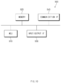
- FIG. 1 is a configuration diagram of a battery pack including a battery management device according to an embodiment of the present invention.
- a plurality of battery cells 2, 4, and 6 are connected in series or in parallel.
- Slave battery management systems 12, 14, and 16 are disposed in the battery cells 2, 4, and 6, respectively.
- the slave battery management systems 12, 14, and 16 respectively measure and monitor the temperature, voltage, or current of the plurality of battery cells 2, 4, and 6, and transmit monitored information to an upper-level system and control the connected battery cells by receiving a control command of the battery cell from the upper-level system.
- the plurality of battery cells 2, 4, and 6 are connected in series or in parallel to form a battery module 1.
- a master battery management system 10 is disposed in the battery module 1.
- the master battery management system 10 measures and monitors the temperature, voltage, or current of the battery module 1.
- the master battery management system 10 receives monitoring information of each battery cell from the slave battery management systems 12, 14, and 16 respectively disposed in the battery cells, and transmits the monitoring information to the upper system, and receives a specific task execution command from the upper-level system and transmits the specific task execution command to the corresponding slave battery management systems 12, 14, and 16.
- FIG. 2 is a block diagram illustrating a configuration of an upper-level controller according to an embodiment of the present invention.
- an upper-level controller 200 may include a communication unit 210, a control unit 220, and a memory unit 230.
- the upper-level controller 200 may be, for example, the master battery management system (BMS) described above.
- BMS master battery management system
- the communication unit 210 may transmit a command signal to the lower-level controller and receive a response signal to the command signal from the lower-level controller 220.
- the communication unit 210 may transmit and receive signals to and from all the lower-level controllers 220 in a broadcast manner.
- the upper-level controller 210 may repeatedly transmit the same signal several times during a fixed period so that the lower-level controller 220 that fails to receive the signal does not occur.
- the communication unit 210 may assign a unique identification ID to each lower-level controller. Accordingly, the upper-level controller 200 may distinguish which signal is transmitted from which lower-level controller through the unique identification ID.
- the command signal transmitted by the communication unit 210 may include identification information ID unique to signal, identification information on the number of repetitions of the signal, and information on battery state measurement.
- the communication unit 210 of the upper-level controller 200 generally repeatedly transmits a signal during a fixed period, and the transmitted command signal includes information on the number of times the signal is repeatedly transmitted during the corresponding period.
- the information on the battery state measurement of the command signal may include a trigger signal for measuring a state of the battery module.
- the controller 220 may select an intermediate lower-level controller based on strength of the response signal received from the lower-level controller.
- the strength of the received response signal may be a received signal strength indication (RSSI) value.
- RSSI received signal strength indication
- the controller 220 may select a lower-level controller whose strength of a response signal received from the lower-level controller is equal to or greater than a preset reference value (first reference value) as the intermediate lower-level controller.
- control unit 220 may assign priority to the lower-level controller in order in which the strength of the response signal received from the lower-level controller is high, and select a lower-level controller, whose priority is equal to or greater than a preset priority, among the lower-level controllers as the intermediate lower-level controller.
- the memory unit 230 may store information on a command signal transmitted from the upper-level controller 200 to the lower-level controller, information on a unique identification ID of the lower-level controller, and battery state data received from the lower-level controller.
- FIG. 3 is a block diagram illustrating a configuration of a lower-level controller according to an embodiment of the present invention.
- a lower-level controller 300 may include a communication unit 310, a control unit 320, and a memory unit 330.
- the lower-level controller 300 may be the slave battery management system (BMS) described above.
- BMS slave battery management system
- the intermediate lower-level controller is selected from among the lower-level controllers 300 according to a predetermined criterion and is included in the lower-level controller 300.
- the communication unit 310 may transmit a response signal to the command signal received from the upper-level controller 200 to the upper-level controller 200. Also, in the case of the intermediate lower-level controller, when the strength of the command signal received from the upper-level controller 200 is less than a preset reference value (second reference value), the communication unit 310 may transmit a signal corresponding to the command signal transmitted by the upper-level controller 200 with maximum power to the remaining lower-level controllers 300.
- the intermediate lower-level controller is not necessarily limited to transmitting a signal corresponding to the command signal with maximum power, and it would also be possible for an intermediate lower controller to transmit a signal with the magnitude equal to or greater than a predetermined reference value.
- the communication unit 310 of the intermediate lower-level controller may transmit a signal corresponding to the command signal transmitted by the upper controller 200 with maximum power.
- the communication unit 310 of the intermediate lower-level controller may transmit the signal, which corresponds to the command signal transmitted by the upper-level controller 200, as many times as the remaining number of times obtained by subtracting the number of times of not receiving or less than the second reference value from the preset number of times of repetition to the remaining lower controllers 300 with maximum power.
- the control unit 320 may perform an operation according to a command signal received from the upper-level controller 200. That is, when the control unit 320 receives a command signal for measuring the battery state from the host controller 200, the control unit 320 may monitor the voltage, temperature, and state of charge of the battery, and transmit a resulting response signal of monitoring to the upper-level controller 200 again through the communication unit 310.
- the memory unit 330 may accumulate and store the strength of the command signal received from the upper-level controller 200. Accordingly, the control unit 320 may determine the reference value (second reference value) based on a median value or an average value of the strength of the stored command signal.
- the intermediate lower-level controller transmits a signal corresponding to the command signal received from the upper-level controller 200 to the remaining lower-level controller 300 with maximum power, thereby capable of preventing a situation in which the remaining lower-level controllers 300 (e.g., lower-level controllers 300 far from the upper-level controller 200) do not receive a command signal from occurring even when a communication fault occurs.
- the remaining lower-level controllers 300 e.g., lower-level controllers 300 far from the upper-level controller 200
- FIGS. 2 and 3 the description is made in such a way that the upper-level controller 200 transmits the command signal to the remaining lower-level controller 300 through the intermediate lower-level controller 300, but is not limited thereto. On the contrary, a method of transmitting the response signals from the remaining lower-level controllers 300 to the upper-level controller 200 through the intermediate lower-level controller may also be possible.
- FIG. 4 is a diagram illustrating a communication method of a conventional battery management device.
- signals are transmitted and received between one upper-level controller (master BMS) and a plurality of lower-level controllers (slave BMS) on a one-to-one basis (broadcast method).
- the upper-level controller performs communication in such a way of transmitting a command signal for measuring the state of the battery to each lower-level controller and receiving a response signal to the command from each lower-level controller again.
- one upper-level controller assigns a unique identification ID to each lower controller when connection with all the lower-level controllers is complete.
- the assigned ID is included in the response signal packet of the lower-level controllers, and thus a packet structure is formed so that all the lower-level controllers, including the upper-level controller that receives the response packet, can recognize from which lower-level controller the response packet has been received.
- FIG. 5 is a diagram illustrating transmission and reception of signals between the master device and the slave devices over time in the conventional battery management device.
- the upper-level controller transmits a command signal (e.g., a Measure Trigger signal) several times at a fixed period, thereby minimizing lower-level controllers that fail to receive a signal.
- a command signal e.g., a Measure Trigger signal
- the upper-level controller may transmit the command signal to the lower-level controller as many times as the number of communication protocols promised in advance.
- the lower-level controllers may repeatedly transmit the response signal including measurement data to the upper-level controller at a fixed period allocated according to their respective order. Even in this case, the lower-level controllers may transmit a command signal to the upper-level controller as many times as the number of communication protocols promised in advance.
- the upper-level controller transmits a command signal three times at intervals of 2 ms for a period of 5.5 ms (T_Request).
- each lower-level controller that has received the command signal may measure the state of the battery for 3 ms (T_Measure), and transmit a response signal thereto three times at intervals of 2.8 ms for a period of 7.6 ms (T_Slave_Slot).
- a signal transmission and reception period (T_Cycle) between the upper-level controller and the lower-level controllers becomes T_Request + T_Measure + T_Response (T_Slave_Slot*N) as illustrated in FIG. 5 .
- FIG. 6 is a diagram illustrating transmission and reception of signals between a master device and slave devices over time in a battery management device according to an embodiment of the present invention.
- the signal transmission and reception period and the number of repetitions of the upper-level controller and the lower-level controllers are the same as those of FIG. 5 , a detailed description thereof will be omitted.
- FIG. 6 illustrates a method of communicating between the upper-level controller and the lower-level controllers when Slave_1 and Slave_2 among the lower-level controllers are selected as the intermediate lower-level controllers of FIG. 1 .
- Slave_1 and Slave_2 which are the intermediate lower-level controllers, may be selected based on the strength of the response signal received by the upper-level controller from the lower-level controllers.
- the upper-level controller may select a lower-level controller whose strength of the response signal received from the lower-level controller is equal to or greater than a reference value (first reference value) as the intermediate lower-level controller.
- the upper-level controller may assign priority to the lower-level controller in order in which the strength of the response signal received from the lower-level controller is high, and select a lower-level controller, whose priority is equal to or greater than a preset priority, among the lower-level controllers as the intermediate lower-level controller.
- a signal corresponding to the command signal received from the upper-level controller may be transmitted with maximum power to the remaining lower-level controllers (i.e., Slave_3 to Slave_N).
- Slave_1 and Slave_2 may accumulate and store the strength of the command signal received from the upper-level controller, and may determine the reference value (second reference value) based on a median value or an average value of the strength of the stored command signal.
- Slave_1 and Slave_2 which are the intermediate lower-level controllers, fail to receive the command signal as many times as the preset number of times of repetition during the preset period from the upper-level controller, Slave_1 and Slave_2 may transmit a signal corresponding to the command signal received from the upper-level controller with maximum power.
- Slave_1 and Slave_2 may not receive a signal corresponding to the command signal received from the upper-level controller at a prescribed number of times with the upper-level controller, or may transmit to the remaining lower-level controllers with maximum power as many times as less than the second reference value.
- Slave_1 and Slave_2 may broadcast command signals with maximum power when transmitting the command signal to the remaining lower controllers Slave_3 to Slave_N for the second and third times.
- communication between the battery management systems can be made in good condition by performing wireless communication using the intermediate node even when a communication fault occurs between nodes.
- the communication periods or times (e.g., T_Request, T_Measure, T_Slave_Slot, etc.) illustrated in FIGS. 5 and 6 are illustrated as examples for the description of the present invention, and the present invention is not limited to these periods or times. That is, the communication period or time of the battery management device according to the embodiment of the present invention may be set in various ways according to a packet size and a communication environment.
- FIG. 7 is a diagram illustrating a packet of a signal transmitted from the master device (upper-level controller) according to an embodiment of the present invention.
- the command signal of the upper-level controller may include a header 610, Measure Trigger identification information 620, Measure Trigger repetition number identification information 630, and command information 640 including balancing, etc.
- the header 610 is a character group placed at the top of the command signal and may function to identify or control the contents and characteristics of data included in the signal.
- the Measure Trigger identification information 620 makes it possible to identify Measure Trigger at a specific timing and previous Measure Triggers.
- the Measure Trigger identification information 620 may include the unique identification ID of the signal described above.
- the Measure Trigger repetition number identification information 630 may include information on a transmission period of a signal and the number of repetitions during the transmission period so as to detect omission of the number of repetitions of the signal transmitted and received by the upper or lower-level controller during a fixed period.
- the command information 640 including Balancing, etc. may include information on measuring the state of the battery (e.g., information on measuring the voltage, temperature, SOC, etc. of the battery), and information on balancing of each battery cell (e.g., balancing cycle, information about voltage, etc.).
- FIG. 8 is a flowchart illustrating a battery management method according to an embodiment of the present invention.
- a command signal is transmitted from an upper-level controller to a lower-level controller (S710).
- the upper-level controller may include a Measure Trigger signal that causes the lower-level controller to measure the state of the battery.
- the lower-level controller receiving the command signal performs an operation according to the command signal received from the upper-level controller (S720).
- the lower-level controller may monitor the states such as voltage, temperature, and SOC of the battery according to the command signal from the upper-level controller.
- the lower-level controller transmits a response signal to the command signal to the upper-level controller (S730).
- the response signal transmitted to the upper-level controller may include result data regarding the states such as the voltage, temperature, and SOC of the battery.
- the upper-level controller that has received the response signal selects an intermediate lower-level controller according to a predetermined criterion among the lower-level controllers.
- the upper-level controller may select the intermediate lower-level controller based on the strength of the response signal received from the lower-level controller (S740).
- the upper-level controller may select a lower-level controller whose strength of the response signal received from the lower-level controller is equal to or greater than a preset reference value (first reference value) as the intermediate lower-level controller.
- first reference value a preset reference value
- the upper-level controller may assign priority to the lower-level controller in order in which the strength of the response signal received from the lower-level controller is high, and select a lower-level controller, whose priority is equal to or greater than a preset priority, among the lower-level controllers as the intermediate lower-level controller.
- the intermediate lower-level controller determines whether or not the strength of the command signal received from the upper-level controller is equal to or greater than a preset reference value (second reference value) (S750). If the strength of the command signal received from upper-level controller is equal to or greater than the preset reference value (second reference value) (YES), since there is no communication fault, the intermediate lower-level controller may transmit a signal corresponding to the command signal received from the upper-level controller with basic power to other lower-level controllers (S760).
- a preset reference value second reference value
- the intermediate lower-level controller transmits the signal corresponding to the command signal received from the upper-level controller with maximum power to other lower-level controllers (S770).
- the intermediate lower-level controller need not necessarily transmit a signal with maximum power, and may transmit a signal with power equal to or greater than a predetermined reference value.
- FIG. 9 is a flowchart illustrating a battery management method according to another embodiment of the present invention.
- Steps S810 to S840 of FIG. 9 are substantially the same as steps S710 to S740 of FIG. 8 , and thus the detailed description thereof will be omitted.
- the intermediate lower-level controller determines whether or not a command signal has been received from the upper-level controller as many times as a preset number of times of repetition during a fixed period (S850).
- the intermediate lower-level controller may transmit the command signal to other controllers with basic power (SS60).
- the intermediate lower-level controller transmits the command signal to other controllers with maximum power (S870).
- the intermediate lower-level controller may transmit a signal corresponding to the command signal received from the upper controller as many times as the remaining number of times obtained by subtracting the number of times (or less than the reference value (second reference value)) the command signal is not received from the preset number of times of repetition to the remaining lower controllers with maximum power.
- the battery management method it is possible to enable good communication between battery management systems by performing wireless communication using an intermediate node even when a communication fault occurs between nodes.
- FIG. 10 is a diagram illustrating a hardware configuration of a battery management device according to an embodiment of the present invention.
- a battery management device 900 may include a microcontroller (MCU) 910 that controls various processing and each configuration, a memory 920 in which an operating system program and various programs (e.g., a battery pack abnormality diagnosis program or a battery pack temperature estimation program) are recorded, an input/output interface 930 that provides input interface and output interface between a battery cell module and/or a switching unit (e.g., a semiconductor switching device), and a communication interface 940 capable of communicating with the outside (for example, an upper-level controller) through a wired or wireless communication network.
- a computer program according to the present invention may be recorded in the memory 920 and processed by the microcontroller 910, thereby capable of being implemented as, for example, a module that performs each functional block illustrated in FIG. 2 .
Landscapes
- Engineering & Computer Science (AREA)
- Chemical & Material Sciences (AREA)
- General Chemical & Material Sciences (AREA)
- Electrochemistry (AREA)
- Chemical Kinetics & Catalysis (AREA)
- Manufacturing & Machinery (AREA)
- Microelectronics & Electronic Packaging (AREA)
- Computer Networks & Wireless Communication (AREA)
- Physics & Mathematics (AREA)
- General Physics & Mathematics (AREA)
- Quality & Reliability (AREA)
- Electromagnetism (AREA)
- Signal Processing (AREA)
- Charge And Discharge Circuits For Batteries Or The Like (AREA)
- Secondary Cells (AREA)
- Mobile Radio Communication Systems (AREA)
Claims (11)
- Dispositif de gestion de batterie (900) comprenant :un dispositif de commande de niveau supérieur (200) configuré pour transmettre un signal d'instruction à un dispositif de commande de niveau inférieur et recevoir du dispositif de commande de niveau inférieur un signal de réponse au signal d'instruction ; etun dispositif de commande de niveau inférieur (300) configuré pour réaliser une opération selon le signal d'instruction reçu du dispositif de commande de niveau supérieur, et transmettre au dispositif de commande de niveau supérieur le signal de réponse au signal d'instruction,caractérisé parun dispositif de commande de niveau inférieur (300) intermédiaire sélectionné parmi les dispositifs de commande de niveau inférieur selon un critère prédéterminé,configuré pour transmettre au reste des dispositifs de commande de niveau inférieur un signal correspondant au signal d'instruction transmis par le dispositif de commande de niveau supérieur avec une puissance maximale, lorsqu'une force du signal d'instruction reçu du dispositif de commande de niveau supérieur satisfait à une condition prédéfinie.
- Dispositif selon la revendication 1,
dans lequel le dispositif de commande de niveau supérieur est configuré pour sélectionner le dispositif de commande de niveau inférieur intermédiaire sur la base de la force du signal de réponse reçu du dispositif de commande de niveau inférieur. - Dispositif selon la revendication 2,
dans lequel le dispositif de commande de niveau supérieur est configuré pour sélectionner un dispositif de commande de niveau inférieur dont la force du signal de réponse reçu du dispositif de commande de niveau inférieur est égale ou supérieure à une première valeur de référence prédéfinie en tant que dispositif de commande de niveau inférieur intermédiaire. - Dispositif selon la revendication 2,
dans lequel le dispositif de commande de niveau supérieur est configuré pour attribuer une priorité au dispositif de commande de niveau inférieur dans un ordre où la force du signal de réponse reçu du dispositif de commande de niveau inférieur est élevée, et pour sélectionner parmi les dispositifs de commande de niveau inférieur un dispositif de commande de niveau inférieur dont la priorité est égale ou supérieure à une priorité prédéfinie en tant que dispositif de commande de niveau inférieur intermédiaire. - Dispositif selon la revendication 1,
dans lequel le dispositif de commande de niveau inférieur intermédiaire est configuré pour transmettre au reste des dispositifs de commande de niveau inférieur un signal correspondant au signal d'instruction transmis par le dispositif de commande de niveau supérieur avec une puissance maximale, lorsque la force du signal d'instruction reçu du dispositif de commande de niveau supérieur est inférieure à une deuxième valeur de référence prédéfinie. - Dispositif selon la revendication 5,
dans lequel le dispositif de commande de niveau inférieur intermédiaire est configuré pour accumuler et stocker la force du signal d'instruction reçu du dispositif de commande de niveau supérieur, et pour déterminer la deuxième valeur de référence sur la base d'une valeur médiane ou d'une valeur moyenne de la force du signal d'instruction stocké. - Dispositif selon la revendication 1,dans lequel le dispositif de commande de niveau supérieur est défini pour transmettre le signal d'instruction autant de fois qu'un nombre prédéfini de fois de répétition au cours d'une période prédéfinie, etle dispositif de commande de niveau inférieur intermédiaire est configuré pour transmettre un signal correspondant au signal d'instruction transmis par le dispositif de commande de niveau supérieur avec une puissance maximale lorsque le signal d'instruction n'est pas reçu du dispositif de commande de niveau supérieur autant de fois que le nombre prédéfini de fois de répétition pendant la période prédéfinie.
- Dispositif selon la revendication 7,
dans lequel, lorsque le signal d'instruction n'est pas reçu du dispositif de commande de niveau supérieur autant de fois que le nombre prédéfini de fois de répétition pendant la période prédéfinie ou que la force du signal d'instruction reçu est inférieure à la deuxième valeur de référence prédéfinie, le dispositif de commande de niveau inférieur intermédiaire est configuré pour transmettre au reste des dispositifs inférieurs le signal d'instruction autant de fois que le nombre de fois restant obtenu en soustrayant le nombre de fois de non-réception ou d'infériorité à la deuxième valeur de référence du nombre prédéfini de fois de répétition, avec une puissance maximale. - Dispositif selon la revendication 1,
dans lequel le signal d'instruction et le signal de réponse comportent au moins une parmi une information d'identification spécifiques au signal, une information d'identification sur le nombre de répétitions du signal et une information sur une mesure d'état de batterie. - Dispositif selon la revendication 1,
dans lequel le signal d'instruction comporte un signal de déclenchement pour mesurer un état d'un module de batterie. - Procédé de gestion de batterie comprenant :la transmission d'un signal d'instruction d'un dispositif de commande de niveau supérieur (200) à un dispositif de commande de niveau inférieur (300) ;la réalisation, par le dispositif de commande de niveau inférieur, d'une opération selon le signal d'instruction reçu du dispositif de commande de niveau supérieur ;la transmission au dispositif de commande de niveau supérieur, par le dispositif de commande de niveau inférieur, d'un signal de réponse au signal d'instruction ;la sélection parmi les dispositifs de commande de niveau inférieur, par le dispositif de commande de niveau supérieur, d'un dispositif de commande de niveau inférieur (300) intermédiaire, selon un critère prédéterminé ; etla transmission au reste des dispositifs de commande de niveau inférieur, par le dispositif de commande de niveau inférieur intermédiaire, d'un signal correspondant au signal d'instruction transmis par le dispositif de commande de niveau supérieur avec une puissance maximale, lorsqu'une force du signal d'instruction reçu du dispositif de commande de niveau supérieur satisfait à une condition prédéfinie.
Applications Claiming Priority (2)
| Application Number | Priority Date | Filing Date | Title |
|---|---|---|---|
| KR1020190111783A KR20210030168A (ko) | 2019-09-09 | 2019-09-09 | 중간 노드를 이용하여 통신하는 배터리 관리 시스템 및 방법 |
| PCT/KR2020/012071 WO2021049838A1 (fr) | 2019-09-09 | 2020-09-07 | Système de gestion de batterie et procédé de communication utilisant un nœud intermédiaire |
Publications (3)
| Publication Number | Publication Date |
|---|---|
| EP3937290A1 EP3937290A1 (fr) | 2022-01-12 |
| EP3937290A4 EP3937290A4 (fr) | 2022-08-17 |
| EP3937290B1 true EP3937290B1 (fr) | 2023-08-16 |
Family
ID=74867293
Family Applications (1)
| Application Number | Title | Priority Date | Filing Date |
|---|---|---|---|
| EP20863211.7A Active EP3937290B1 (fr) | 2019-09-09 | 2020-09-07 | Système de gestion de batterie et procédé pour communiquer utilisant un noeud intermédiaire |
Country Status (6)
| Country | Link |
|---|---|
| US (1) | US20220179001A1 (fr) |
| EP (1) | EP3937290B1 (fr) |
| JP (1) | JP7244033B2 (fr) |
| KR (1) | KR20210030168A (fr) |
| CN (1) | CN113875064B (fr) |
| WO (1) | WO2021049838A1 (fr) |
Families Citing this family (6)
| Publication number | Priority date | Publication date | Assignee | Title |
|---|---|---|---|---|
| US11872905B2 (en) | 2021-04-16 | 2024-01-16 | Texas Instruments Incorporated | Wireless protocol for battery management |
| US11736928B2 (en) * | 2021-05-07 | 2023-08-22 | Texas Instruments Incorporated | Wireless management of modular subsystems with proxy node options |
| JP2023028156A (ja) * | 2021-08-18 | 2023-03-03 | 日立Astemo株式会社 | 管理装置、バッテリデータ伝送装置、伝送システム |
| US20230063402A1 (en) * | 2021-08-30 | 2023-03-02 | Texas Instruments Incorporated | Determining super frame packet generation times |
| US11812268B2 (en) | 2021-09-30 | 2023-11-07 | Texas Instruments Incorporated | Data integrity options for wireless management of modular subsystems |
| WO2024013373A1 (fr) * | 2022-07-15 | 2024-01-18 | Marposs Societa' Per Azioni | Plateau pour loger un groupe de cellules électrochimiques et installation de fabrication utilisant le plateau |
Family Cites Families (16)
| Publication number | Priority date | Publication date | Assignee | Title |
|---|---|---|---|---|
| JPH08139660A (ja) * | 1994-11-14 | 1996-05-31 | Fuji Electric Co Ltd | 中継を伴う一斉同報通信システムの中継局指定方法 |
| JPH0923279A (ja) * | 1995-07-05 | 1997-01-21 | Tokyo Gas Co Ltd | 無線通信システム |
| JP3648974B2 (ja) * | 1998-03-10 | 2005-05-18 | オムロン株式会社 | 無線通信装置 |
| JP4605952B2 (ja) * | 2001-08-29 | 2011-01-05 | 株式会社日立製作所 | 蓄電装置及びその制御方法 |
| JP5466586B2 (ja) * | 2009-10-05 | 2014-04-09 | プライムアースEvエナジー株式会社 | 組電池の管理装置 |
| KR101891843B1 (ko) * | 2010-11-02 | 2018-09-28 | 나비타스 솔루션스, 아이엔씨. | 스마트 배터리 관리를 위한 무선 배터리 에어리어 네트웍 |
| KR101631064B1 (ko) * | 2012-08-06 | 2016-06-16 | 삼성에스디아이 주식회사 | 배터리 팩의 전압 측정 방법 및 이를 포함하는 에너지 저장 시스템 |
| WO2015063945A1 (fr) * | 2013-11-01 | 2015-05-07 | 株式会社日立製作所 | Système de commande de batterie |
| GB201523108D0 (en) * | 2015-12-30 | 2016-02-10 | Hyperdrive Innovation Ltd | Battery management system |
| KR102179680B1 (ko) * | 2016-03-03 | 2020-11-17 | 주식회사 엘지화학 | 배터리 시스템의 셀 타입 자동 설정 방법 |
| CN106532163A (zh) * | 2016-11-15 | 2017-03-22 | 上海玖行能源科技有限公司 | 一种电池管理系统 |
| CN108736077B (zh) * | 2017-04-18 | 2020-09-18 | 奥动新能源汽车科技有限公司 | 电池管理系统的从控制器的配置方法和配置系统 |
| KR102155331B1 (ko) * | 2017-07-06 | 2020-09-11 | 주식회사 엘지화학 | 무선 배터리 관리 시스템 및 이를 포함하는 배터리팩 |
| KR102164547B1 (ko) * | 2017-07-31 | 2020-10-12 | 주식회사 엘지화학 | 배터리 관리 장치 및 이를 포함하는 배터리 팩 |
| JP6886903B2 (ja) * | 2017-09-15 | 2021-06-16 | ラピスセミコンダクタ株式会社 | 電池監視装置及び電池監視システム |
| KR102474424B1 (ko) * | 2017-10-31 | 2022-12-05 | 주식회사 엘엑스세미콘 | 마스터 콘트롤러와 슬레이브 콘트롤러들 간의 통신 방법, 그를 위한 슬레이브 콘트롤러, 및 그를 이용한 배터리 관리 시스템 |
-
2019
- 2019-09-09 KR KR1020190111783A patent/KR20210030168A/ko active Search and Examination
-
2020
- 2020-09-07 US US17/601,591 patent/US20220179001A1/en active Pending
- 2020-09-07 CN CN202080031111.2A patent/CN113875064B/zh active Active
- 2020-09-07 EP EP20863211.7A patent/EP3937290B1/fr active Active
- 2020-09-07 WO PCT/KR2020/012071 patent/WO2021049838A1/fr unknown
- 2020-09-07 JP JP2021549341A patent/JP7244033B2/ja active Active
Also Published As
| Publication number | Publication date |
|---|---|
| EP3937290A4 (fr) | 2022-08-17 |
| KR20210030168A (ko) | 2021-03-17 |
| JP2022521927A (ja) | 2022-04-13 |
| US20220179001A1 (en) | 2022-06-09 |
| EP3937290A1 (fr) | 2022-01-12 |
| CN113875064B (zh) | 2024-05-17 |
| CN113875064A (zh) | 2021-12-31 |
| WO2021049838A1 (fr) | 2021-03-18 |
| JP7244033B2 (ja) | 2023-03-22 |
Similar Documents
| Publication | Publication Date | Title |
|---|---|---|
| EP3937290B1 (fr) | Système de gestion de batterie et procédé pour communiquer utilisant un noeud intermédiaire | |
| US11038216B2 (en) | Wireless battery management system and battery pack including same | |
| EP3547705A1 (fr) | Gestion de batterie tolérante aux pannes | |
| JP6421625B2 (ja) | 無線電池システムおよび無線システム | |
| JP2020504422A (ja) | マスターバッテリー管理ユニット及びこれを含むバッテリーパック | |
| JP2020504421A (ja) | バッテリー管理ユニット及びこれを含むバッテリーパック | |
| US11483824B2 (en) | Wireless battery management system, node for wireless communication, and method of transmitting data | |
| KR20220013137A (ko) | 통신 오류의 원인을 진단하기 위한 슬레이브 bms, 마스터 bms 및 배터리 팩 | |
| JP7228704B2 (ja) | 蓄電池装置 | |
| US20220247841A1 (en) | Battery management system and method for transmitting data to higher-level system | |
| KR20200098071A (ko) | 슬레이브 bms 점검 시스템 및 방법 | |
| KR20200144053A (ko) | 무선 배터리 관리 시스템과 무선통신을 위한 노드 및 데이터 전송 방법 | |
| EP4064415A1 (fr) | Système et procédé de détection de batterie défectueuse utilisant une communication sans fil | |
| US11310720B2 (en) | Wireless battery management system, node for wireless communication, and network establishment method | |
| CN104662927A (zh) | 用于在具有多个电池的电池组系统处进行数据传送的方法 | |
| US20220394438A1 (en) | Sensor System, Wireless Cooperative Receiving System, and Wireless Cooperative Receiving Method | |
| CN116080401A (zh) | 动态可重新配置的电池管理架构 | |
| US20230101736A1 (en) | Slave BMS for Diagnosing an Error of a Battery Module and Battery Pack Comprising Same Slave BMS | |
| KR20210027092A (ko) | 무선 배터리 관리 시스템과 이를 위한 매니저 노드 및 채널 운영 방법 | |
| EP4083645A1 (fr) | Dispositif et procédé d'approvisionnement pour diagnostic d'état de batterie et attribution d'id | |
| US11831464B2 (en) | Network routing device and method | |
| US20170346712A1 (en) | Coordination of serving access nodes in serving cluster | |
| US20240072841A1 (en) | Adaptive frequency hopping in a wireless battery management system | |
| KR20200144376A (ko) | Bms id 할당 장치 및 방법 | |
| Hartmann et al. | Network-capable smart batteries for smart grid and battery management systems |
Legal Events
| Date | Code | Title | Description |
|---|---|---|---|
| STAA | Information on the status of an ep patent application or granted ep patent |
Free format text: STATUS: THE INTERNATIONAL PUBLICATION HAS BEEN MADE |
|
| PUAI | Public reference made under article 153(3) epc to a published international application that has entered the european phase |
Free format text: ORIGINAL CODE: 0009012 |
|
| STAA | Information on the status of an ep patent application or granted ep patent |
Free format text: STATUS: REQUEST FOR EXAMINATION WAS MADE |
|
| 17P | Request for examination filed |
Effective date: 20211007 |
|
| AK | Designated contracting states |
Kind code of ref document: A1 Designated state(s): AL AT BE BG CH CY CZ DE DK EE ES FI FR GB GR HR HU IE IS IT LI LT LU LV MC MK MT NL NO PL PT RO RS SE SI SK SM TR |
|
| RAP3 | Party data changed (applicant data changed or rights of an application transferred) |
Owner name: LG ENERGY SOLUTION, LTD. |
|
| A4 | Supplementary search report drawn up and despatched |
Effective date: 20220715 |
|
| RIC1 | Information provided on ipc code assigned before grant |
Ipc: H04B 17/318 20150101ALI20220711BHEP Ipc: G01R 31/371 20190101ALI20220711BHEP Ipc: H01M 10/48 20060101ALI20220711BHEP Ipc: H01M 10/42 20060101ALI20220711BHEP Ipc: H04Q 9/00 20060101AFI20220711BHEP |
|
| DAV | Request for validation of the european patent (deleted) | ||
| DAX | Request for extension of the european patent (deleted) | ||
| REG | Reference to a national code |
Ref document number: 602020015988 Country of ref document: DE Ref country code: DE Ref legal event code: R079 Free format text: PREVIOUS MAIN CLASS: H01M0010420000 Ipc: H04Q0009000000 |
|
| RIC1 | Information provided on ipc code assigned before grant |
Ipc: H04B 17/318 20150101ALI20230119BHEP Ipc: G01R 31/371 20190101ALI20230119BHEP Ipc: H01M 10/48 20060101ALI20230119BHEP Ipc: H01M 10/42 20060101ALI20230119BHEP Ipc: H04Q 9/00 20060101AFI20230119BHEP |
|
| GRAP | Despatch of communication of intention to grant a patent |
Free format text: ORIGINAL CODE: EPIDOSNIGR1 |
|
| STAA | Information on the status of an ep patent application or granted ep patent |
Free format text: STATUS: GRANT OF PATENT IS INTENDED |
|
| INTG | Intention to grant announced |
Effective date: 20230421 |
|
| P01 | Opt-out of the competence of the unified patent court (upc) registered |
Effective date: 20230516 |
|
| GRAS | Grant fee paid |
Free format text: ORIGINAL CODE: EPIDOSNIGR3 |
|
| GRAA | (expected) grant |
Free format text: ORIGINAL CODE: 0009210 |
|
| STAA | Information on the status of an ep patent application or granted ep patent |
Free format text: STATUS: THE PATENT HAS BEEN GRANTED |
|
| AK | Designated contracting states |
Kind code of ref document: B1 Designated state(s): AL AT BE BG CH CY CZ DE DK EE ES FI FR GB GR HR HU IE IS IT LI LT LU LV MC MK MT NL NO PL PT RO RS SE SI SK SM TR |
|
| REG | Reference to a national code |
Ref country code: CH Ref legal event code: EP |
|
| REG | Reference to a national code |
Ref country code: DE Ref legal event code: R096 Ref document number: 602020015988 Country of ref document: DE |
|
| REG | Reference to a national code |
Ref country code: IE Ref legal event code: FG4D |
|
| PGFP | Annual fee paid to national office [announced via postgrant information from national office to epo] |
Ref country code: FR Payment date: 20230821 Year of fee payment: 4 Ref country code: DE Payment date: 20230822 Year of fee payment: 4 |
|
| REG | Reference to a national code |
Ref country code: LT Ref legal event code: MG9D |
|
| REG | Reference to a national code |
Ref country code: NL Ref legal event code: MP Effective date: 20230816 |
|
| REG | Reference to a national code |
Ref country code: AT Ref legal event code: MK05 Ref document number: 1601256 Country of ref document: AT Kind code of ref document: T Effective date: 20230816 |
|
| PG25 | Lapsed in a contracting state [announced via postgrant information from national office to epo] |
Ref country code: GR Free format text: LAPSE BECAUSE OF FAILURE TO SUBMIT A TRANSLATION OF THE DESCRIPTION OR TO PAY THE FEE WITHIN THE PRESCRIBED TIME-LIMIT Effective date: 20231117 |
|
| PG25 | Lapsed in a contracting state [announced via postgrant information from national office to epo] |
Ref country code: IS Free format text: LAPSE BECAUSE OF FAILURE TO SUBMIT A TRANSLATION OF THE DESCRIPTION OR TO PAY THE FEE WITHIN THE PRESCRIBED TIME-LIMIT Effective date: 20231216 |
|
| PG25 | Lapsed in a contracting state [announced via postgrant information from national office to epo] |
Ref country code: SE Free format text: LAPSE BECAUSE OF FAILURE TO SUBMIT A TRANSLATION OF THE DESCRIPTION OR TO PAY THE FEE WITHIN THE PRESCRIBED TIME-LIMIT Effective date: 20230816 Ref country code: RS Free format text: LAPSE BECAUSE OF FAILURE TO SUBMIT A TRANSLATION OF THE DESCRIPTION OR TO PAY THE FEE WITHIN THE PRESCRIBED TIME-LIMIT Effective date: 20230816 Ref country code: PT Free format text: LAPSE BECAUSE OF FAILURE TO SUBMIT A TRANSLATION OF THE DESCRIPTION OR TO PAY THE FEE WITHIN THE PRESCRIBED TIME-LIMIT Effective date: 20231218 Ref country code: NO Free format text: LAPSE BECAUSE OF FAILURE TO SUBMIT A TRANSLATION OF THE DESCRIPTION OR TO PAY THE FEE WITHIN THE PRESCRIBED TIME-LIMIT Effective date: 20231116 Ref country code: NL Free format text: LAPSE BECAUSE OF FAILURE TO SUBMIT A TRANSLATION OF THE DESCRIPTION OR TO PAY THE FEE WITHIN THE PRESCRIBED TIME-LIMIT Effective date: 20230816 Ref country code: LV Free format text: LAPSE BECAUSE OF FAILURE TO SUBMIT A TRANSLATION OF THE DESCRIPTION OR TO PAY THE FEE WITHIN THE PRESCRIBED TIME-LIMIT Effective date: 20230816 Ref country code: LT Free format text: LAPSE BECAUSE OF FAILURE TO SUBMIT A TRANSLATION OF THE DESCRIPTION OR TO PAY THE FEE WITHIN THE PRESCRIBED TIME-LIMIT Effective date: 20230816 Ref country code: IS Free format text: LAPSE BECAUSE OF FAILURE TO SUBMIT A TRANSLATION OF THE DESCRIPTION OR TO PAY THE FEE WITHIN THE PRESCRIBED TIME-LIMIT Effective date: 20231216 Ref country code: HR Free format text: LAPSE BECAUSE OF FAILURE TO SUBMIT A TRANSLATION OF THE DESCRIPTION OR TO PAY THE FEE WITHIN THE PRESCRIBED TIME-LIMIT Effective date: 20230816 Ref country code: GR Free format text: LAPSE BECAUSE OF FAILURE TO SUBMIT A TRANSLATION OF THE DESCRIPTION OR TO PAY THE FEE WITHIN THE PRESCRIBED TIME-LIMIT Effective date: 20231117 Ref country code: FI Free format text: LAPSE BECAUSE OF FAILURE TO SUBMIT A TRANSLATION OF THE DESCRIPTION OR TO PAY THE FEE WITHIN THE PRESCRIBED TIME-LIMIT Effective date: 20230816 Ref country code: AT Free format text: LAPSE BECAUSE OF FAILURE TO SUBMIT A TRANSLATION OF THE DESCRIPTION OR TO PAY THE FEE WITHIN THE PRESCRIBED TIME-LIMIT Effective date: 20230816 |
|
| PG25 | Lapsed in a contracting state [announced via postgrant information from national office to epo] |
Ref country code: PL Free format text: LAPSE BECAUSE OF FAILURE TO SUBMIT A TRANSLATION OF THE DESCRIPTION OR TO PAY THE FEE WITHIN THE PRESCRIBED TIME-LIMIT Effective date: 20230816 |
|
| PG25 | Lapsed in a contracting state [announced via postgrant information from national office to epo] |
Ref country code: ES Free format text: LAPSE BECAUSE OF FAILURE TO SUBMIT A TRANSLATION OF THE DESCRIPTION OR TO PAY THE FEE WITHIN THE PRESCRIBED TIME-LIMIT Effective date: 20230816 |
|
| PG25 | Lapsed in a contracting state [announced via postgrant information from national office to epo] |
Ref country code: SM Free format text: LAPSE BECAUSE OF FAILURE TO SUBMIT A TRANSLATION OF THE DESCRIPTION OR TO PAY THE FEE WITHIN THE PRESCRIBED TIME-LIMIT Effective date: 20230816 Ref country code: RO Free format text: LAPSE BECAUSE OF FAILURE TO SUBMIT A TRANSLATION OF THE DESCRIPTION OR TO PAY THE FEE WITHIN THE PRESCRIBED TIME-LIMIT Effective date: 20230816 Ref country code: ES Free format text: LAPSE BECAUSE OF FAILURE TO SUBMIT A TRANSLATION OF THE DESCRIPTION OR TO PAY THE FEE WITHIN THE PRESCRIBED TIME-LIMIT Effective date: 20230816 Ref country code: EE Free format text: LAPSE BECAUSE OF FAILURE TO SUBMIT A TRANSLATION OF THE DESCRIPTION OR TO PAY THE FEE WITHIN THE PRESCRIBED TIME-LIMIT Effective date: 20230816 Ref country code: DK Free format text: LAPSE BECAUSE OF FAILURE TO SUBMIT A TRANSLATION OF THE DESCRIPTION OR TO PAY THE FEE WITHIN THE PRESCRIBED TIME-LIMIT Effective date: 20230816 Ref country code: CZ Free format text: LAPSE BECAUSE OF FAILURE TO SUBMIT A TRANSLATION OF THE DESCRIPTION OR TO PAY THE FEE WITHIN THE PRESCRIBED TIME-LIMIT Effective date: 20230816 Ref country code: SK Free format text: LAPSE BECAUSE OF FAILURE TO SUBMIT A TRANSLATION OF THE DESCRIPTION OR TO PAY THE FEE WITHIN THE PRESCRIBED TIME-LIMIT Effective date: 20230816 |
|
| REG | Reference to a national code |
Ref country code: CH Ref legal event code: PL |
|
| PG25 | Lapsed in a contracting state [announced via postgrant information from national office to epo] |
Ref country code: LU Free format text: LAPSE BECAUSE OF NON-PAYMENT OF DUE FEES Effective date: 20230907 |