EP3933486B1 - Mikromechanische spiegelvorrichtung - Google Patents
Mikromechanische spiegelvorrichtung Download PDFInfo
- Publication number
- EP3933486B1 EP3933486B1 EP21155073.6A EP21155073A EP3933486B1 EP 3933486 B1 EP3933486 B1 EP 3933486B1 EP 21155073 A EP21155073 A EP 21155073A EP 3933486 B1 EP3933486 B1 EP 3933486B1
- Authority
- EP
- European Patent Office
- Prior art keywords
- connecting spring
- plate
- mirror
- spring structures
- structures
- Prior art date
- Legal status (The legal status is an assumption and is not a legal conclusion. Google has not performed a legal analysis and makes no representation as to the accuracy of the status listed.)
- Active
Links
Images




Classifications
-
- G—PHYSICS
- G02—OPTICS
- G02B—OPTICAL ELEMENTS, SYSTEMS OR APPARATUS
- G02B26/00—Optical devices or arrangements for the control of light using movable or deformable optical elements
- G02B26/08—Optical devices or arrangements for the control of light using movable or deformable optical elements for controlling the direction of light
- G02B26/0816—Optical devices or arrangements for the control of light using movable or deformable optical elements for controlling the direction of light by means of one or more reflecting elements
- G02B26/0833—Optical devices or arrangements for the control of light using movable or deformable optical elements for controlling the direction of light by means of one or more reflecting elements the reflecting element being a micromechanical device, e.g. a MEMS mirror, DMD
-
- B—PERFORMING OPERATIONS; TRANSPORTING
- B81—MICROSTRUCTURAL TECHNOLOGY
- B81B—MICROSTRUCTURAL DEVICES OR SYSTEMS, e.g. MICROMECHANICAL DEVICES
- B81B3/00—Devices comprising flexible or deformable elements, e.g. comprising elastic tongues or membranes
- B81B3/0064—Constitution or structural means for improving or controlling the physical properties of a device
- B81B3/0067—Mechanical properties
- B81B3/0072—For controlling internal stress or strain in moving or flexible elements, e.g. stress compensating layers
-
- B—PERFORMING OPERATIONS; TRANSPORTING
- B81—MICROSTRUCTURAL TECHNOLOGY
- B81B—MICROSTRUCTURAL DEVICES OR SYSTEMS, e.g. MICROMECHANICAL DEVICES
- B81B2201/00—Specific applications of microelectromechanical systems
- B81B2201/04—Optical MEMS
- B81B2201/042—Micromirrors, not used as optical switches
-
- B—PERFORMING OPERATIONS; TRANSPORTING
- B81—MICROSTRUCTURAL TECHNOLOGY
- B81B—MICROSTRUCTURAL DEVICES OR SYSTEMS, e.g. MICROMECHANICAL DEVICES
- B81B2203/00—Basic microelectromechanical structures
- B81B2203/01—Suspended structures, i.e. structures allowing a movement
- B81B2203/0145—Flexible holders
- B81B2203/0154—Torsion bars
-
- B—PERFORMING OPERATIONS; TRANSPORTING
- B81—MICROSTRUCTURAL TECHNOLOGY
- B81B—MICROSTRUCTURAL DEVICES OR SYSTEMS, e.g. MICROMECHANICAL DEVICES
- B81B2203/00—Basic microelectromechanical structures
- B81B2203/01—Suspended structures, i.e. structures allowing a movement
- B81B2203/0145—Flexible holders
- B81B2203/0163—Spring holders
-
- B—PERFORMING OPERATIONS; TRANSPORTING
- B81—MICROSTRUCTURAL TECHNOLOGY
- B81B—MICROSTRUCTURAL DEVICES OR SYSTEMS, e.g. MICROMECHANICAL DEVICES
- B81B2203/00—Basic microelectromechanical structures
- B81B2203/05—Type of movement
- B81B2203/058—Rotation out of a plane parallel to the substrate
-
- G—PHYSICS
- G02—OPTICS
- G02B—OPTICAL ELEMENTS, SYSTEMS OR APPARATUS
- G02B7/00—Mountings, adjusting means, or light-tight connections, for optical elements
- G02B7/18—Mountings, adjusting means, or light-tight connections, for optical elements for prisms; for mirrors
- G02B7/182—Mountings, adjusting means, or light-tight connections, for optical elements for prisms; for mirrors for mirrors
-
- G—PHYSICS
- G02—OPTICS
- G02B—OPTICAL ELEMENTS, SYSTEMS OR APPARATUS
- G02B7/00—Mountings, adjusting means, or light-tight connections, for optical elements
- G02B7/18—Mountings, adjusting means, or light-tight connections, for optical elements for prisms; for mirrors
- G02B7/182—Mountings, adjusting means, or light-tight connections, for optical elements for prisms; for mirrors for mirrors
- G02B7/192—Mountings, adjusting means, or light-tight connections, for optical elements for prisms; for mirrors for mirrors with means for minimising internal mirror stresses not in use
Definitions
- the invention relates to a micromechanical mirror device, which comprises a plate-shaped mirror with a reflection surface for reflecting light, which can be brought into a resonant oscillation state by means of electrical forces, so that incident light is reflected depending on the respective back and forth deflection of the plate-shaped mirror can.
- micromechanical mirror devices are also called MEMS scanner mirrors.
- Micromechanical mirror devices of the type described here are often used in optical applications with deflection units for light beams in which deflections with comparatively large frequencies and/or large apertures or reflection surfaces are required.
- the problem here is that with the usual dimensioning of the plate-shaped mirrors during operation, deformations or deformations of the plate-shaped mirrors occur, which can range from the nanometer to the micrometer range, depending on the selected frequency, aperture and deflection. These deformations then lead to an undesirable influence on the reflection behavior of the respective plate-shaped mirrors.
- the deformations of the plate-shaped mirrors during operation can exceed an application-specific value, which means that the area of application is either restricted or the application itself is no longer possible.
- the object of the present invention is to provide an improved micromechanical mirror device.
- the task is solved by a micromechanical mirror device according to claim 1.
- the term “plate-shaped” refers to the basic shape of the mirror, which is such that the mirror has a significantly smaller thickness compared to a length and a width.
- the mirror or its reflection surface can be elliptical, in particular round, or polygonal, in particular rectangular or square.
- the reflection surface can be adapted to the type of incident light in such a way that a high degree of reflection is achieved. In principle, the light can come from any light source, but in particular from a laser.
- the rest state is the state that the micromechanical mirror device assumes when the plate-shaped mirror and the closed frame structure are not deflected by electrical forces.
- the term “closed” here refers to the basic shape of the frame structure, which is such that it is designed in the manner of a ring, so that forces that are introduced into the frame at any point extend along both sides of the ring can distribute.
- the term “fully framed” refers to the fact that the frame structure completely surrounds the mirror without interruption.
- the spring structures are designed in such a way that they push the closed frame structure and the mirror arranged thereon back into their rest position by means of spring forces when they are deflected from their rest position.
- the stationary support structure can have multiple sections, with each of the spring structures being attached to at least one of the sections of the support structure.
- the resonant oscillation state can be excited using known electrical drives, which are electrostatic, electromagnetic or generate piezoelectric forces which periodically act on the closed frame and/or on the plate-shaped mirror.
- the connecting spring structures establish the connection between the plate-shaped mirror and the closed frame structure.
- the connection is made so elastic that the connecting spring structures periodically deform in the resonant vibration state, so that the plate-shaped mirror is partially mechanically decoupled from the closed frame structure.
- the latter means that a relative movement of a region of the mirror adjacent to one of the connecting structures is possible compared to a region of the frame structure adjacent to the respective connecting structure, provided that the mirror device is in the resonant oscillation state.
- the connecting spring structures can be designed and arranged to be elastically deformable in such a way that the plate-shaped mirror is at least partially decoupled from a dynamic deformation of the closed frame structure that occurs in the resonant vibration state.
- the plate-shaped mirror, the closed frame structure, the spring arrangement and the connection arrangement can each be formed in one piece or as a whole.
- the plate-shaped mirror, the closed frame structure, the spring arrangement and the connecting arrangement can also be produced individually or as a whole by producing several individual parts, which are then joined together, for example in a materially bonded manner.
- the extensions in the z direction, i.e. the heights, of the plate-shaped mirror, the closed frame structure of the spring arrangement and the connecting arrangement can be uniform or different at the level of the components mentioned or at the level of the entirety of the components mentioned.
- the deformation of a finitely rigid plate-shaped mirror in the resonant oscillation state is called dynamic deformation and is greatest at the reversal point of the oscillation. It generally consists of a "spring-dependent” deformation, which is caused by an action of spring forces and / or spring moments of the spring arrangement on the plate-shaped mirror, and a “plate-dependent” deformation, which is caused by inertial forces and / or moments of inertia.
- the combination according to the invention with the closed frame structure, with the spring arrangement with the at least two spring structures and with the connection arrangement with at least four connecting spring structures now means that the spring forces and/or spring moments of the spring arrangement do not act directly on the plate-shaped mirror. Rather, the spring forces and/or spring moments of the spring arrangement are first transferred to the closed frame structure. From there they are transmitted as coupling forces and/or coupling moments distributed over at least four connecting spring structures on the plate-shaped mirror, the plate-shaped mirror being partially mechanically decoupled from the closed frame structure by the elasticity of the connecting spring structures.
- the invention has the effect that - for a given reflection surface of the mirror and a given resonance frequency - the maximum dynamic deformation of the plate-shaped mirror is reduced in comparison to other solutions, since the combination of features according to the invention causes the "plate-dependent" deformation and the "spring-dependent” At least partially compensate for deformation. Conversely, the invention means that - for a given deformation - the reflection surface and/or the resonance frequency can be increased.
- At least two connecting spring structures of the connecting spring structures are arranged in such a way and designed to be elastically deformable in such a way that, in the resonant vibration state, they twist back and forth about a torsion axis running transversely to the edge of the plate-shaped mirror, viewed from the direction of the z-axis.
- coupling torques can be transferred from the closed frame structure to the plate-shaped mirror can be prevented or at least reduced, which are generated by a dynamic deformation of the closed frame structure, so that the dynamic deformation of the plate-shaped mirror in the resonant vibration state can be reduced.
- the respective connecting spring structure takes on the task of a torsion spring.
- At least two connecting spring structures of the connecting spring structures are arranged in such a way and are designed to be elastically deformable in such a way that on the respective connecting spring structure in the resonant vibration state there is a back and forth offset between the closed frame structure and the plate-shaped mirror in a parallel to the z- Axis offset direction occurs.
- the transmission of coupling forces from the closed frame structure to the plate-shaped mirror can be prevented or at least reduced, which are generated by a dynamic deformation of the closed frame structure, so that the dynamic deformation of the plate-shaped mirror in the resonant vibration state can be reduced.
- the respective connecting spring structure takes on the task of a spiral spring.
- the at least two connecting spring structures can also be designed in such a way that they simultaneously twist back and forth in the resonant vibration state and enable a back and forth offset.
- the respective connecting spring structure takes on both the task of a spiral spring and the task of a torsion spring.
- At least two of the connecting spring structures are H-shaped in such a way that they each have five bar spring sections, each with a first end region and a second end region, with a first bar spring section of the bar spring sections transverse to the edge of the plate-shaped mirror runs, the first end region of the first beam spring section being connected to the first end regions of a second beam spring section and a third beam spring section of the beam spring sections, which each run along the edge of the plate-shaped mirror and are each connected to the closed frame structure at the second end region, and where the second End region of the first beam spring section with the first end regions of a fourth beam spring section and a fifth beam spring section the beam spring sections are connected, which run along the edge of the plate-shaped mirror and are each connected to the plate-shaped mirror at the second end region.
- the second bar spring section and the third bar spring section of the H-shaped connecting spring structures which each run along the edge of the plate-shaped mirror and are each connected to the closed frame structure at the second end region, each have a first opening on their side facing away from the origin separated from the closed frame structure.
- the fourth bar spring section and the fifth bar spring section of the H-shaped connecting spring structures which each run along the edge of the plate-shaped mirror and are each connected to the plate-shaped mirror at the second end region, are each through an opening on their side facing the origin separated by the plate-shaped mirror.
- Such H-shaped connecting spring structures can perform both the task of a spiral spring and the task of a torsion spring. It has been shown that such connecting spring structures have a beneficial effect on the dynamic deformation of the plate-shaped mirror.
- the spring arrangement comprises exactly two spring structures, which are designed and arranged in such a way that the closed frame structure and the plate-shaped mirror can be rotatably deflected about the x-axis.
- a plate-shaped one stored in this way Mirror is also called tilting mirror.
- Rotatably mounted mirrors can be used, for example, in projection displays, such as retina scanning displays, in readers for patterns and images, such as barcode readers, in measuring devices, in laser printers or in direct imagesetters.
- connection arrangement comprises a first connection spring structure group, which contains a part of the connection spring structures, and a second connection spring structure group, which contains another part of the connection spring structures, wherein the connection spring structures of the first connection spring structure group have a first elastic deformability, wherein the connection spring structures of the second connection spring structure group have a second elastic deformability, and wherein the first elastic deformability and the second elastic deformability differ.
- the first connecting spring structure group can be optimized with respect to those forces and moments that are to be transmitted at or adjacent to the axis of rotation, while the second connection spring structure group can be optimized with respect to those forces and moments that are to be transmitted away from the axis of rotation are. In this way, the dynamic deformation of the plate-shaped mirror can be further reduced.
- the first connecting spring structure group contains two connecting spring structures of the connecting spring structures, which in the rest state are arranged along the x-axis and are arranged mirror-symmetrically with respect to the yz plane.
- the first connecting spring structure group contains four connecting spring structures of the connecting spring structures, which in the rest state are adjacent to the x-axis are arranged and are arranged mirror-symmetrically with respect to the xz plane and the yz plane.
- the second connecting spring structure group contains two connecting spring structures of the connecting spring structures, which in the rest state are arranged along the y-axis and are arranged mirror-symmetrically with respect to the yz plane.
- the second connecting spring structure group contains four connecting spring structures of the connecting spring structures, which in the rest state are arranged adjacent to the y-axis and are arranged mirror-symmetrically with respect to the xz plane and the yz plane.
- the spring arrangement comprises at least two spring structures, which are designed and arranged such that the closed frame structure and the plate-shaped mirror can be deflected translationally in the direction of the z-axis.
- a mirror mounted in this way is also referred to as a pump mirror.
- Pump mirrors are used, for example, in the field of spectroscopy as Fourier transform spectrometers.
- connection arrangement comprises at least four connection spring structures which have the same elastic deformability.
- a number of the spring structures corresponds to a number of connecting spring structures, the spring structures and the connecting spring structures being arranged alternately along the edge.
- a distance between the closed frame structure and the plate-shaped mirror is constant along the edge of the plate-shaped mirror, viewed from the direction of the z-axis, at least outside of areas of the connecting spring structures. In this way, a particularly compact design can be achieved. In addition, such a design has a favorable effect on the dynamic deformation of the plate-shaped mirror.
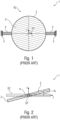
- Fig. 1 shows a micromechanical mirror device 1 according to the prior art in a schematic top view.
- the micromechanical mirror device 1 comprises a plate-shaped mirror 2 with a reflection surface 3 for reflecting light, which is rotatably fixed to a stationary support structure 5 by means of two springs 4.
- the plate-shaped mirror 2 is shown in its rest state RZ.
- Fig. 2 shows the micromechanical mirror device 1 according to the prior art in a schematic side view.
- the plate-shaped mirror 2 is deflected by a deflection AL from the rest state RZ.
- the plate-shaped mirror 2 and the closed frame structure 6 are shown in the rest state RZ.
- At least two connecting spring structures 9a of the connecting spring structures 9 are arranged in such a way and are designed to be elastically deformable in such a way that, in the resonant vibration state, they move back and forth about a torsion axis running transversely to the edge 7 of the plate-shaped mirror 2, as seen from the direction of the z-axis twist here.
- the two connecting spring structures 9a are arranged opposite each other on the x-axis and only perform the task of a torsion spring.
- At least two connecting spring structures 9b of the connecting spring structures 9 are arranged and designed to be elastically deformable in such a way that in the resonant vibration state there is a back and forth offset between the closed frame structure 6 and the plate-shaped mirror 2 on the respective connecting spring structure 9b The offset direction occurs parallel to the z-axis.
- the two connecting spring structures 9b are arranged opposite each other on the y-axis and only perform the task of a spiral spring.
- the spring arrangement comprises exactly two spring structures 8a, which are designed and arranged in such a way that the closed frame structure 6 and the plate-shaped mirror 2 can be rotatably deflected about the x-axis.
- the spring arrangement can include two spring structures 8a opposite each other on the x-axis, which are designed as torsion spring structures, so that the plate-shaped mirror 2 and the closed frame structure 6 can be brought into a rotational resonant oscillation state by means of electrical forces.
- connection arrangement comprises a first connection spring structure group, which contains a part of the connection spring structures 9, and a second connection spring structure group, which contains another part of the connection spring structures 9, wherein the connection spring structures 9a of the first connection spring structure group have a first elastic deformability, wherein the Connecting spring structures 9b of the second connecting spring structure group have a second elastic deformability, and wherein the first elastic deformability and the second elastic deformability differ.
- the first connecting spring structure group contains two connecting spring structures 9a of the connecting spring structures 9, which in the rest state RZ are arranged along the x-axis and are arranged mirror-symmetrically with respect to the yz plane.
- the second connecting spring structure group includes two connecting spring structures 9b of the connecting spring structures 9, which in the rest state RZ are arranged along the y-axis and are arranged mirror-symmetrically with respect to the yz plane.
- a distance AB between the closed frame structure 6 and the plate-shaped mirror 2 is constant along the edge 7 of the plate-shaped mirror 2, viewed from the direction of the z-axis, at least outside of areas of the connecting spring structures 9.
- the two connecting spring structures 9a can have the same elasticity.
- the two connecting spring structures 9b can have the same elasticity.
- an elliptical plate-shaped mirror 2 which can be deflected rotatably about the x-axis (or deflected translationally in the z-direction) is connected to the annular, closed frame structure 6 using two connecting spring structures 9a and two connecting spring structures 9b.
- the connecting spring structures 9a and 9b can have different geometric parameters or overall stiffnesses in a rotary design.
- the connecting spring structures 9b are arranged in the y-axis perpendicular to the axis of rotation.
- the connecting spring structures 9a lie in the x-axis or axis of rotation of the plate-shaped mirror 2.
- the total of four connecting spring structures 9 are designed here in a T-shape through the defined openings 10 in such a way that three bar spring sections 11a, 11b, 11c are created for each connecting spring structures 9, whereby two bar spring sections 11b, 11c are arranged parallel and one bar spring section is arranged perpendicular to the edge 7.
- the vertical bar spring section 11a is connected here to the plate-shaped mirror 2.
- the beam spring sections 11 have defined torsional and bending stiffnesses.
- the annular, closed frame structure 6 is connected to the support structure 5 designed as an anchor via the spring structures 8a located in the axis of rotation and the plate-shaped mirror 2 is thereby firmly mounted.
- Fig. 4 shows a second embodiment of a micromechanical mirror device 1 according to the invention in a schematic top view.
- the second exemplary embodiment is based on the first exemplary embodiment, so only the differences are explained below.
- At least two of the connecting spring structures 9 are each separated from the plate-shaped mirror 2 by a second opening 12 on their side facing the origin.
- At least two of the connecting spring structures 9 are H-shaped in such a way that they each have five bar spring sections 11, each with a first end region and a second end region, a first bar spring section 11a of the bar spring sections 11 runs transversely to the edge 7 of the plate-shaped mirror 2, the first end region of the first bar spring section 11a being connected to the first end regions of a second bar spring section 11b and a third bar spring section 11c of the bar spring sections 11, which each run along the edge 7 of the plate-shaped mirror 2 and each are connected at the second end region to the closed frame structure 6, and wherein the second end region of the first beam spring section 11a is connected to the first end regions of a fourth beam spring section 11d and a fifth beam spring section 11e of the beam spring sections 11, which run along the edge 7 of the plate-shaped mirror 2 and are each connected to the plate-shaped mirror 2 at the second end region.
- the second bar spring section 11b and the third bar spring section 11c are the H-shaped connecting spring structures 9, which each run along the edge 7 of the plate-shaped mirror 2 and each at the second end region are connected to the closed frame structure 6, separated from the closed frame structure 6 on their side facing away from the origin by a first opening 10.
- the fourth bar spring section 11d and the fifth bar spring section 11e of the H-shaped connecting spring structures 9, which each run along the edge 7 of the plate-shaped mirror 2 and are each connected to the plate-shaped mirror 2 at the second end region, are at their point facing the origin Each side is separated from the plate-shaped mirror 2 by a second opening 12.
- an elliptical plate-shaped mirror 2 which can be deflected rotationally about the x-axis (or translationally in the z-direction), is connected to the annular, closed frame structure 6 using two connecting spring structures 9a and two connecting spring structures 9b.
- the connecting spring structures 9a and 9b can have different geometric parameters or overall stiffnesses in a rotary design.
- the connecting spring structures 9b are arranged in the y-axis perpendicular to the axis of rotation.
- the connecting spring structures 9a lie in the x-axis or axis of rotation of the plate-shaped mirror 2.
- the total of four connecting spring structures 9 are thereby designed with the defined openings 10 and 12 in such a way that five bar spring sections 11a, 11b, 11c, 11d, 11e per connecting spring structure 9 arise, with four beam spring sections 11b, 11c, 11d, 11e being arranged parallel and a connecting beam spring section 11a perpendicular to the edge 7.
- the beam spring sections 11 have defined torsional and bending stiffnesses.
- the annular, closed frame structure 6 is connected to the support structure 5 designed as an anchor via the spring structures 8a located in the axis of rotation and the plate-shaped mirror 2 is thereby firmly mounted.
- Fig. 5 shows a third exemplary embodiment of a micromechanical mirror device 1 not according to the invention in a schematic top view.
- the third exemplary embodiment is based on the first exemplary embodiment, so only the differences are explained below.
- the connecting spring structures 9a of the connecting spring structures 9 are arranged in such a way and are designed to be elastically deformable in such a way that in the resonant vibration state they twist back and forth about a torsion axis running transversely to the edge 7 of the plate-shaped mirror 2 as seen from the direction of the z-axis.
- the two connecting spring structures 9a are arranged opposite each other on the x-axis and only perform the task of a torsion spring.
- the second connecting spring structure group contains four connecting spring structures 9d of the connecting spring structures 9, which in the rest state RZ are arranged adjacent to the y-axis and are arranged mirror-symmetrically with respect to the xz plane and the yz plane.
- the four connecting spring structures 9d can have the same elasticity.
- the connecting spring structures 9d of the connecting spring structures 9 are arranged in such a way and designed to be elastically deformable in such a way that on the respective connecting spring structure 9b in the resonant vibration state there is a back and forth offset between the closed frame structure 6 and the plate-shaped mirror 2 in a direction parallel to the z-axis Offset direction occurs, and that in the resonant vibration state they twist back and forth about a torsion axis running transversely to the edge 7 of the plate-shaped mirror 2, as seen from the direction of the z-axis.
- the four connecting spring structures 9d are adjacent arranged to the y-axis and perform both the task of a bending spring and the task of a torsion spring.
- a plate-shaped mirror 2 which can be deflected rotationally about the x-axis (or translationally in the z-direction), is connected to the annular, closed frame structure 6 using four connecting spring structures 9d and two connecting spring structures 9a.
- the connecting spring structures 9d and 9a can have different geometric parameters or stiffnesses.
- the connecting spring structures 9d and 9a are arranged symmetrically with respect to both axes.
- the connecting spring structures 9a lie in the x-axis or axis of rotation of the plate-shaped mirror 2.
- the total of six connecting spring structures 9 are designed here in a T-shape through the openings 10 in such a way that three bar spring sections 11a, 11b, 11c are created per connecting spring structure 9, with two Bar spring sections 11b, 11c are each arranged parallel and a bar spring section 11a is arranged perpendicular to the edge 7.
- the vertical bar spring section 11a is connected here to the plate-shaped mirror 2.
- the beam spring sections 11 have defined torsional and bending stiffnesses and can be both rectilinear and curved in shape, for example parallel to the shape of the outer edge 7 of the plate-shaped mirror 2.
- the annular, closed frame structure 6 is connected to the support structure 5 designed as an anchor via the spring structures 8a located in the axis of rotation and the plate-shaped mirror 2 is thereby firmly mounted.
- Fig. 6 shows a fourth exemplary embodiment of a micromechanical mirror device 1 not according to the invention in a schematic top view.
- the fourth exemplary embodiment is based on the first exemplary embodiment, so only the differences are explained below.
- the second connection spring structure group includes two connection spring structures 9b of the connection spring structures 9, which are in the rest state RZ are arranged along the y-axis and are arranged mirror-symmetrically with respect to the yz-plane.
- the connecting spring structures 9b of the connecting spring structures 9 are arranged in such a way and designed to be elastically deformable in such a way that on the respective connecting spring structure 9b in the resonant vibration state there is a back and forth offset between the closed frame structure 6 and the plate-shaped mirror 2 in a direction parallel to the z-axis Offset direction occurs.
- the two connecting spring structures 9b are arranged opposite each other on the y-axis and only perform the task of a spiral spring.
- the first connecting spring structure group contains four connecting spring structures 9c of the connecting spring structures 9, which in the rest state RZ are arranged adjacent to the x-axis and are arranged mirror-symmetrically with respect to the xz plane and the yz plane.
- the four connecting spring structures 9c can have the same elasticity.
- the connecting spring structures 9c of the connecting spring structures 9 are arranged in such a way and designed to be elastically deformable in such a way that in the resonant vibration state there is a back and forth offset between the closed frame structure 6 and the plate-shaped mirror 2 in a direction parallel to the z-axis on the respective connecting spring structure 9c Offset direction occurs, and that in the resonant vibration state they twist back and forth about a torsion axis running transversely to the edge 7 of the plate-shaped mirror 2, as seen from the direction of the z-axis.
- the four connecting spring structures 9c are arranged adjacent to the y-axis and perform both the task of a spiral spring and the task of a torsion spring.
- FIG. 6 A plate-shaped mirror 2 that can be rotated around the x-axis is connected to the annular, closed frame structure 6 using two connecting spring structures 9b and four connecting spring structures 9c.
- the connecting spring structures 9b and 9c can have different geometric parameters or overall stiffness.
- the connecting spring structures 9b and 9c are arranged symmetrically with respect to both axes.
- the connecting spring structures 9b lie in the y-axis (perpendicular to the axis of rotation) of the plate-shaped mirror 2.
- the total of six connecting spring structures 9 are designed here in a T-shape through the defined openings 10 in such a way that three bar spring sections 11a, 11b, 11c are created per connecting spring structure 9 , wherein two beam spring sections 11b, 11c are arranged parallel and one beam spring section 11a is arranged perpendicular to edge 7.
- the vertical bar spring section 11a is connected here to the plate-shaped mirror 2.
- the beam spring sections 11 have defined torsional and bending stiffnesses.
- the annular, closed frame structure 6 is connected to the support structure 5 designed as an anchor via the spring structures 8a located in the axis of rotation and the plate-shaped mirror 2 is thereby firmly mounted.
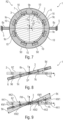
- Fig. 7 shows a fifth exemplary embodiment of a micromechanical mirror device 1 not according to the invention in a schematic top view.
- the fifth exemplary embodiment is based on the third and fourth exemplary embodiments, so only the differences are explained below.
- the first connecting spring structure group includes four connecting spring structures 9c of the connecting spring structures 9, which are designed as described above.
- the second connecting spring structure group comprises four connecting spring structures 9d of the connecting spring structures 9, which are also designed as described above.
- a plate-shaped mirror 2 which can be deflected rotationally about the x-axis (or translationally in the z-direction), is connected to the annular, closed frame structure 6 using four connecting spring structures 9c and four connecting spring structures 9d.
- the connecting spring structures 9c and 9d can have different geometric parameters or overall stiffness.
- the connecting spring structures 9c and 9d are arranged symmetrically with respect to both axes, with the connecting spring structures 9d being closer to the y-axis and the connecting spring structures 9c being closer to the x-axis.
- the total of eight connecting spring structures 9 are designed in a T-shape through the defined openings 10 in such a way that three bar spring sections 11a, 11b, 11c are created per connecting spring structure 9, with two bar spring sections 11b, 11c being arranged parallel and one bar spring section 11a perpendicular to the edge 7.
- the vertical bar spring section 11a is connected here to the plate-shaped mirror 2.
- the beam spring sections 11 have defined torsional and bending stiffnesses.
- the annular, closed frame structure 6 is connected to the support structure 5 designed as an anchor via the spring structures 8a located in the axis of rotation and the plate-shaped mirror 2 is thereby firmly mounted.
- Fig. 8 shows the fifth exemplary embodiment of the micromechanical mirror device 1 not according to the invention in a schematic side view.
- the plate-shaped mirror 2 and the closed frame are deflected from the rest state RZ by a rotational deflection AL.
- Fig. 9 shows a representation of the coupling forces KK, inertia forces TK, spring moments FM and coupling moments KM acting on the fifth exemplary embodiment in a schematic side view.
- the spring moment FM is shown, which is exerted on the closed frame structure 6 by a spring structure 8a and is opposite to the deflection.
- the coupling forces KK1 and the coupling moments KM1 are shown, which are caused by the spring moments FM from the closed frame structure 6 by means of which the connecting spring structures 9d are transferred to the plate-shaped mirror 2 and are therefore also opposed to the deflection.
- the coupling forces KK2 and the coupling forces KM2 are also shown, which are caused by the spring moments FM and are transmitted from the closed frame structure 6 to the plate-shaped mirror 2 by means of the connecting spring structures 9c and are opposite to the deflection AL. Furthermore, the inertia forces TK caused by the accelerated movement of the plate-shaped mirror 2 and distributed over the entire plate-shaped mirror 2 are shown, which always act in the direction of the deflection AL. The magnitude of these inertial forces TK depends on the distance to the rotation axis x of the plate-shaped mirror 2 and is generally maximum at the outermost edge and on the rotation axis 0.
- the dynamic deformation of the closed frame structure 6 that also occurs can be neglected in comparison to the superimposed deformation caused by the spring structure 8a.
- the deformation of the closed frame structure 6 caused by the spring structures 8a in turn leads to undesirable coupling moments KM1 and KM2, which, however, are due to the elasticity Torsion of the connecting spring structures 9c and 9d has a significantly smaller effect on the deformation of the plate-shaped mirror plate 2.
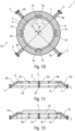
- Fig. 10 shows a sixth exemplary embodiment of a micromechanical mirror device 1 not according to the invention in a schematic top view.
- the fifth exemplary embodiment is based on the previous exemplary embodiments, so only the differences are explained below.
- the spring arrangement comprises at least two spring structures 8b, which are designed and arranged such that the closed frame structure 6 and the plate-shaped mirror 2 can be deflected translationally in the direction of the z-axis.
- connection arrangement comprises at least four connection spring structures 9e, which have the same elastic deformability.
- a number of spring structures 8 corresponds to a number of connecting spring structures 9, with the spring structures 8 and the connecting spring structures 9 being arranged alternately along the edge 7.
- FIG. 10 An elliptical plate-shaped mirror 2, which can be deflected translationally in the z direction, is connected to the annular, closed frame structure 6 using four connecting spring structures 9e.
- the connecting spring structures 9e have the same geometric parameters or overall stiffness.
- the connecting spring structures 9e are arranged at equal distances from one another and rotated by 45° with respect to the main axis.
- the total of four connecting spring structures 9 are designed here through the defined openings 10 in a T-shape such that three bar spring sections 11a, 11b, 11c are created per connecting spring structure 9, with two 11b, 11c arranged parallel and one bar spring section 11a perpendicular to the edge 7 are.
- the vertical bar spring section 11a is connected here to the plate-shaped mirror 2.
- the beam spring sections 11 have defined torsional and bending stiffnesses.
- the annular, closed frame structure 6 is connected to the support structure 5 designed as an anchor via four spring structures 8b arranged at equal distances from one another and at equal distances from the connecting spring structures 9e, and the plate-shaped mirror 2 is thereby firmly mounted.
- the four spring structures 8b are arranged in the main axes.
- Fig. 11 shows the sixth exemplary embodiment of a micromechanical mirror device 1 not according to the invention in a schematic side view.
- the plate-shaped mirror 2 and the closed frame are deflected from the rest state RZ by a translational deflection AL.
- Fig. 12 shows a representation of the forces acting on the sixth exemplary embodiment in a schematic side view. Shown are the spring forces FK, which are exerted by the spring structures 8b on the closed frame structure 6 and are opposite to the deflection AL. In addition, the coupling forces KK are shown, which are caused by the spring forces and are transmitted via the closed frame structure 6 through the connecting spring structures 9e to the plate-shaped mirror 2 and are also opposite to the deflection AL. Furthermore, the inertial forces TK caused by the accelerated movement of the plate-shaped mirror 2 and distributed evenly over the entire plate-shaped mirror 2 are shown, which act in the direction of the deflection AL.
- the coupling forces KK transmitted via the connecting spring structures 9 to the plate-shaped mirror 2 counteract the inertial forces TK acting on the plate-shaped mirror 2, whereby the dynamic deformation of the plate-shaped mirror 2 is reduced if the coupling forces KK are set in the size range of the inertial forces.
- This can be achieved by deliberately decoupling the plate-shaped mirror 2 from the spring structures 8b the adjustment of the stiffness of the connecting spring structures 9 between the closed frame structure 6 and the plate-shaped mirror 2 by selecting the geometry parameters on the one hand and an adapted position of the connecting spring structures in the xy plane along the edge 7 on the other hand.
- the coupling moments KM include components which are caused by a dynamic deformation of the closed frame structure 6. These proportions are at least partially compensated for by the elasticity of the connecting spring structures 9e. The coupling moments KM are therefore significantly smaller due to the elasticity of the connecting spring structures 9e than would be the case with a rigid coupling of the plate-shaped mirror 2 to the closed frame structure 6, so that the dynamic deformation of the plate-shaped mirror 2 is reduced.
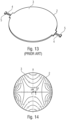
- Fig. 13 shows a perspective view of the micromechanical mirror device 1 in the rest position according to the prior art Fig. 1 with an aperture of 3.5 mm and a resonance frequency of 4000 Hz.
- Fig. 14 shows an example of a representation of the dynamic deformation using contour lines of a plate-shaped mirror 2 of a micromechanical mirror device 1 according to the prior art Fig. 13 with a deflection AL around the x-axis of 1°.
- the root mean square of the dynamic deformation is 82 nm.
- the maximum amplitude from peak to peak of the dynamic deformation is 366 nm.
- the dynamic deformation of the plate-shaped mirror plate 2 in the area of the spring structures 4, which is opposite to the deflection AL can be clearly seen Fig.13 in the area of the intersection of edge 7 and the x-axis.
- the values of the dynamic deformation in the first quadrant are in the negative range.
- values of the dynamic deformations which are mainly caused by inertia, lie in the area of the intersection points of edge 7 and y-axis (in the first quadrant) in the positive area, i.e. in the direction of the deflection.
- Fig. 15 shows a perspective view of the third exemplary embodiment of a micromechanical mirror device 1 not according to the invention Fig. 5 .
- the plate-shaped mirror 2 corresponds to the plate-shaped mirror 2 in terms of its thickness, its material and its diameter Figure 13 , with the same resonance frequency of the plate-shaped mirror 2.
- Fig. 16 shows a representation of the optimized course of the dynamic deformation using contour lines of the third exemplary embodiment of a micromechanical mirror device 1 according to the invention Fig. 15 .
- the deflection AL is also 1°.
- the root mean square of the dynamic deformation is now only 9 nm and the maximum amplitude from peak to peak of the dynamic deformation is only 38.6 nm.
- the dynamic deformation coupled in by the spring structure along the edge 7, which is opposite to the deflection Al, can be clearly seen is, ie negative values in the first quadrant.
- the area between the x-axis and the intersection of the mirror plate edge and y-axis shows a dynamic deformation in the direction of the deflection AL, i.e. positive values in the first quadrant.
- Fig. 17 shows a diagram showing the dynamic deformation of the micromechanical mirror device 1 according to the prior art Fig. 13 along a section A along the y-axis.
- the maximum dynamic deformations occur at the edge 7 of the plate-shaped mirror 2 on both sides of the center of gravity SP and amount to -183 nm on one side and + 183 nm on the other side.
- Fig. 18 shows a diagram to illustrate the compensation of the two deformation components of the dynamic deformation to illustrate the dynamic Deformation of the third exemplary embodiment of the micromechanical mirror device 1 not according to the invention Fig. 15 along a section B along the y-axis.
- the maximum dynamic deformations occur between the center of gravity SP and the edge 7 of the plate-shaped mirror 2 on both sides of the center of gravity SP and amount to -19.3 nm on one side and +19.3 nm on the other side.
- Fig. 19 a common diagram for illustrating the dynamic deformation along a section A of the micromechanical mirror device 1 according to the prior art and for illustrating the dynamic deformation along a section B of the third exemplary embodiment of a micromechanical mirror device 1 not according to the invention.
- Fig. 19 shows the curves of the 17 and 18 on the same scale. A significant reduction in dynamic deformation by almost an order of magnitude can be clearly seen.
Landscapes
- Physics & Mathematics (AREA)
- General Physics & Mathematics (AREA)
- Optics & Photonics (AREA)
- Engineering & Computer Science (AREA)
- Mechanical Engineering (AREA)
- Computer Hardware Design (AREA)
- Microelectronics & Electronic Packaging (AREA)
- Micromachines (AREA)
- Mechanical Optical Scanning Systems (AREA)
Description
- Die Erfindung betrifft eine mikromechanische Spiegelvorrichtung, welche einen plattenförmigen Spiegel mit einer Reflexionsfläche zum Reflektieren von Licht umfasst, welcher mittels elektrischer Kräfte in einen resonanten Schwingungszustand bringbar ist, so dass einfallendes Licht in Abhängigkeit von der jeweiligen hin und her gehenden Auslenkung des plattenförmigen Spiegels reflektiert werden kann. Derartige mikromechanische Spiegelvorrichtungen werden auch MEMS-Scannerspiegel genannt.
- Mikromechanische Spiegelvorrichtungen der hier beschriebenen Art werden häufig in optischen Anwendungen mit Ablenkeinheiten für Lichtstrahlen verwendet, bei denen Auslenkungen mit vergleichsweise großen Frequenzen und/oder großen Aperturen bzw. Reflexionsflächen gefordert sind. Problematisch ist hier, dass es bei der üblichen Dimensionierung der plattenförmigen Spiegel im Betrieb zu Verformungen bzw. Deformationen der plattenförmigen Spiegel kommt, die je nach gewählter Frequenz, Apertur und Auslenkung vom Nanometer- bis zum Mikrometerbereich reichen können. Diese Deformationen führen dann wiederum zu einer unerwünschten Beeinflussung des Reflexionsverhaltens der jeweiligen plattenförmigen Spiegel. Dabei können die Deformationen der plattenförmigen Spiegel im Betrieb einen anwendungsspezifischen Wert überschreiten, wodurch der Anwendungsbereich entweder eingeschränkt wird oder die Anwendung an sich nicht mehr möglich ist.
- Die Dokumente [1] bis [11] beschreiben jeweils unterschiedliche vorbekannte mikromechanische Spiegelvorrichtungen.
- Die Aufgabe der vorliegenden Erfindung besteht darin, eine verbesserte mikromechanische Spiegelvorrichtung bereitzustellen.
- Die Aufgabe wird gelöst durch eine mikromechanische Spiegelvorrichtung gemäß Anspruch 1.
- Der Begriff "plattenförmig" bezieht sich dabei auf die grundsätzliche Form des Spiegels, welche derart ist, dass der Spiegel im Vergleich zu einer Länge und einer Breite eine wesentlich geringere Dicke aufweist. Der Spiegel bzw. seine Reflexionsfläche kann dabei elliptisch, insbesondere rund, oder mehreckig, insbesondere rechteckig oder quadratisch ausgebildet sein. Die Reflexionsfläche kann derart an die Art des einfallenden Lichts angepasst sein, so dass ein hoher Reflexionsgrad erreicht wird. Das Licht kann prinzipiell von jeder Lichtquelle stammen, insbesondere jedoch von einem Laser. Der Ruhezustand ist derjenige Zustand, den die mikromechanische Spiegelvorrichtung einnimmt, wenn der plattenförmige Spiegel und die geschlossene Rahmenstruktur nicht durch elektrische Kräfte ausgelenkt sind.
- Der Begriff "geschlossen" bezieht sich hierbei auf die grundsätzliche Form der Rahmenstruktur, welche derart ist, dass sie nach Art eines Ringes ausgebildet ist, so dass Kräfte, welche an einem beliebigen Punkt in den Rahmen eingeleitet werden, sich zu beiden Seiten längs des Rings verteilen können. Dabei bezieht sich der Begriff "vollständig umrahmt" darauf, dass die Rahmenstruktur den Spiegel ohne Unterbrechung vollständig umringt.
- Die Federstrukturen sind so ausgebildet, dass sie die geschlossene Rahmenstruktur und den daran angeordneten Spiegel bei einer Auslenkung aus ihrer Ruhelage mittels Federkräften zurück in ihre Ruhelage drängen. Die ortsfeste Tragstruktur kann mehrere Abschnitte aufweisen, wobei jede der Federstrukturen an wenigstens einem der Abschnitte der Tragstruktur befestigt ist.
- Die Anregung des resonanten Schwingungszustandes kann mit bekannten elektrischen Antrieben erfolgen, welche elektrostatische, elektromagnetische oder piezoelektrische Kräfte erzeugen, welche auf den geschlossenen Rahmen und/oder auf den plattenförmigen Spiegel periodisch wirken.
- Die Verbindungsfederstrukturen stellen die Verbindung zwischen dem plattenförmigen Spiegel und der geschlossenen Rahmenstruktur her. Die Verbindung erfolgt derart elastisch, dass sich die Verbindungsfederstrukturen im resonanten Schwingungszustand periodisch verformen, so dass der plattenförmige Spiegel von der geschlossenen Rahmenstruktur teilweise mechanisch entkoppelt ist. Letzteres bedeutet, dass eine relative Bewegung eines an eine der Verbindungsstrukturen angrenzenden Bereichs des Spiegels gegenüber eines an die jeweilige Verbindungsstruktur angrenzenden Bereichs der Rahmenstruktur möglich ist, sofern sich die Spiegelvorrichtung im resonanten Schwingungszustand befindet. Insbesondere können die die Verbindungsfederstrukturen derart elastisch verformbar ausgebildet und angeordnet sein, dass der plattenförmige Spiegel von einer in dem resonanten Schwingungszustand auftretenden dynamischen Verformung der geschlossenen Rahmenstruktur zumindest teilweise entkoppelt ist.
- Der plattenförmige Spiegel, die geschlossene Rahmenstruktur, die Federanordnung und die Verbindungsanordnung können jeweils oder insgesamt einstückig ausgebildet sein. Der plattenförmige Spiegel, die geschlossene Rahmenstruktur, die Federanordnung und die Verbindungsanordnung können aber auch jeweils oder insgesamt dadurch hergestellt werden, dass mehrere Einzelteile gefertigt werden, welche dann, beispielsweise stoffschlüssig, zusammengefügt werden. Die Erstreckungen in z-Richtung, also die Höhen, des plattenförmigen Spiegels, der geschlossenen Rahmenstruktur der Federanordnung und der Verbindungsanordnung können auf der Ebene der genannten Bauteile oder auf der Ebene der Gesamtheit der genannten Bauteile einheitlich oder unterschiedlich sein.
- Die Deformation eines endlich steifen plattenförmigen Spiegels im resonanten Schwingungszustand wird als dynamische Deformation bezeichnet und ist im Umkehrpunkt der Schwingung am größten. Sie setzt sich allgemein aus einer "federabhängigen" Deformation, welche durch eine Einwirkung von Federkräften und/oder Federmomenten der Federanordnung auf den plattenförmigen Spiegel hervorgerufen wird, und einer "plattenabhängigen" Deformation, welche durch Trägheitskräfte und/oder Trägheitsmomente hervorgerufen wird, zusammen.
- Die "federabhängige" Deformation kann insbesondere bei hohen Resonanzfrequenzen und großen Spiegeln nicht vernachlässigt werden, da bei steigender Resonanzfrequenz und steigender Größe des Spiegels die notwendige Steifigkeit der Federanordnung steigt und die erreichbare Steifigkeit des plattenförmigen Spiegels gleichzeitig abnimmt.
- Die erfindungsgemäße Kombination mit der geschlossenen Rahmenstruktur, mit der Federanordnung mit den mindestens zwei Federstrukturen und mit der Verbindungsanordnung mit mindestens vier Verbindungsfederstrukturen bewirkt nun, dass die Federkräfte und/oder Federmomente der Federanordnung nicht unmittelbar auf den plattenförmigen Spiegel wirken. Vielmehr werden die Federkräfte und/oder Federmomente der Federanordnung zunächst auf die geschlossene Rahmenstruktur übertragen. Von dort werden sie als Koppelkräfte und/oder Koppelmomente verteilt über wenigstens vier Verbindungsfederstrukturen auf dem plattenförmigen Spiegel übertragen wobei der plattenförmige Spiegel durch die Elastizität der Verbindungsfederstrukturen von der geschlossenen Rahmenstruktur teilweise mechanisch entkoppelt ist.
- Praktische Versuche und Modellrechnungen haben nun gezeigt, dass die maximale dynamische Deformation des plattenförmigen Spiegels der erfindungsgemäßen mikromechanischen Spiegelvorrichtung deutlich geringer ist, als bei herkömmlichen mikromechanischen Spiegelvorrichtungen, bei denen die Federkräfte und/oder Federmomente der Federanordnung direkt, also ohne Zwischenschaltung einer Rahmenstruktur, auf dem plattenförmigen Spiegel wirken. Weitere praktische Versuche und Modellrechnungen haben gezeigt, dass die maximale dynamische Deformation des plattenförmigen Spiegels der erfindungsgemäßen mikromechanischen Spiegelvorrichtung ebenfalls deutlich geringer ist, als bei mikromechanischen Spiegelvorrichtungen, welche einen offene Rahmenstruktur aufweisen. Weitere praktische Versuche und Modellrechnungen haben gezeigt, dass die maximale dynamische Deformation des plattenförmigen Spiegels der erfindungsgemäßen mikromechanischen Spiegelvorrichtung deutlich geringer ist, als bei mikromechanischen Spiegelvorrichtungen, welche eine starre, also nicht elastische, Verbindung zwischen dem plattenförmigen Spiegel und der Rahmenstruktur aufweisen. Letzteres dürfte darauf beruhen, dass durch die Elastizität der Verbindungsfederstrukturen verhindert wird, dass eine dynamische Verformung der Rahmenstruktur, welche aufgrund der endlichen Steifheit der Rahmenstruktur nie ganz ausgeschlossen werden kann, zu einer dynamischen Verformung des plattenförmigen Spiegels beiträgt.
- Insgesamt bewirkt die Erfindung, dass - bei gegebener Reflexionsfläche des Spiegels und bei gegebener Resonanzfrequenz - die maximale dynamische Deformation des plattenförmigen Spiegels im Vergleich zu anderen Lösungen verringert wird, da die erfindungsgemäße Merkmalskombination bewirkt, dass sich die "plattenabhängige" Deformation und die "federabhängige" Deformation zumindest teilweise kompensieren. Umgekehrt bewirkt die Erfindung, dass - bei gegebener Deformation - die Reflexionsfläche und/oder die Resonanzfrequenz erhöht werden kann.
- Gemäß einer vorteilhaften Weiterbildung der Erfindung sind wenigstens zwei Verbindungsfederstrukturen der Verbindungsfederstrukturen derart angeordnet und derart elastisch verformbar ausgebildet, dass sie in dem resonanten Schwingungszustand um eine aus Richtung der z-Achse gesehen quer zu dem Rand des plattenförmigen Spiegels verlaufende Torsionsachse hin und her tordieren. Auf diese Weise kann die Übertragung von Koppelmomenten von der geschlossenen Rahmenstruktur auf den plattenförmigen Spiegel verhindert oder wenigstens verringert werden, welche durch eine dynamische Verformung der geschlossenen Rahmenstruktur erzeugt werden, so dass die dynamische Verformung des plattenförmigen Spiegels im resonanten Schwingungszustand verringert werden kann. In diesem Ausführungsbeispiel übernimmt die jeweilige Verbindungsfederstruktur die Aufgabe einer Torsionsfeder.
- Nach einer vorteilhaften Weiterbildung der Erfindung sind wenigstens zwei Verbindungsfederstrukturen der Verbindungsfederstrukturen derart angeordnet und derart elastisch verformbar ausgebildet, dass an der jeweiligen Verbindungsfederstruktur in dem resonanten Schwingungszustand ein hin und her gehender Versatz zwischen der geschlossenen Rahmenstruktur und dem plattenförmigen Spiegel in einer parallel zu der z-Achse verlaufenden Versatzrichtung auftritt. Auf diese Weise kann die Übertragung von Koppelkräften von der geschlossenen Rahmenstruktur auf den plattenförmigen Spiegel verhindert oder wenigstens verringert werden, welche durch eine dynamische Verformung der geschlossenen Rahmenstruktur erzeugt werden, so dass die dynamische Verformung des plattenförmigen Spiegels im resonanten Schwingungszustand verringert werden kann. In diesem Ausführungsbeispiel übernimmt die jeweilige Verbindungsfederstruktur die Aufgabe einer Biegefeder.
- Selbstverständlich können die wenigstens zwei Verbindungsfederstrukturen auch so ausgebildet sein, dass sie im resonanten Schwingungszustand gleichzeitig hin und her tordieren und einen hin und her gehenden Versatz ermöglichen. In diesem Ausführungsbeispiel übernimmt die jeweilige Verbindungsfederstruktur sowohl die Aufgabe einer Biegefeder als auch die Aufgabe einer Torsionsfeder.
- Gemäß der Erfindung sind, aus der Richtung der z-Achse gesehen, mindestens zwei der Verbindungsfederstrukturen derart H-förmig ausgebildet, dass sie jeweils fünf Balkenfederabschnitte mit jeweils einem ersten Endbereich und einem zweiten Endbereich aufweisen, wobei ein erster Balkenfederabschnitt der Balkenfederabschnitte quer zum Rand des plattenförmigen Spiegels verläuft, wobei der erste Endbereich des ersten Balkenfederabschnittes mit den ersten Endbereichen eines zweiten Balkenfederabschnittes und eines dritten Balkenfederabschnittes der Balkenfederabschnitte verbunden ist, welche jeweils entlang des Randes des plattenförmigen Spiegels verlaufen und jeweils an dem zweiten Endbereich mit der geschlossenen Rahmenstruktur verbunden sind, und wobei der zweite Endbereich des ersten Balkenfederabschnittes mit den ersten Endbereichen eines vierten Balkenfederabschnittes und eines fünften Balkenfederabschnittes der Balkenfederabschnitte verbunden ist, welche entlang des Randes des plattenförmigen Spiegels verlaufen und jeweils an dem zweiten Endbereich mit dem plattenförmigen Spiegel verbunden sind.
- Gemäß der Erfindung sind der zweite Balkenfederabschnitt und der dritte Balkenfederabschnitt der H-förmigen Verbindungsfederstrukturen, welche jeweils entlang des Randes des plattenförmigen Spiegels verlaufen und jeweils an dem zweiten Endbereich mit der geschlossenen Rahmenstruktur verbunden sind, an ihrer dem Ursprung abgewandten Seite jeweils durch eine erste Öffnung von der geschlossenen Rahmenstruktur getrennt.
- Gemäß der Erfindung sind der vierte Balkenfederabschnitt und der fünfte Balkenfederabschnitt der H-förmigen Verbindungsfederstrukturen, welche jeweils entlang des Randes des plattenförmigen Spiegels verlaufen und jeweils an dem zweiten Endbereich mit dem plattenförmigen Spiegel verbunden sind, an ihrer dem Ursprung zugewandten Seite jeweils durch eine Öffnung von dem plattenförmigen Spiegel getrennt.
- Derartige H-förmige Verbindungsfederstrukturen können sowohl die Aufgabe einer Biegefeder als auch die Aufgabe einer Torsionsfeder übernehmen. Dabei hat sich gezeigt, dass sich derartige Verbindungsfederstrukturen günstig auf die dynamische Verformung des plattenförmigen Spiegels auswirken.
- Gemäß einer vorteilhaften Weiterbildung der Erfindung umfasst die Federanordnung genau zwei Federstrukturen, welche so ausgebildet und angeordnet sind, dass die geschlossene Rahmenstruktur und der plattenförmige Spiegel rotatorisch um die x-Achse auslenkbar sind. Ein derart gelagerter plattenförmiger Spiegel wird auch als Kippspiegel bezeichnet. Rotatorische gelagerte Spiegel können beispielsweise in Projektionsdisplays, z.B. Retina Scanning Displays, in Lesegeräten für Muster und Bilder, z.B. Barcode-Lesegeräte, in Messgeräten, in Laserdruckern oder in Direkt-Belichtern eingesetzt werden.
- Gemäß einer Weiterbildung der Erfindung umfasst die Verbindungsanordnung eine erste Verbindungsfederstrukturgruppe, welche einen Teil der Verbindungsfederstrukturen beinhaltet, und eine zweite Verbindungsfederstrukturgruppe, welche einen anderen Teil der Verbindungsfederstrukturen beinhaltet, wobei die Verbindungsfederstrukturen der ersten Verbindungsfederstrukturgruppe eine erste elastische Verformbarkeit aufweisen, wobei die Verbindungsfederstrukturen der zweiten Verbindungsfederstrukturgruppe eine zweite elastische Verformbarkeit aufweisen, und wobei sich die erste elastische Verformbarkeit und die zweite elastische Verformbarkeit unterscheiden. Eine derartige Bauform ist insbesondere bei rotatorisch gelagerten Spiegeln von Vorteil. In diesem Fall kann die erste Verbindungsfederstrukturgruppe in Bezug auf jene Kräfte und Momente optimiert werden, welche an oder benachbart zu der Rotationsachse zu übertragen sind, während die zweite Verbindungsfederstrukturgruppe in Bezug auf jene Kräfte und Momente optimiert werden kann, welche entfernt von der Rotationsachse zu übertragen sind. Auf diese Weise kann die dynamische Verformung des plattenförmigen Spiegels weiter verringert werden.
- Gemäß einer zweckmäßigen Weiterbildung der Erfindung beinhaltet die erste Verbindungsfederstrukturgruppe zwei Verbindungsfederstrukturen der Verbindungsfederstrukturen, welche in dem Ruhezustand längs der x-Achse angeordnet und bezüglich der yz-Ebene spiegelsymmetrisch angeordnet sind.
- Gemäß einer zweckmäßigen Weiterbildung der Erfindung beinhaltet die erste Verbindungsfederstrukturgruppe vier Verbindungsfederstrukturen der Verbindungsfederstrukturen, welche in dem Ruhezustand benachbart zu der der x-Achse angeordnet sind und bezüglich der xz-Ebene und der yz-Ebene spiegelsymmetrisch angeordnet sind.
- Gemäß einer zweckmäßigen Weiterbildung der Erfindung beinhaltet die zweite Verbindungsfederstrukturgruppe zwei Verbindungsfederstrukturen der Verbindungsfederstrukturen, welche in dem Ruhezustand längs der y-Achse angeordnet und bezüglich der yz-Ebene spiegelsymmetrisch angeordnet sind.
- Gemäß einer zweckmäßigen Weiterbildung der Erfindung beinhaltet die zweite Verbindungsfederstrukturgruppe vier Verbindungsfederstrukturen der Verbindungsfederstrukturen, welche in dem Ruhezustand benachbart zu der y-Achse angeordnet sind und bezüglich der xz-Ebene und der yz-Ebene spiegelsymmetrisch angeordnet sind.
- Insgesamt hat sich gezeigt, dass Ausführungsbeispiele mit einer ersten Verbindungsfederstrukturgruppe und mit einer zweiten Verbindungsfederstrukturgruppe zu einer geringen dynamischen Verformung des plattenförmigen Spiegels führen.
- Gemäß einer bevorzugten Weiterbildung der Erfindung umfasst die Federanordnung wenigstens zwei Federstrukturen, welche so ausgebildet und angeordnet sind, dass die geschlossene Rahmenstruktur und der plattenförmige Spiegel translatorisch in der Richtung der z-Achse auslenkbar sind. Ein derart gelagerter Spiegel wird auch als Pumpspiegel bezeichnet. Pumpspiegel kommen zum Beispiel im Bereich der Spektroskopie als Fourier-Transform-Spektrometer zum Einsatz.
- Gemäß einer bevorzugten Weiterbildung der Erfindung umfasst die Verbindungsanordnung wenigstens vier Verbindungsfederstrukturen, welche eine selbe elastische Verformbarkeit aufweisen. Auf diese Weise kann ein translatorisch hin und her gehender Spiegels sicher gelagert werden, so dass die dynamische Formung des plattenförmigen Spiegels günstig beeinflusst wird. Gemäß einer zweckmäßigen Weiterbildung der Erfindung eine Anzahl der Federstrukturen einer Anzahl von Verbindungsfederstrukturen entspricht, wobei die Federstrukturen und die Verbindungsfederstrukturen längs des Randes abwechselnd angeordnet sind. Auf diese Weise kann die dynamische Verformung des plattenförmigen Spiegels weiter verringert werden. Nach einer zweckmäßigen Weiterbildung der Erfindung ist längs des Randes des plattenförmigen Spiegels aus Richtung der z-Achse gesehen ein Abstand zwischen der geschlossenen Rahmenstruktur und dem plattenförmigen Spiegel zumindest außerhalb von Bereichen der Verbindungsfederstrukturen gleichbleibend. Auf diese Weise kann eine besonders kompakte Bauweise realisiert werden. Zudem wirkt sich eine derartige Bauform günstig auf die dynamische Verformung des plattenförmigen Spiegels aus.
- Im Folgenden werden die vorliegende Erfindung und deren Vorteile anhand von Figuren näher beschrieben. Gleiche oder gleichartige Elemente oder Elemente mit gleicher oder äquivalenter Funktion sind im Folgenden mit gleichen oder gleichartigen Bezugszeichen versehen.
- In der folgenden Beschreibung werden Ausführungsbeispiele mit einer Vielzahl von Merkmalen der vorliegenden Erfindung näher beschrieben, um ein besseres Verständnis der Erfindung zu vermitteln.
- Es zeigen:
- Fig. 1
- eine mikromechanische Spiegelvorrichtung im Ruhezustand gemäß dem Stand der Technik in einer schematischen Aufsicht;
- Fig. 2
- die mikromechanische Spiegelvorrichtung im Umkehrpunkt gemäß dem Stand der Technik in einer schematischen Seitenansicht;
- Fig. 3
- ein erstes Ausführungsbeispiel einer nicht erfindungsgemäßen mikromechanischen Spiegelvorrichtung im Ruhezustand in einer schematischen Aufsicht;
- Fig. 4
- ein zweites Ausführungsbeispiel einer erfindungsgemäßen mikromechanischen Spiegelvorrichtung im Ruhezustand in einer schematischen Aufsicht;
- Fig. 5
- ein drittes Ausführungsbeispiel einer nicht erfindungsgemäßen mikromechanischen Spiegelvorrichtung im Ruhezustand in einer schematischen Aufsicht;
- Fig. 6
- ein viertes Ausführungsbeispiel einer nicht erfindungsgemäßen mikromechanischen Spiegelvorrichtung im Ruhezustand in einer schematischen Aufsicht;
- Fig. 7
- ein fünftes Ausführungsbeispiel einer nicht erfindungsgemäßen mikromechanischen Spiegelvorrichtung im Ruhezustand in einer schematischen Aufsicht;
- Fig. 8
- das fünfte Ausführungsbeispiel einer nicht erfindungsgemäßen mikromechanischen Spiegelvorrichtung im Umkehrpunkt in einer schematischen Seitenansicht;
- Fig. 9
- eine Darstellung der an dem ausgelenkten fünften Ausführungsbeispiel wirkenden Kräfte und Momente in einer schematischen Seitenansicht;
- Fig. 10
- ein sechstes Ausführungsbeispiel einer nicht erfindungsgemäßen mikromechanischen Spiegelvorrichtung im Ruhezustand in einer schematischen Aufsicht;
- Fig. 11
- das sechste Ausführungsbeispiel einer nicht erfindungsgemäßen mikromechanischen Spiegelvorrichtung im Umkehrpunkt in einer schematischen Seitenansicht;
- Fig. 12
- eine Darstellung der an dem sechsten ausgelenkten Ausführungsbeispiel wirkenden Kräfte in einer schematischen Seitenansicht;
- Fig. 13
- eine perspektivische Ansicht der mikromechanischen Spiegelvorrichtung gemäß dem Stand der Technik;
- Fig. 14
- eine Darstellung der dynamischen Deformation im Umkehrpunkt mittels Höhenlinien der mikromechanischen Spiegelvorrichtung gemäß dem Stand der Technik;
- Fig. 15
- eine perspektivische Ansicht des dritten Ausführungsbeispiels im Ruhezustand einer nicht erfindungsgemäßen mikromechanischen Spiegelvorrichtung;
- Fig. 16
- eine Darstellung der dynamischen Deformation im Umkehrpunkt mittels Höhenlinien des dritten Ausführungsbeispiels einer nicht erfindungsgemäßen mikromechanischen Spiegelvorrichtung;
- Fig. 17
- ein Diagramm zur Darstellung der dynamischen Deformation entlang eines Schnitts A der mikromechanischen Spiegelvorrichtung gemäß dem Stand der Technik;
- Fig. 18
- ein Diagramm zur Darstellung der dynamischen Deformation entlang eines Schnitts B des dritten Ausführungsbeispiels einer nicht erfindungsgemäßen mikromechanischen Spiegelvorrichtung;
- Fig. 19
- ein gemeinsames Diagramm zur Darstellung der dynamischen Deformation entlang eines Schnitts A der mikromechanischen Spiegelvorrichtung gemäß dem Stand der Technik und zur Darstellung der dynamischen Deformation entlang eines Schnitts B des dritten Ausführungsbeispiels einer nicht erfindungsgemäßen mikromechanischen Spiegelvorrichtung.
-
Fig. 1 zeigt eine mikromechanische Spiegelvorrichtung 1 gemäß dem Stand der Technik in einer schematischen Aufsicht. Die mikromechanische Spiegelvorrichtung 1 umfasst einen plattenförmigen Spiegel 2 mit einer Reflexionsfläche 3 zum Reflektieren von Licht der mittels zweier Federn 4 rotierbar an einer ortsfesten Tragstruktur 5 festgelegt ist. Der plattenförmige Spiegel 2 ist dabei in seinem Ruhezustand RZ gezeigt. -
Fig. 2 zeigt die mikromechanische Spiegelvorrichtung 1 gemäß dem Stand der Technik in einer schematischen Seitenansicht. Der plattenförmige Spiegel 2 ist dabei um eine Auslenkung AL aus dem Ruhezustand RZ ausgelenkt. -
Fig. 3 zeigt ein erstes Ausführungsbeispiel einer nicht erfindungsgemäßen mikromechanischen Spiegelvorrichtung 1 in einer schematischen Aufsicht. Die mikromechanische Spiegelvorrichtung 1 umfasst - einen plattenförmigen Spiegel 2 mit einer Reflexionsfläche 3 zum Reflektieren von Licht, wobei die Reflexionsfläche 3 in einem Ruhezustand RZ eben ausgebildet ist und parallel zu einer xy-Ebene eines eine x-Achse, eine y-Achse und eine z-Achse aufweisenden rechtwinkligen Koordinatensystems ausgerichtet ist, wobei in dem Ruhezustand RZ ein Schwerpunkt SP des plattenförmigen Spiegels 2 in einem Ursprung des Koordinatensystems liegt;
- eine geschlossene Rahmenstruktur 6, welche den plattenförmigen Spiegel 2 trägt und welche in dem Ruhezustand RZ einen Rand 7 des plattenförmigen Spiegels 2 aus Richtung der z-Achse gesehen vollständig umrahmt;
- eine Federanordnung mit mindestens zwei Federstrukturen 8, welche in dem Ruhezustand RZ bezüglich einer xz-Ebene des Koordinatensystems und einer yz-Ebene des Koordinatensystems spiegelsymmetrisch angeordnet sind und welche die geschlossene Rahmenstruktur 6 mit einer ortsfest in dem Koordinatensystem liegenden Tragstruktur 5 verbinden, wobei die Federanordnung so ausgebildet ist, dass die geschlossene Rahmenstruktur 6 und der plattenförmige Spiegel 2 gegenüber der Tragstruktur 5 mittels elektrostatischer, elektromagnetischer oder piezoelektrischer Kräfte in einen resonanten Schwingungszustand bringbar sind; und
- eine Verbindungsanordnung mit mindestens vier Verbindungsfederstrukturen 9, welche in dem Ruhezustand bezüglich der xz-Ebene und der yz-Ebene spiegelsymmetrisch angeordnet sind, und welche jeweils den plattenförmigen Spiegel 2 mit der geschlossenen Rahmenstruktur 6 verbinden; wobei die Verbindungsfederstrukturen 9 derart elastisch verformbar ausgebildet und angeordnet sind, dass sie sich in dem resonanten Schwingungszustand hin und her verformen, so dass der plattenförmige Spiegel 2 von der geschlossenen Rahmenstruktur 6 teilweise mechanisch entkoppelt ist.
- Der plattenförmige Spiegel 2 und die geschlossene Rahmenstruktur 6 sind im Ruhezustand RZ gezeigt.
- Gemäß einer bevorzugten Weiterbildung der Erfindung sind wenigstens zwei Verbindungsfederstrukturen 9a der Verbindungsfederstrukturen 9 derart angeordnet und derart elastisch verformbar ausgebildet, dass sie in dem resonanten Schwingungszustand um eine aus Richtung der z-Achse gesehen quer zu dem Rand 7 des plattenförmigen Spiegels 2 verlaufende Torsionsachse hin und her tordieren. Die beiden Verbindungsfederstrukturen 9a sind sich gegenüberliegend an der x-Achse angeordnet und nehmen ausschließlich die Aufgabe einer Torsionsfeder wahr.
- Gemäß einer bevorzugten Weiterbildung der Erfindung sind wenigstens zwei Verbindungsfederstrukturen 9b der Verbindungsfederstrukturen 9 derart angeordnet und derart elastisch verformbar ausgebildet, dass an der jeweiligen Verbindungsfederstruktur 9b in dem resonanten Schwingungszustand ein hin und her gehender Versatz zwischen der geschlossenen Rahmenstruktur 6 und dem plattenförmigen Spiegel 2 in einer parallel zu der z-Achse verlaufenden Versatzrichtung auftritt. Die beiden Verbindungsfederstrukturen 9b sind sich gegenüberliegend an der y-Achse angeordnet und nehmen ausschließlich die Aufgabe einer Biegefeder wahr.
- Gemäß einer vorteilhaften Weiterbildung der Erfindung umfasst die Federanordnung genau zwei Federstrukturen 8a, welche so ausgebildet und angeordnet sind, dass die geschlossene Rahmenstruktur 6 und der plattenförmige Spiegel 2 rotatorisch um die x-Achse auslenkbar sind. Die Federanordnung kann dabei zwei sich auf der x-Achse gegenüberliegende Federstrukturen 8a umfassen, welche als Torsionsfederstrukturen ausgebildet sind, so dass der plattenförmige Spiegel 2 und die geschlossene Rahmenstruktur 6 mittels elektrischer Kräfte in einen rotatorischen resonanten Schwingungszustand gebracht werden können.
- Nach einer zweckmäßigen Weiterbildung der Erfindung umfasst die Verbindungsanordnung eine erste Verbindungsfederstrukturgruppe, welche einen Teil der Verbindungsfederstrukturen 9 beinhaltet, und eine zweite Verbindungsfederstrukturgruppe, welche einen anderen Teil der Verbindungsfederstrukturen 9 beinhaltet, wobei die Verbindungsfederstrukturen 9a der ersten Verbindungsfederstrukturgruppe eine erste elastische Verformbarkeit aufweisen, wobei die Verbindungsfederstrukturen 9b der zweiten Verbindungsfederstrukturgruppe eine zweite elastische Verformbarkeit aufweisen, und wobei sich die erste elastische Verformbarkeit und die zweite elastische Verformbarkeit unterscheiden.
- Gemäß einer vorteilhaften Weiterbildung der Erfindung beinhaltet die erste Verbindungsfederstrukturgruppe zwei Verbindungsfederstrukturen 9a der Verbindungsfederstrukturen 9, welche in dem Ruhezustand RZ längs der x-Achse angeordnet und bezüglich der yz-Ebene spiegelsymmetrisch angeordnet sind.
- Gemäß einer zweckmäßigen Weiterbildung der Erfindung beinhaltet die zweite Verbindungsfederstrukturgruppe zwei Verbindungsfederstrukturen 9b der Verbindungsfederstrukturen 9, welche in dem Ruhezustand RZ längs der y-Achse angeordnet und bezüglich der yz-Ebene spiegelsymmetrisch angeordnet sind.
- Gemäß einer zweckmäßigen Weiterbildung der Erfindung ist längs des Randes 7 des plattenförmigen Spiegels 2 aus Richtung der z-Achse gesehen ein Abstand AB zwischen der geschlossenen Rahmenstruktur 6 und dem plattenförmigen Spiegel 2 zumindest außerhalb von Bereichen der Verbindungsfederstrukturen 9 gleichbleibend.
- Die beiden Verbindungsfederstrukturen 9a können dieselbe Elastizität aufweisen. Ebenso können die beiden Verbindungsfederstrukturen 9b dieselbe Elastizität aufweisen.
- Bei dem nicht erfindungsgemäßen Ausführungsbeispiel nach
Fig. 3 wird ein rotatorisch um die x- Achse (oder translatorisch in z-Richtung auslenkbarer elliptischer plattenförmiger Spiegel 2) mithilfe von zwei Verbindungsfederstrukturen 9a und zwei Verbindungsfederstrukturen 9b mit der ringförmigen, geschlossenen Rahmenstruktur 6 verbunden. Hierbei können die Verbindungsfederstrukturen 9a und 9b bei rotatorischer Ausführung unterschiedliche Geometrieparameter bzw. Gesamtsteifigkeiten besitzen. Die Verbindungsfederstrukturen 9b sind in der y-Achse senkrecht zur Drehachse angeordnet. Demgegenüber liegen die Verbindungsfederstrukturen 9a in der x-Achse bzw. Drehachse des plattenförmigen Spiegels 2. Die insgesamt vier Verbindungsfederstrukturen 9 sind hier durch die definierten Öffnungen 10 derart T-förmig ausgestaltet, dass drei Balkenfederabschnitte 11a, 11b, 11c je Verbindungsfederstrukturen 9 entstehen, wobei zwei Balkenfederabschnitte 11b, 11c parallel und ein Balkenfederabschnitt senkrecht zum Rand 7 angeordnet sind. Das senkrechte Balkenfederabschnitt 11a ist hier mit dem plattenförmigen Spiegel 2 verbunden. Die Balkenfederabschnitte 11 besitzen definierte Torsions- und Biegesteifigkeiten. Die ringförmige, geschlossene Rahmenstruktur 6 wird über die in der Drehachse liegenden Federstrukturen 8a mit der als Anker ausgebildeten Tragstruktur 5 verbunden und der plattenförmige Spiegel 2 dadurch fest gelagert. -
Fig. 4 zeigt ein zweites Ausführungsbeispiel einer erfindungsgemäßen mikromechanischen Spiegelvorrichtung 1 in einer schematischen Aufsicht. Das zweite Ausführungsbeispiel beruht auf dem ersten Ausführungsbeispiel, so dass im Folgenden nur die Unterschiede erläutert sind. - Nach der Erfindung sind wenigstens zwei der Verbindungsfederstrukturen 9 an ihrer dem Ursprung zugewandten Seite jeweils durch eine zweite Öffnung 12 von dem plattenförmigen Spiegel 2 getrennt.
- Nach der Erfindung sind, aus der Richtung der z-Achse gesehen, mindestens zwei der Verbindungsfederstrukturen 9 derart H-förmig ausgebildet, dass sie jeweils fünf Balkenfederabschnitte 11 mit jeweils einem ersten Endbereich und einem zweiten Endbereich aufweisen, wobei ein erster Balkenfederabschnitt 11a der Balkenfederabschnitte 11 quer zum Rand 7 des plattenförmigen Spiegels 2 verläuft, wobei der erste Endbereich des ersten Balkenfederabschnittes 11a mit den ersten Endbereichen eines zweiten Balkenfederabschnittes 11b und eines dritten Balkenfederabschnittes 11c der Balkenfederabschnitte 11 verbunden ist, welche jeweils entlang des Randes 7 des plattenförmigen Spiegels 2 verlaufen und jeweils an dem zweiten Endbereich mit der geschlossenen Rahmenstruktur 6 verbunden sind, und wobei der zweite Endbereich des ersten Balkenfederabschnittes 11a mit den ersten Endbereichen eines vierten Balkenfederabschnittes 11d und eines fünften Balkenfederabschnittes 11e der Balkenfederabschnitte 11 verbunden ist, welche entlang des Randes 7 des plattenförmigen Spiegels 2 verlaufen und jeweils an dem zweiten Endbereich mit dem plattenförmigen Spiegel 2 verbunden sind.
- Nach der Erfindung sind der zweite Balkenfederabschnitt 11b und der dritte Balkenfederabschnitt 11c der H-förmigen Verbindungsfederstrukturen 9, welche jeweils entlang des Randes 7 des plattenförmigen Spiegels 2 verlaufen und jeweils an dem zweiten Endbereich mit der geschlossenen Rahmenstruktur 6 verbunden sind, an ihrer dem Ursprung abgewandten Seite jeweils durch eine erste Öffnung 10 von der geschlossenen Rahmenstruktur 6 getrennt.
- Gemäß der Erfindung sind der vierte Balkenfederabschnitt 11d und der fünfte Balkenfederabschnitt 11e der H-förmigen Verbindungsfederstrukturen 9, welche jeweils entlang des Randes 7 des plattenförmigen Spiegels 2 verlaufen und jeweils an dem zweiten Endbereich mit dem plattenförmigen Spiegel 2 verbunden sind, an ihrer dem Ursprung zugewandten Seite jeweils durch eine zweite Öffnung 12 von dem plattenförmigen Spiegel 2 getrennt.
- Bei dem erfindungsgemäßen Ausführungsbeispiel nach
Fig. 4 wird ein rotatorisch um die x- Achse (oder translatorisch in z-Richtung) auslenkbarer elliptischer plattenförmiger Spiegel 2 mithilfe von zwei Verbindungsfederstrukturen 9a und zwei Verbindungsfederstrukturen 9b mit der ringförmigen, geschlossenen Rahmenstruktur 6 verbunden. Hierbei können die Verbindungsfederstrukturen 9a und 9b bei rotatorischer Ausführung unterschiedliche Geometrieparameter bzw. Gesamtsteifigkeiten besitzen. Die Verbindungsfederstrukturen 9b sind in der y-Achse senkrecht zur Drehachse angeordnet. Demgegenüber liegen die Verbindungsfederstrukturen 9a in der x-Achse bzw. Drehachse des plattenförmigen Spiegels 2. Die insgesamt vier Verbindungsfederstrukturen 9 sind hierdurch die definierten Öffnungen 10 und 12 derart ausgestaltet, dass fünf Balkenfederabschnitte 11a, 11b, 11c,11 d, 11e je Verbindungsfederstruktur 9 entstehen, wobei vier Balkenfederabschnitte 11b, 11c, 11d, 11e parallel und ein verbindendes Balkenfederabschnitt 11a senkrecht zum Rand 7 angeordnet sind. Die Balkenfederabschnitte 11 besitzen definierte Torsions- und Biegesteifigkeiten. Die ringförmige, geschlossene Rahmenstruktur 6 wird über die in der Drehachse liegenden Federstrukturen 8a mit der als Anker ausgebildeten Tragstruktur 5 verbunden und der plattenförmige Spiegel 2 dadurch fest gelagert. -
Fig. 5 zeigt ein drittes Ausführungsbeispiel einer nicht erfindungsgemäßen mikromechanischen Spiegelvorrichtung 1 in einer schematischen Aufsicht. Das dritte Ausführungsbeispiel beruht auf dem ersten Ausführungsbeispiel, so dass im Folgenden nur die Unterschiede erläutert sind. - Die Verbindungsfederstrukturen 9a der Verbindungsfederstrukturen 9 sind derart angeordnet und derart elastisch verformbar ausgebildet, dass sie in dem resonanten Schwingungszustand um eine aus Richtung der z-Achse gesehen quer zu dem Rand 7 des plattenförmigen Spiegels 2 verlaufende Torsionsachse hin und her tordieren. Die beiden Verbindungsfederstrukturen 9a sind sich gegenüberliegend an der x-Achse angeordnet und nehmen ausschließlich die Aufgabe einer Torsionsfeder wahr.
- Gemäß einer nicht erfindungsgemäßen Weiterbildung beinhaltet die zweite Verbindungsfederstrukturgruppe vier Verbindungsfederstrukturen 9d der Verbindungsfederstrukturen 9, welche in dem Ruhezustand RZ benachbart zu der y-Achse angeordnet sind und bezüglich der xz-Ebene und der yz-Ebene spiegelsymmetrisch angeordnet sind.
- Die vier Verbindungsfederstrukturen 9d können dieselbe Elastizität aufweisen.
- Die Verbindungsfederstrukturen 9d der Verbindungsfederstrukturen 9 sind derart angeordnet und derart elastisch verformbar ausgebildet, dass an der jeweiligen Verbindungsfederstruktur 9b in dem resonanten Schwingungszustand ein hin und her gehender Versatz zwischen der geschlossenen Rahmenstruktur 6 und dem plattenförmigen Spiegel 2 in einer parallel zu der z-Achse verlaufenden Versatzrichtung auftritt, und dass sie in dem resonanten Schwingungszustand um eine aus Richtung der z-Achse gesehen quer zu dem Rand 7 des plattenförmigen Spiegels 2 verlaufende Torsionsachse hin und her tordieren. Die vier Verbindungsfederstrukturen 9d sind benachbart zu der y-Achse angeordnet und nehmen sowohl die Aufgabe einer Biegefeder als auch die Aufgabe einer Torsionsfeder wahr.
- Bei dem nicht erfindungsgemäßen Ausführungsbeispiel nach
Fig. 5 wird ein rotatorisch um die x-Achse (oder translatorisch in z-Richtung) auslenkbarer plattenförmiger Spiegel 2 mithilfe von vier Verbindungsfederstrukturen 9d und zwei Verbindungsfederstrukturen 9a mit der ringförmigen, geschlossenen Rahmenstruktur 6 verbunden. Hierbei können die Verbindungsfederstrukturen 9d und 9a unterschiedliche Geometrieparameter bzw. Steifigkeiten besitzen. Die Verbindungsfederstrukturen 9d und 9a sind bezüglich beider Achsen symmetrisch angeordnet. Dabei liegen die Verbindungsfederstrukturen 9a in der x-Achse bzw. Drehachse des plattenförmigen Spiegels 2. Die insgesamt sechs Verbindungsfederstrukturen 9 sind hier durch die Öffnungen 10 derart T-förmig ausgestaltet, dass drei Balkenfederabschnitte 11a, 11b, 11c je Verbindungsfederstruktur 9 entstehen, wobei zwei Balkenfederabschnitte 11b, 11c jeweils parallel und ein Balkenfederabschnitt 11a senkrecht zum Rand 7 angeordnet sind. Das senkrechte Balkenfederabschnitt 11a ist hier mit dem plattenförmigen Spiegel 2 verbunden. Die Balkenfederabschnitte 11 besitzen definierte Torsions- und Biegesteifigkeiten und können in ihrer Form sowohl geradlinig, als auch gekrümmt sein, z.B. parallel der Form des äußeren Randes 7 des plattenförmigen Spiegels 2 ausgeführt sein. Die ringförmige, geschlossene Rahmenstruktur 6 wird über die in der Drehachse liegenden Federstrukturen 8a mit der als Anker ausgebildeten Tragstruktur 5 verbunden und der plattenförmige Spiegel 2 dadurch fest gelagert. -
Fig. 6 zeigt ein viertes Ausführungsbeispiel einer nicht erfindungsgemäßen mikromechanischen Spiegelvorrichtung 1 in einer schematischen Aufsicht. Das vierte Ausführungsbeispiel beruht auf dem ersten Ausführungsbeispiel, so dass im Folgenden nur die Unterschiede erläutert sind. - Die zweite Verbindungsfederstrukturgruppe beinhaltet zwei Verbindungsfederstrukturen 9b der Verbindungsfederstrukturen 9, welche in dem Ruhezustand RZ längs der y-Achse angeordnet und bezüglich der yz-Ebene spiegelsymmetrisch angeordnet sind.
- Die Verbindungsfederstrukturen 9b der Verbindungsfederstrukturen 9 sind derart angeordnet und derart elastisch verformbar ausgebildet, dass an der jeweiligen Verbindungsfederstruktur 9b in dem resonanten Schwingungszustand ein hin und her gehender Versatz zwischen der geschlossenen Rahmenstruktur 6 und dem plattenförmigen Spiegel 2 in einer parallel zu der z-Achse verlaufenden Versatzrichtung auftritt. Die beiden Verbindungsfederstrukturen 9b sind sich gegenüberliegend an der y-Achse angeordnet und nehmen ausschließlich die Aufgabe einer Biegefeder wahr.
- Gemäß einer nicht erfindungsgemäßen Weiterbildung beinhaltet die erste Verbindungsfederstrukturgruppe vier Verbindungsfederstrukturen 9c der Verbindungsfederstrukturen 9, welche in dem Ruhezustand RZ benachbart zu der der x-Achse angeordnet sind und bezüglich der xz-Ebene und der yz-Ebene spiegelsymmetrisch angeordnet sind.
- Die vier Verbindungsfederstrukturen 9c können dieselbe Elastizität aufweisen.
- Die Verbindungsfederstrukturen 9c der Verbindungsfederstrukturen 9 sind derart angeordnet und derart elastisch verformbar ausgebildet, dass an der jeweiligen Verbindungsfederstruktur 9c in dem resonanten Schwingungszustand ein hin und her gehender Versatz zwischen der geschlossenen Rahmenstruktur 6 und dem plattenförmigen Spiegel 2 in einer parallel zu der z-Achse verlaufenden Versatzrichtung auftritt, und dass sie in dem resonanten Schwingungszustand um eine aus Richtung der z-Achse gesehen quer zu dem Rand 7 des plattenförmigen Spiegels 2 verlaufende Torsionsachse hin und her tordieren. Die vier Verbindungsfederstrukturen 9c sind benachbart zu der y-Achse angeordnet und nehmen sowohl die Aufgabe einer Biegefeder als auch die Aufgabe einer Torsionsfeder wahr.
- Bei dem nicht erfindungsgemäßen Ausführungsbeispiel nach
Fig. 6 wird ein rotatorisch um die x- Achse auslenkbarer plattenförmiger Spiegel 2 mithilfe von zwei Verbindungsfederstrukturen 9b und vier Verbindungsfederstrukturen 9c mit der ringförmigen, geschlossenen Rahmenstruktur 6 verbunden. Hierbei können die Verbindungsfederstrukturen 9b und 9c unterschiedliche Geometrieparameter bzw. Gesamtsteifigkeiten besitzen. Die Verbindungsfederstrukturen 9b und 9c sind bezüglich beider Achsen symmetrisch angeordnet. Dabei liegen die Verbindungsfederstrukturen 9b in der y-Achse (senkrecht zur Drehachse) des plattenförmigen Spiegels 2. Die insgesamt sechs Verbindungsfederstrukturen 9 sind hier durch die definierten Öffnungen 10 derart T-förmig ausgestaltet, dass drei Balkenfederabschnitte 11a, 11b, 11c je Verbindungsfederstruktur 9 entstehen, wobei zwei Balkenfederabschnitte 11b, 11c parallel und ein Balkenfederabschnitt 11a senkrecht zu Rand 7 angeordnet sind. Der senkrechte Balkenfederabschnitt 11a ist hier mit dem plattenförmigen Spiegel 2 verbunden. Die Balkenfederabschnitte 11 besitzen definierte Torsions- und Biegesteifigkeiten. Die ringförmige, geschlossene Rahmenstruktur 6 wird über die in der Drehachse liegenden Federstrukturen 8a mit der als Anker ausgebildeten Tragstruktur 5 verbunden und der plattenförmige Spiegel 2 dadurch fest gelagert. -
Fig. 7 zeigt ein fünftes Ausführungsbeispiel einer nicht erfindungsgemäßen mikromechanischen Spiegelvorrichtung 1 in einer schematischen Aufsicht. Das fünfte Ausführungsbeispiel beruht auf dem dritten und vierten Ausführungsbeispiel, so dass im Folgenden nur die Unterschiede erläutert sind. Dabei umfasst die erste Verbindungsfederstrukturgruppe vier Verbindungsfederstrukturen 9c der Verbindungsfederstrukturen 9, welche wie oben beschrieben ausgeführt sind. Weiterhin umfasst die zweite Verbindungsfederstrukturgruppe vier Verbindungsfederstrukturen 9d der Verbindungsfederstrukturen 9, welche ebenfalls wie oben beschrieben ausgeführt sind. - Bei dem nicht erfindungsgemäßen Ausführungsbeispiel nach
Fig. 7 wird ein rotatorisch um die x- Achse (oder translatorisch in z-Richtung) auslenkbarer plattenförmiger Spiegel 2 mithilfe von vier Verbindungsfederstrukturen 9c und vier Verbindungsfederstrukturen 9d mit der ringförmigen, geschlossenen Rahmenstruktur 6 verbunden. Hierbei können die Verbindungsfederstrukturen 9c und 9d unterschiedliche Geometrieparameter bzw. Gesamtsteifigkeiten besitzen. Die Verbindungsfederstrukturen 9c und 9d sind bezüglich beider Achsen symmetrisch angeordnet, wobei die Verbindungsfederstrukturen 9d näher an der y-Achse und die Verbindungsfederstrukturen 9c näher an der x-Achse liegen. Die insgesamt acht Verbindungsfederstrukturen 9 sind durch die definierten Öffnungen 10 derart T-förmig ausgestaltet, dass drei Balkenfederabschnitte 11a, 11b, 11c je Verbindungsfederstruktur 9 entstehen, wobei zwei Balkenfederabschnitte 11b, 11c parallel und ein Balkenfederabschnitt 11a senkrecht zum Rand 7 angeordnet sind. Der senkrechte Balkenfederabschnitt 11a ist hier mit dem plattenförmigen Spiegel 2 verbunden. Die Balkenfederabschnitte 11 besitzen definierte Torsions- und Biegesteifigkeiten. Die ringförmige, geschlossene Rahmenstruktur 6 wird über die in der Drehachse liegenden Federstrukturen 8a mit der als Anker ausgebildeten Tragstruktur 5 verbunden und der plattenförmige Spiegel 2 dadurch fest gelagert. -
Fig. 8 zeigt das fünfte Ausführungsbeispiel nicht erfindungsgemäßen mikromechanischen Spiegelvorrichtung 1 in einer schematischen Seitenansicht. Der plattenförmige Spiegel 2 und der geschlossene Rahmen sind dabei um eine rotatorische Auslenkung AL aus dem Ruhezustand RZ ausgelenkt. -
Fig. 9 zeigt eine Darstellung der an dem fünften Ausführungsbeispiel wirkenden Koppelkräfte KK, Trägheitskräfte TK, Federmomente FM und Koppelmomente KM in einer schematischen Seitenansicht. Dargestellt ist das Federmoment FM, welches durch eine Federstruktur 8a auf die geschlossene Rahmenstruktur 6 ausgeübt wird und der Auslenkung entgegengesetzt ist. Darüber hinaus sind die Koppelkräfte KK1 und die Koppelmomente KM1 gezeigt, welche verursacht durch die Federmomente FM von der geschlossenen Rahmenstruktur 6 mittels der die Verbindungsfederstrukturen 9d auf den plattenförmigen Spiegel 2 übertragen werden und somit ebenfalls der Auslenkung entgegen gesetzt sind. Ebenso sind die Koppelkräfte KK2 und die Koppelkräfte KM2 dargestellt, welche verursacht durch die Federmomente FM von der geschlossenen Rahmenstruktur 6 mittels der Verbindungsfederstrukturen 9c auf den plattenförmigen Spiegel 2 übertragen werden und der Auslenkung AL entgegengesetzt sind. Weiterhin sind die durch die beschleunigte Bewegung des plattenförmigen Spiegels 2 verursachten und über den gesamten plattenförmigen Spiegel 2 verteilten Trägheitskräfte TK dargestellt, die immer in Richtung der Auslenkung AL wirken. Die Größe dieser Trägheitskräfte TK ist vom Abstand zur Rotationsachse x des plattenförmigen Spiegels 2 abhängig und ist im Allgemeinen am äußersten Rand maximal und auf der Rotationsachse 0. - Es wird deutlich, dass die über die Verbindungsfederstrukturen 9 auf die Spiegelplatte 2 übertragenden Koppelkräfte KK den auf den plattenförmigen Spiegel 2 wirkenden Trägheitskräften TK entgegenwirken, wodurch sich die dynamische Verformung des plattenförmigen Spiegels 2 verringert. Der Effekt der Verringerung der dynamischen Deformation wird größer, wenn die Koppelkräfte KK im Größenbereich der Trägheitskräfte eingestellt werden. Dies lässt sich über die Anpassung der Steifigkeiten der Verbindungsfederstrukturen 9 durch eine gezielte Wahl der Geometrieparameter einerseits und einer angepassten Lage der Verbindungsfederstrukturen in der xy-Ebene entlang des Randes 7 andererseits erreichen. Der plattenförmige Spiegel 2 wird somit über die geschlossene Rahmenstruktur 6 und die Wahl der Verbindungsfederstrukturen 9 gezielt entkoppelt. Die ebenfalls auftretende dynamische Deformation der geschlossen Rahmenstruktur 6 kann im Vergleich zur überlagerten Deformation durch die Federstruktur 8a vernachlässigt werden. Die durch die Federstrukturen 8a verursachte Deformation der geschlossenen Rahmenstruktur 6 führt ihrerseits zu unerwünschten Koppelmomenten KM1 und KM2, die sich jedoch durch die Elastizität bezüglich Torsion der Verbindungsfederstrukturen 9c und 9d wesentlich geringer auf die Deformation der plattenförmigen Spiegelplatte 2 auswirken.
-
Fig. 10 zeigt ein sechstes Ausführungsbeispiel einer nicht erfindungsgemäßen mikromechanischen Spiegelvorrichtung 1 in einer schematischen Aufsicht. Das fünfte Ausführungsbeispiel beruht auf den vorhergehenden Ausführungsbeispielen, so dass im Folgenden nur die Unterschiede erläutert sind. - Gemäß einer vorteilhaften Weiterbildung der Erfindung umfasst die Federanordnung wenigstens zwei Federstrukturen 8b, welche so ausgebildet und angeordnet sind, dass die geschlossene Rahmenstruktur 6 und der plattenförmige Spiegel 2 translatorisch in der Richtung der z-Achse auslenkbar sind.
- Gemäß einer nicht erfindungsgemäßen Weiterbildung umfasst die Verbindungsanordnung wenigstens vier Verbindungsfederstrukturen 9e, welche eine selbe elastische Verformbarkeit aufweisen.
- Gemäß einer zweckmäßigen Weiterbildung der Erfindung entspricht eine Anzahl der Federstrukturen 8 einer Anzahl von Verbindungsfederstrukturen 9, wobei die Federstrukturen 8 und die Verbindungsfederstrukturen 9 längs des Randes 7 abwechselnd angeordnet sind.
- Bei dem nicht erfindungsgemäßen Ausführungsbeispiel nach
Fig. 10 wird ein translatorisch in z- Richtung auslenkbarer elliptischer plattenförmiger Spiegel 2 mithilfe von vier Verbindungsfederstrukturen 9e mit der ringförmigen, geschlossenen Rahmenstruktur 6 verbunden. Hierbei besitzen die Verbindungsfederstrukturen 9e gleiche Geometrieparameter bzw. Gesamtsteifigkeiten. Die Verbindungsfederstrukturen 9e sind in gleichen Abständen zueinander angeordnet und bezüglich der Hauptachse um 45° verdreht. Die insgesamt vier Verbindungsfederstrukturen 9 sind hier durch die definierten Öffnungen 10 derart T-förmig ausgestaltet, dass drei Balkenfederabschnitte 11a, 11b, 11c je Verbindungsfederstruktur 9 entstehen, wobei zwei 11b, 11c parallel und ein Balkenfederabschnitt 11a senkrecht zum Rand 7 angeordnet sind. Der senkrechte Balkenfederabschnitt 11a ist hier mit dem plattenförmigen Spiegel 2 verbunden. Die Balkenfederabschnitte 11 besitzen definierte Torsions- und Biegesteifigkeiten. Die ringförmige, geschlossene Rahmenstruktur 6 wird über vier in gleichen Abständen zueinander und in gleichen Abständen zu den Verbindungsfederstrukturen 9e angeordneten Federstrukturen 8b mit der als Anker ausgebildeten Tragstruktur 5 verbunden und der plattenförmige Spiegel 2 dadurch fest gelagert. Die vier Federstrukturen 8b sind dabei in den Hauptachsen angeordnet. -
Fig. 11 zeigt das sechste Ausführungsbeispiel einer nicht erfindungsgemäßen mikromechanischen Spiegelvorrichtung 1 in einer schematischen Seitenansicht. Der plattenförmige Spiegel 2 und der geschlossene Rahmen sind dabei um eine translatorische Auslenkung AL aus dem Ruhezustand RZ ausgelenkt. -
Fig. 12 zeigt eine Darstellung der an dem sechsten Ausführungsbeispiel wirkenden Kräfte in einer schematischen Seitenansicht. Dargestellt sind die Federkräfte FK, welche durch die Federstrukturen 8b auf die geschlossene Rahmenstruktur 6 ausgeübt werden und der Auslenkung AL entgegengesetzt sind. Darüber hinaus sind die Koppelkräfte KK gezeigt, welche von den Federkräften verursacht und über die geschlossene Rahmenstruktur 6 durch die Verbindungsfederstrukturen 9e auf den plattenförmigen Spiegel 2 übertragen werden und ebenso der Auslenkung AL entgegengesetzt sind. Weiterhin sind die durch die beschleunigte Bewegung des plattenförmigen Spiegels 2 verursachten und gleichmäßig über den gesamten plattenförmigen Spiegel 2 verteilten Trägheitskräfte TK dargestellt, die in Richtung der Auslenkung AL wirken Es wird deutlich, dass die über die Verbindungsfederstrukturen 9 auf den plattenförmigen Spiegel 2 übertragenden Koppelkräfte KK den auf den plattenförmigen Spiegel 2 wirkenden Trägheitskräften TK entgegenwirken, wodurch sich die dynamische Verformung des plattenförmigen Spiegels 2 verringert, wenn die Koppelkräfte KK im Größenbereich der Trägheitskräfte eingestellt werden. Dies lässt sich durch ein gezielte Entkopplung des plattenförmigen Spiegels 2 von den Federstrukturen 8b über die Anpassung der Steifigkeiten der Verbindungsfederstrukturen 9 zwischen der geschlossenen Rahmenstruktur 6 und des plattenförmigen Spiegels 2 durch die Wahl der Geometrieparameter einerseits und eine angepasste Lage der Verbindungsfederstrukturen in der xy-Ebene entlang des Randes 7 andererseits erreichen. - Dabei umfassen die Koppelmomente KM Anteile, welche durch eine dynamische Verformung der geschlossenen Rahmenstruktur 6 bedingt sind. Diese Anteile werden zumindest teilweise durch die Elastizität der Verbindungsfederstrukturen 9e ausgeglichen. Die Koppelmomente KM fallen daher durch die Elastizität der Verbindungsfederstrukturen 9e wesentlich kleiner aus, als dies bei einer starren Kopplung des plattenförmigen Spiegels 2 mit der geschlossenen Rahmenstruktur 6 der Fall wäre, so dass die dynamische Verformung des plattenförmigen Spiegels 2 verringert ist.
-
Fig. 13 zeigt eine perspektivische Ansicht der mikromechanischen Spiegelvorrichtung 1 in der Ruhelage gemäß dem Stand der Technik ausFig. 1 mit einer Apertur von 3.5 mm und einer Resonanzfrequenz von 4000 Hz. -
Fig. 14 zeigt beispielhaft eine Darstellung der dynamischen Deformation mittels Höhenlinien eines plattenförmigen Spiegels 2 einer mikromechanischen Spiegelvorrichtung 1 gemäß dem Stand der Technik ausFig. 13 bei einer Auslenkung AL um die x-Achse von 1°. Das quadratische Mittel der dynamischen Verformung beträgt dabei 82 nm. Weiterhin beträgt die maximale Amplitude von Spitze zu Spitze der dynamischen Verformung 366 nm. Gut zu erkennen ist einerseits die der Auslenkung AL entgegengesetzte dynamische Deformation der plattenförmigen Spiegelplatte 2 im Bereich der Federstrukturen 4 ausFig.13 im Bereich der Schnittpunkte von Rand 7 und x-Achse. Hier liegen die Werte der dynamischen Deformation im ersten Quadranten im negativen Bereich. Andererseits liegen Werte der hauptsächlich trägheitsbedingten dynamischen Deformationen im Bereich der Schnittpunkte von Rand 7 und y-Achse (im ersten Quadranten) im positiven Bereich, also in Richtung der Auslenkung. -
Fig. 15 zeigt eine perspektivische Ansicht des dritten Ausführungsbeispiels einer nicht erfindungsgemäßen mikromechanischen Spiegelvorrichtung 1 ausFig. 5 . Dabei entspricht der plattenförmige Spiegel 2 hinsichtlich seiner Dicke, seines Materials und seines Durchmessers dem plattenförmigen Spiegel 2 derFigur 13 , mit der gleichen Resonanzfrequenz des plattenförmigen Spiegels 2. -
Fig. 16 zeigt eine Darstellung den optimierten Verlauf der dynamischen Deformation mittels Höhenlinien des dritten Ausführungsbeispiels einer erfindungsgemäßen mikromechanischen Spiegelvorrichtung 1 ausFig. 15 . Die Auslenkung AL beträgt ebenfalls 1°. Das quadratische Mittel der dynamischen Verformung beträgt nunmehr jedoch lediglich 9 nm und die maximale Amplitude von Spitze zu Spitze der dynamischen Verformung lediglich 38,6 nm. Deutlich zu erkennen ist die durch die Federstruktur eingekoppelte dynamische Deformation entlang des Randes 7, die der Auslenkung Al entgegengesetzt ist, d.h. negative Werte im ersten Quadranten. Demgegenüber zeigt der Bereich zwischen x-Achse und dem Schnittpunkt von Spiegelplattenrand und y-Achse eine dynamische Deformation in Richtung der Auslenkung AL, also positive Werte im ersten Quadranten. -
Fig. 17 zeigt ein Diagramm zur Darstellung der dynamischen Deformation der mikromechanischen Spiegelvorrichtung 1 gemäß dem Stand der Technik ausFig. 13 entlang eines Schnitts A entlang der y-Achse. Die maximalen dynamischen Deformationen treten dabei am Rand 7 des plattenförmigen Spiegels 2 beidseitig des Schwerpunkts SP auf und betragen an der einen Seite -183 nm und an der anderen Seite + 183 nm. -
Fig. 18 zeigt zur Verdeutlichung der Kompensation der beiden Deformationsanteile der dynamischen Deformation ein Diagramm zur Darstellung der dynamischen Deformation des dritten Ausführungsbeispiels der nicht erfindungsgemäßen mikromechanischen Spiegelvorrichtung 1 ausFig. 15 entlang eines Schnitts B entlang der y-Achse. Die maximalen dynamischen Deformationen treten dabei zwischen dem Schwerpunkt SP und dem Rand 7 des plattenförmigen Spiegels 2 beidseitig des Schwerpunkts SP auf und betragen auf der einen Seite - 19,3 nm und auf der anderen Seite +19,3 nm. -
Fig. 19 ein gemeinsames Diagramm zur Darstellung der dynamischen Deformation entlang eines Schnitts A der mikromechanischen Spiegelvorrichtung 1 gemäß dem Stand der Technik und zur Darstellung der dynamischen Deformation entlang eines Schnitts B des dritten Ausführungsbeispiels einer nicht erfindungsgemäßen mikromechanischen Spiegelvorrichtung 1.Fig. 19 zeigt dabei die Kurven derFig. 17 und 18 im selben Maßstab. Eine deutliche Reduzierung der dynamischen Deformation um fast eine Größenordnung ist deutlich zu erkennen. -
- 1
- mikromechanische Spiegelvorrichtung
- 2
- plattenförmiger Spiegel
- 3
- Reflexionsfläche
- 4
- Feder zum Verbinden von Spiegel und Tragstruktur
- 5
- Tragstruktur
- 6
- geschlossene Rahmenstruktur
- 7
- Rand
- 8
- Federstruktur zum Verbinden von Rahmenstruktur und Tragstruktur
- 9
- Verbindungsfederstruktur zum Verbinden von Spiegel und Rahmenstruktur
- 10
- erste Öffnung
- 11
- Balkenfederabschnitt
- 12
- zweite Öffnung
- SP
- Schwerpunkt
- RZ
- Ruhezustand
- AB
- Abstand
- AL
- Auslenkung
- FM
- Federmoment
- KK
- Koppelkraft
- KM
- Koppelmomente
- TK
- Trägheitskräfte
- FK
- Federkraft
-
- [1]
DE 10 2004 037 833 A1 - [2]
DE 10 2005 033 800 A1 - [3]
US 7,301,692 B2 - [4]
US 7,256,919 B1 - [5]
US 8,345,336 B2 - [6]
US 2002/0041455 A1 - [7]
US 2013/0250390 A1 - [8]
EP 1 757 972 A1 - [9]
US 2014/028152 A1 - [10]
WO 2015/075222 A1 - [11]
US 2011/261431 A1
Claims (13)
- Mikromechanische Spiegelvorrichtung umfassend:einen plattenförmigen Spiegel (2) mit einer Reflexionsfläche (3) zum Reflektieren von Licht, wobei die Reflexionsfläche (3) in einem Ruhezustand (RZ) eben ausgebildet ist und parallel zu einer xy-Ebene eines eine x-Achse, eine y-Achse und eine z-Achse aufweisenden rechtwinkligen Koordinatensystems ausgerichtet ist, wobei in dem Ruhezustand (RZ) ein Schwerpunkt (SP) des plattenförmigen Spiegels (2) in einem Ursprung des Koordinatensystems liegt;eine geschlossene Rahmenstruktur (6), welche den plattenförmigen Spiegel (2) trägt und welche in dem Ruhezustand (RZ) einen Rand (7) des plattenförmigen Spiegels (2) aus Richtung der z-Achse gesehen vollständig umrahmt;eine ortsfest in dem Koordinatensystem liegende Tragstruktur (5);eine Federanordnung mit mindestens zwei Federstrukturen (8), welche in dem Ruhezustand (RZ) bezüglich einer xz-Ebene des Koordinatensystems und einer yz-Ebene des Koordinatensystems spiegelsymmetrisch angeordnet sind und welche die geschlossene Rahmenstruktur (6) mit der Tragstruktur (5) verbinden, wobei die Federanordnung so ausgebildet ist, dass die geschlossene Rahmenstruktur (6) und der plattenförmige Spiegel (2) gegenüber der Tragstruktur (5) mittels elektrostatischer, elektromagnetischer oder piezoelektrischer Kräfte in einen resonanten Schwingungszustand bringbar sind; undeine Verbindungsanordnung mit mindestens vier Verbindungsfederstrukturen (9), welche in dem Ruhezustand bezüglich der xz-Ebene und der yz-Ebene spiegelsymmetrisch angeordnet sind, und welche jeweils den plattenförmigen Spiegel (2) mit der geschlossenen Rahmenstruktur (6) verbinden; wobei die mindestens vier Verbindungsfederstrukturen (9) derart elastisch verformbar ausgebildet und angeordnet sind, dass sie sich in dem resonanten Schwingungszustand hin und her verformen, so dass der plattenförmige Spiegel (2) von der geschlossenen Rahmenstruktur (6) teilweise mechanisch entkoppelt ist;dadurch gekennzeichnet,dass aus der Richtung der z-Achse gesehen, mindestens zwei der Verbindungsfederstrukturen (9) derart H-förmig ausgebildet sind, dass sie jeweils fünf Balkenfederabschnitte (11) mit jeweils einem ersten Endbereich und einem zweiten Endbereich aufweisen, wobei ein erster Balkenfederabschnitt (11a) der Balkenfederabschnitte (11) quer zum Rand (7) des plattenförmigen Spiegels (2) verläuft, wobei der erste Endbereich des ersten Balkenfederabschnittes (11a) mit den ersten Endbereichen eines zweiten Balkenfederabschnittes (11b) und eines dritten Balkenfederabschnittes (11c) der Balkenfederabschnitte (11) verbunden ist, welche jeweils entlang des Randes (7) des plattenförmigen Spiegels (2) verlaufen und jeweils an dem zweiten Endbereich mit der geschlossenen Rahmenstruktur (6) verbunden sind, und wobei der zweite Endbereich des ersten Balkenfederabschnittes (11a) mit den ersten Endbereichen eines vierten Balkenfederabschnittes (11d) und eines fünften Balkenfederabschnittes (11e) der Balkenfederabschnitte (11) verbunden ist, welche entlang des Randes (7) des plattenförmigen Spiegels (2) verlaufen und jeweils an dem zweiten Endbereich mit dem plattenförmigen Spiegel (2) verbunden sind;wobei der zweite Balkenfederabschnitt (11b) und der dritte Balkenfederabschnitt (11c) der H-förmigen Verbindungsfederstrukturen (9), welche jeweils entlang des Randes (7) des plattenförmigen Spiegels (2) verlaufen und jeweils an dem zweiten Endbereich mit der geschlossenen Rahmenstruktur (6) verbunden sind, an ihrer dem Ursprung abgewandten Seite jeweils durch eine erste Öffnung (10) von der geschlossenen Rahmenstruktur (6) getrennt sind;wobei der vierte Balkenfederabschnitt (11d) und der fünfte Balkenfederabschnitt (11e) der H-förmigen Verbindungsfederstrukturen (9), welche jeweils entlang des Randes (7) des plattenförmigen Spiegels (2) verlaufen und jeweils an dem zweiten Endbereich mit dem plattenförmigen Spiegel (2) verbunden sind, an ihrer dem Ursprung zugewandten Seite jeweils durch eine zweite Öffnung (12) von dem plattenförmigen Spiegel (2) getrennt sind.
- Mikromechanische Spiegelvorrichtung nach vorstehendem Anspruch, wobei wenigstens zwei Verbindungsfederstrukturen (9a) der mindestens vier Verbindungsfederstrukturen (9) derart angeordnet und derart elastisch verformbar ausgebildet sind, dass sie in dem resonanten Schwingungszustand um eine aus Richtung der z-Achse gesehen quer zu dem Rand (7) des plattenförmigen Spiegels (2) verlaufende Torsionsachse hin und her tordieren.
- Mikromechanische Spiegelvorrichtung nach einem der vorstehenden Ansprüche, wobei wenigstens zwei Verbindungsfederstrukturen (9b) der Verbindungsfederstrukturen (9) derart angeordnet und derart elastisch verformbar ausgebildet sind, dass an der jeweiligen Verbindungsfederstruktur (9b) in dem resonanten Schwingungszustand ein hin und her gehender Versatz zwischen der geschlossenen Rahmenstruktur (6) und dem plattenförmigen Spiegel (2) in einer parallel zu der z-Achse verlaufenden Versatzrichtung auftritt.
- Mikromechanische Spiegelvorrichtung nach einem der vorstehenden Ansprüche, wobei die Federanordnung genau zwei Federstrukturen (8a) umfasst, welche so ausgebildet und angeordnet sind, dass die geschlossene Rahmenstruktur (6) und der plattenförmige Spiegel (2) rotatorisch um die x-Achse auslenkbar sind.
- Mikromechanische Spiegelvorrichtung nach vorstehendem Anspruch, wobei die Verbindungsanordnung eine erste Verbindungsfederstrukturgruppe, welche einen Teil der mindestens vier Verbindungsfederstrukturen (9) beinhaltet, und eine zweite Verbindungsfederstrukturgruppe, welche einen anderen Teil der mindestens vier Verbindungsfederstrukturen (9) beinhaltet, umfasst, wobei die Verbindungsfederstrukturen (9a) der ersten Verbindungsfederstrukturgruppe eine erste elastische Verformbarkeit aufweisen, wobei die Verbindungsfederstrukturen (9b) der zweiten Verbindungsfederstrukturgruppe eine zweite elastische Verformbarkeit aufweisen, und wobei sich die erste elastische Verformbarkeit und die zweite elastische Verformbarkeit unterscheiden.
- Mikromechanische Spiegelvorrichtung nach vorstehendem Anspruch, wobei die erste Verbindungsfederstrukturgruppe zwei Verbindungsfederstrukturen (9a) der mindestens vier Verbindungsfederstrukturen (9) beinhaltet, welche in dem Ruhezustand (RZ) längs der x-Achse angeordnet und bezüglich der yz-Ebene spiegelsymmetrisch angeordnet sind.
- Mikromechanische Spiegelvorrichtung nach Anspruch 5, wobei die erste Verbindungsfederstrukturgruppe vier Verbindungsfederstrukturen (9a) der mindestens vier Verbindungsfederstrukturen (9) beinhaltet, welche in dem Ruhezustand (RZ) benachbart zu der x-Achse angeordnet sind und bezüglich der xz-Ebene und der yz-Ebene spiegelsymmetrisch angeordnet sind.
- Mikromechanische Spiegelvorrichtung nach einem der Ansprüche 5 bis 7, wobei die zweite Verbindungsfederstrukturgruppe zwei Verbindungsfederstrukturen (9b) der mindestens vier Verbindungsfederstrukturen (9) beinhaltet, welche in dem Ruhezustand (RZ) längs der y-Achse angeordnet und bezüglich der yz-Ebene spiegelsymmetrisch angeordnet sind.
- Mikromechanische Spiegelvorrichtung nach einem der Ansprüche 5 bis 7, wobei die zweite Verbindungsfederstrukturgruppe vier Verbindungsfederstrukturen (9b) der mindestens vier Verbindungsfederstrukturen (9) beinhaltet, welche in dem Ruhezustand (RZ) benachbart zu der y-Achse angeordnet sind und bezüglich der xz-Ebene und der yz-Ebene spiegelsymmetrisch angeordnet sind.
- Mikromechanische Spiegelvorrichtung nach einem der Ansprüche 1 bis 3, wobei die Federanordnung wenigstens zwei Federstrukturen (8b) umfasst, welche so ausgebildet und angeordnet sind, dass die geschlossene Rahmenstruktur (6) und der plattenförmige Spiegel (2) translatorisch in der Richtung der z-Achse auslenkbar sind.
- Mikromechanische Spiegelvorrichtung nach vorstehendem Anspruch, wobei die Verbindungsanordnung wenigstens vier Verbindungsfederstrukturen (9b) umfasst, welche eine selbe elastische Verformbarkeit aufweisen.
- Mikromechanische Spiegelvorrichtung nach Anspruch 10 oder 11, wobei eine Anzahl der Federstrukturen (8) einer Anzahl der mindestens vier Verbindungsfederstrukturen (9) entspricht, wobei die Federstrukturen (8) und die mindestens vier Verbindungsfederstrukturen (9) längs des Randes (7) abwechselnd angeordnet sind.
- Mikromechanische Spiegelvorrichtung nach einem der vorstehenden Ansprüche, wobei längs des Randes (7) des plattenförmigen Spiegels (2) aus Richtung der z-Achse gesehen ein Abstand (AB) zwischen der geschlossenen Rahmenstruktur (6) und dem plattenförmigen Spiegel (2) zumindest außerhalb von Bereichen der mindestens vier Verbindungsfederstrukturen (9) gleichbleibend ist.
Applications Claiming Priority (3)
| Application Number | Priority Date | Filing Date | Title |
|---|---|---|---|
| DE102017206252.5A DE102017206252A1 (de) | 2017-04-11 | 2017-04-11 | Mikromechanische Spiegelvorrichtung |
| EP18717835.5A EP3610315B1 (de) | 2017-04-11 | 2018-04-09 | Mikromechanische spiegelvorrichtung |
| PCT/EP2018/025104 WO2018188810A1 (de) | 2017-04-11 | 2018-04-09 | Mikromechanische spiegelvorrichtung |
Related Parent Applications (2)
| Application Number | Title | Priority Date | Filing Date |
|---|---|---|---|
| EP18717835.5A Division EP3610315B1 (de) | 2017-04-11 | 2018-04-09 | Mikromechanische spiegelvorrichtung |
| EP18717835.5A Division-Into EP3610315B1 (de) | 2017-04-11 | 2018-04-09 | Mikromechanische spiegelvorrichtung |
Publications (2)
| Publication Number | Publication Date |
|---|---|
| EP3933486A1 EP3933486A1 (de) | 2022-01-05 |
| EP3933486B1 true EP3933486B1 (de) | 2024-01-03 |
Family
ID=61972482
Family Applications (2)
| Application Number | Title | Priority Date | Filing Date |
|---|---|---|---|
| EP18717835.5A Active EP3610315B1 (de) | 2017-04-11 | 2018-04-09 | Mikromechanische spiegelvorrichtung |
| EP21155073.6A Active EP3933486B1 (de) | 2017-04-11 | 2018-04-09 | Mikromechanische spiegelvorrichtung |
Family Applications Before (1)
| Application Number | Title | Priority Date | Filing Date |
|---|---|---|---|
| EP18717835.5A Active EP3610315B1 (de) | 2017-04-11 | 2018-04-09 | Mikromechanische spiegelvorrichtung |
Country Status (4)
| Country | Link |
|---|---|
| US (1) | US11454803B2 (de) |
| EP (2) | EP3610315B1 (de) |
| DE (1) | DE102017206252A1 (de) |
| WO (1) | WO2018188810A1 (de) |
Families Citing this family (11)
| Publication number | Priority date | Publication date | Assignee | Title |
|---|---|---|---|---|
| DE102018218695A1 (de) | 2018-10-31 | 2020-04-30 | Robert Bosch Gmbh | Verfahren und Steuereinrichtung zur Überwachung der Funktion eines Partikelfilters |
| DE102018220422A1 (de) * | 2018-11-28 | 2020-05-28 | Robert Bosch Gmbh | Aktuationseinrichtung für ein mikromechanisches Bauelement, mikromechanisches Bauelement und Verfahren zum Herstellen eines mikromechanisches Bauelements |
| US11300776B2 (en) * | 2018-12-07 | 2022-04-12 | Beijing Voyager Technology Co., Ltd. | Coupled and synchronous mirror elements in a lidar-based micro-mirror array |
| JP7467069B2 (ja) * | 2019-10-23 | 2024-04-15 | 浜松ホトニクス株式会社 | ミラーデバイスの製造方法 |
| CN111399169B (zh) * | 2020-05-20 | 2022-06-21 | 上海电机学院 | 一种刚性球铰式高精度快速反射镜 |
| CN114442310B (zh) * | 2020-10-31 | 2025-06-24 | 华为技术有限公司 | 一种光反射组件、光开关和拍摄装置 |
| EP4082962B1 (de) * | 2021-04-27 | 2025-03-05 | STMicroelectronics S.r.l. | Mikroelektromechanische spiegelvorrichtung mit piezoelektrischer ansteuerung und verbessertem öffnungswinkel |
| KR102769216B1 (ko) * | 2021-10-15 | 2025-02-20 | 이화여자대학교 산학협력단 | 스캐닝 마이크로미러 |
| CN117741902B (zh) * | 2024-02-19 | 2024-05-14 | 中国科学院长春光学精密机械与物理研究所 | 反射镜抗冲击柔性结构 |
| CN119291919B (zh) * | 2024-09-26 | 2026-04-14 | 中国科学院上海微系统与信息技术研究所 | 一种mems微镜加固结构 |
| EP4733825A1 (de) * | 2024-10-28 | 2026-04-29 | Murata Manufacturing Co., Ltd. | Mems-spiegel mit reduzierter verformung |
Family Cites Families (25)
| Publication number | Priority date | Publication date | Assignee | Title |
|---|---|---|---|---|
| US5312513A (en) | 1992-04-03 | 1994-05-17 | Texas Instruments Incorporated | Methods of forming multiple phase light modulators |
| JP3003429B2 (ja) | 1992-10-08 | 2000-01-31 | 富士電機株式会社 | ねじり振動子および光偏向子 |
| US5739941A (en) | 1995-07-20 | 1998-04-14 | Texas Instruments Incorporated | Non-linear hinge for micro-mechanical device |
| US6315423B1 (en) * | 1999-07-13 | 2001-11-13 | Input/Output, Inc. | Micro machined mirror |
| DE19963382A1 (de) | 1999-12-28 | 2001-07-12 | Bosch Gmbh Robert | Mikrospiegel |
| WO2001053872A1 (en) | 2000-01-18 | 2001-07-26 | Cornell Research Foundation, Inc. | Single crystal silicon micromirror and array |
| EP1346445B1 (de) | 2000-08-09 | 2011-11-09 | Santur Corporation | Verstimmbarer laserdiode mit verteilter rückkopplung |
| US6431714B1 (en) | 2000-10-10 | 2002-08-13 | Nippon Telegraph And Telephone Corporation | Micro-mirror apparatus and production method therefor |
| US6480320B2 (en) | 2001-02-07 | 2002-11-12 | Transparent Optical, Inc. | Microelectromechanical mirror and mirror array |
| KR100389865B1 (ko) | 2001-03-02 | 2003-07-04 | 삼성전자주식회사 | 마이크로미러 디바이스 및 이를 채용한 프로젝터 |
| JP2003015064A (ja) | 2001-07-04 | 2003-01-15 | Fujitsu Ltd | マイクロミラー素子 |
| AU2002327098A1 (en) * | 2002-08-14 | 2004-03-03 | Fujitsu Limited | Micro rocking device having tosion bar |
| DE102004037833A1 (de) | 2003-08-25 | 2005-03-31 | Advanced Nano Systems Inc., San Jose | Mems-Abtastspiegel mit verteilten Gelenken und mehreren Tragebefestigungen |
| KR100579868B1 (ko) | 2003-12-02 | 2006-05-15 | 삼성전자주식회사 | 마이크로 미러 및 그 제조방법 |
| DE102005033800B4 (de) | 2005-07-13 | 2016-09-15 | Fraunhofer-Gesellschaft zur Förderung der angewandten Forschung e.V. | Mikromechanisches optisches Element mit einer reflektierenden Fläche sowie dessen Verwendung |
| KR100743315B1 (ko) * | 2005-08-26 | 2007-07-26 | 엘지전자 주식회사 | 마이크로 미러 디바이스 및 이를 이용한 마이크로 미러디바이스 어레이 |
| KR100682961B1 (ko) | 2006-01-20 | 2007-02-15 | 삼성전자주식회사 | 회전형 마이크로 미러 |
| EP2201421B1 (de) | 2007-10-05 | 2011-04-20 | Innoluce B.V. | Mems-mikrospiegel-scanner mit verminderter dynamischer deformation |
| DE102009033191A1 (de) | 2009-07-07 | 2011-01-13 | Technische Universität Dresden | Reduzierung der dynamischen Deformation von Translationsspiegeln mit Hilfe von trägen Massen |
| DE102010028111B4 (de) * | 2010-04-22 | 2016-01-21 | Technische Universität Dresden | Mikromechanisches Element |
| JP6044943B2 (ja) * | 2011-10-25 | 2016-12-14 | インテル・コーポレーション | アクチュエータ |
| JP5876345B2 (ja) | 2012-03-23 | 2016-03-02 | スタンレー電気株式会社 | 光偏向器 |
| TWI558653B (zh) * | 2012-07-30 | 2016-11-21 | 先進微系統科技股份有限公司 | 微型致動器之振動結構 |
| DE102013223933B4 (de) * | 2013-11-22 | 2021-12-02 | Fraunhofer-Gesellschaft zur Förderung der angewandten Forschung e.V. | Resonanz-Mikrospiegelanordnung |
| DE102017219442B8 (de) * | 2017-10-30 | 2023-03-02 | Infineon Technologies Ag | Spiegelvorrichtung, die eine Blattfeder mit Öffnungen aufweist |
-
2017
- 2017-04-11 DE DE102017206252.5A patent/DE102017206252A1/de not_active Ceased
-
2018
- 2018-04-09 EP EP18717835.5A patent/EP3610315B1/de active Active
- 2018-04-09 WO PCT/EP2018/025104 patent/WO2018188810A1/de not_active Ceased
- 2018-04-09 EP EP21155073.6A patent/EP3933486B1/de active Active
-
2019
- 2019-10-10 US US16/598,636 patent/US11454803B2/en active Active
Also Published As
| Publication number | Publication date |
|---|---|
| WO2018188810A1 (de) | 2018-10-18 |
| US11454803B2 (en) | 2022-09-27 |
| EP3933486A1 (de) | 2022-01-05 |
| US20200049976A1 (en) | 2020-02-13 |
| DE102017206252A1 (de) | 2018-10-11 |
| EP3610315A1 (de) | 2020-02-19 |
| EP3610315B1 (de) | 2021-03-10 |
Similar Documents
| Publication | Publication Date | Title |
|---|---|---|
| EP3610315B1 (de) | Mikromechanische spiegelvorrichtung | |
| DE102013209234B4 (de) | Vorrichtung mit einem schwingfähig aufgehängten optischen Element | |
| EP2183548B1 (de) | Mikromechanischer drehratensensor | |
| DE112011103124B4 (de) | Biegelager zum Verringern von Quadratur für mitschwingende mikromechanische Vorrichtungen | |
| EP0183197B1 (de) | Elastisches Motorlager | |
| DE60205370T2 (de) | Schwingungstilger | |
| DE19941045A1 (de) | Mikroschwingvorrichtung | |
| DE112005003758B4 (de) | Auslenkbares mikromechanisches Element | |
| DE112016001732T5 (de) | Optische abtastvorrichtung | |
| DE102013223937B4 (de) | Mikrospiegelanordnung | |
| EP3455495A1 (de) | Bistabile aktorvorrichtung mit einem formgedächtniselement | |
| EP3850419B1 (de) | Mikromechanisches bauteil und herstellungsverfahren für ein mikromechanisches bauteil | |
| EP1535027A1 (de) | Drehratensensor | |
| EP3679267B1 (de) | Lager sowie fahrzeugaufhängung umfassend solch ein lager | |
| DE102015209030A1 (de) | Mikromechanische Vorrichtung und Verfahren zum Herstellen einer mikromechanischen Vorrichtung | |
| CH687103A5 (de) | Flache einstueckige Messaite mit zwei Knoten zur Weg- oder Kraftmessung. | |
| DE102006025341B4 (de) | Handler mit Beschleunigungsvorrichtung zum Testen von elektronischen Bauelementen | |
| DE60024299T2 (de) | Verfahren zur justierung der resonanzfrequenz eines galvanometers | |
| WO2009133033A1 (de) | Rotationsantrieb | |
| EP3818201B1 (de) | Kardierelement | |
| EP4299207B1 (de) | C-förmiger werkzeughalter, setzgerät mit dem c-förmigen werkzeughalter und verfahren zum einstellen einer versatzdifferenz des c-förmigen werkzeughalters | |
| EP4147006B1 (de) | Kopplungsvorrichtung zum koppeln von schwingungssystemen | |
| DE102008001238A1 (de) | Mikromechanisches Bauteil, Verfahren zum Betreiben eines mikromechanischen Bauteils und Herstellungsverfahren für ein mikromechanisches Bauteil | |
| DE102022112467B4 (de) | Elastisches Lager mit asymmetrischer Anordnung von Elastomerfedern | |
| DE102008001053A1 (de) | Elektrodenkamm, mikromechanisches Bauteil und Herstellungsverfahren für einen Elektrodenkamm oder ein mikromechanisches Bauteil |
Legal Events
| Date | Code | Title | Description |
|---|---|---|---|
| PUAI | Public reference made under article 153(3) epc to a published international application that has entered the european phase |
Free format text: ORIGINAL CODE: 0009012 |
|
| STAA | Information on the status of an ep patent application or granted ep patent |
Free format text: STATUS: THE APPLICATION HAS BEEN PUBLISHED |
|
| AC | Divisional application: reference to earlier application |
Ref document number: 3610315 Country of ref document: EP Kind code of ref document: P |
|
| AK | Designated contracting states |
Kind code of ref document: A1 Designated state(s): AL AT BE BG CH CY CZ DE DK EE ES FI FR GB GR HR HU IE IS IT LI LT LU LV MC MK MT NL NO PL PT RO RS SE SI SK SM TR |
|
| B565 | Issuance of search results under rule 164(2) epc |
Effective date: 20211018 |
|
| RAP3 | Party data changed (applicant data changed or rights of an application transferred) |
Owner name: FRAUNHOFER-GESELLSCHAFT ZUR FOERDERUNG DER ANGEWANDTEN FORSCHUNG E.V. |
|
| STAA | Information on the status of an ep patent application or granted ep patent |
Free format text: STATUS: REQUEST FOR EXAMINATION WAS MADE |
|
| 17P | Request for examination filed |
Effective date: 20220628 |
|
| RBV | Designated contracting states (corrected) |
Designated state(s): AL AT BE BG CH CY CZ DE DK EE ES FI FR GB GR HR HU IE IS IT LI LT LU LV MC MK MT NL NO PL PT RO RS SE SI SK SM TR |
|
| GRAP | Despatch of communication of intention to grant a patent |
Free format text: ORIGINAL CODE: EPIDOSNIGR1 |
|
| STAA | Information on the status of an ep patent application or granted ep patent |
Free format text: STATUS: GRANT OF PATENT IS INTENDED |
|
| INTG | Intention to grant announced |
Effective date: 20230717 |
|
| GRAS | Grant fee paid |
Free format text: ORIGINAL CODE: EPIDOSNIGR3 |
|
| GRAA | (expected) grant |
Free format text: ORIGINAL CODE: 0009210 |
|
| STAA | Information on the status of an ep patent application or granted ep patent |
Free format text: STATUS: THE PATENT HAS BEEN GRANTED |
|
| AC | Divisional application: reference to earlier application |
Ref document number: 3610315 Country of ref document: EP Kind code of ref document: P |
|
| AK | Designated contracting states |
Kind code of ref document: B1 Designated state(s): AL AT BE BG CH CY CZ DE DK EE ES FI FR GB GR HR HU IE IS IT LI LT LU LV MC MK MT NL NO PL PT RO RS SE SI SK SM TR |
|
| REG | Reference to a national code |
Ref country code: GB Ref legal event code: FG4D Free format text: NOT ENGLISH |
|
| P01 | Opt-out of the competence of the unified patent court (upc) registered |
Effective date: 20231206 |
|
| REG | Reference to a national code |
Ref country code: CH Ref legal event code: EP |
|
| REG | Reference to a national code |
Ref country code: DE Ref legal event code: R096 Ref document number: 502018013936 Country of ref document: DE |
|
| REG | Reference to a national code |
Ref country code: IE Ref legal event code: FG4D Free format text: LANGUAGE OF EP DOCUMENT: GERMAN |
|
| REG | Reference to a national code |
Ref country code: LT Ref legal event code: MG9D |
|
| PG25 | Lapsed in a contracting state [announced via postgrant information from national office to epo] |
Ref country code: ES Free format text: LAPSE BECAUSE OF FAILURE TO SUBMIT A TRANSLATION OF THE DESCRIPTION OR TO PAY THE FEE WITHIN THE PRESCRIBED TIME-LIMIT Effective date: 20240103 |
|
| PG25 | Lapsed in a contracting state [announced via postgrant information from national office to epo] |
Ref country code: ES Free format text: LAPSE BECAUSE OF FAILURE TO SUBMIT A TRANSLATION OF THE DESCRIPTION OR TO PAY THE FEE WITHIN THE PRESCRIBED TIME-LIMIT Effective date: 20240103 |
|
| REG | Reference to a national code |
Ref country code: NL Ref legal event code: MP Effective date: 20240103 |
|
| PG25 | Lapsed in a contracting state [announced via postgrant information from national office to epo] |
Ref country code: NL Free format text: LAPSE BECAUSE OF FAILURE TO SUBMIT A TRANSLATION OF THE DESCRIPTION OR TO PAY THE FEE WITHIN THE PRESCRIBED TIME-LIMIT Effective date: 20240103 |
|
| PG25 | Lapsed in a contracting state [announced via postgrant information from national office to epo] |
Ref country code: NL Free format text: LAPSE BECAUSE OF FAILURE TO SUBMIT A TRANSLATION OF THE DESCRIPTION OR TO PAY THE FEE WITHIN THE PRESCRIBED TIME-LIMIT Effective date: 20240103 |
|
| PG25 | Lapsed in a contracting state [announced via postgrant information from national office to epo] |
Ref country code: IS Free format text: LAPSE BECAUSE OF FAILURE TO SUBMIT A TRANSLATION OF THE DESCRIPTION OR TO PAY THE FEE WITHIN THE PRESCRIBED TIME-LIMIT Effective date: 20240503 |
|
| PG25 | Lapsed in a contracting state [announced via postgrant information from national office to epo] |
Ref country code: LT Free format text: LAPSE BECAUSE OF FAILURE TO SUBMIT A TRANSLATION OF THE DESCRIPTION OR TO PAY THE FEE WITHIN THE PRESCRIBED TIME-LIMIT Effective date: 20240103 |
|
| PG25 | Lapsed in a contracting state [announced via postgrant information from national office to epo] |
Ref country code: GR Free format text: LAPSE BECAUSE OF FAILURE TO SUBMIT A TRANSLATION OF THE DESCRIPTION OR TO PAY THE FEE WITHIN THE PRESCRIBED TIME-LIMIT Effective date: 20240404 |
|
| PG25 | Lapsed in a contracting state [announced via postgrant information from national office to epo] |
Ref country code: RS Free format text: LAPSE BECAUSE OF FAILURE TO SUBMIT A TRANSLATION OF THE DESCRIPTION OR TO PAY THE FEE WITHIN THE PRESCRIBED TIME-LIMIT Effective date: 20240403 Ref country code: HR Free format text: LAPSE BECAUSE OF FAILURE TO SUBMIT A TRANSLATION OF THE DESCRIPTION OR TO PAY THE FEE WITHIN THE PRESCRIBED TIME-LIMIT Effective date: 20240103 |
|
| PG25 | Lapsed in a contracting state [announced via postgrant information from national office to epo] |
Ref country code: CZ Free format text: LAPSE BECAUSE OF FAILURE TO SUBMIT A TRANSLATION OF THE DESCRIPTION OR TO PAY THE FEE WITHIN THE PRESCRIBED TIME-LIMIT Effective date: 20240103 |
|
| PG25 | Lapsed in a contracting state [announced via postgrant information from national office to epo] |
Ref country code: RS Free format text: LAPSE BECAUSE OF FAILURE TO SUBMIT A TRANSLATION OF THE DESCRIPTION OR TO PAY THE FEE WITHIN THE PRESCRIBED TIME-LIMIT Effective date: 20240403 Ref country code: NO Free format text: LAPSE BECAUSE OF FAILURE TO SUBMIT A TRANSLATION OF THE DESCRIPTION OR TO PAY THE FEE WITHIN THE PRESCRIBED TIME-LIMIT Effective date: 20240403 Ref country code: LT Free format text: LAPSE BECAUSE OF FAILURE TO SUBMIT A TRANSLATION OF THE DESCRIPTION OR TO PAY THE FEE WITHIN THE PRESCRIBED TIME-LIMIT Effective date: 20240103 Ref country code: IS Free format text: LAPSE BECAUSE OF FAILURE TO SUBMIT A TRANSLATION OF THE DESCRIPTION OR TO PAY THE FEE WITHIN THE PRESCRIBED TIME-LIMIT Effective date: 20240503 Ref country code: HR Free format text: LAPSE BECAUSE OF FAILURE TO SUBMIT A TRANSLATION OF THE DESCRIPTION OR TO PAY THE FEE WITHIN THE PRESCRIBED TIME-LIMIT Effective date: 20240103 Ref country code: GR Free format text: LAPSE BECAUSE OF FAILURE TO SUBMIT A TRANSLATION OF THE DESCRIPTION OR TO PAY THE FEE WITHIN THE PRESCRIBED TIME-LIMIT Effective date: 20240404 Ref country code: CZ Free format text: LAPSE BECAUSE OF FAILURE TO SUBMIT A TRANSLATION OF THE DESCRIPTION OR TO PAY THE FEE WITHIN THE PRESCRIBED TIME-LIMIT Effective date: 20240103 Ref country code: BG Free format text: LAPSE BECAUSE OF FAILURE TO SUBMIT A TRANSLATION OF THE DESCRIPTION OR TO PAY THE FEE WITHIN THE PRESCRIBED TIME-LIMIT Effective date: 20240103 |
|
| PG25 | Lapsed in a contracting state [announced via postgrant information from national office to epo] |
Ref country code: PT Free format text: LAPSE BECAUSE OF FAILURE TO SUBMIT A TRANSLATION OF THE DESCRIPTION OR TO PAY THE FEE WITHIN THE PRESCRIBED TIME-LIMIT Effective date: 20240503 Ref country code: PL Free format text: LAPSE BECAUSE OF FAILURE TO SUBMIT A TRANSLATION OF THE DESCRIPTION OR TO PAY THE FEE WITHIN THE PRESCRIBED TIME-LIMIT Effective date: 20240103 |
|
| PG25 | Lapsed in a contracting state [announced via postgrant information from national office to epo] |
Ref country code: SE Free format text: LAPSE BECAUSE OF FAILURE TO SUBMIT A TRANSLATION OF THE DESCRIPTION OR TO PAY THE FEE WITHIN THE PRESCRIBED TIME-LIMIT Effective date: 20240103 Ref country code: PT Free format text: LAPSE BECAUSE OF FAILURE TO SUBMIT A TRANSLATION OF THE DESCRIPTION OR TO PAY THE FEE WITHIN THE PRESCRIBED TIME-LIMIT Effective date: 20240503 Ref country code: PL Free format text: LAPSE BECAUSE OF FAILURE TO SUBMIT A TRANSLATION OF THE DESCRIPTION OR TO PAY THE FEE WITHIN THE PRESCRIBED TIME-LIMIT Effective date: 20240103 Ref country code: LV Free format text: LAPSE BECAUSE OF FAILURE TO SUBMIT A TRANSLATION OF THE DESCRIPTION OR TO PAY THE FEE WITHIN THE PRESCRIBED TIME-LIMIT Effective date: 20240103 |
|
| REG | Reference to a national code |
Ref country code: DE Ref legal event code: R097 Ref document number: 502018013936 Country of ref document: DE |
|
| PG25 | Lapsed in a contracting state [announced via postgrant information from national office to epo] |
Ref country code: DK Free format text: LAPSE BECAUSE OF FAILURE TO SUBMIT A TRANSLATION OF THE DESCRIPTION OR TO PAY THE FEE WITHIN THE PRESCRIBED TIME-LIMIT Effective date: 20240103 |
|
| PG25 | Lapsed in a contracting state [announced via postgrant information from national office to epo] |
Ref country code: SM Free format text: LAPSE BECAUSE OF FAILURE TO SUBMIT A TRANSLATION OF THE DESCRIPTION OR TO PAY THE FEE WITHIN THE PRESCRIBED TIME-LIMIT Effective date: 20240103 |
|
| PG25 | Lapsed in a contracting state [announced via postgrant information from national office to epo] |
Ref country code: EE Free format text: LAPSE BECAUSE OF FAILURE TO SUBMIT A TRANSLATION OF THE DESCRIPTION OR TO PAY THE FEE WITHIN THE PRESCRIBED TIME-LIMIT Effective date: 20240103 |
|
| PG25 | Lapsed in a contracting state [announced via postgrant information from national office to epo] |
Ref country code: SK Free format text: LAPSE BECAUSE OF FAILURE TO SUBMIT A TRANSLATION OF THE DESCRIPTION OR TO PAY THE FEE WITHIN THE PRESCRIBED TIME-LIMIT Effective date: 20240103 |
|
| PG25 | Lapsed in a contracting state [announced via postgrant information from national office to epo] |
Ref country code: SM Free format text: LAPSE BECAUSE OF FAILURE TO SUBMIT A TRANSLATION OF THE DESCRIPTION OR TO PAY THE FEE WITHIN THE PRESCRIBED TIME-LIMIT Effective date: 20240103 Ref country code: SK Free format text: LAPSE BECAUSE OF FAILURE TO SUBMIT A TRANSLATION OF THE DESCRIPTION OR TO PAY THE FEE WITHIN THE PRESCRIBED TIME-LIMIT Effective date: 20240103 Ref country code: RO Free format text: LAPSE BECAUSE OF FAILURE TO SUBMIT A TRANSLATION OF THE DESCRIPTION OR TO PAY THE FEE WITHIN THE PRESCRIBED TIME-LIMIT Effective date: 20240103 Ref country code: EE Free format text: LAPSE BECAUSE OF FAILURE TO SUBMIT A TRANSLATION OF THE DESCRIPTION OR TO PAY THE FEE WITHIN THE PRESCRIBED TIME-LIMIT Effective date: 20240103 Ref country code: DK Free format text: LAPSE BECAUSE OF FAILURE TO SUBMIT A TRANSLATION OF THE DESCRIPTION OR TO PAY THE FEE WITHIN THE PRESCRIBED TIME-LIMIT Effective date: 20240103 |
|
| PLBE | No opposition filed within time limit |
Free format text: ORIGINAL CODE: 0009261 |
|
| STAA | Information on the status of an ep patent application or granted ep patent |
Free format text: STATUS: NO OPPOSITION FILED WITHIN TIME LIMIT |
|
| PG25 | Lapsed in a contracting state [announced via postgrant information from national office to epo] |
Ref country code: MC Free format text: LAPSE BECAUSE OF FAILURE TO SUBMIT A TRANSLATION OF THE DESCRIPTION OR TO PAY THE FEE WITHIN THE PRESCRIBED TIME-LIMIT Effective date: 20240103 |
|
| PG25 | Lapsed in a contracting state [announced via postgrant information from national office to epo] |
Ref country code: MC Free format text: LAPSE BECAUSE OF FAILURE TO SUBMIT A TRANSLATION OF THE DESCRIPTION OR TO PAY THE FEE WITHIN THE PRESCRIBED TIME-LIMIT Effective date: 20240103 |
|
| REG | Reference to a national code |
Ref country code: CH Ref legal event code: PL |
|
| 26N | No opposition filed |
Effective date: 20241007 |
|
| PG25 | Lapsed in a contracting state [announced via postgrant information from national office to epo] |
Ref country code: LU Free format text: LAPSE BECAUSE OF NON-PAYMENT OF DUE FEES Effective date: 20240409 |
|
| GBPC | Gb: european patent ceased through non-payment of renewal fee |
Effective date: 20240409 |
|
| REG | Reference to a national code |
Ref country code: BE Ref legal event code: MM Effective date: 20240430 |
|
| PG25 | Lapsed in a contracting state [announced via postgrant information from national office to epo] |
Ref country code: LU Free format text: LAPSE BECAUSE OF NON-PAYMENT OF DUE FEES Effective date: 20240409 |
|
| PG25 | Lapsed in a contracting state [announced via postgrant information from national office to epo] |
Ref country code: BE Free format text: LAPSE BECAUSE OF NON-PAYMENT OF DUE FEES Effective date: 20240430 |
|
| PG25 | Lapsed in a contracting state [announced via postgrant information from national office to epo] |
Ref country code: GB Free format text: LAPSE BECAUSE OF NON-PAYMENT OF DUE FEES Effective date: 20240409 |
|
| PG25 | Lapsed in a contracting state [announced via postgrant information from national office to epo] |
Ref country code: GB Free format text: LAPSE BECAUSE OF NON-PAYMENT OF DUE FEES Effective date: 20240409 Ref country code: BE Free format text: LAPSE BECAUSE OF NON-PAYMENT OF DUE FEES Effective date: 20240430 Ref country code: CH Free format text: LAPSE BECAUSE OF NON-PAYMENT OF DUE FEES Effective date: 20240430 |
|
| PG25 | Lapsed in a contracting state [announced via postgrant information from national office to epo] |
Ref country code: IE Free format text: LAPSE BECAUSE OF NON-PAYMENT OF DUE FEES Effective date: 20240409 |
|
| PG25 | Lapsed in a contracting state [announced via postgrant information from national office to epo] |
Ref country code: SI Free format text: LAPSE BECAUSE OF FAILURE TO SUBMIT A TRANSLATION OF THE DESCRIPTION OR TO PAY THE FEE WITHIN THE PRESCRIBED TIME-LIMIT Effective date: 20240103 |
|
| REG | Reference to a national code |
Ref country code: AT Ref legal event code: MM01 Ref document number: 1647393 Country of ref document: AT Kind code of ref document: T Effective date: 20240409 |
|
| PGFP | Annual fee paid to national office [announced via postgrant information from national office to epo] |
Ref country code: DE Payment date: 20250417 Year of fee payment: 8 |
|
| PGFP | Annual fee paid to national office [announced via postgrant information from national office to epo] |
Ref country code: IT Payment date: 20250430 Year of fee payment: 8 |
|
| PGFP | Annual fee paid to national office [announced via postgrant information from national office to epo] |
Ref country code: FR Payment date: 20250422 Year of fee payment: 8 |
|
| PG25 | Lapsed in a contracting state [announced via postgrant information from national office to epo] |
Ref country code: AT Free format text: LAPSE BECAUSE OF NON-PAYMENT OF DUE FEES Effective date: 20240409 |
|
| PG25 | Lapsed in a contracting state [announced via postgrant information from national office to epo] |
Ref country code: CY Free format text: LAPSE BECAUSE OF FAILURE TO SUBMIT A TRANSLATION OF THE DESCRIPTION OR TO PAY THE FEE WITHIN THE PRESCRIBED TIME-LIMIT; INVALID AB INITIO Effective date: 20180409 |
|
| PG25 | Lapsed in a contracting state [announced via postgrant information from national office to epo] |
Ref country code: HU Free format text: LAPSE BECAUSE OF FAILURE TO SUBMIT A TRANSLATION OF THE DESCRIPTION OR TO PAY THE FEE WITHIN THE PRESCRIBED TIME-LIMIT; INVALID AB INITIO Effective date: 20180409 |
|
| PG25 | Lapsed in a contracting state [announced via postgrant information from national office to epo] |
Ref country code: FI Free format text: LAPSE BECAUSE OF FAILURE TO SUBMIT A TRANSLATION OF THE DESCRIPTION OR TO PAY THE FEE WITHIN THE PRESCRIBED TIME-LIMIT Effective date: 20240103 |