EP1757972A1 - Micro-mirror device and array thereof - Google Patents
Micro-mirror device and array thereof Download PDFInfo
- Publication number
- EP1757972A1 EP1757972A1 EP06291331A EP06291331A EP1757972A1 EP 1757972 A1 EP1757972 A1 EP 1757972A1 EP 06291331 A EP06291331 A EP 06291331A EP 06291331 A EP06291331 A EP 06291331A EP 1757972 A1 EP1757972 A1 EP 1757972A1
- Authority
- EP
- European Patent Office
- Prior art keywords
- mirror plate
- outer frame
- pair
- elastic flexible
- mirror
- Prior art date
- Legal status (The legal status is an assumption and is not a legal conclusion. Google has not performed a legal analysis and makes no representation as to the accuracy of the status listed.)
- Granted
Links
Images






Classifications
-
- G—PHYSICS
- G02—OPTICS
- G02B—OPTICAL ELEMENTS, SYSTEMS OR APPARATUS
- G02B26/00—Optical devices or arrangements for the control of light using movable or deformable optical elements
- G02B26/08—Optical devices or arrangements for the control of light using movable or deformable optical elements for controlling the direction of light
- G02B26/0816—Optical devices or arrangements for the control of light using movable or deformable optical elements for controlling the direction of light by means of one or more reflecting elements
- G02B26/0833—Optical devices or arrangements for the control of light using movable or deformable optical elements for controlling the direction of light by means of one or more reflecting elements the reflecting element being a micromechanical device, e.g. a MEMS mirror, DMD
- G02B26/0841—Optical devices or arrangements for the control of light using movable or deformable optical elements for controlling the direction of light by means of one or more reflecting elements the reflecting element being a micromechanical device, e.g. a MEMS mirror, DMD the reflecting element being moved or deformed by electrostatic means
-
- B—PERFORMING OPERATIONS; TRANSPORTING
- B81—MICROSTRUCTURAL TECHNOLOGY
- B81B—MICROSTRUCTURAL DEVICES OR SYSTEMS, e.g. MICROMECHANICAL DEVICES
- B81B3/00—Devices comprising flexible or deformable elements, e.g. comprising elastic tongues or membranes
- B81B3/0064—Constitution or structural means for improving or controlling the physical properties of a device
- B81B3/0067—Mechanical properties
- B81B3/007—For controlling stiffness, e.g. ribs
-
- B—PERFORMING OPERATIONS; TRANSPORTING
- B81—MICROSTRUCTURAL TECHNOLOGY
- B81B—MICROSTRUCTURAL DEVICES OR SYSTEMS, e.g. MICROMECHANICAL DEVICES
- B81B3/00—Devices comprising flexible or deformable elements, e.g. comprising elastic tongues or membranes
- B81B3/0064—Constitution or structural means for improving or controlling the physical properties of a device
- B81B3/0083—Optical properties
-
- G—PHYSICS
- G02—OPTICS
- G02B—OPTICAL ELEMENTS, SYSTEMS OR APPARATUS
- G02B26/00—Optical devices or arrangements for the control of light using movable or deformable optical elements
- G02B26/08—Optical devices or arrangements for the control of light using movable or deformable optical elements for controlling the direction of light
- G02B26/10—Scanning systems
- G02B26/101—Scanning systems with both horizontal and vertical deflecting means, e.g. raster or XY scanners
-
- B—PERFORMING OPERATIONS; TRANSPORTING
- B81—MICROSTRUCTURAL TECHNOLOGY
- B81B—MICROSTRUCTURAL DEVICES OR SYSTEMS, e.g. MICROMECHANICAL DEVICES
- B81B2201/00—Specific applications of microelectromechanical systems
- B81B2201/04—Optical MEMS
- B81B2201/042—Micromirrors, not used as optical switches
-
- Y—GENERAL TAGGING OF NEW TECHNOLOGICAL DEVELOPMENTS; GENERAL TAGGING OF CROSS-SECTIONAL TECHNOLOGIES SPANNING OVER SEVERAL SECTIONS OF THE IPC; TECHNICAL SUBJECTS COVERED BY FORMER USPC CROSS-REFERENCE ART COLLECTIONS [XRACs] AND DIGESTS
- Y10—TECHNICAL SUBJECTS COVERED BY FORMER USPC
- Y10S—TECHNICAL SUBJECTS COVERED BY FORMER USPC CROSS-REFERENCE ART COLLECTIONS [XRACs] AND DIGESTS
- Y10S359/00—Optical: systems and elements
- Y10S359/904—Micromirror
Definitions
- This description relates to a micro-mirror device and an array thereof.
- various techniques which use light as a medium for inputting and outputting lots of information and for information transmission have been on the rise.
- a method of scanning beams emergent from a light source such as a barcode scanner or a scanning laser display.
- beam scanning techniques are required to vary in scanning speed and range.
- various scanning speeds and ranges are achieved mainly by controlling the incident angle of beam with regard to a reflection facet of an operational mirror, such as a galvanic mirror or a rotating polygon mirror.
- a galvanic mirror is appropriate for applications that demand scanning speeds of several tens of hertz (Hz), while the polygon mirror can implement scanning speeds of several kilohertz (kHz).
- beam scanning techniques to new devices or to improve the performance of the pre-existing devices having the beam scanning techniques applied thereto.
- Representative examples thereof include projection display systems, HMDs (head mounted displays) and laser printers.
- a scanning mirror is generally provided for allowing a high scanning speed and a large angular displacement or a tilting angle.
- a conventional scanning apparatus employing a polygon mirror is schematically shown.
- a beam emergent from a light source 10 travels through an optical unit 11 including various lenses and is reflected by a polygon mirror 12.
- the polygon mirror 12 is rotated by a driving motor 13 formed underneath the polygon mirror 12, the incident beam can be scanned in the direction defined by the rotating direction (A) of the polygon mirror 12.
- the polygon mirror 12 is usually mounted on the rotating motor 13 rotating at a high speed, so that the scanning speed depends on or proportional to the angular velocity of the polygon mirror 12.
- a conventional scanning apparatus employing a micro mirror is schematically shown.
- a beam emergent from a light source 20 travels through an optical unit 21 including various lenses and is reflected by a micro mirror 22.
- a micro mirror 22 is rotated on torsion beam 23 as axes formed at both sides of the micro mirror 22 so that the beam incident on the micro mirror 22 can be scanned in the direction defined by the rotating direction (B) of the micro mirror 22.
- the micro mirror 22 allows a scanning apparatus to scan bi-directionally and at a high speed of tens of KHz, so that it is adequate for high resolution displays.
- the micro mirror 22 is generated with a dynamic deflection to distort a reflection facet to result in the reflected beam being degraded.
- the micro mirror 22 may be manufactured in various shapes depending on any particular application, and generally it comes and is used in the shape of a square, a rectangle, a circle, an oval and a lozenge.
- the micro mirror 22 shows various dynamic deflections according to its shape.
- FIG.5 is a graph illustrating a simulation of a dynamic deflection of a round micro mirror of FIG.4, where the round micro mirror of FIG.4 rotates to both directions about an axis defined by the torsion beams 28 to produce a dynamic deflection as illustrated in FIG.5.
- an object of the present invention is to provide a micro mirror device and an array thereof configured to form an outer frame at a position distanced from a mirror plate, thereby decreasing a dynamic deformation of the mirror plate and preventing degradation of beam reflected from the mirror plate.
- a micro mirror device comprises: a mirror plate including a diaphragm formed with a reflection facet reflecting an incident beam and a support frame disposed underneath the diaphragm to support the diaphragm; an outer frame formed at a position distanced from a periphery of the mirror plate; a plurality of connectors connecting the mirror plate to the outer frame; and a pair of elastic flexible structures symmetrically formed based on the mirror plate, and connected to the outer frame and a pair of supports for floating the mirror plate and the outer frame from thereunder.
- a micro mirror device comprises: a mirror plate including a diaphragm formed with a reflection facet reflecting an incident beam and a support frame disposed underneath the diaphragm to support the diaphragm; an outer frame formed at a position distanced from a periphery of the mirror plate; a plurality of connectors connecting the mirror plate to the outer frame; a gimbal formed at a position distanced from a periphery of the outer frame; a pair of inner elastic flexible structures connected to the gimbal and the outer frame and symmetrically formed based on the mirror plate; and a pair of outer elastic flexible structures symmetrically formed based on the mirror plate, and connected to the gimbal and a pair of supports for floating the mirror plate, the outer frame and the gimbal from thereunder.
- a micro mirror device array comprises: a substrate; and a micro mirror device formed in arrays of rows and columns on a top surface of the substrate, wherein the micro mirror device comprises: a mirror plate including a diaphragm formed with a reflection facet reflecting an incident beam and a support frame disposed underneath the diaphragm to support the diaphragm; an outer frame formed at a position distanced from a periphery of the mirror plate; a plurality of connectors connecting the mirror plate to the outer frame; and elastic flexible structures symmetrically formed based on the mirror plate, and connected to the outer frame and a pair of supports for floating the mirror plate and the outer frame from thereunder.
- FIG.6 is a perspective view illustrating an exemplary embodiment of a micro mirror device according to the present invention.
- the micro mirror device comprises: a mirror plate (51) including a diaphragm formed with a reflection facet reflecting an incident beam and a support frame disposed underneath the diaphragm to support the diaphragm; an outer frame (52) formed at a position distanced from a periphery of the mirror plate (51); a plurality of connectors (53A,53B,54) connecting the mirror plate (51) to the outer frame (52); and a pair of elastic flexible structures (55) symmetrically formed relative to the mirror plate (51), and connected to the outer frame (52) and a pair of supports (75) for floating the mirror plate (51) and the outer frame (52) from thereunder.
- a mirror plate (51) including a diaphragm formed with a reflection facet reflecting an incident beam and a support frame disposed underneath the diaphragm to support the diaphragm
- an outer frame (52) formed at a position
- the outer frame (52) concentrically formed with the mirror plate (51) for dispersing a dynamic deformation of the mirror plate (51), and the mirror plate (51) and the outer frame (52) are simultaneously rotated about elastic flexible structures (55) as an axis to reflect an incident beam to a predetermined direction.
- the outer frame (52) is distanced from the mirror plate (51), and the plurality of connectors (53A,53B,54) connecting the outer frame (52) to the mirror plate (51) are formed on a first line (P1) connecting a pair of elastic flexible structures (55), and include a first connector (54) symmetrically formed relative to the mirror plate (51), and a second connector formed on a second line (P2) perpendicular to the first line (P1), and symmetrically formed relative to the mirror plate (51).
- the second connector is formed on the second line (P2) perpendicular to the first line (P1), and includes connectors (53A-1, 53A-2, 53B-1, 53B-2) symmetrically formed relative to the mirror plate (51), in order to minimize the dynamic deflection of the micro mirror.
- the second connector includes connectors (53A-1, 53A-2, 53B-1, 53B-2) symmetrically formed relative to the mirror plate (51) each formed on the second line (P2) perpendicular to the first line (P1), there are formed spaces (91,92) between the mirror plate (51) and the outer frame (52) by the connectors (53A-1, 53A-2, 53B-1, 53B-2), thereby allowing the dynamic deflection of the mirror plate (51) to be absorbed by the outer frame (52).
- the mirror plate (51) and the outer frame (52) would be directly connected, and if the mirror plate and the outer frame are directly connected without the second connector, the outer frame (52) cannot absorb the dynamic deflection, and may only flutter like the mirror plate (51).
- the first connector (54) may not be formed on the first line (P1) connecting the pair of elastic flexible structures (55), but the second connector must be formed on the second line (P2) perpendicular to the first line (P1).
- the elastic flexible structures (55) serve to connect the outer frame (52) to a pair of supports (75) to float the mirror plate (51) and the outer frame (52) from thereunder, and function as rotational axes when the micro mirror device is driven to provide a restoring torque.
- the supports (75) are partially and schematically shown.
- the outer frame (52) is formed at the periphery of the mirror plate (51) and rotates about an axis defined by the elastic flexible structures (55)
- the dynamic deflection of the mirror plate (51) can be absorbed by the outer frame (52) to enable to keep balance of the mirror plate (51).
- FIG.8 is a graph illustrating a simulation of a dynamic deformation of a micro mirror device according to the present invention, where it can be noted that the dynamic deformation of the micro mirror has markedly decreased over that of the case shown in FIG.5 according to the prior art.
- FIG.9 is a perspective view illustrating another exemplary embodiment of a micro mirror device according to the present invention.
- the micro mirror device comprises: a mirror plate (51) including a diaphragm formed with a reflection facet reflecting an incident beam and a support frame disposed underneath the diaphragm to support the diaphragm; an outer frame (52) formed at a position distanced from a periphery of the mirror plate (51); a plurality of connectors (53A,53B,54) connecting the mirror plate (51) to the outer frame (52); a gimbal (56) formed at a position distanced from a periphery of the outer frame (52); a pair of inner elastic flexible structures (57) connected to the gimbal (56) and the outer frame (52) and symmetrically formed relative to the mirror plate (51); and a pair of outer elastic flexible structures (58) symmetrically formed relative to the mirror plate (51), and connected to the gimbal (56) and a pair of supports (75) for floating the mirror plate (
- the outer frame (52) At a periphery of the mirror plate (51) there is disposed the outer frame (52) concentrically formed with the mirror plate (51) distanced from the mirror plate (51), and at the periphery of the outer frame (52) there is formed the gimbal (56) concentrically formed with the mirror plate (51) and distanced from the outer frame (52).
- the plurality of connectors (53A,53B,54) connecting the outer frame (52) to the mirror plate (51) are formed on the first line (P1) connecting the pair of elastic flexible structures (55), and include a first connector (54) symmetrically formed relative to the mirror plate (51) and formed on the second line (P2) perpendicular to the first line (P1), and a second connector formed on the first line (P1) connecting the pair of elastic flexible structures (55) and symmetrically formed relative to the mirror plate (51).
- the gimbal (56) is connected to the outer frame (52) by the inner elastic flexible structure (57), and connected to the support (75) by the outer elastic flexible structure (58) symmetrically formed on a line perpendicular to the inner elastic flexible structure (57).
- the outer elastic flexible structure (58) floats the mirror plate (51), the outer frame (52) and the gimbal (56) from thereunder by connecting the gimbal (56) to the support (75). At this time the support (75) is schematically and partially shown.
- the inner and outer elastic flexible structures (57, 58) provide restoring torque when the micro mirror device is driven and function as rotational axes.
- the outer frame (52) is rotated about an axis defined by the inner elastic flexible structure (57) (an axis connecting X to X' as depicted in FIG.9, and hereinafter referred to as X axis), and the gimbal (56) is rotated about an axis defined by the outer elastic flexible structure (58) (an axis connecting Y to Y' as shown in FIG.9, and hereinafter referred to as Y axis).
- the micro mirror device thus structured can provide freedom of rotational movement about two axes.
- a rotational movement about an X axis defined by the inner elastic flexible structure (57) and a rotational movement about a Y axis defined by the outer elastic flexible structure (58) are possible, and the movement to each axial direction is not affected by the gimbal (56) structure to enable an independent control, such that a micro mirror device having an arbitrary angle within a two dimensional plane can be embodied.
- the mirror plate may be manufactured in one of various shapes such as a round shape, or either an oval shape or rectangular shape.
- the outer frame (52) and the gimbal (56) may be manufactured in various shapes according to the shape of the mirror plate (51).
- the mirror plate (51) may be formed in a lozenge or a diamond shape.
- the mirror plate (51) is preferred to be manufactured in a round or an oval shape in order to minimize the dynamic deformation of the mirror plate (51), and the outer frame (52) and the gimbal (56) are preferably manufactured in a ring shape.
- first and second connectors that connect the outer frame (52) to the mirror plate (51) may be manufactured with different positions, shapes and numbers thereof, and if the positions and shapes of the first and second connectors are varied, shapes of the dynamic deformation of the micro mirror device are also varied.
- the outer frame (52) is connected by the mirror plate (51) and a single connector, the dynamic deformation cannot be absorbed by the outer frame (52), and if the first and second connectors are too broad, the dynamic deformation increases markedly, which should be taken into account in manufacturing thereof.
- the elastic flexible structure connecting the micro mirror to the support (75) may be formed in various shapes such as a torsion beam type, a V-shaped beam type and a meander type shape according to a driving direction and a driving method of the micro mirror device, and a combination thereof may be also possible.
- FIG. 11 is a perspective view illustrating an exemplary embodiment of a connector having a different shape from that of FIG.6, where the second connector perpendicular to the first connector (54) includes plural (two) connectors at two areas, while a single connector (61) is formed at each (two) area in FIG.11.
- the second connector is singularly formed, it is easy to manufacture, and this kind of structure may be applied to a micro mirror device having two rotational axes.
- a mirror plate of the micro mirror device includes a diaphragm having a reflection facet for reflecting the incident beam, and a support frame for supporting the diaphragm and for preventing the mirror plate from being dynamically deformed during scanning.
- the reflection facet is preferably made of one of a metal film, a dielectric film, and a film layered by the two elements.
- the support frame may have the same shape as that of the diaphragm, but other shapes may include, for example, a single structure of a diamond or a starfish shape, or a structure arrayed in a certain shape.
- FIG.12 is a perspective view illustrating an exemplary shape of a frame of a mirror plate according to the present invention, where a support frame (59) has a shape of a saw-toothed array, parts of which are symmetrically V-cut.
- the mirror plate is formed with the support frame (59) in a saw-toothed array on a round diaphragm (60), instead of a round support frame on a round diaphragm (60), mass and inertia of the support frame can be partially reduced to thereby enable to limit the dynamic deformation of the micro mirror device.
- a total deformation by the dynamic deformation of the micro mirror device is determined by a length from a rotational axis to a distal end of a mirror plate (i.e., shape of the mirror plate) and a thickness of the mirror plate, where, as a thickness of the support frame has a larger value than that of the diaphragm, the size of the dynamic deformation is determined by the support frame when the micro mirror device is driven.
- the mass and inertial of the support frame can be partially decreased to thereby enable to limit the dynamic deformation of the micro mirror device.
- a support frame is formed with a saw-toothed shape of array as shown in FIG.12 instead of a single structure of a predetermined shape, there is an advantage in that an overall strength of a diaphragm of a mirror plate can be enhanced along with the reduced effect of the dynamic deformation.
- the dynamic deformation decreases if mass gradually decreases from the center of the mirror plate to a periphery thereof when the micro mirror device is driven.
- the dynamic deformation can be reduced by adopting any type of support frame taking the lion's share of the mass of the mirror plate, the support frame so made as to be reduced in the mass from the center of the mirror plate to the periphery thereof.
- a support frame (59) that has a saw-tooth shaped array and that has a thickness gradually tapering off from the center of the mirror plate to the periphery thereof, mass and inertia of the support frame can be significantly reduced to limit the dynamic deformation to a great extent.
- each shape of the grooves is hexagonal like a honeycomb.
- a support frame structure with a variety of shapes is formed with grooves, or thickness is differently adjusted according to the position of the support frame, the dynamic deformation of the micro mirror device can be reduced.
- the micro mirror device additionally needs a driving unit for applying a driving torque or a driving force as a means for realizing the scanning function, and an electrostatic method, an electromagnetic method, a thermal method or a piezoelectric method may be employed for driving the micro mirror device.
- FIG.15 is a schematic view illustrating a micro mirror device of electromagnetic force driving type according to the present invention.
- the micro mirror device comprises: a pair of first electrodes (73a, 73b) formed on one support (75a) out of a pair of supports (75a, 75b); a pair of second electrodes (73c,73d) formed at the other support (75b) out of the pair of supports (75a, 75b); and a pair of conductors (70-1, 70-2) connected from the first electrodes (73a, 73b) to the second electrodes (73c,73d).
- the first conductor (70-1) is formed on an upper hemisphere of the elastic flexible structure (55) and the outer frame (52), and the second conductor (70-2) is formed on a lower hemisphere of the elastic flexible structure (55) and the outer frame (52).
- the first and second conductors (70-1, 70-2) are electrically connected to the electrodes (73a, 73b, 73c, 73d) formed on the supports (75a, 75b).
- the upper hemisphere of the outer frame (52) receives force in the direction of -z while the lower hemisphere of the outer frame (52) receives force in the direction of +z according to Fleming's left hand rule as shown in FIG. 15, such that the mirror plate (51) rotates about an axis defined by the elastic flexible structure (55).
- the first and second conductors (70-1, 70-2) may be formed in one single conductor.
- the single conductor may be formed in such a fashion as to be disposed on one side of an elastic flexible structure (55) of the symmetrically formed elastic flexible structures (55), branched out on the outer frame (52) and joined again on the other side of the elastic flexible structure (55).
- FIG.16 is a schematic view illustrating a micro mirror device being driven to the direction of X axis by the electromagnetic force according to the present invention, wherein first X axis driving electrodes (32-1, 32-2) are formed on a predetermined area of the support (75), and a first conductor (40) electrically connected to the first X axis driving electrodes (32-1, 32-2) is continuously formed on an elastic flexible structure (58), a gimbal (56), an inner elastic flexible structure (57), a mirror plate (51) and the outer frame (52).
- second X axis driving electrodes (33-1, 33-2) are formed on the other area of the support (75) and a second conductor (41) electrically connected to the second X axis driving electrodes (33-1, 33-2) is formed on the elastic flexible structure (58), the gimbal (56), the inner elastic flexible structure (57), the mirror plate (51) and the outer frame (52) in the symmetrical formation with the first conductor (40).
- the mirror plate (51) rotates about the X axis to a predetermined degree.
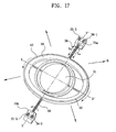
- FIG.17 is a schematic view illustrating a micro mirror device being driven to the direction of Y axis by the electromagnetic force according to the present invention, wherein a first conductor (42) electrically connected to first Y axis driving electrodes (31-1, 31-2) formed on the pair of supports (75a,75b) is formed on an outer elastic flexible structure (58) and the gimbal (56). A second conductor (43) electrically connected to second Y axis driving electrodes (34-1, 34-2) is formed on the outer elastic flexible structure (58) and the gimbal (56). Therefore, the first and second conductors (42, 43) are symmetrically formed.
- the gimbal (56) rotates about the Y axis to a predetermined degree.
- the micro mirror device can rotates on the X axis defined by the inner elastic flexible structure (57) and also on the Y axis defined by the outer elastic flexible structure (58), and movement to each axial direction is not affected by the gimbal (56) structure enabling an independent control, such that a micro mirror device having a random angle within a 2-D plane can be embodied.
- FIG.18 is a schematic view illustrating a micro mirror device driven by an electrostatic force according to the present invention.
- a first comb electrode (71) is symmetrically formed relative to a part of the outer frame (52) based on the first line (P1) connecting the pair of elastic flexible structures (55).
- the first comb electrode (71) is formed symmetrically relative to the part of the outer frame (52) formed perpendicular to the elastic flexible structures (55) for electrostatic driving.
- a second comb electrode (not shown) is formed at a lower part engaged with the first comb electrode (71), being distanced from the lower part of the first combe electrode (71).
- a first comb electrode (71-1) and a second comb electrode (71-2) are each spaced a predetermined distance apart, and the second comb electrode (71-2) is formed at an area engaged with the first comb electrode (71-1).
- the micro mirror device according to the present invention may be driven by formation of a piezoelectric material diaphragm at one side of the micro mirror, or by thermal deformation of structures, in addition to the driving methods employing the electromagnetic force or electrostatic force.
- micro mirror device may be embodied by MxN micro mirror array where the array is formed by M rows and N columns of matrix structure.
- the micro mirror device array comprises: a substrate; and a micro mirror device formed in arrays of rows and columns on a top surface of the substrate, wherein the micro mirror device comprises: a mirror plate including a diaphragm formed with a reflection facet reflecting an incident beam and a support frame disposed underneath the diaphragm to support the diaphragm; an outer frame formed at a position distanced from a periphery of the mirror plate; a plurality of connectors connecting the mirror plate to the outer frame; and a pair of elastic flexible structures symmetrically formed relative to the mirror plate, and connected to the outer frame and a pair of supports for floating the mirror plate and the outer frame from thereunder.
- the micro mirror device array comprises: a substrate; and a micro mirror device formed in arrays of rows and columns on a top surface of the substrate, wherein the micro mirror device comprises: a mirror plate including a diaphragm formed with a reflection facet reflecting an incident beam and a support frame disposed underneath the diaphragm to support the diaphragm; an outer frame formed at a position distanced from a periphery of the mirror plate; a plurality of connectors connecting the mirror plate to the outer frame; a gimbal formed at a position distanced from a periphery of the outer frame; a pair of inner elastic flexible structures connected to the gimbal and the outer frame and symmetrically formed relative to the mirror plate; and a pair of outer elastic flexible structures symmetrically formed relative to the mirror plate, and connected to the gimbal and a pair of supports for floating the mirror plate, the outer frame and the gimbal from thereunder.
- the micro mirror device comprises: a mirror plate including a diaphragm formed
- the micro mirror device according to the present invention can be embodied by MxN micro mirror array on a substrate where the array is formed by M numbers of rows and N numbers of columns of matrix structure.
- an outer frame can be formed at a position distanced from a mirror plate, thereby decreasing a dynamic deformation of the mirror plate, thereby preventing degradation of beam reflected from the mirror plate, and enabling to maintain a balance of the mirror plate.
- a frame structure supporting a diaphragm of a mirror plate is made to be thinner as it is distanced from a central axis of the mirror plate, thereby reducing a dynamic deformation of the mirror plate to a great extent and embodying the lightness of the device.
Landscapes
- Physics & Mathematics (AREA)
- Engineering & Computer Science (AREA)
- General Physics & Mathematics (AREA)
- Optics & Photonics (AREA)
- Computer Hardware Design (AREA)
- Microelectronics & Electronic Packaging (AREA)
- Mechanical Engineering (AREA)
- Mechanical Light Control Or Optical Switches (AREA)
- Micromachines (AREA)
- Mechanical Optical Scanning Systems (AREA)
- Facsimile Heads (AREA)
- Laser Beam Printer (AREA)
Abstract
Description
- Pursuant to 35 U.S.C..sctn. 119(a), this application claims the benefit of earlier filing date and right of priority to
Korean Patent Application Nos. 2005-0078755, filed on Aug. 26, 2005 - This description relates to a micro-mirror device and an array thereof. With recent advances in optical devices, various techniques which use light as a medium for inputting and outputting lots of information and for information transmission have been on the rise. Among them, there is a method of scanning beams emergent from a light source such as a barcode scanner or a scanning laser display.
- Depending on the applications thereof, beam scanning techniques are required to vary in scanning speed and range. In conventional beam scanning techniques, various scanning speeds and ranges are achieved mainly by controlling the incident angle of beam with regard to a reflection facet of an operational mirror, such as a galvanic mirror or a rotating polygon mirror.
- Indeed, a galvanic mirror is appropriate for applications that demand scanning speeds of several tens of hertz (Hz), while the polygon mirror can implement scanning speeds of several kilohertz (kHz).
- According to the development of related technologies, extensive efforts have been made to apply beam scanning techniques to new devices or to improve the performance of the pre-existing devices having the beam scanning techniques applied thereto. Representative examples thereof include projection display systems, HMDs (head mounted displays) and laser printers.
- In systems where the beam scanning technique of such a high spatial resolution is employed, a scanning mirror is generally provided for allowing a high scanning speed and a large angular displacement or a tilting angle.
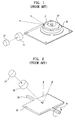
- With reference to FIG. 1, a conventional scanning apparatus employing a polygon mirror is schematically shown. In the scanning apparatus, as shown in FIG. 1, a beam emergent from a
light source 10 travels through anoptical unit 11 including various lenses and is reflected by a polygon mirror 12. As the polygon mirror 12 is rotated by a drivingmotor 13 formed underneath the polygon mirror 12, the incident beam can be scanned in the direction defined by the rotating direction (A) of the polygon mirror 12. - Generally, the polygon mirror 12 is usually mounted on the rotating
motor 13 rotating at a high speed, so that the scanning speed depends on or proportional to the angular velocity of the polygon mirror 12. - As the scanning speed depends on or proportional to the rotational angular speed of the polygon mirror 12, a limited rotation speed of the motor leads to the limitation in increasing the scanning speed of the polygon mirror 12, resulting in difficulty or inadequacy for high resolution displays.
- In addition, it is difficult to decrease the overall size of a system and the consumption of power due to the driving motor, which has fundamental problems of friction noise and contributes to an increase in production cost because of its complex structures. As one of the attempts to solve these problems, a micro mirror has been presented.
- With reference to FIG. 2, a conventional scanning apparatus employing a micro mirror is schematically shown. In the scanning apparatus, as shown in FIG. 2, a beam emergent from a
light source 20 travels through anoptical unit 21 including various lenses and is reflected by amicro mirror 22. - In other words, a
micro mirror 22 is rotated ontorsion beam 23 as axes formed at both sides of themicro mirror 22 so that the beam incident on themicro mirror 22 can be scanned in the direction defined by the rotating direction (B) of themicro mirror 22. - As for the
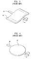
micro mirror 22, it allows a scanning apparatus to scan bi-directionally and at a high speed of tens of KHz, so that it is adequate for high resolution displays. - However, if the micro mirror is driven at a high scanning speed under a harsh condition, as shown in FIG.3, the
micro mirror 22 is generated with a dynamic deflection to distort a reflection facet to result in the reflected beam being degraded. - The
micro mirror 22 may be manufactured in various shapes depending on any particular application, and generally it comes and is used in the shape of a square, a rectangle, a circle, an oval and a lozenge. Themicro mirror 22 shows various dynamic deflections according to its shape. - FIG.5 is a graph illustrating a simulation of a dynamic deflection of a round micro mirror of FIG.4, where the round micro mirror of FIG.4 rotates to both directions about an axis defined by the
torsion beams 28 to produce a dynamic deflection as illustrated in FIG.5. - Accordingly, the present invention has been made keeping in mind the aforementioned problems and an object of the present invention is to provide a micro mirror device and an array thereof configured to form an outer frame at a position distanced from a mirror plate, thereby decreasing a dynamic deformation of the mirror plate and preventing degradation of beam reflected from the mirror plate.
- In an aspect of the invention, a micro mirror device comprises: a mirror plate including a diaphragm formed with a reflection facet reflecting an incident beam and a support frame disposed underneath the diaphragm to support the diaphragm; an outer frame formed at a position distanced from a periphery of the mirror plate; a plurality of connectors connecting the mirror plate to the outer frame; and a pair of elastic flexible structures symmetrically formed based on the mirror plate, and connected to the outer frame and a pair of supports for floating the mirror plate and the outer frame from thereunder.
- In another aspect of the invention, a micro mirror device comprises: a mirror plate including a diaphragm formed with a reflection facet reflecting an incident beam and a support frame disposed underneath the diaphragm to support the diaphragm; an outer frame formed at a position distanced from a periphery of the mirror plate; a plurality of connectors connecting the mirror plate to the outer frame; a gimbal formed at a position distanced from a periphery of the outer frame; a pair of inner elastic flexible structures connected to the gimbal and the outer frame and symmetrically formed based on the mirror plate; and a pair of outer elastic flexible structures symmetrically formed based on the mirror plate, and connected to the gimbal and a pair of supports for floating the mirror plate, the outer frame and the gimbal from thereunder.
- In yet another aspect of the invention, a micro mirror device array comprises: a substrate; and a micro mirror device formed in arrays of rows and columns on a top surface of the substrate, wherein the micro mirror device comprises: a mirror plate including a diaphragm formed with a reflection facet reflecting an incident beam and a support frame disposed underneath the diaphragm to support the diaphragm; an outer frame formed at a position distanced from a periphery of the mirror plate; a plurality of connectors connecting the mirror plate to the outer frame; and elastic flexible structures symmetrically formed based on the mirror plate, and connected to the outer frame and a pair of supports for floating the mirror plate and the outer frame from thereunder.
-
- FIG.1 is a schematic perspective view of a beam scanning apparatus employing a conventional polygon mirror.
- FIG.2 is a schematic perspective view of a conventional beam scanning apparatus employing a micro mirror device.
- FIG. 3 is a schematic view illustrating a dynamic deflection of a micro mirror device.
- FIG.4 is a schematic perspective view illustrating a round micro mirror according to prior art.
- FIG.5 is a graph illustrating a simulation of a dynamic deflection of a round micro mirror device of FIG.4.
- FIG.6 is a perspective view illustrating an exemplary embodiment of a micro mirror device according to the present invention.
- FIG.7 is a schematic conceptual view illustrating a connector of a micro mirror device according to the present invention.
- FIG.8 is a graph illustrating a simulation of a dynamic deformation of a micro mirror device according to the present invention.
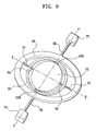
- FIG.9 is a perspective view illustrating another exemplary embodiment of a micro mirror device according to the present invention.
- FIG.10 is a schematic conceptual view illustrating a connector of the micro mirror device of FIG.9 according to the present invention.
- FIG. 11 is a perspective view illustrating a shape of a connector of a micro mirror device according to an embodiment of the present invention.
- FIG.12 is a perspective view illustrating a shape of a frame of a mirror plate according to an embodiment of the present invention.
- FIG. 13 is a perspective view illustrating a shape of a frame of a mirror plate according to another embodiment of the present invention.
- FIG. 14 is a perspective view illustrating a shape of a frame of a mirror plate according to still another embodiment of the present invention.
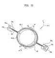
- FIG.15 is a schematic view illustrating a micro mirror device of electromagnetic force driving type according to the present invention.
- FIG.16 is a schematic view illustrating a micro mirror device being driven to the direction of X axis by the electromagnetic force according to the present invention.
- FIG.17 is a schematic view illustrating a micro mirror device being driven to the direction of Y axis by the electromagnetic force according to the present invention.
- FIG.18 is a schematic view illustrating a micro mirror device driven by an electrostatic force according to the present invention.
- FIG.19 is a schematic view illustrating an electrostatic force generated between comb-type electrodes of the micro mirror device of FIG.18.
- Reference will now be made in detail to the preferred embodiments of the present invention, examples of which are illustrated in the accompanying drawings. Wherever possible, the same reference numbers will be used throughout the drawings to refer to the same or like parts. These embodiments, offered not to limit but only to exemplify and teach the invention, are shown and described in sufficient detail to enable those skilled in the art to practice the invention. Thus, where appropriate to avoid obscuring the invention, the description may omit certain information known to those of skill in the art.
- FIG.6 is a perspective view illustrating an exemplary embodiment of a micro mirror device according to the present invention. Referring to FIG.6, the micro mirror device comprises: a mirror plate (51) including a diaphragm formed with a reflection facet reflecting an incident beam and a support frame disposed underneath the diaphragm to support the diaphragm; an outer frame (52) formed at a position distanced from a periphery of the mirror plate (51); a plurality of connectors (53A,53B,54) connecting the mirror plate (51) to the outer frame (52); and a pair of elastic flexible structures (55) symmetrically formed relative to the mirror plate (51), and connected to the outer frame (52) and a pair of supports (75) for floating the mirror plate (51) and the outer frame (52) from thereunder.
- At a periphery of the mirror plate (51) there is disposed the outer frame (52) concentrically formed with the mirror plate (51) for dispersing a dynamic deformation of the mirror plate (51), and the mirror plate (51) and the outer frame (52) are simultaneously rotated about elastic flexible structures (55) as an axis to reflect an incident beam to a predetermined direction.
- Referring to FIG.7, the outer frame (52) is distanced from the mirror plate (51), and the plurality of connectors (53A,53B,54) connecting the outer frame (52) to the mirror plate (51) are formed on a first line (P1) connecting a pair of elastic flexible structures (55), and include a first connector (54) symmetrically formed relative to the mirror plate (51), and a second connector formed on a second line (P2) perpendicular to the first line (P1), and symmetrically formed relative to the mirror plate (51).
- Preferably, the second connector is formed on the second line (P2) perpendicular to the first line (P1), and includes connectors (53A-1, 53A-2, 53B-1, 53B-2) symmetrically formed relative to the mirror plate (51), in order to minimize the dynamic deflection of the micro mirror.
- Because the second connector includes connectors (53A-1, 53A-2, 53B-1, 53B-2) symmetrically formed relative to the mirror plate (51) each formed on the second line (P2) perpendicular to the first line (P1), there are formed spaces (91,92) between the mirror plate (51) and the outer frame (52) by the connectors (53A-1, 53A-2, 53B-1, 53B-2), thereby allowing the dynamic deflection of the mirror plate (51) to be absorbed by the outer frame (52).
- Without the second connector, the mirror plate (51) and the outer frame (52) would be directly connected, and if the mirror plate and the outer frame are directly connected without the second connector, the outer frame (52) cannot absorb the dynamic deflection, and may only flutter like the mirror plate (51).
- Meanwhile, the first connector (54) may not be formed on the first line (P1) connecting the pair of elastic flexible structures (55), but the second connector must be formed on the second line (P2) perpendicular to the first line (P1).
- The elastic flexible structures (55) serve to connect the outer frame (52) to a pair of supports (75) to float the mirror plate (51) and the outer frame (52) from thereunder, and function as rotational axes when the micro mirror device is driven to provide a restoring torque. At this time, the supports (75) are partially and schematically shown. As noted above, in case the outer frame (52) is formed at the periphery of the mirror plate (51) and rotates about an axis defined by the elastic flexible structures (55), the dynamic deflection of the mirror plate (51) can be absorbed by the outer frame (52) to enable to keep balance of the mirror plate (51).
- FIG.8 is a graph illustrating a simulation of a dynamic deformation of a micro mirror device according to the present invention, where it can be noted that the dynamic deformation of the micro mirror has markedly decreased over that of the case shown in FIG.5 according to the prior art.
- FIG.9 is a perspective view illustrating another exemplary embodiment of a micro mirror device according to the present invention. The micro mirror device comprises: a mirror plate (51) including a diaphragm formed with a reflection facet reflecting an incident beam and a support frame disposed underneath the diaphragm to support the diaphragm; an outer frame (52) formed at a position distanced from a periphery of the mirror plate (51); a plurality of connectors (53A,53B,54) connecting the mirror plate (51) to the outer frame (52); a gimbal (56) formed at a position distanced from a periphery of the outer frame (52); a pair of inner elastic flexible structures (57) connected to the gimbal (56) and the outer frame (52) and symmetrically formed relative to the mirror plate (51); and a pair of outer elastic flexible structures (58) symmetrically formed relative to the mirror plate (51), and connected to the gimbal (56) and a pair of supports (75) for floating the mirror plate (51), the outer frame (52) and the gimbal (56) from thereunder.
- At a periphery of the mirror plate (51) there is disposed the outer frame (52) concentrically formed with the mirror plate (51) distanced from the mirror plate (51), and at the periphery of the outer frame (52) there is formed the gimbal (56) concentrically formed with the mirror plate (51) and distanced from the outer frame (52).
- Referring to FIG.10, the plurality of connectors (53A,53B,54) connecting the outer frame (52) to the mirror plate (51) are formed on the first line (P1) connecting the pair of elastic flexible structures (55), and include a first connector (54) symmetrically formed relative to the mirror plate (51) and formed on the second line (P2) perpendicular to the first line (P1), and a second connector formed on the first line (P1) connecting the pair of elastic flexible structures (55) and symmetrically formed relative to the mirror plate (51).
- The gimbal (56) is connected to the outer frame (52) by the inner elastic flexible structure (57), and connected to the support (75) by the outer elastic flexible structure (58) symmetrically formed on a line perpendicular to the inner elastic flexible structure (57).
- The outer elastic flexible structure (58) floats the mirror plate (51), the outer frame (52) and the gimbal (56) from thereunder by connecting the gimbal (56) to the support (75). At this time the support (75) is schematically and partially shown.
- The inner and outer elastic flexible structures (57, 58) provide restoring torque when the micro mirror device is driven and function as rotational axes.
- In other words, the outer frame (52) is rotated about an axis defined by the inner elastic flexible structure (57) (an axis connecting X to X' as depicted in FIG.9, and hereinafter referred to as X axis), and the gimbal (56) is rotated about an axis defined by the outer elastic flexible structure (58) (an axis connecting Y to Y' as shown in FIG.9, and hereinafter referred to as Y axis).
- The micro mirror device thus structured can provide freedom of rotational movement about two axes. In other words, a rotational movement about an X axis defined by the inner elastic flexible structure (57) and a rotational movement about a Y axis defined by the outer elastic flexible structure (58) are possible, and the movement to each axial direction is not affected by the gimbal (56) structure to enable an independent control, such that a micro mirror device having an arbitrary angle within a two dimensional plane can be embodied.
- In FIGS. 6 and 9, the mirror plate may be manufactured in one of various shapes such as a round shape, or either an oval shape or rectangular shape. The outer frame (52) and the gimbal (56) may be manufactured in various shapes according to the shape of the mirror plate (51). At this time, the mirror plate (51) may be formed in a lozenge or a diamond shape.
- However, the mirror plate (51) is preferred to be manufactured in a round or an oval shape in order to minimize the dynamic deformation of the mirror plate (51), and the outer frame (52) and the gimbal (56) are preferably manufactured in a ring shape.
- Furthermore, the first and second connectors that connect the outer frame (52) to the mirror plate (51) may be manufactured with different positions, shapes and numbers thereof, and if the positions and shapes of the first and second connectors are varied, shapes of the dynamic deformation of the micro mirror device are also varied. However, if the outer frame (52) is connected by the mirror plate (51) and a single connector, the dynamic deformation cannot be absorbed by the outer frame (52), and if the first and second connectors are too broad, the dynamic deformation increases markedly, which should be taken into account in manufacturing thereof.
- The elastic flexible structure connecting the micro mirror to the support (75) may be formed in various shapes such as a torsion beam type, a V-shaped beam type and a meander type shape according to a driving direction and a driving method of the micro mirror device, and a combination thereof may be also possible.
- FIG. 11 is a perspective view illustrating an exemplary embodiment of a connector having a different shape from that of FIG.6, where the second connector perpendicular to the first connector (54) includes plural (two) connectors at two areas, while a single connector (61) is formed at each (two) area in FIG.11.
- As depicted in FIG.11, if the second connector is singularly formed, it is easy to manufacture, and this kind of structure may be applied to a micro mirror device having two rotational axes.
- A mirror plate of the micro mirror device includes a diaphragm having a reflection facet for reflecting the incident beam, and a support frame for supporting the diaphragm and for preventing the mirror plate from being dynamically deformed during scanning. The reflection facet is preferably made of one of a metal film, a dielectric film, and a film layered by the two elements.
- Furthermore, the support frame may have the same shape as that of the diaphragm, but other shapes may include, for example, a single structure of a diamond or a starfish shape, or a structure arrayed in a certain shape.
- FIG.12 is a perspective view illustrating an exemplary shape of a frame of a mirror plate according to the present invention, where a support frame (59) has a shape of a saw-toothed array, parts of which are symmetrically V-cut.
- If the mirror plate is formed with the support frame (59) in a saw-toothed array on a round diaphragm (60), instead of a round support frame on a round diaphragm (60), mass and inertia of the support frame can be partially reduced to thereby enable to limit the dynamic deformation of the micro mirror device.
- In other words, a total deformation by the dynamic deformation of the micro mirror device is determined by a length from a rotational axis to a distal end of a mirror plate (i.e., shape of the mirror plate) and a thickness of the mirror plate, where, as a thickness of the support frame has a larger value than that of the diaphragm, the size of the dynamic deformation is determined by the support frame when the micro mirror device is driven.
- Therefore, if the support frame (59) is partially removed to get a saw-toothed shape of array, the mass and inertial of the support frame can be partially decreased to thereby enable to limit the dynamic deformation of the micro mirror device.
- Furthermore, if a support frame is formed with a saw-toothed shape of array as shown in FIG.12 instead of a single structure of a predetermined shape, there is an advantage in that an overall strength of a diaphragm of a mirror plate can be enhanced along with the reduced effect of the dynamic deformation.
- The dynamic deformation decreases if mass gradually decreases from the center of the mirror plate to a periphery thereof when the micro mirror device is driven. Similarly, the dynamic deformation can be reduced by adopting any type of support frame taking the lion's share of the mass of the mirror plate, the support frame so made as to be reduced in the mass from the center of the mirror plate to the periphery thereof.
- For example, as shown in FIG.13, if a support frame (59) is used that has a saw-tooth shaped array and that has a thickness gradually tapering off from the center of the mirror plate to the periphery thereof, mass and inertia of the support frame can be significantly reduced to limit the dynamic deformation to a great extent.
- With reference to FIG.14, if a plurality of grooves (59-1) is formed on the saw-toothed array of the support frame (59), there is an advantage in that mass and inertia are further reduced. The shapes of grooves (59-1) may vary but in the present invention, each shape of the grooves is hexagonal like a honeycomb. As noted above, if a support frame structure with a variety of shapes is formed with grooves, or thickness is differently adjusted according to the position of the support frame, the dynamic deformation of the micro mirror device can be reduced.
- Meanwhile, the micro mirror device additionally needs a driving unit for applying a driving torque or a driving force as a means for realizing the scanning function, and an electrostatic method, an electromagnetic method, a thermal method or a piezoelectric method may be employed for driving the micro mirror device.
- FIG.15 is a schematic view illustrating a micro mirror device of electromagnetic force driving type according to the present invention. The micro mirror device comprises: a pair of first electrodes (73a, 73b) formed on one support (75a) out of a pair of supports (75a, 75b); a pair of second electrodes (73c,73d) formed at the other support (75b) out of the pair of supports (75a, 75b); and a pair of conductors (70-1, 70-2) connected from the first electrodes (73a, 73b) to the second electrodes (73c,73d).
- As noted above, the first conductor (70-1) is formed on an upper hemisphere of the elastic flexible structure (55) and the outer frame (52), and the second conductor (70-2) is formed on a lower hemisphere of the elastic flexible structure (55) and the outer frame (52). The first and second conductors (70-1, 70-2) are electrically connected to the electrodes (73a, 73b, 73c, 73d) formed on the supports (75a, 75b).
- If current flows on the first and second conductors (70-1, 70-2), the upper hemisphere of the outer frame (52) receives force in the direction of -z while the lower hemisphere of the outer frame (52) receives force in the direction of +z according to Fleming's left hand rule as shown in FIG. 15, such that the mirror plate (51) rotates about an axis defined by the elastic flexible structure (55).
- The first and second conductors (70-1, 70-2) may be formed in one single conductor. In other words, the single conductor may be formed in such a fashion as to be disposed on one side of an elastic flexible structure (55) of the symmetrically formed elastic flexible structures (55), branched out on the outer frame (52) and joined again on the other side of the elastic flexible structure (55).
- FIG.16 is a schematic view illustrating a micro mirror device being driven to the direction of X axis by the electromagnetic force according to the present invention, wherein first X axis driving electrodes (32-1, 32-2) are formed on a predetermined area of the support (75), and a first conductor (40) electrically connected to the first X axis driving electrodes (32-1, 32-2) is continuously formed on an elastic flexible structure (58), a gimbal (56), an inner elastic flexible structure (57), a mirror plate (51) and the outer frame (52).
- Furthermore, second X axis driving electrodes (33-1, 33-2) are formed on the other area of the support (75) and a second conductor (41) electrically connected to the second X axis driving electrodes (33-1, 33-2) is formed on the elastic flexible structure (58), the gimbal (56), the inner elastic flexible structure (57), the mirror plate (51) and the outer frame (52) in the symmetrical formation with the first conductor (40).
- If voltage is applied to the first X axis driving electrodes (32-1, 32-2) and the second X axis driving electrodes (33-1, 33-2) to allow currents (I 22, I 23) to flow in the first and second conductors (40, 41), the mirror plate (51) rotates about the X axis to a predetermined degree.
- FIG.17 is a schematic view illustrating a micro mirror device being driven to the direction of Y axis by the electromagnetic force according to the present invention, wherein a first conductor (42) electrically connected to first Y axis driving electrodes (31-1, 31-2) formed on the pair of supports (75a,75b) is formed on an outer elastic flexible structure (58) and the gimbal (56). A second conductor (43) electrically connected to second Y axis driving electrodes (34-1, 34-2) is formed on the outer elastic flexible structure (58) and the gimbal (56). Therefore, the first and second conductors (42, 43) are symmetrically formed.
- If voltage is applied to the first Y axis driving electrodes (31-1, 31-2) and the second Y axis driving electrodes (34-1, 34-2) to allow currents to flow in the first and second conductors (42, 43), the gimbal (56) rotates about the Y axis to a predetermined degree.
- As described in FIGS. 16 and 17, the micro mirror device can rotates on the X axis defined by the inner elastic flexible structure (57) and also on the Y axis defined by the outer elastic flexible structure (58), and movement to each axial direction is not affected by the gimbal (56) structure enabling an independent control, such that a micro mirror device having a random angle within a 2-D plane can be embodied.
- FIG.18 is a schematic view illustrating a micro mirror device driven by an electrostatic force according to the present invention.
- Referring to FIG.18 in association with FIG.7, a first comb electrode (71) is symmetrically formed relative to a part of the outer frame (52) based on the first line (P1) connecting the pair of elastic flexible structures (55). In other words, the first comb electrode (71) is formed symmetrically relative to the part of the outer frame (52) formed perpendicular to the elastic flexible structures (55) for electrostatic driving. At this time, a second comb electrode (not shown) is formed at a lower part engaged with the first comb electrode (71), being distanced from the lower part of the first combe electrode (71).
- If voltage is applied to the first comb electrode (71) and the second comb electrodes, an electrostatic force is generated between the first and second comb electrodes, and mutually pulling force is generated to thereby drive the micro mirror device.
- Referring now to FIG.19, a first comb electrode (71-1) and a second comb electrode (71-2) are each spaced a predetermined distance apart, and the second comb electrode (71-2) is formed at an area engaged with the first comb electrode (71-1).
- If voltage (+) is applied to the first comb electrode (71-1) and voltage (-) is applied to the second comb electrode (71-2), a mutually pulling force is generated between the first and second comb electrodes (71-1, 71-2) to drive the micro mirror device.
- As noted above, the micro mirror device according to the present invention may be driven by formation of a piezoelectric material diaphragm at one side of the micro mirror, or by thermal deformation of structures, in addition to the driving methods employing the electromagnetic force or electrostatic force.
- Furthermore, the micro mirror device according to the present invention may be embodied by MxN micro mirror array where the array is formed by M rows and N columns of matrix structure.
- In other words, the micro mirror device array comprises: a substrate; and a micro mirror device formed in arrays of rows and columns on a top surface of the substrate, wherein the micro mirror device comprises: a mirror plate including a diaphragm formed with a reflection facet reflecting an incident beam and a support frame disposed underneath the diaphragm to support the diaphragm; an outer frame formed at a position distanced from a periphery of the mirror plate; a plurality of connectors connecting the mirror plate to the outer frame; and a pair of elastic flexible structures symmetrically formed relative to the mirror plate, and connected to the outer frame and a pair of supports for floating the mirror plate and the outer frame from thereunder.
- Furthermore, the micro mirror device array comprises: a substrate; and a micro mirror device formed in arrays of rows and columns on a top surface of the substrate, wherein the micro mirror device comprises: a mirror plate including a diaphragm formed with a reflection facet reflecting an incident beam and a support frame disposed underneath the diaphragm to support the diaphragm; an outer frame formed at a position distanced from a periphery of the mirror plate; a plurality of connectors connecting the mirror plate to the outer frame; a gimbal formed at a position distanced from a periphery of the outer frame; a pair of inner elastic flexible structures connected to the gimbal and the outer frame and symmetrically formed relative to the mirror plate; and a pair of outer elastic flexible structures symmetrically formed relative to the mirror plate, and connected to the gimbal and a pair of supports for floating the mirror plate, the outer frame and the gimbal from thereunder.
- Consequently, the micro mirror device according to the present invention can be embodied by MxN micro mirror array on a substrate where the array is formed by M numbers of rows and N numbers of columns of matrix structure.
- As apparent from the foregoing, there is an advantage in the micro mirror device and an array thereof thus described according to the present invention in that an outer frame can be formed at a position distanced from a mirror plate, thereby decreasing a dynamic deformation of the mirror plate, thereby preventing degradation of beam reflected from the mirror plate, and enabling to maintain a balance of the mirror plate.
- Furthermore, there is another advantage in that a frame structure supporting a diaphragm of a mirror plate is made to be thinner as it is distanced from a central axis of the mirror plate, thereby reducing a dynamic deformation of the mirror plate to a great extent and embodying the lightness of the device.
- It will be appreciated by those of skill in the art that a new and useful micro mirror device and an array thereof has been described herein. In view of the many possible embodiments to which the principles of this invention may be applied, however, it should be recognized that the embodiments described herein with respect to the drawing figures are meant to be illustrative only and should not be taken as limiting the scope of invention. For example, those of skill in the art will recognize that the illustrated embodiments can be modified in arrangement and detail without departing from the spirit of the invention. Therefore, the invention as described herein contemplates such embodiments as may come within the scope of the following claims and equivalents thereof.
Claims (20)
- A micro mirror device comprising: a mirror plate including a diaphragm formed with a reflection facet reflecting an incident beam and a support frame disposed underneath the diaphragm to support the diaphragm; an outer frame formed at a position distanced from a periphery of the mirror plate; a plurality of connectors connecting the mirror plate to the outer frame; and a pair of elastic flexible structures symmetrically formed relative to the mirror plate, and connected to the outer frame and a pair of supports for floating the mirror plate and the outer frame from thereunder.
- The device as defined in claim 1, wherein the mirror plate is one of a circle shape, an oval shape and a rectangular shape.
- The device as defined in claim 1, wherein the outer frame is of a ring shape.
- The device as defined in claim 1, wherein each of the pair of elastic flexible structures is one of a torsion beam type, a V-shaped beam type and a meander type shape, or a combination thereof.
- The device as defined in claim 1, wherein the reflection facet is made of a metal film, a dielectric film, or a film layered by the two elements.
- The device as defined in claim 6, wherein the plurality of connectors connecting the outer frame to the mirror plate comprises: a first connector formed on a first line connecting the pair of elastic flexible structures, and symmetrically formed based on the mirror plate; and a second connector formed on a second line perpendicular to the first line, and symmetrically formed based on to the mirror plate.
- The device as defined in claim 1, wherein the plurality of connectors connecting the outer frame to the mirror plate comprises: a first connector formed on a first line connecting the pair of elastic flexible structures, and symmetrically formed based on the mirror plate; and a second connector symmetrically formed relative to the second line perpendicular to the first line, and symmetrically formed based on the mirror plate.
- The device defined in claim 1, wherein the support frame is tapered off in thickness thereof as it is distanced from a center.
- The device as defined in claim 1, wherein the support frame is partially arrayed with a saw-tooth shape.
- The device as defined in claim 1 further comprising: a pair of first electrodes formed on one support out of a pair of supports; a pair of second electrodes formed at the other support out of the pair of supports; and a pair of conductors formed on the pair of elastic flexible structures and the outer frame so as to be connected from the first electrodes to the second electrodes.
- The device as defined in claim 1 further comprising: a first comb electrode symmetrically formed on a part of the outer frame based on the first line connecting the pair of elastic flexible structures; and a second comb electrode formed at a lower part engaged with the first comb electrode and formed being distanced from the lower part of the first comb electrode.
- A micro mirror device comprising: a mirror plate including a diaphragm formed with a reflection facet reflecting an incident beam and a support frame disposed underneath the diaphragm to support the diaphragm; an outer frame formed at a position distanced from a periphery of the mirror plate; a plurality of connectors connecting the mirror plate to the outer frame; a gimbal formed at a position distanced from a periphery of the outer frame; a pair of inner elastic flexible structures connected to the gimbal and the outer frame and symmetrically formed based on the mirror plate; and a pair of outer elastic flexible structures symmetrically formed based on the mirror plate, and connected to the gimbal and a pair of supports for floating the mirror plate, the outer frame and the gimbal from thereunder.
- The device as defined in claim 12, wherein the mirror plate is one of a circle shape, an oval shape and a rectangular shape.
- The device as defined in claim 1, wherein the reflection facet is made of one of a metal film, a dielectric film, and a film layered by the two elements.
- The device as defined in claim 12, wherein the plurality of connectors connecting the outer frame to the mirror plate comprises: a connector formed on a first line connecting the pair of elastic flexible structures, and symmetrically formed based on the mirror plate; and the other connector formed on a second line perpendicular to the first line, and symmetrically formed based on to the mirror plate.
- The device as defined in claim 12, wherein part of the support frame is formed with a saw-toothed array.
- The device as defined in claim 12 further comprising: a pair of first electrodes formed on one support out of a pair of supports; a pair of second electrodes formed at the other support out of the pair of supports; and a pair of conductors formed on the pair of elastic flexible structures and the outer frame so as to be connected from the first electrodes to the second electrodes.
- The device as defined in claim 12 further comprising: a first comb electrode symmetrically formed on a part of the outer frame based on the first line connecting the pair of elastic flexible structures; and a second comb electrode formed at a lower part engaged with the first comb electrode and formed being distanced from the lower part of the first comb electrode.
- A micro mirror device array comprising: a substrate; and a micro mirror device formed in arrays of rows and columns on a top surface of the substrate, wherein the micro mirror device comprises: a mirror plate including a diaphragm formed with a reflection facet reflecting an incident beam and a support frame disposed underneath the diaphragm to support the diaphragm; an outer frame formed at a position distanced from a periphery of the mirror plate; a plurality of connectors connecting the mirror plate to the outer frame; and elastic flexible structures symmetrically formed based on the mirror plate, and connected to the outer frame and a pair of supports for floating the mirror plate and the outer frame from thereunder.
- The array as defined in claim 19, wherein the micro mirror device further comprises a gimbal formed at a position distanced from a periphery of the outer frame, and wherein the elastic flexible structures comprise: a pair of inner elastic flexible structures connected to the gimbal and the outer frame and symmetrically formed based on the mirror plate; and a pair of outer elastic flexible structures symmetrically formed based on the mirror plate, and connected to the gimbal and a pair of supports for floating the mirror plate, the outer frame and the gimbal from thereunder.
Applications Claiming Priority (1)
| Application Number | Priority Date | Filing Date | Title |
|---|---|---|---|
| KR1020050078755A KR100743315B1 (en) | 2005-08-26 | 2005-08-26 | Micro Mirror Device and Micro Mirror Device Array Using the Same |
Publications (2)
| Publication Number | Publication Date |
|---|---|
| EP1757972A1 true EP1757972A1 (en) | 2007-02-28 |
| EP1757972B1 EP1757972B1 (en) | 2013-10-02 |
Family
ID=37453055
Family Applications (1)
| Application Number | Title | Priority Date | Filing Date |
|---|---|---|---|
| EP06291331.4A Ceased EP1757972B1 (en) | 2005-08-26 | 2006-08-18 | Micro-mirror device and array thereof |
Country Status (5)
| Country | Link |
|---|---|
| US (1) | US7567367B2 (en) |
| EP (1) | EP1757972B1 (en) |
| JP (1) | JP4457093B2 (en) |
| KR (1) | KR100743315B1 (en) |
| CN (1) | CN100552491C (en) |
Cited By (4)
| Publication number | Priority date | Publication date | Assignee | Title |
|---|---|---|---|---|
| WO2018188810A1 (en) * | 2017-04-11 | 2018-10-18 | Fraunhofer-Gesellschaft zur Förderung der angewandten Forschung e.V. | Micromechanical mirror device |
| WO2021078487A1 (en) * | 2019-10-21 | 2021-04-29 | Robert Bosch Gmbh | Micromechanical oscillator system |
| EP3865452A1 (en) * | 2020-02-14 | 2021-08-18 | Google LLC | Variable mesh low mass mems mirrors |
| EP3485313B1 (en) * | 2016-07-18 | 2024-05-22 | Carl Zeiss SMT GmbH | Sensor device |
Families Citing this family (36)
| Publication number | Priority date | Publication date | Assignee | Title |
|---|---|---|---|---|
| JP5286906B2 (en) | 2007-06-08 | 2013-09-11 | 大日本印刷株式会社 | Piezoelectric mirror device, optical apparatus using the same, and method of manufacturing piezoelectric mirror device |
| KR101341522B1 (en) * | 2007-11-07 | 2013-12-16 | 엘지전자 주식회사 | Projector |
| TWI416168B (en) | 2010-02-05 | 2013-11-21 | Ind Tech Res Inst | Optical multi-ring scanner |
| CN102193189B (en) * | 2010-03-01 | 2012-11-28 | 财团法人工业技术研究院 | Optical multi-ring scanning element |
| JP5614167B2 (en) * | 2010-08-18 | 2014-10-29 | 株式会社リコー | Optical deflector, optical scanning device, image forming apparatus, and image projecting apparatus |
| JPWO2013027405A1 (en) | 2011-08-25 | 2015-03-05 | 株式会社ニコン | Spatial light modulation element and exposure apparatus |
| JP5857602B2 (en) * | 2011-10-03 | 2016-02-10 | ミツミ電機株式会社 | Optical scanning device |
| JP5876345B2 (en) * | 2012-03-23 | 2016-03-02 | スタンレー電気株式会社 | Optical deflector |
| JP6056179B2 (en) * | 2012-04-18 | 2017-01-11 | セイコーエプソン株式会社 | Optical scanner and image forming apparatus |
| TWI558653B (en) * | 2012-07-30 | 2016-11-21 | 先進微系統科技股份有限公司 | Oscillation structure of micro actuator |
| KR102014781B1 (en) * | 2013-01-02 | 2019-08-27 | 엘지전자 주식회사 | Scanning micro mirror package |
| WO2014122781A1 (en) * | 2013-02-08 | 2014-08-14 | パイオニア株式会社 | Actuator |
| CN105263851B (en) * | 2013-05-31 | 2017-10-13 | 罗伯特·博世有限公司 | confined membrane |
| DE102013212102A1 (en) | 2013-06-25 | 2015-01-08 | Robert Bosch Gmbh | Micromechanical component, micromirror device and production method for a micromechanical component |
| DE102013223937B4 (en) | 2013-11-22 | 2022-01-05 | Fraunhofer-Gesellschaft zur Förderung der angewandten Forschung e.V. | Micromirror array |
| DE102013224631A1 (en) | 2013-11-29 | 2015-06-03 | Robert Bosch Gmbh | Micromirror and manufacturing method for at least one micromirror that can be arranged or arranged in a micromirror device |
| DE102014207891A1 (en) * | 2014-02-17 | 2015-08-20 | Robert Bosch Gmbh | Mirror arrangement and projection device |
| JP2016139015A (en) * | 2015-01-28 | 2016-08-04 | セイコーエプソン株式会社 | Mirror device, mirror device manufacturing method, and image display apparatus |
| US10642027B2 (en) * | 2015-12-08 | 2020-05-05 | The Regents Of The University Of Michigan | 3D MEMS scanner for real-time cross-sectional endomicroscopy |
| WO2018138193A1 (en) * | 2017-01-27 | 2018-08-02 | Fraunhofer-Gesellschaft zur Förderung der angewandten Forschung e.V. | Mms, mms array, mems actuator, and method for preparing an mms |
| WO2019031420A1 (en) * | 2017-08-10 | 2019-02-14 | 浜松ホトニクス株式会社 | Mirror device |
| CN108152801B (en) * | 2017-11-10 | 2022-01-11 | 无锡英菲感知技术有限公司 | Dynamic deformation controllable micromirror |
| CN108226936B (en) * | 2017-11-10 | 2022-02-11 | 无锡英菲感知技术有限公司 | Time division sharing window laser radar system based on micro-mirror |
| CN107966810A (en) * | 2017-12-19 | 2018-04-27 | 无锡英菲感知技术有限公司 | A kind of two-dimensional scanning micro mirror |
| CN108614353B (en) * | 2018-05-10 | 2020-08-04 | 西安交通大学 | Two-dimensional deflection decoupling mechanism and deflection method based on ion-exchange polymeric metal materials |
| EP3751328B1 (en) | 2019-06-10 | 2021-10-27 | Murata Manufacturing Co., Ltd. | Two-axis mems mirror with separated drives |
| JP7665631B2 (en) * | 2020-01-16 | 2025-04-21 | マジック リープ, インコーポレイテッド | Scanning mirror system and method of manufacture |
| JP7796649B2 (en) | 2020-01-22 | 2026-01-09 | マジック リープ, インコーポレイテッド | Two mirror scanning relay optical system |
| US11796638B2 (en) * | 2020-06-18 | 2023-10-24 | Beijing Voyager Technology Co., Ltd. | Mirror assembly for light steering with flexible support structure |
| US11815627B2 (en) | 2020-06-18 | 2023-11-14 | Beijing Voyager Technology Co., Ltd. | Mirror assembly for light steering with reduced finger thickness |
| US20230023348A1 (en) | 2021-06-22 | 2023-01-26 | Calient Technologies, Inc. | Fabrication of a micro-mirror with reduced moment of inertia and mems devices |
| KR102769216B1 (en) * | 2021-10-15 | 2025-02-20 | 이화여자대학교 산학협력단 | Scanning micromirror |
| CN115542512B (en) * | 2022-10-25 | 2025-01-21 | 中国电子科技集团公司第五十四研究所 | A flexible support structure for reducing the bonding deformation of a swing mirror |
| WO2025216239A1 (en) * | 2024-04-12 | 2025-10-16 | パナソニックIpマネジメント株式会社 | Optical reflection element |
| EP4733825A1 (en) | 2024-10-28 | 2026-04-29 | Murata Manufacturing Co., Ltd. | Mems mirror with reduced deformation |
| CN119439482B (en) * | 2024-12-03 | 2025-10-24 | 北京理工大学 | A micromirror structure for reducing dynamic deformation |
Citations (8)
| Publication number | Priority date | Publication date | Assignee | Title |
|---|---|---|---|---|
| US6137926A (en) * | 1996-08-12 | 2000-10-24 | Maynard; Ronald S. | Hybrid optical multi-axis beam steering apparatus |
| US6275324B1 (en) * | 1998-12-14 | 2001-08-14 | Lucent Technologies Inc. | Micromachined tunable optical filter with controllable finesse and passband wavelength position |
| WO2001092939A1 (en) * | 2000-05-31 | 2001-12-06 | The Regents Of The University Of California | Staggered torsional electrostatic combdrive and method of forming same |
| US20040070816A1 (en) * | 2002-07-05 | 2004-04-15 | Canon Kabushiki Kaisha | Optical deflector and method of producing same |
| US20040130766A1 (en) * | 2002-11-08 | 2004-07-08 | Dewa Andrew Steven | Multilayered oscillating functional surface |
| KR20050078755A (en) | 2004-02-02 | 2005-08-08 | 삼성전기주식회사 | An apparatus for substituting the atmosphere in entrance of sintering furnace |
| US20050184351A1 (en) * | 2004-02-13 | 2005-08-25 | Yee-Chung Fu | Mems scanning mirror with trenched surface and tapered comb teeth for reducing inertia and deformation |
| EP1684108A1 (en) * | 2005-01-19 | 2006-07-26 | LG Electronics Inc. | Electromagnetic scanning micro-mirror and optical scanning device using the same |
Family Cites Families (3)
| Publication number | Priority date | Publication date | Assignee | Title |
|---|---|---|---|---|
| JP2005092174A (en) * | 2003-08-12 | 2005-04-07 | Fujitsu Ltd | Micro oscillating device |
| US6967757B1 (en) * | 2003-11-24 | 2005-11-22 | Sandia Corporation | Microelectromechanical mirrors and electrically-programmable diffraction gratings based on two-stage actuation |
| US7859167B2 (en) * | 2004-03-08 | 2010-12-28 | Panasonic Corporation | Micro actuator having tilt and vertical displacement and device having such micro actuator |
-
2005
- 2005-08-26 KR KR1020050078755A patent/KR100743315B1/en not_active Expired - Fee Related
-
2006
- 2006-08-18 EP EP06291331.4A patent/EP1757972B1/en not_active Ceased
- 2006-08-23 JP JP2006226820A patent/JP4457093B2/en not_active Expired - Fee Related
- 2006-08-24 US US11/508,821 patent/US7567367B2/en not_active Expired - Fee Related
- 2006-08-25 CN CNB2006101218540A patent/CN100552491C/en not_active Expired - Fee Related
Patent Citations (8)
| Publication number | Priority date | Publication date | Assignee | Title |
|---|---|---|---|---|
| US6137926A (en) * | 1996-08-12 | 2000-10-24 | Maynard; Ronald S. | Hybrid optical multi-axis beam steering apparatus |
| US6275324B1 (en) * | 1998-12-14 | 2001-08-14 | Lucent Technologies Inc. | Micromachined tunable optical filter with controllable finesse and passband wavelength position |
| WO2001092939A1 (en) * | 2000-05-31 | 2001-12-06 | The Regents Of The University Of California | Staggered torsional electrostatic combdrive and method of forming same |
| US20040070816A1 (en) * | 2002-07-05 | 2004-04-15 | Canon Kabushiki Kaisha | Optical deflector and method of producing same |
| US20040130766A1 (en) * | 2002-11-08 | 2004-07-08 | Dewa Andrew Steven | Multilayered oscillating functional surface |
| KR20050078755A (en) | 2004-02-02 | 2005-08-08 | 삼성전기주식회사 | An apparatus for substituting the atmosphere in entrance of sintering furnace |
| US20050184351A1 (en) * | 2004-02-13 | 2005-08-25 | Yee-Chung Fu | Mems scanning mirror with trenched surface and tapered comb teeth for reducing inertia and deformation |
| EP1684108A1 (en) * | 2005-01-19 | 2006-07-26 | LG Electronics Inc. | Electromagnetic scanning micro-mirror and optical scanning device using the same |
Cited By (8)
| Publication number | Priority date | Publication date | Assignee | Title |
|---|---|---|---|---|
| EP3485313B1 (en) * | 2016-07-18 | 2024-05-22 | Carl Zeiss SMT GmbH | Sensor device |
| WO2018188810A1 (en) * | 2017-04-11 | 2018-10-18 | Fraunhofer-Gesellschaft zur Förderung der angewandten Forschung e.V. | Micromechanical mirror device |
| EP3933486A1 (en) * | 2017-04-11 | 2022-01-05 | Fraunhofer-Gesellschaft zur Förderung der angewandten Forschung e.V. | Micromechanical mirror device |
| US11454803B2 (en) | 2017-04-11 | 2022-09-27 | Fraunhofer-Gesellschaft Zur Foerderung Der Angewandten Forschung E.V. | Micromechanical mirror device |
| WO2021078487A1 (en) * | 2019-10-21 | 2021-04-29 | Robert Bosch Gmbh | Micromechanical oscillator system |
| EP3865452A1 (en) * | 2020-02-14 | 2021-08-18 | Google LLC | Variable mesh low mass mems mirrors |
| US11726240B2 (en) | 2020-02-14 | 2023-08-15 | Google Llc | Variable mesh low mass MEMS mirrors |
| US12147064B2 (en) | 2020-02-14 | 2024-11-19 | Google Llc | Variable mesh low mass MEMS mirrors |
Also Published As
| Publication number | Publication date |
|---|---|
| US20070047046A1 (en) | 2007-03-01 |
| KR20070024141A (en) | 2007-03-02 |
| JP4457093B2 (en) | 2010-04-28 |
| EP1757972B1 (en) | 2013-10-02 |
| CN1920613A (en) | 2007-02-28 |
| KR100743315B1 (en) | 2007-07-26 |
| CN100552491C (en) | 2009-10-21 |
| US7567367B2 (en) | 2009-07-28 |
| JP2007065649A (en) | 2007-03-15 |
Similar Documents
| Publication | Publication Date | Title |
|---|---|---|
| US7567367B2 (en) | Micro-mirror device and array thereof | |
| US8570637B2 (en) | Micromechanical element | |
| EP3376277B1 (en) | Movable diffraction element and spectroscope | |
| EP2749526A1 (en) | Scanning mirror device | |
| JP2009002978A (en) | Microscanner and optical scanner equipped with the same | |
| US20210061642A1 (en) | Mems comprising a movable structural element, and mems array | |
| US20240295729A1 (en) | Actuating Device | |
| JP2014006418A (en) | Actuator | |
| KR20060124079A (en) | Scanning Micromirrors and Electromagnetic Driven 2-Axis Scanning Micromirror Devices | |
| JP4771059B2 (en) | Scanning apparatus and manufacturing method thereof | |
| JP2009003165A (en) | Micro scanner and optical scanning apparatus with the same | |
| US7372620B2 (en) | Micromirror and micromirror device | |
| KR100619696B1 (en) | Constant Power Driven Scanning Micromirror and Manufacturing Method Thereof and Optical Scanning Device Using the Same | |
| WO2002004991A2 (en) | Piezoelectric bimorphs as microelectromechanical building blocks and constructions made using same | |
| WO2019239478A1 (en) | Light deflector | |
| KR100636348B1 (en) | Scanning micromirrors | |
| US20230393386A1 (en) | Drive element and light deflection element | |
| JP2983238B2 (en) | Cylinder lens driving device in optical scanning device | |
| JP2004264701A (en) | MEMS element and optical device | |
| JP4357412B2 (en) | Reflector | |
| KR20250025895A (en) | Piezoelectric scanning micromirror | |
| JPH04318808A (en) | Light beam scanning optical system | |
| JP2004243512A (en) | Planar type electromagnetic actuator | |
| JPH04338913A (en) | Light deflection device | |
| JP2003098444A (en) | Mirror deflection device and optical switching device |
Legal Events
| Date | Code | Title | Description |
|---|---|---|---|
| PUAI | Public reference made under article 153(3) epc to a published international application that has entered the european phase |
Free format text: ORIGINAL CODE: 0009012 |
|
| 17P | Request for examination filed |
Effective date: 20060901 |
|
| AK | Designated contracting states |
Kind code of ref document: A1 Designated state(s): AT BE BG CH CY CZ DE DK EE ES FI FR GB GR HU IE IS IT LI LT LU LV MC NL PL PT RO SE SI SK TR |
|
| AX | Request for extension of the european patent |
Extension state: AL BA HR MK YU |
|
| 17Q | First examination report despatched |
Effective date: 20070830 |
|
| AKX | Designation fees paid |
Designated state(s): DE FI GB NL |
|
| GRAP | Despatch of communication of intention to grant a patent |
Free format text: ORIGINAL CODE: EPIDOSNIGR1 |
|
| INTG | Intention to grant announced |
Effective date: 20130418 |
|
| GRAS | Grant fee paid |
Free format text: ORIGINAL CODE: EPIDOSNIGR3 |
|
| GRAA | (expected) grant |
Free format text: ORIGINAL CODE: 0009210 |
|
| AK | Designated contracting states |
Kind code of ref document: B1 Designated state(s): DE FI GB NL |
|
| REG | Reference to a national code |
Ref country code: GB Ref legal event code: FG4D |
|
| REG | Reference to a national code |
Ref country code: DE Ref legal event code: R096 Ref document number: 602006038652 Country of ref document: DE Effective date: 20131128 |
|
| REG | Reference to a national code |
Ref country code: NL Ref legal event code: VDEP Effective date: 20131002 |
|
| PG25 | Lapsed in a contracting state [announced via postgrant information from national office to epo] |
Ref country code: FI Free format text: LAPSE BECAUSE OF FAILURE TO SUBMIT A TRANSLATION OF THE DESCRIPTION OR TO PAY THE FEE WITHIN THE PRESCRIBED TIME-LIMIT Effective date: 20131002 Ref country code: NL Free format text: LAPSE BECAUSE OF FAILURE TO SUBMIT A TRANSLATION OF THE DESCRIPTION OR TO PAY THE FEE WITHIN THE PRESCRIBED TIME-LIMIT Effective date: 20131002 |
|
| REG | Reference to a national code |
Ref country code: DE Ref legal event code: R097 Ref document number: 602006038652 Country of ref document: DE |
|
| PLBE | No opposition filed within time limit |
Free format text: ORIGINAL CODE: 0009261 |
|
| STAA | Information on the status of an ep patent application or granted ep patent |
Free format text: STATUS: NO OPPOSITION FILED WITHIN TIME LIMIT |
|
| 26N | No opposition filed |
Effective date: 20140703 |
|
| REG | Reference to a national code |
Ref country code: DE Ref legal event code: R097 Ref document number: 602006038652 Country of ref document: DE Effective date: 20140703 |
|
| GBPC | Gb: european patent ceased through non-payment of renewal fee |
Effective date: 20140818 |
|
| PG25 | Lapsed in a contracting state [announced via postgrant information from national office to epo] |
Ref country code: GB Free format text: LAPSE BECAUSE OF NON-PAYMENT OF DUE FEES Effective date: 20140818 |
|
| PGFP | Annual fee paid to national office [announced via postgrant information from national office to epo] |
Ref country code: DE Payment date: 20200706 Year of fee payment: 15 |
|
| REG | Reference to a national code |
Ref country code: DE Ref legal event code: R119 Ref document number: 602006038652 Country of ref document: DE |
|
| PG25 | Lapsed in a contracting state [announced via postgrant information from national office to epo] |
Ref country code: DE Free format text: LAPSE BECAUSE OF NON-PAYMENT OF DUE FEES Effective date: 20220301 |