EP3927995B1 - Drehschwingungsdämpfer mit einer schraubenfederanordnung - Google Patents
Drehschwingungsdämpfer mit einer schraubenfederanordnung Download PDFInfo
- Publication number
- EP3927995B1 EP3927995B1 EP20706676.2A EP20706676A EP3927995B1 EP 3927995 B1 EP3927995 B1 EP 3927995B1 EP 20706676 A EP20706676 A EP 20706676A EP 3927995 B1 EP3927995 B1 EP 3927995B1
- Authority
- EP
- European Patent Office
- Prior art keywords
- spring
- vibration damper
- torsional
- region
- helical
- Prior art date
- Legal status (The legal status is an assumption and is not a legal conclusion. Google has not performed a legal analysis and makes no representation as to the accuracy of the status listed.)
- Active
Links
Images

Classifications
-
- F—MECHANICAL ENGINEERING; LIGHTING; HEATING; WEAPONS; BLASTING
- F16—ENGINEERING ELEMENTS AND UNITS; GENERAL MEASURES FOR PRODUCING AND MAINTAINING EFFECTIVE FUNCTIONING OF MACHINES OR INSTALLATIONS; THERMAL INSULATION IN GENERAL
- F16F—SPRINGS; SHOCK-ABSORBERS; MEANS FOR DAMPING VIBRATION
- F16F15/00—Suppression of vibrations in systems; Means or arrangements for avoiding or reducing out-of-balance forces, e.g. due to motion
- F16F15/10—Suppression of vibrations in rotating systems by making use of members moving with the system
- F16F15/12—Suppression of vibrations in rotating systems by making use of members moving with the system using elastic members or friction-damping members, e.g. between a rotating shaft and a gyratory mass mounted thereon
- F16F15/121—Suppression of vibrations in rotating systems by making use of members moving with the system using elastic members or friction-damping members, e.g. between a rotating shaft and a gyratory mass mounted thereon using springs as elastic members, e.g. metallic springs
- F16F15/123—Wound springs
- F16F15/1232—Wound springs characterised by the spring mounting
- F16F15/12346—Set of springs, e.g. springs within springs
-
- F—MECHANICAL ENGINEERING; LIGHTING; HEATING; WEAPONS; BLASTING
- F16—ENGINEERING ELEMENTS AND UNITS; GENERAL MEASURES FOR PRODUCING AND MAINTAINING EFFECTIVE FUNCTIONING OF MACHINES OR INSTALLATIONS; THERMAL INSULATION IN GENERAL
- F16F—SPRINGS; SHOCK-ABSORBERS; MEANS FOR DAMPING VIBRATION
- F16F15/00—Suppression of vibrations in systems; Means or arrangements for avoiding or reducing out-of-balance forces, e.g. due to motion
- F16F15/10—Suppression of vibrations in rotating systems by making use of members moving with the system
- F16F15/12—Suppression of vibrations in rotating systems by making use of members moving with the system using elastic members or friction-damping members, e.g. between a rotating shaft and a gyratory mass mounted thereon
- F16F15/121—Suppression of vibrations in rotating systems by making use of members moving with the system using elastic members or friction-damping members, e.g. between a rotating shaft and a gyratory mass mounted thereon using springs as elastic members, e.g. metallic springs
- F16F15/1216—Torsional springs, e.g. torsion bar or torsionally-loaded coil springs
-
- F—MECHANICAL ENGINEERING; LIGHTING; HEATING; WEAPONS; BLASTING
- F16—ENGINEERING ELEMENTS AND UNITS; GENERAL MEASURES FOR PRODUCING AND MAINTAINING EFFECTIVE FUNCTIONING OF MACHINES OR INSTALLATIONS; THERMAL INSULATION IN GENERAL
- F16F—SPRINGS; SHOCK-ABSORBERS; MEANS FOR DAMPING VIBRATION
- F16F1/00—Springs
- F16F1/02—Springs made of steel or other material having low internal friction; Wound, torsion, leaf, cup, ring or the like springs, the material of the spring not being relevant
- F16F1/04—Wound springs
- F16F1/047—Wound springs characterised by varying pitch
-
- F—MECHANICAL ENGINEERING; LIGHTING; HEATING; WEAPONS; BLASTING
- F16—ENGINEERING ELEMENTS AND UNITS; GENERAL MEASURES FOR PRODUCING AND MAINTAINING EFFECTIVE FUNCTIONING OF MACHINES OR INSTALLATIONS; THERMAL INSULATION IN GENERAL
- F16F—SPRINGS; SHOCK-ABSORBERS; MEANS FOR DAMPING VIBRATION
- F16F15/00—Suppression of vibrations in systems; Means or arrangements for avoiding or reducing out-of-balance forces, e.g. due to motion
- F16F15/10—Suppression of vibrations in rotating systems by making use of members moving with the system
- F16F15/12—Suppression of vibrations in rotating systems by making use of members moving with the system using elastic members or friction-damping members, e.g. between a rotating shaft and a gyratory mass mounted thereon
- F16F15/1203—Suppression of vibrations in rotating systems by making use of members moving with the system using elastic members or friction-damping members, e.g. between a rotating shaft and a gyratory mass mounted thereon characterised by manufacturing, e.g. assembling or testing procedures for the damper units
-
- F—MECHANICAL ENGINEERING; LIGHTING; HEATING; WEAPONS; BLASTING
- F16—ENGINEERING ELEMENTS AND UNITS; GENERAL MEASURES FOR PRODUCING AND MAINTAINING EFFECTIVE FUNCTIONING OF MACHINES OR INSTALLATIONS; THERMAL INSULATION IN GENERAL
- F16F—SPRINGS; SHOCK-ABSORBERS; MEANS FOR DAMPING VIBRATION
- F16F3/00—Spring units consisting of several springs, e.g. for obtaining a desired spring characteristic
- F16F3/02—Spring units consisting of several springs, e.g. for obtaining a desired spring characteristic with springs made of steel or of other material having low internal friction
- F16F3/04—Spring units consisting of several springs, e.g. for obtaining a desired spring characteristic with springs made of steel or of other material having low internal friction composed only of wound springs
-
- F—MECHANICAL ENGINEERING; LIGHTING; HEATING; WEAPONS; BLASTING
- F16—ENGINEERING ELEMENTS AND UNITS; GENERAL MEASURES FOR PRODUCING AND MAINTAINING EFFECTIVE FUNCTIONING OF MACHINES OR INSTALLATIONS; THERMAL INSULATION IN GENERAL
- F16F—SPRINGS; SHOCK-ABSORBERS; MEANS FOR DAMPING VIBRATION
- F16F2226/00—Manufacturing; Treatments
- F16F2226/02—Surface treatments
-
- F—MECHANICAL ENGINEERING; LIGHTING; HEATING; WEAPONS; BLASTING
- F16—ENGINEERING ELEMENTS AND UNITS; GENERAL MEASURES FOR PRODUCING AND MAINTAINING EFFECTIVE FUNCTIONING OF MACHINES OR INSTALLATIONS; THERMAL INSULATION IN GENERAL
- F16F—SPRINGS; SHOCK-ABSORBERS; MEANS FOR DAMPING VIBRATION
- F16F2226/00—Manufacturing; Treatments
- F16F2226/02—Surface treatments
- F16F2226/026—Surface treatments low-friction
-
- F—MECHANICAL ENGINEERING; LIGHTING; HEATING; WEAPONS; BLASTING
- F16—ENGINEERING ELEMENTS AND UNITS; GENERAL MEASURES FOR PRODUCING AND MAINTAINING EFFECTIVE FUNCTIONING OF MACHINES OR INSTALLATIONS; THERMAL INSULATION IN GENERAL
- F16F—SPRINGS; SHOCK-ABSORBERS; MEANS FOR DAMPING VIBRATION
- F16F2236/00—Mode of stressing of basic spring or damper elements or devices incorporating such elements
- F16F2236/08—Torsion
- F16F2236/085—Torsion the spring being annular
-
- F—MECHANICAL ENGINEERING; LIGHTING; HEATING; WEAPONS; BLASTING
- F16—ENGINEERING ELEMENTS AND UNITS; GENERAL MEASURES FOR PRODUCING AND MAINTAINING EFFECTIVE FUNCTIONING OF MACHINES OR INSTALLATIONS; THERMAL INSULATION IN GENERAL
- F16F—SPRINGS; SHOCK-ABSORBERS; MEANS FOR DAMPING VIBRATION
- F16F2238/00—Type of springs or dampers
- F16F2238/02—Springs
- F16F2238/026—Springs wound- or coil-like
Definitions
- the present invention relates to a torsional vibration damper for a drive train of a motor vehicle.
- Torsional vibration dampers for a drive train of a motor vehicle such as a dual-mass damper or a dual-mass flywheel (DMF) are known per se. These are used, for example, in a drive train of a vehicle to dampen rotational irregularities introduced by an engine, which can lead to torsional vibrations.
- the torsional vibration damper mainly comprises a primary element and a secondary element that can be rotated against an energy storage device.
- the energy storage device is mainly formed by helical compression springs. It is also known that the helical compression springs can be straight or curved.
- helical compression springs are connected in parallel, with another helical compression spring, here an inner spring, being arranged within a helical compression spring, here an outer spring.
- Both helical compression springs are also designed as arc springs, i.e. pre-bent. This means that the helical compression spring already has a curved shape when not assembled.
- the production of a bow spring is cost-intensive.
- a comparable torsional vibration damper is available with the FR 2 775 745 A1 disclosed.
- the object of the present invention to provide a torsional vibration damper, wherein the torsional vibration damper provides at least one helical compression spring unit, wherein the helical compression spring unit provides at least two parallel-acting and coaxially arranged helical compression springs, wherein the helical compression springs are bent in an installed state and wherein the helical compression spring unit can be manufactured cost-effectively and functions reliably.
- a torsional vibration damper for a drive train of a motor vehicle, comprising a primary element rotatable about an axis of rotation (A) and a, against an energy storage relative to the primary element rotatable secondary element, wherein the energy store comprises a helical compression spring unit, wherein the helical compression spring unit is provided in a spring channel and wherein the helical compression spring unit comprises an outer spring, wherein the outer spring is designed as an arc spring and wherein an inner spring is provided within the outer spring and almost coaxially to the outer spring, wherein the inner spring is designed as a straight helical compression spring in a state removed from the helical compression spring unit, wherein the inner spring has a winding direction that is opposite to a winding direction of the outer spring and wherein the inner spring is shorter than the outer spring by a value x in a state installed in the torsional vibration damper, wherein the value x is less than or equal to the outer diameter (DaA)
- the arc spring is a helical compression spring that is bent in a removed state, i.e. extends axially along a radius of curvature.
- a straight helical compression spring is provided as an inner spring within this arc spring.
- the outer spring designed as a bow spring and the inner spring designed as a straight helical compression spring form the helical compression spring unit.
- a straight helical compression spring is cheaper and easier to manufacture than a bow spring. Therefore, using a straight helical compression spring as the inner spring can reduce manufacturing costs. Other features are crucial to ensure the reliable function of the helical compression spring unit.
- the inner spring is shorter. It is advantageous that the inner spring is shorter by a value x, where the value x is the outer diameter of the outer spring or smaller.
- This design of the helical compression spring unit can achieve advantageous functional reliability. It should also be mentioned here that the opposite winding direction from the outer spring to the inner spring is advantageous because the turns of the springs do not get caught in each other during operation.
- the inner spring in the removed state has in an axial staggered manner at least a first spring region, a second spring region and a third spring region, wherein the first and third spring regions are at the respective ends of the inner spring and wherein the second spring region is the middle spring region.
- the first spring region provides a first coil spacing and the second spring region provides a second coil spacing and the third spring region provides a third coil spacing, wherein the first and third coil spacing are shorter than the second coil spacing.
- a course of the first, second or third coil spacing for the respective spring region can be constant or progressive or degressive.
- the outer diameter of the first and third spring areas of the inner spring decreases towards the respective spring end.
- the two spring ends of the inner spring can be guided radially by means of a spring plate each.
- the inner spring will at least partially come into contact with the outer spring. This can primarily affect the second spring area of the inner spring, i.e. the middle area, which is pressed outwards against the inner coil of the outer spring by centrifugal force and/or by compression of the inner spring.
- the inner spring and the outer spring can rub against each other at the contact points.
- the harder surface can reduce wear at the contact points between the inner spring and the outer spring.
- a nitriding process can advantageously be used as a hardening process.
- At least one of the two spring end tips is located radially outwards or at least almost radially outwards when installed.
- the inner spring is in an aligned state when installed in the helical compression spring unit, in which at least one spring end with the spring end tip points radially outwards or almost radially outwards.
- the inner spring is designed so that both spring end tips point radially outwards or at least almost radially outwards when installed in the helical compression spring unit. Tests have confirmed that the durability of the inner spring, especially at the spring ends, can be improved.
- the helical compression spring unit consisting of at least the outer spring and the inner spring, has a radius of curvature in the removed state that is almost the same as or equal to a radius of curvature of the spring channel. This is advantageous because the helical compression spring unit then also has almost the same radius of curvature as the spring channel in the installed state. This can reduce additional stresses on the helical compression spring unit.
- the distance between the outer diameter of the inner spring and the inner diameter of the outer spring can be between 1% and 9% of the outer diameter of the outer spring. This means that the clearance in the radial direction between the inner spring and the outer spring is advantageously 1% to 9% of the outer diameter of the outer spring.
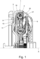
- the Figure 1 shows a torsional vibration damper 1 according to the invention with a primary element 5 and a secondary element 8.
- the primary element 5 and the secondary element 8 can be rotated relative to one another against the force of an energy storage device 4, here a helical compression spring unit 9.
- the helical compression spring unit comprises at least one outer spring 10 and an inner spring 20 provided coaxially to the outer spring, the outer spring 10 being supported radially outward on a spring channel 18.
- the two springs 10, 20 act in parallel.
- the outer spring is designed as an arc spring 11 and the inner spring as a straight helical compression spring 21.
- the arc spring is a helical compression spring that is bent even when removed, i.e. has a radius of curvature.
- the inner spring 20 is designed as a straight helical compression spring, which is cheaper in terms of manufacturing costs than an arc spring.
- the helical compression spring unit 9 is better in the Figure 2 to be seen.
- the straight inner spring 20 in the non-installed state has been inserted into the outer spring 10.
- the inner spring 20 takes on the radius of curvature of the outer spring 10.
- it is crucial that the inner spring 20 is shorter than the outer spring 10. The reason for this is that the outer spring 10 can get caught in the spring channel 18 due to the centrifugal force and the resulting friction force. and the inner spring can come out. This can lead to additional bending stresses and even to the two springs 10, 20 getting caught.
- the inner spring should be made x shorter than the outer spring. It has proven advantageous if the value x is between 1% and 9% of the outer diameter of the outer spring DaA.
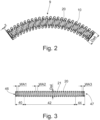
- the individual inner spring 20 is shown as a straight helical compression spring 21. It is clearly visible that the inner spring is divided into a first, a second and a third spring area 40, 42, 44. The first and the third spring area 40, 44 are located at the respective spring ends 46, 47, whereas the second spring area 42 comprises the middle spring area.
- the Figure 3 It is good that a coil spacing WA2 in the second spring region 42 is almost constant, whereas the coil spacing WA1 in the first spring region 40 becomes smaller towards the spring end 46. This is also the case with the coil spacing WA3 in the third spring region 44, which also becomes smaller towards the spring end 47. It is also easy to see here that the outer diameter of the inner spring Dal, measured in the second spring region 42, becomes smaller in the area of the first and third spring regions 40, 44 towards the spring ends 46, 47.
- a helical compression spring unit 9 wherein a spring plate 22, 23 is provided at each end of the helical compression spring unit 9.
- the spring plate 22, 23 comprises a spring plate pin 24, 25, wherein the spring plate pins 24, 25 engage in the inner diameter of the inner spring 20 and guide the inner spring 20 in a radially outward direction. It is assumed that the spring plates 22, 23 in turn extend radially outward on the spring channel 18, particularly well in the Figure 5 to see, support. Further in the Figure 4 The contact area K of the inner spring 20 with the outer spring 10 can be clearly seen, whereby the contact area K is located in the middle area of the helical compression spring unit 9.
- the outer windings of the inner spring 20 come into contact with the inner windings of the outer spring 10, or the inner spring 20 rests in this area K radially outwards on the outer spring 10.
- the outer spring 10 which is designed as a bow spring 11, can be provided with a radius of curvature in the removed state that is smaller than the radius of curvature of the spring channel 18. If the straight inner spring 20 is now inserted into the curved outer spring 10, the radius of curvature of the outer spring 10 will increase due to the inner spring 20. It is advantageous if, after inserting the inner spring 20 into the outer spring 10, the radius of curvature of the coil spring unit 9 corresponds to the radius of curvature of the spring channel 18. This can reduce further stress on the springs 10, 20.
Landscapes
- Engineering & Computer Science (AREA)
- General Engineering & Computer Science (AREA)
- Mechanical Engineering (AREA)
- Physics & Mathematics (AREA)
- Acoustics & Sound (AREA)
- Aviation & Aerospace Engineering (AREA)
- Springs (AREA)
Description
- Die vorliegende Erfindung betrifft einen Drehschwingungsdämpfer für einen Antriebsstrang eines Kraftfahrzeuges. Drehschwingungsdämpfer für einen Antriebsstrang eines Kraftfahrzeuges wie beispielsweise ein Zweimassendämpfer bzw. ein Zweimassenschwungrad (ZMS) sind an sich bekannt. Diese werden beispielsweise in einem Antriebsstrang eines Fahrzeugs verwendet, um hier beispielsweise von einem Motor eingeleitete Drehungleichförmigkeiten, welche zu Drehschwingungen führen können, zu dämpfen. Dabei umfasst der Drehschwingungsdämpfer vorwiegend ein Primärelement sowie ein, gegen einen Energiespeicher verdrehbares Sekundärelement. Dabei wird der Energiespeicher vorwiegend von Schraubendruckfedern gebildet. Dabei ist weiter bekannt, dass die Schraubendruckfedern gerade oder auch gebogen ausgeführt sein können. Auch ist bekannt, dass zwei Schraubendruckfedern parallel geschaltet sind, wobei innerhalb einer Schraubendruckfeder, hier eine Außenfeder, eine weitere Schraubendruckfeder, hier eine Innenfeder, angeordnet ist. Dabei sind beide Schraubendruckfedern auch als Bogenfedern, also vorgebogen, ausgehführt. Dies bedeutet, dass die Schraubendruckfeder in einem nicht montierten Zustand bereits eine gebogene Form vorsieht. Jedoch ist die Herstellung einer Bogenfeder kostenintensiv.
- Ein vergleichbarer Drehschwingungsdämpfer ist mit der
FR 2 775 745 A1 - Es ist daher die Aufgabe der vorliegenden Erfindung einen Drehschwingungsdämpfer vorzusehen, wobei der Drehschwingungsdämpfer zumindest eine Schraubendruckfedereinheit vorsieht, wobei die Schraubendruckfedereinheit zumindest zwei parallel wirkende und koaxial angeordnete Schraubendruckfedern vorsieht, wobei die Schraubendruckfedern in einem verbauten Zustand gebogen sind und wobei die Schraubendruckfedereinheit kostengünstig zu fertigen ist und sicher funktioniert.
- Erfindungsgemäß wird die Aufgabe gelöst durch einen Drehschwingungsdämpfer für einen Antriebsstrang eines Kraftfahrzeuges, umfassend ein um eine Drehachse (A) drehbares Primärelement und ein, gegen einen Energiespeicher relativ zu dem Primärelement verdrehbares Sekundärelement, wobei der Energiespeicher eine Schraubendruckfedereinheit umfasst, wobei die Schraubendruckfedereinheit in einem Federkanal vorgesehen ist und wobei die Schraubendruckfedereinheit eine Außenfeder umfasst, wobei die Außenfeder als eine Bogenfeder ausgeführt ist und wobei innerhalb der Außenfeder und nahezu koaxial zu der Außenfeder eine Innenfeder vorgesehen ist, wobei die Innenfeder in einem aus der Schraubendruckfedereinheit ausgebauten Zustand als eine gerade Schraubendruckfeder ausgeführt ist, wobei die Innenfeder eine Windungsrichtung hat, die entgegengesetzt zu einer Windungsrichtung der Außenfeder ist und wobei die Innenfeder in einem in dem Drehschwingungsdämpfer eingebauten Zustand um einen Wert x kürzer ist, als die Außenfeder, wobei der Wert x kleiner oder gleich Außendurchmesser (DaA) der Außenfeder (10) ist.. Dabei sei hier erwähnt, dass die Bogenfeder eine Schraubendruckfeder ist, die in einem ausgebauten Zustand gebogen ist, also sich entlang eines Krümmungsradius axial erstreckt. Innerhalb dieser Bogenfeder ist eine gerade Schraubendruckfeder als Innenfeder vorgesehen. Dabei ergeben die als Bogenfeder ausgeführte Außenfeder und die als gerade Schraubendruckfeder ausgeführt Innenfeder die Schraubendruckfedereinheit. Dabei ist weiter zu erwähnen, dass eine gerade Schraubendruckfeder kostengünstiger und einfacher herzustellen ist, als eine Bogenfeder. Von daher können durch die Verwendung einer geraden Schraubendruckfeder als Innenfeder Herstellungskosten reduziert werden. Um auch die sichere Funktion der Schraubendruckfedereinheit sicherzustellen sind weitere Merkmale entscheidend. Dabei sei hier erwähnt, dass bei dieser Kombination von einer Bogenfeder als Außenfeder und einer geraden Schraubendruckfeder als Innenfeder die Innenfeder kürzer ausgeführt ist. Dabei ist es vorteilhaft, dass die Innenfeder um einen Wert x kürzer ausgeführt ist, wobei der Wert x der Außendurchmesser der Außenfeder ist oder kleiner. Durch diese Auslegung der Schraubendruckfedereinheit kann eine vorteilhafte Funktionssicherheit erreicht werden. Weiter sein hier erwähnt, dass die entgegengesetzte Windungsrichtung von der Außenfeder zu der Innenfeder dazu vorteilhaft ist, dass die Windungen der Federn sich im Betrieb nicht ineinander verhaken.
- Weiter kann es vorgesehen sein, dass die Innenfeder im ausgebauten Zustand in einer axialer Staffelung zumindest einen ersten Federbereich, einen zweiten Federbereich und einen dritten Federbereich vorsieht, wobei der erste und der dritte Federbereich am jeweiligen Ende der Innenfeder ist und wobei der zweite Federbereich der mittlere Federbereich ist. Dabei sieht der erste Federbereich einen ersten Windungsabstand und der zweite Federbereich einen zweiten Windungsabstand und der dritte Federbereich einen dritten Windungsabstand vor, wobei der erste und der dritte Windungsabstand kürzer ist als der zweite Windungsabstand. Dabei kann weiter ein Verlauf des ersten, des zweiten oder des dritten Windungsabstands für den jeweiligen Federbereich konstant oder progressiv oder degressiv verlaufen.
- Auch kann es sein, dass ein Außendurchmesser des ersten und des dritten Federbereichs der Innenfeder sich zum jeweiligen Federende hin reduziert. Dabei kann durch das sogenannte Einziehen der Federenden und bei einer Verwendung von einem Federteller mit einem Federtellerzapfen für die Innenfeder erreicht werden, dass sich die Innenfeder am Federtellerzapfen mit der jeweils ersten Windung abstützt. Hierdurch kann es vermieden werden, dass die Federenden der Innenfeder in Kontakt zu der Au-ßenfeder kommen. Voraussetzung hierfür ist jedoch, dass sich dann der Federteller am Federkanal abstützt.
- Wie bereits erwähnt können die beiden Federenden der Innenfeder mittels jeweils eines Federtellers radial geführt werden.
- Dennoch wird im Betrieb die Innenfeder zumindest teilweise mit der Außenfeder in Kontakt kommen. Die kann vornehmlich den zweiten Federbereich der Innenfeder betreffen, also den mittleren Bereich, der durch Fliehkraft und/oder auch durch eine Kompression der Innenfeder nach Außen gegen die Innenwindung der Außenfeder gedrückt wird. Dabei können die Innenfeder und die Außenfeder an den Kontaktstellen zueinander reiben. Um hier einen möglichen Verschleiß zu reduzieren kann es vorteilhaft sein, dass die Außenfeder und/oder die Innenfeder durch ein Härteverfahren oberflächenbehandelt sind. Durch die härtere Oberfläche kann an den Kontaktstellen von Innenfeder zu Außenfeder der Verschleiß verringert werden. Dabei kann vorteilhaft ein ein Nitrierverfahren als Härteverfahren verwendet werden.
- Weiter kann es vorgesehen sein, dass zumindest eine der beiden Federendspitzen im eingebauten Zustand sich radial außen befindet oder sich zumindest nahezu radial au-ßen befindet. Dies bedeutet, dass die Innenfeder bei dem Einbau in die Schraubendruckfedereinheit sich in einem ausgerichteten Zustand befindet, bei dem zumindest ein Federende mit der Federendspitze nach radial außen oder nahezu nach radial außen zeigt. In einer vorteilhaften Ausführung ist die Innenfeder so auszuführen, dass beiden Federendspitzen im eingebauten Zustand in die Schraubendruckfedereinheit nach radial außen oder zumindest nahezu nach radial außen zeigen. Hierdurch haben Versuche bestätigt, dass die Haltbarkeit der Innenfeder, speziell an den Federenden, verbessert werden kann. Dabei ist darauf zu achten, dass auch im Betrieb die Federendspitzen nach außen oder nahezu nach außen zeigen und sich die Innenfeder im Betrieb nicht um ihre Längsachse verdreht. Diese Sicherung kann vorteilhaft mit den voran bereits beschriebenen Federteller gewährleistet werden, indem die Federenden auf die Federtellerzapfen nahezu spielfrei aufgenommen sind.
- Weiter kann es vorgesehen sein, dass die Schraubendruckfedereinheit, bestehend aus zumindest der Außenfeder und der Innenfeder, im ausgebauten Zustand einen Krümmungsradius hat, der nahezu gleich oder gleich einem Krümmungsradius des Federkanals ist. Dies ist vorteilhaft, da dann die Schraubendruckfedereinheit im eingebauten Zustand ebenfalls nahezu den Krümmungsradius vorsieht, den auch der Federkanal aufweist. Hierdurch können zusätzliche Spannungen an der Schraubendruckfedereinheit reduziert werden.
- Dabei kann weiterhin ein Abstand zwischen dem Außendurchmesser der Innenfeder und dem Innendurchmesser der Außenfeder zwischen 1 % und 9% des Außendurchmessers der Außenfeder betragen. Dies bedeutet, dass ein Spiel in radialer Richtung zwischen der Innenfeder und der Außenfeder vorteilhaft 1% bis 9% des Außendurchmessers der Außenfeder ist.
- Nachfolgend wird die Erfindung beispielhaft beschrieben. Dabei zeigt die
- Fig. 1
- einen erfindungsgemäßen Drehschwingungsdämpfer.
- Fig. 2
- eine Schraubendruckfedereinheit.
- Fig. 3
- eine gerade Innenfeder.
- Fig. 4
- eine Schraubendruckfedereinheit mit Federteller
- Fig. 5
- eine Schraubendruckfedereinheit mit Federteller
- Die
Figur 1 zeigt einen erfindungsgemäßen Drehschwingungsdämpfer 1 mit einem Primärlement 5 und einem Sekundärelement 8. Dabei sind das Primärelement 5 und das Sekundärelement 8 gegen die Kraft eines Energiespeichers 4, hier eine Schraubendruckfedereinheit 9 relativ zueinander verdrehbar. Dabei umfasst die Schraubendruckfedereinheit zumindest eine Außenfeder 10 und eine koaxial zu der Außenfeder vorgesehene Innenfeder 20, wobei sich die Außenfeder 10 nach radial außen an einem Federkanal 18 abstützt. Dabei wirken die beiden Federn 10, 20 parallel. Dabei ist hier die Außenfeder als eine Bogenfeder 11 ausgeführt und die Innenfeder als eine gerade Schraubendruckfeder 21. Der Vollständigkeit halber sei hier erwähnt, dass es sich bei der Bogenfeder um eine Schraubendruckfeder handelt, die auch in einem ausgebauten Zustand gebogen ist, also einen Krümmungsradius aufweist. Hingegen ist die Innenfeder 20 als gerade Schraubendruckfeder ausgeführt, was von den Herstellungskosten günstiger ist, als eine Bogenfeder. - Dabei ist die Schraubendruckfedereinheit 9 besser in der
Figur 2 zu sehen. Hier wurde die im nicht verbauten Zustand gerade Innenfeder 20 in die Außenfeder 10 eingesetzt. Hierdurch nimmt die Innenfeder 20 den Krümmungsradius der Außenfeder 10 an. Für die sichere Funktion ist dabei entscheidend, dass die Innenfeder 20 dabei kürzer ist als die Außenfeder 10. Der Grund liegt darin, dass die Außenfeder 10 in dem Federkanal 18 bedingt durch die Fliehkraft und die dadurch entstehende Reibkraft hängen bleiben kann und die Innenfeder austritt. Hierdurch kann es zu zusätzlichen Biegebelastungen und sogar zu einem Verhaken der beiden Federn 10, 20 kommen. Durch eine zu der Auenfeder 10 verkürzte Innenfeder 20 kann dieser Effekt des Austretens bzw. des Verhakens verringert werden, was sich auch vorteilhaft auf die Funktionsfähigkeit und die Lebensdauer auswirken kann. Dabei ist die Innenfeder um einen Wert x kürzer auszuführen, als die Außenfeder. Dabei hat es sich vorteilhaft herausgestellt, wenn der Wert x zwischen 1 % und 9 % des Außendurchmessers der Außenfeder DaA ist. - In der
Figur 3 wird die einzelne Innenfeder 20, als gerade Schraubendruckfeder 21 dargestellt. Hierbei ist gut zu erkennen, dass die Innenfeder sich in einen ersten, einen zweiten und in einen dritten Federbereich 40, 42, 44 unterteilt. Dabei befinden sich der erste und der dritte Federbereich 40, 44 an den jeweiligen Federenden 46, 47 wohingegen der zweite Federbereich 42 den mittleren Federbereich umfasst. Dabei zeigt dieFigur 3 gut, dass ein Windungsabstand WA2 im zweiten Federbereich 42 nahezu konstant verläuft, wohingegen der Windungsabstand WA1 am ersten Federbereich 40 zu Federende 46 hin geringer wird. Dies ist ebenso mit dem Windungsabstand WA3 am dritten Federbereich 44, der ebenfalls zum Federende 47 hin geringer wird. Ebenso ist hier gut zu erkennen, dass der Außendurchmesser der Innenfeder Dal, gemessen im zweiten Federbereich 42, im Bereich des ersten und des dritten Federbereichs 40, 44 zu den Federenden 46, 47 hin geringer wird. - In der
Figur 4 und derFigur 5 sind eine Schraubendruckfedereinheit 9 gezeigt, wobei an den jeweiligen Enden der Schraubendruckfedereinheit 9 jeweils ein Federteller 22, 23 vorgesehen ist. Dabei umfasst jeweils der Federteller 22, 23, einen Federtellerzapfen 24, 25, wobei die Federtellerzapfen 24, 25 in den Innendurchmesser der Innenfeder 20 eingreifen und die Innenfeder 20 in Richtung nach radial außen führen. Dabei wird vorausgesetzt, dass die Federteller 22, 23 sich wiederum nach radial außen an dem Federkanal 18, besonders gut in derFigur 5 zu sehen, abstützen. Weiter ist in derFigur 4 gut der Kontaktbereich K der Innenfeder 20 mit der Außenfeder 10 zu erkennen, wobei sich der Kontaktbereich K im mittleren Bereich der Schraubendruckfedereinheit 9 befindet. Hierbei kommen die Außenwindungen der Innenfeder 20 mit den Innenwindungen der Außenfeder 10 in Kontakt, bzw. die Innenfeder 20 stützt sich in diesem Bereich K nach radial außen an der Außenfeder 10 ab. Für den Fall, dass keine Federteller verwendet werden sei hier weiter angemerkt, dass die Außenfeder 10, die ja als Bogenfeder 11 ausgeführt ist, im ausgebauten Zustand mit einem Krümmungsradius versehen sein kann, der geringer ist als der Krümmungsradius des Federkanals 18. Wird nun die gerade Innenfeder 20 in die gekrümmte Außenfeder 10 eingeführt, so wird sich der Krümmungsradius der Außenfeder 10 durch die Innenfeder 20 vergrößern. Dabei ist es vorteilhaft, wenn nach dem Einsetzten der Innenfeder 20 in die Außenfeder 10 der Krümmungsradius der Schraubenfedereinheit 9 dem Krümmungsradius des Federkanals 18 entspricht. Hierdurch können weitere Spannungen an den Federn 10, 20 verringert werden. - Auch ist in der
Figur 4 gut zu erkennen, dass die jeweiligen Federendspitzen 31, 32, nach radial außen gerichtet sind. Hierdurch können weiter Spannungen in der Innenfeder 20, vor allem im Betrieb, verringert werden. -
- 1
- Drehschwingungsdämpfer
- 4
- Energiespeicher
- 5
- Primärelement
- 8
- Sekundärelement
- 9
- Schraubendruckfedereinheit
- 10
- Außenfeder
- 11
- Bogenfeder
- 18
- Federkanal
- 20
- Innenfeder
- 21
- Schraubendruckfeder
- 22
- Federteller
- 23
- Federteller
- 24
- Federtellerzapfen
- 25
- Federtellerzapfen
- 31
- Federendspitzen
- 32
- Federendspitzen
- 40
- erster Federbereich
- 42
- zweiter Federbereich
- 44
- dritter Federbereich
- 46
- Federende
- 47
- Federende
- 50
- Kontaktstelle
- WA1
- erster Windungsabstand
- WA2
- zweiter Windungsabstand
- WA3
- dritter Windungsabstand
- Dal
- Außendurchmesser Innenfeder
- DaA
- Außendurchmesser Außenfeder
- K
- Kontaktbereich
Claims (11)
- Drehschwingungsdämpfer für einen Antriebsstrang eines Kraftfahrzeuges, umfassend ein um eine Drehachse (A) drehbares Primärelement (5) und ein, gegen einen Energiespeicher (4) relativ zu dem Primärelement (5) verdrehbares Sekundärelement (8), wobei der Energiespeicher (4) eine Schraubendruckfedereinheit (9) umfasst, wobei die Schraubendruckfedereinheit (9) in einem Federkanal (18) vorgesehen ist und wobei die Schraubendruckfedereinheit (9) eine Außenfeder (10) umfasst, wobei die Außenfeder (10) als eine Bogenfeder (11) ausgeführt ist und wobei innerhalb der Außenfeder (10) und nahezu koaxial zu der Außenfeder (10) eine Innenfeder (20) vorgesehen ist, wobei die Innenfeder (20) in einem aus der Schraubendruckfedereinheit (9) ausgebauten Zustand als eine gerade Schraubendruckfeder (21) ausgeführt ist, wobei die Innenfeder (20) eine Windungsrichtung hat, die entgegengesetzt zu einer Windungsrichtung der Außenfeder (10) ist und wobei die Innenfeder (20) in einem in dem Drehschwingungsdämpfer eingebauten Zustand um einen Wert x kürzer ist, als die Außenfeder (10), dadurch gekennzeichnet, dass der Wert x kleiner oder gleich Außendurchmesser (DaA) der Außenfeder (10) ist.
- Drehschwingungsdämpfer (1) nach Anspruch 1, dadurch gekennzeichnet, dass die Innenfeder (20) im ausgebauten Zustand in einer axialer Staffelung zumindest einen ersten Federbereich (40), einen zweiten Federbereich (42) und einen dritten Federbereich (44) vorsieht, wobei der erste und der dritte Federbereich (40, 44) am jeweiligen Ende der Innenfeder (20) ist und wobei der zweite Federbereich (42) der mittlere Federbereich ist.
- Drehschwingungsdämpfer (1) nach Anspruch 2, dadurch gekennzeichnet, dass der erste Federbereich (40) einen ersten Windungsabstand (WA1) vorsieht und dass der zweite Federbereich (42) einen zweiten Windungsabstand (WA2) vorsieht und dass der dritte Federbereich (44) einen dritten Windungsabstand (WA3) vorsieht, wobei der erste und der dritte Windungsabstand (WA1; WA3) kürzer ist als der zweite Windungsabstand (WA2).
- Drehschwingungsdämpfer (1) nach Anspruch 3, dadurch gekennzeichnet, dass ein Verlauf des ersten, des zweiten oder des dritten Windungsabstands (WA1, WA2, WA3) für den jeweiligen Federbereich (40, 42, 44) konstant oder progressiv oder degressiv ist.
- Drehschwingungsdämpfer (1) nach Anspruch 3 oder 4, dadurch gekennzeichnet, dass ein Außendurchmesser (Dal) des ersten und des dritten Federbereichs (FB1, FB3) der Innenfeder (20) sich zum jeweiligen Federende (46, 47) hin reduziert.
- Drehschwingungsdämpfer (1) nach einem der Ansprüche 1 bis 5, dadurch gekennzeichnet, dass die beiden Federenden der Innenfeder (20) mittels jeweils eines Federtellers (22; 23) radial geführt werden.
- Drehschwingungsdämpfer (1) nach einem der Ansprüche 1 bis 6, dadurch gekennzeichnet, dass die Außenfeder (10) und/oder die Innenfeder (20) durch ein Härteverfahren oberflächenbehandelt sind.
- Drehschwingungsdämpfer (1) nach Anspruch 7, dadurch gekennzeichnet, dass das Härteverfahren ein Nitrierverfahren ist.
- Drehschwingungsdämpfer (1) nach einem der Ansprüche 1 bis 8, dadurch gekennzeichnet, dass zumindest eine der beiden Federendspitzen (31, 32) im eingebauten Zustand sich radial außen befindet oder sich zumindest nahezu radial außen befindet.
- Drehschwingungsdämpfer (1) nach einem der Ansprüche 1 bis 9, dadurch gekennzeichnet, dass die Schraubendruckfedereinheit (9), bestehend aus zumindest der Au-ßenfeder (10) und der Innenfeder (20), im ausgebauten Zustand einen Krümmungsradius hat, der nahezu gleich oder gleich einem Krümmungsradius des Federkanals (8) ist.
- Drehschwingungsdämpfer (1) nach einem der Ansprüche 1 bis 10, dadurch gekennzeichnet, dass ein Abstand zwischen dem Außendurchmesser der Innenfeder (Dal) und dem Innendurchmesser der Außenfeder (10) zwischen 1% und 9% des Außendurchmessers der Außenfeder (DaA) beträgt.
Applications Claiming Priority (3)
| Application Number | Priority Date | Filing Date | Title |
|---|---|---|---|
| DE102019202296 | 2019-02-20 | ||
| DE102020201916.9A DE102020201916A1 (de) | 2019-02-20 | 2020-02-17 | Drehschwingungsdämpfer |
| PCT/EP2020/054274 WO2020169625A1 (de) | 2019-02-20 | 2020-02-19 | Drehschwingungsdämpfer mit einer schraubenfederanordnung |
Publications (2)
| Publication Number | Publication Date |
|---|---|
| EP3927995A1 EP3927995A1 (de) | 2021-12-29 |
| EP3927995B1 true EP3927995B1 (de) | 2024-07-31 |
Family
ID=71844028
Family Applications (1)
| Application Number | Title | Priority Date | Filing Date |
|---|---|---|---|
| EP20706676.2A Active EP3927995B1 (de) | 2019-02-20 | 2020-02-19 | Drehschwingungsdämpfer mit einer schraubenfederanordnung |
Country Status (4)
| Country | Link |
|---|---|
| US (1) | US20220252132A1 (de) |
| EP (1) | EP3927995B1 (de) |
| DE (1) | DE102020201916A1 (de) |
| WO (1) | WO2020169625A1 (de) |
Citations (2)
| Publication number | Priority date | Publication date | Assignee | Title |
|---|---|---|---|---|
| FR2790808B1 (fr) * | 1999-03-10 | 2006-06-09 | Luk Lamellen & Kupplungsbau | Amortisseur de vibrations |
| DE102011109262A1 (de) * | 2011-08-03 | 2013-02-07 | Borgwarner Inc. | Schraubenfederanordnung für einen Torsionsschwingungsdämpfer |
Family Cites Families (6)
| Publication number | Priority date | Publication date | Assignee | Title |
|---|---|---|---|---|
| FR2706006B1 (fr) * | 1993-06-02 | 1995-07-07 | Valeo | Volant amortisseur notamment pour véhicule automobile. |
| FR2714949B1 (fr) * | 1993-11-15 | 1996-03-08 | Valeo | Volant amortisseur notamment pour véhicule automobile. |
| DE19909044B4 (de) * | 1998-03-07 | 2018-06-21 | Schaeffler Technologies AG & Co. KG | Drehschwingungsdämpfer |
| FR2902165B1 (fr) * | 2006-06-08 | 2008-07-25 | Valeo Embrayages | Double volant amortisseur, en particulier pour vehicule automobile |
| DE102014215138A1 (de) * | 2013-08-14 | 2015-02-19 | Schaeffler Technologies Gmbh & Co. Kg | Endkappe sowie Torsionsschwingungsdämpfer mit solch einer Endkappe |
| JP6998648B2 (ja) * | 2016-03-25 | 2022-01-18 | 株式会社エクセディ | スプリング組立体及びそれを備えたトルクコンバータのロックアップ装置 |
-
2020
- 2020-02-17 DE DE102020201916.9A patent/DE102020201916A1/de not_active Withdrawn
- 2020-02-19 US US17/432,268 patent/US20220252132A1/en not_active Abandoned
- 2020-02-19 EP EP20706676.2A patent/EP3927995B1/de active Active
- 2020-02-19 WO PCT/EP2020/054274 patent/WO2020169625A1/de not_active Ceased
Patent Citations (2)
| Publication number | Priority date | Publication date | Assignee | Title |
|---|---|---|---|---|
| FR2790808B1 (fr) * | 1999-03-10 | 2006-06-09 | Luk Lamellen & Kupplungsbau | Amortisseur de vibrations |
| DE102011109262A1 (de) * | 2011-08-03 | 2013-02-07 | Borgwarner Inc. | Schraubenfederanordnung für einen Torsionsschwingungsdämpfer |
Also Published As
| Publication number | Publication date |
|---|---|
| EP3927995A1 (de) | 2021-12-29 |
| WO2020169625A1 (de) | 2020-08-27 |
| US20220252132A1 (en) | 2022-08-11 |
| DE102020201916A1 (de) | 2020-08-20 |
Similar Documents
| Publication | Publication Date | Title |
|---|---|---|
| DE19734322B4 (de) | Torsionsschwingungsdämpfer mit Wälzkörpern als Koppelelemente | |
| DE102008047596A1 (de) | Elastischer Gelenkkörper | |
| EP3026293B2 (de) | Federpaket | |
| DE202015006181U1 (de) | Drehschwingungsdämpfungsanordnung, insbesondere Tilgerbaugruppe | |
| DE102008050202A1 (de) | Elastischer Gelenkkörper | |
| DE4028616C2 (de) | Kupplungsscheibe mit identischen Führungsteilen zur Ansteuerung der Schraubenfedern für den Leerlaufbereich | |
| DE102013224531A1 (de) | Bogen-schraubenfederauslegung | |
| DE102009013367A1 (de) | Kupplungsanordnung | |
| DE102009022440B4 (de) | Drehschwingungsdämpfer mit mindestens einer Federeinrichtung aus zwei Schraubenfedern | |
| DE102008045909A1 (de) | Drehschwingungsdämpfer | |
| EP0472950B1 (de) | Elastische Kupplung | |
| DE102018129258A1 (de) | Kupplungsanordnung und Hybridmodul | |
| DE102009022289A1 (de) | Drehschwingungsdämpfer | |
| DE102020201916A1 (de) | Drehschwingungsdämpfer | |
| DE102018219568A1 (de) | Drehschwingungsdämpfungsanordnung | |
| EP3321538A1 (de) | Torsionsschwingungsdämpfer | |
| DE102009038266A1 (de) | Feder-Dämpfer-System | |
| DE102006052853A1 (de) | Torsionsschwingungsdämpferanordnung | |
| DE9017936U1 (de) | Elastische Kupplung | |
| DE102022118527B4 (de) | Fliehkraftpendel mit optimierter Nietverbindung | |
| DE19849623B4 (de) | Reibungskupplung | |
| DE102012210406A1 (de) | Drehschwingungsdämpfer | |
| DE102022131206B4 (de) | Torsionsschwingungsdämpfer mit einem Federsystem | |
| DE102013226137A1 (de) | Spiralfederwicklung mit partiell unterschiedlichen Wicklungsabständen zur lokalen Eliminierung des Windungskontaktes der einzelnen Wicklungen | |
| EP2691668B1 (de) | Nachstelleinrichtung eines kopplungsaggregats |
Legal Events
| Date | Code | Title | Description |
|---|---|---|---|
| STAA | Information on the status of an ep patent application or granted ep patent |
Free format text: STATUS: UNKNOWN |
|
| STAA | Information on the status of an ep patent application or granted ep patent |
Free format text: STATUS: THE INTERNATIONAL PUBLICATION HAS BEEN MADE |
|
| PUAI | Public reference made under article 153(3) epc to a published international application that has entered the european phase |
Free format text: ORIGINAL CODE: 0009012 |
|
| STAA | Information on the status of an ep patent application or granted ep patent |
Free format text: STATUS: REQUEST FOR EXAMINATION WAS MADE |
|
| 17P | Request for examination filed |
Effective date: 20210823 |
|
| AK | Designated contracting states |
Kind code of ref document: A1 Designated state(s): AL AT BE BG CH CY CZ DE DK EE ES FI FR GB GR HR HU IE IS IT LI LT LU LV MC MK MT NL NO PL PT RO RS SE SI SK SM TR |
|
| DAV | Request for validation of the european patent (deleted) | ||
| DAX | Request for extension of the european patent (deleted) | ||
| REG | Reference to a national code |
Ref country code: DE Ref legal event code: R079 Free format text: PREVIOUS MAIN CLASS: F16F0015123000 Ipc: F16F0001040000 Ref country code: DE Ref legal event code: R079 Ref document number: 502020008728 Country of ref document: DE Free format text: PREVIOUS MAIN CLASS: F16F0015123000 Ipc: F16F0001040000 |
|
| RIC1 | Information provided on ipc code assigned before grant |
Ipc: F16F 15/123 20060101ALI20240205BHEP Ipc: F16F 3/04 20060101ALI20240205BHEP Ipc: F16F 1/04 20060101AFI20240205BHEP |
|
| GRAP | Despatch of communication of intention to grant a patent |
Free format text: ORIGINAL CODE: EPIDOSNIGR1 |
|
| STAA | Information on the status of an ep patent application or granted ep patent |
Free format text: STATUS: GRANT OF PATENT IS INTENDED |
|
| INTG | Intention to grant announced |
Effective date: 20240326 |
|
| GRAS | Grant fee paid |
Free format text: ORIGINAL CODE: EPIDOSNIGR3 |
|
| GRAA | (expected) grant |
Free format text: ORIGINAL CODE: 0009210 |
|
| STAA | Information on the status of an ep patent application or granted ep patent |
Free format text: STATUS: THE PATENT HAS BEEN GRANTED |
|
| AK | Designated contracting states |
Kind code of ref document: B1 Designated state(s): AL AT BE BG CH CY CZ DE DK EE ES FI FR GB GR HR HU IE IS IT LI LT LU LV MC MK MT NL NO PL PT RO RS SE SI SK SM TR |
|
| REG | Reference to a national code |
Ref country code: CH Ref legal event code: EP Ref country code: GB Ref legal event code: FG4D Free format text: NOT ENGLISH |
|
| REG | Reference to a national code |
Ref country code: DE Ref legal event code: R096 Ref document number: 502020008728 Country of ref document: DE |
|
| REG | Reference to a national code |
Ref country code: IE Ref legal event code: FG4D Free format text: LANGUAGE OF EP DOCUMENT: GERMAN |
|
| REG | Reference to a national code |
Ref country code: LT Ref legal event code: MG9D |
|
| REG | Reference to a national code |
Ref country code: NL Ref legal event code: MP Effective date: 20240731 |
|
| PG25 | Lapsed in a contracting state [announced via postgrant information from national office to epo] |
Ref country code: PT Free format text: LAPSE BECAUSE OF FAILURE TO SUBMIT A TRANSLATION OF THE DESCRIPTION OR TO PAY THE FEE WITHIN THE PRESCRIBED TIME-LIMIT Effective date: 20241202 |
|
| PG25 | Lapsed in a contracting state [announced via postgrant information from national office to epo] |
Ref country code: PT Free format text: LAPSE BECAUSE OF FAILURE TO SUBMIT A TRANSLATION OF THE DESCRIPTION OR TO PAY THE FEE WITHIN THE PRESCRIBED TIME-LIMIT Effective date: 20241202 |
|
| PG25 | Lapsed in a contracting state [announced via postgrant information from national office to epo] |
Ref country code: NO Free format text: LAPSE BECAUSE OF FAILURE TO SUBMIT A TRANSLATION OF THE DESCRIPTION OR TO PAY THE FEE WITHIN THE PRESCRIBED TIME-LIMIT Effective date: 20241031 |
|
| PG25 | Lapsed in a contracting state [announced via postgrant information from national office to epo] |
Ref country code: NL Free format text: LAPSE BECAUSE OF FAILURE TO SUBMIT A TRANSLATION OF THE DESCRIPTION OR TO PAY THE FEE WITHIN THE PRESCRIBED TIME-LIMIT Effective date: 20240731 Ref country code: PL Free format text: LAPSE BECAUSE OF FAILURE TO SUBMIT A TRANSLATION OF THE DESCRIPTION OR TO PAY THE FEE WITHIN THE PRESCRIBED TIME-LIMIT Effective date: 20240731 Ref country code: GR Free format text: LAPSE BECAUSE OF FAILURE TO SUBMIT A TRANSLATION OF THE DESCRIPTION OR TO PAY THE FEE WITHIN THE PRESCRIBED TIME-LIMIT Effective date: 20241101 Ref country code: FI Free format text: LAPSE BECAUSE OF FAILURE TO SUBMIT A TRANSLATION OF THE DESCRIPTION OR TO PAY THE FEE WITHIN THE PRESCRIBED TIME-LIMIT Effective date: 20240731 |
|
| PG25 | Lapsed in a contracting state [announced via postgrant information from national office to epo] |
Ref country code: BG Free format text: LAPSE BECAUSE OF FAILURE TO SUBMIT A TRANSLATION OF THE DESCRIPTION OR TO PAY THE FEE WITHIN THE PRESCRIBED TIME-LIMIT Effective date: 20240731 |
|
| PG25 | Lapsed in a contracting state [announced via postgrant information from national office to epo] |
Ref country code: LV Free format text: LAPSE BECAUSE OF FAILURE TO SUBMIT A TRANSLATION OF THE DESCRIPTION OR TO PAY THE FEE WITHIN THE PRESCRIBED TIME-LIMIT Effective date: 20240731 |
|
| PG25 | Lapsed in a contracting state [announced via postgrant information from national office to epo] |
Ref country code: IS Free format text: LAPSE BECAUSE OF FAILURE TO SUBMIT A TRANSLATION OF THE DESCRIPTION OR TO PAY THE FEE WITHIN THE PRESCRIBED TIME-LIMIT Effective date: 20241130 |
|
| PG25 | Lapsed in a contracting state [announced via postgrant information from national office to epo] |
Ref country code: HR Free format text: LAPSE BECAUSE OF FAILURE TO SUBMIT A TRANSLATION OF THE DESCRIPTION OR TO PAY THE FEE WITHIN THE PRESCRIBED TIME-LIMIT Effective date: 20240731 |
|
| PG25 | Lapsed in a contracting state [announced via postgrant information from national office to epo] |
Ref country code: RS Free format text: LAPSE BECAUSE OF FAILURE TO SUBMIT A TRANSLATION OF THE DESCRIPTION OR TO PAY THE FEE WITHIN THE PRESCRIBED TIME-LIMIT Effective date: 20241031 Ref country code: ES Free format text: LAPSE BECAUSE OF FAILURE TO SUBMIT A TRANSLATION OF THE DESCRIPTION OR TO PAY THE FEE WITHIN THE PRESCRIBED TIME-LIMIT Effective date: 20240731 |
|
| PG25 | Lapsed in a contracting state [announced via postgrant information from national office to epo] |
Ref country code: RS Free format text: LAPSE BECAUSE OF FAILURE TO SUBMIT A TRANSLATION OF THE DESCRIPTION OR TO PAY THE FEE WITHIN THE PRESCRIBED TIME-LIMIT Effective date: 20241031 Ref country code: PL Free format text: LAPSE BECAUSE OF FAILURE TO SUBMIT A TRANSLATION OF THE DESCRIPTION OR TO PAY THE FEE WITHIN THE PRESCRIBED TIME-LIMIT Effective date: 20240731 Ref country code: NO Free format text: LAPSE BECAUSE OF FAILURE TO SUBMIT A TRANSLATION OF THE DESCRIPTION OR TO PAY THE FEE WITHIN THE PRESCRIBED TIME-LIMIT Effective date: 20241031 Ref country code: NL Free format text: LAPSE BECAUSE OF FAILURE TO SUBMIT A TRANSLATION OF THE DESCRIPTION OR TO PAY THE FEE WITHIN THE PRESCRIBED TIME-LIMIT Effective date: 20240731 Ref country code: LV Free format text: LAPSE BECAUSE OF FAILURE TO SUBMIT A TRANSLATION OF THE DESCRIPTION OR TO PAY THE FEE WITHIN THE PRESCRIBED TIME-LIMIT Effective date: 20240731 Ref country code: IS Free format text: LAPSE BECAUSE OF FAILURE TO SUBMIT A TRANSLATION OF THE DESCRIPTION OR TO PAY THE FEE WITHIN THE PRESCRIBED TIME-LIMIT Effective date: 20241130 Ref country code: HR Free format text: LAPSE BECAUSE OF FAILURE TO SUBMIT A TRANSLATION OF THE DESCRIPTION OR TO PAY THE FEE WITHIN THE PRESCRIBED TIME-LIMIT Effective date: 20240731 Ref country code: GR Free format text: LAPSE BECAUSE OF FAILURE TO SUBMIT A TRANSLATION OF THE DESCRIPTION OR TO PAY THE FEE WITHIN THE PRESCRIBED TIME-LIMIT Effective date: 20241101 Ref country code: FI Free format text: LAPSE BECAUSE OF FAILURE TO SUBMIT A TRANSLATION OF THE DESCRIPTION OR TO PAY THE FEE WITHIN THE PRESCRIBED TIME-LIMIT Effective date: 20240731 Ref country code: ES Free format text: LAPSE BECAUSE OF FAILURE TO SUBMIT A TRANSLATION OF THE DESCRIPTION OR TO PAY THE FEE WITHIN THE PRESCRIBED TIME-LIMIT Effective date: 20240731 Ref country code: BG Free format text: LAPSE BECAUSE OF FAILURE TO SUBMIT A TRANSLATION OF THE DESCRIPTION OR TO PAY THE FEE WITHIN THE PRESCRIBED TIME-LIMIT Effective date: 20240731 |
|
| PG25 | Lapsed in a contracting state [announced via postgrant information from national office to epo] |
Ref country code: RO Free format text: LAPSE BECAUSE OF FAILURE TO SUBMIT A TRANSLATION OF THE DESCRIPTION OR TO PAY THE FEE WITHIN THE PRESCRIBED TIME-LIMIT Effective date: 20240731 Ref country code: DK Free format text: LAPSE BECAUSE OF FAILURE TO SUBMIT A TRANSLATION OF THE DESCRIPTION OR TO PAY THE FEE WITHIN THE PRESCRIBED TIME-LIMIT Effective date: 20240731 Ref country code: SM Free format text: LAPSE BECAUSE OF FAILURE TO SUBMIT A TRANSLATION OF THE DESCRIPTION OR TO PAY THE FEE WITHIN THE PRESCRIBED TIME-LIMIT Effective date: 20240731 |
|
| PG25 | Lapsed in a contracting state [announced via postgrant information from national office to epo] |
Ref country code: EE Free format text: LAPSE BECAUSE OF FAILURE TO SUBMIT A TRANSLATION OF THE DESCRIPTION OR TO PAY THE FEE WITHIN THE PRESCRIBED TIME-LIMIT Effective date: 20240731 |
|
| PG25 | Lapsed in a contracting state [announced via postgrant information from national office to epo] |
Ref country code: CZ Free format text: LAPSE BECAUSE OF FAILURE TO SUBMIT A TRANSLATION OF THE DESCRIPTION OR TO PAY THE FEE WITHIN THE PRESCRIBED TIME-LIMIT Effective date: 20240731 |
|
| PG25 | Lapsed in a contracting state [announced via postgrant information from national office to epo] |
Ref country code: IT Free format text: LAPSE BECAUSE OF FAILURE TO SUBMIT A TRANSLATION OF THE DESCRIPTION OR TO PAY THE FEE WITHIN THE PRESCRIBED TIME-LIMIT Effective date: 20240731 Ref country code: SK Free format text: LAPSE BECAUSE OF FAILURE TO SUBMIT A TRANSLATION OF THE DESCRIPTION OR TO PAY THE FEE WITHIN THE PRESCRIBED TIME-LIMIT Effective date: 20240731 |
|
| REG | Reference to a national code |
Ref country code: DE Ref legal event code: R097 Ref document number: 502020008728 Country of ref document: DE |
|
| PLBE | No opposition filed within time limit |
Free format text: ORIGINAL CODE: 0009261 |
|
| STAA | Information on the status of an ep patent application or granted ep patent |
Free format text: STATUS: NO OPPOSITION FILED WITHIN TIME LIMIT |
|
| 26N | No opposition filed |
Effective date: 20250501 |
|
| PG25 | Lapsed in a contracting state [announced via postgrant information from national office to epo] |
Ref country code: SE Free format text: LAPSE BECAUSE OF FAILURE TO SUBMIT A TRANSLATION OF THE DESCRIPTION OR TO PAY THE FEE WITHIN THE PRESCRIBED TIME-LIMIT Effective date: 20240731 |
|
| PG25 | Lapsed in a contracting state [announced via postgrant information from national office to epo] |
Ref country code: MC Free format text: LAPSE BECAUSE OF FAILURE TO SUBMIT A TRANSLATION OF THE DESCRIPTION OR TO PAY THE FEE WITHIN THE PRESCRIBED TIME-LIMIT Effective date: 20240731 |
|
| REG | Reference to a national code |
Ref country code: CH Ref legal event code: PL |
|
| PG25 | Lapsed in a contracting state [announced via postgrant information from national office to epo] |
Ref country code: LU Free format text: LAPSE BECAUSE OF NON-PAYMENT OF DUE FEES Effective date: 20250219 |
|
| PG25 | Lapsed in a contracting state [announced via postgrant information from national office to epo] |
Ref country code: CH Free format text: LAPSE BECAUSE OF NON-PAYMENT OF DUE FEES Effective date: 20250228 |
|
| GBPC | Gb: european patent ceased through non-payment of renewal fee |
Effective date: 20250219 |
|
| REG | Reference to a national code |
Ref country code: BE Ref legal event code: MM Effective date: 20250228 |
|
| PG25 | Lapsed in a contracting state [announced via postgrant information from national office to epo] |
Ref country code: GB Free format text: LAPSE BECAUSE OF NON-PAYMENT OF DUE FEES Effective date: 20250219 |
|
| PG25 | Lapsed in a contracting state [announced via postgrant information from national office to epo] |
Ref country code: FR Free format text: LAPSE BECAUSE OF NON-PAYMENT OF DUE FEES Effective date: 20250228 |
|
| PG25 | Lapsed in a contracting state [announced via postgrant information from national office to epo] |
Ref country code: BE Free format text: LAPSE BECAUSE OF NON-PAYMENT OF DUE FEES Effective date: 20250228 |
|
| PG25 | Lapsed in a contracting state [announced via postgrant information from national office to epo] |
Ref country code: IE Free format text: LAPSE BECAUSE OF NON-PAYMENT OF DUE FEES Effective date: 20250219 |
|
| PGFP | Annual fee paid to national office [announced via postgrant information from national office to epo] |
Ref country code: DE Payment date: 20251224 Year of fee payment: 7 |
|
| PG25 | Lapsed in a contracting state [announced via postgrant information from national office to epo] |
Ref country code: AT Free format text: LAPSE BECAUSE OF NON-PAYMENT OF DUE FEES Effective date: 20250219 |
|
| REG | Reference to a national code |
Ref country code: AT Ref legal event code: MM01 Ref document number: 1708711 Country of ref document: AT Kind code of ref document: T Effective date: 20250219 |