EP3922377B1 - Wickelmaschine, verfahren zur herstellung einer schraubenfeder und schraubenfeder - Google Patents
Wickelmaschine, verfahren zur herstellung einer schraubenfeder und schraubenfeder Download PDFInfo
- Publication number
- EP3922377B1 EP3922377B1 EP19914558.2A EP19914558A EP3922377B1 EP 3922377 B1 EP3922377 B1 EP 3922377B1 EP 19914558 A EP19914558 A EP 19914558A EP 3922377 B1 EP3922377 B1 EP 3922377B1
- Authority
- EP
- European Patent Office
- Prior art keywords
- wire
- laser light
- cutter
- coil spring
- irradiation
- Prior art date
- Legal status (The legal status is an assumption and is not a legal conclusion. Google has not performed a legal analysis and makes no representation as to the accuracy of the status listed.)
- Active
Links
Images


Classifications
-
- B—PERFORMING OPERATIONS; TRANSPORTING
- B23—MACHINE TOOLS; METAL-WORKING NOT OTHERWISE PROVIDED FOR
- B23K—SOLDERING OR UNSOLDERING; WELDING; CLADDING OR PLATING BY SOLDERING OR WELDING; CUTTING BY APPLYING HEAT LOCALLY, e.g. FLAME CUTTING; WORKING BY LASER BEAM
- B23K26/00—Working by laser beam, e.g. welding, cutting or boring
- B23K26/352—Working by laser beam, e.g. welding, cutting or boring for surface treatment
- B23K26/354—Working by laser beam, e.g. welding, cutting or boring for surface treatment by melting
-
- B—PERFORMING OPERATIONS; TRANSPORTING
- B21—MECHANICAL METAL-WORKING WITHOUT ESSENTIALLY REMOVING MATERIAL; PUNCHING METAL
- B21F—WORKING OR PROCESSING OF METAL WIRE
- B21F11/00—Cutting wire
- B21F11/005—Cutting wire springs
-
- B—PERFORMING OPERATIONS; TRANSPORTING
- B21—MECHANICAL METAL-WORKING WITHOUT ESSENTIALLY REMOVING MATERIAL; PUNCHING METAL
- B21F—WORKING OR PROCESSING OF METAL WIRE
- B21F3/00—Coiling wire into particular forms
- B21F3/02—Coiling wire into particular forms helically
- B21F3/04—Coiling wire into particular forms helically externally on a mandrel or the like
-
- B—PERFORMING OPERATIONS; TRANSPORTING
- B21—MECHANICAL METAL-WORKING WITHOUT ESSENTIALLY REMOVING MATERIAL; PUNCHING METAL
- B21F—WORKING OR PROCESSING OF METAL WIRE
- B21F35/00—Making springs from wire
-
- B—PERFORMING OPERATIONS; TRANSPORTING
- B23—MACHINE TOOLS; METAL-WORKING NOT OTHERWISE PROVIDED FOR
- B23K—SOLDERING OR UNSOLDERING; WELDING; CLADDING OR PLATING BY SOLDERING OR WELDING; CUTTING BY APPLYING HEAT LOCALLY, e.g. FLAME CUTTING; WORKING BY LASER BEAM
- B23K26/00—Working by laser beam, e.g. welding, cutting or boring
- B23K26/0093—Working by laser beam, e.g. welding, cutting or boring combined with mechanical machining or metal-working covered by other subclasses than B23K
-
- B—PERFORMING OPERATIONS; TRANSPORTING
- B23—MACHINE TOOLS; METAL-WORKING NOT OTHERWISE PROVIDED FOR
- B23K—SOLDERING OR UNSOLDERING; WELDING; CLADDING OR PLATING BY SOLDERING OR WELDING; CUTTING BY APPLYING HEAT LOCALLY, e.g. FLAME CUTTING; WORKING BY LASER BEAM
- B23K26/00—Working by laser beam, e.g. welding, cutting or boring
- B23K26/02—Positioning or observing the workpiece, e.g. with respect to the point of impact; Aligning, aiming or focusing the laser beam
- B23K26/03—Observing, e.g. monitoring, the workpiece
- B23K26/034—Observing the temperature of the workpiece
-
- B—PERFORMING OPERATIONS; TRANSPORTING
- B23—MACHINE TOOLS; METAL-WORKING NOT OTHERWISE PROVIDED FOR
- B23K—SOLDERING OR UNSOLDERING; WELDING; CLADDING OR PLATING BY SOLDERING OR WELDING; CUTTING BY APPLYING HEAT LOCALLY, e.g. FLAME CUTTING; WORKING BY LASER BEAM
- B23K26/00—Working by laser beam, e.g. welding, cutting or boring
- B23K26/08—Devices involving relative movement between laser beam and workpiece
- B23K26/083—Devices involving movement of the workpiece in at least one axial direction
-
- B—PERFORMING OPERATIONS; TRANSPORTING
- B23—MACHINE TOOLS; METAL-WORKING NOT OTHERWISE PROVIDED FOR
- B23K—SOLDERING OR UNSOLDERING; WELDING; CLADDING OR PLATING BY SOLDERING OR WELDING; CUTTING BY APPLYING HEAT LOCALLY, e.g. FLAME CUTTING; WORKING BY LASER BEAM
- B23K26/00—Working by laser beam, e.g. welding, cutting or boring
- B23K26/60—Preliminary treatment
Definitions
- inventions described herein relate to a coiling machine configured to manufacture a coil spring and manufacturing method of a coil spring.
- a coil spring forming machine As a device configured to manufacture a coil spring, for example, a coil spring forming machine described in Patent Literature 1 is known.
- This coil spring forming machine calculates in advance a position of a cutting portion on the basis of a length of a wire to be formed into a helical shape, and cuts the wire at the cutting portion in a state where the cutting portion is softened by high-frequency heating.
- Document EP 3 021 995 A1 also discloses a coiling machine and forms the basis for the preamble of claim 1.
- the cutting portion is heated by high-frequency heating, and hence the responsiveness of heating of the cutting portion is not good. Moreover, cutting is carried out in the state where the cutting portion is continuously heated by high-frequency heating, and hence there is sometimes a case where the members used for cutting are adversely affected by the high-frequency heating. Furthermore, regarding the high-frequency heating, the responsiveness of heating of the cutting portion is not sufficient, and the wire is coiled in the state where the wire is partially heated, and hence there is a possibility of the forming accuracy of the spring becoming difficult to be maintained constant.
- Present inventions make it one of the objects to provide a coiling machine and manufacturing method of a coil spring making it possible to easily cut a wire formed into a helical shape, and to further provide a coil spring excellent in quality.
- a coiling machine according to the present invention includes the features of claim 1
- a manufacturing method of a coil spring according to the present invention includes the features of claim 4.
- a coil spring is formed of a wire including a first end and a second end opposite to the first end, the first end includes a first irradiation scar of laser light, the first irradiation scar includes a quench-hardened zone the hardness of which is higher than a base material of the wire, and a first heat affected zone which is positioned around the quench-hardened zone and the hardness of which is lower than the base material, and the first heat affected zone extends to at least a part of an end face of the first end.
- the present invention it is possible to provide a coiling machine and manufacturing method of a coil spring making it possible to easily cut a wire formed into a helical shape. It is also possible tc provide a coil spring excellent in quality.
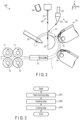
- FIG. 1 is a schematic perspective view showing the main part of a coiling machine 100 according to a first embodiment.
- FIG. 2 is a schematic front view of the coiling machine 100 of FIG. 1 .
- the X-direction, Y-direction, Z-direction, and ⁇ -direction are defined as shown in FIG. 1 and FIG. 2 .
- the X-direction, Y-direction, and Z-direction are orthogonal to each other.
- the X-direction is the wire-feeding direction.
- the Z-direction is the direction in which the helix of the coil spring is formed.
- the ⁇ -direction is the direction in which a wire constituting the coil spring is wound.
- the coiling machine 100 includes a helix forming unit 10, heating unit (laser heating machine 20), cutting unit 30, and control unit 40.
- the helix forming unit 10 forms the wire 1 which is the material for the coil spring into a helical shape while feeding the wire thereto.
- the helix forming unit 10 described above includes a pair of driving rollers 11, a pair of driven rollers 12, wire guide 13, first forming roller 14, second forming roller 15, and pitch tool 16.
- Each of the driving rollers 11 and each of the driven rollers 12 are opposed to each other with a gap held between them.
- each of the driven rollers 12 is rotated through the wire 1.
- the wire 1 pinched between each driving roller 11 and each driven roller 12 is moved in the X-direction shown in FIG. 1 and FIG. 2 .
- the wire 1 is inserted through the wire guide 13.
- the wire guide 13 guides the wire 1 in such a manner that the wire 1 moves straight ahead in the X-direction to thereby lead the wire 1 to the first forming roller 14.
- the first forming roller 14, second forming roller 15, and pitch tool 16 are arranged in this order in the ⁇ -direction and, when viewed from above, the order of their positions is different from the above in the Z-direction.
- the first forming roller 14 guides the wire 1 moving in the X-direction to the second forming roller 15 while bending the wire 1 into an arc-like shape and moving the wire 1 in the Y-direction shown in FIG. 1 .
- the second forming roller 15 guides the wire 1 moving forward in an arc-like shape to the pitch tool 16 while further bending the wire 1 into the arc-like shape.
- the wire 1 guided by the pitch tool 16 moves in the Z-direction shown in FIG. 1 in a helically-formed state.
- the laser heating machine 20 radiates laser light in such a manner as to heat a part of the wire 1 formed into a helical shape. Owing to the irradiation of the laser light, a heated portion 1V the temperature of which is higher than the other portions is formed in the wire 1.
- the laser heating machine 20 described above includes a laser oscillator 21, optical fiber 22, and beam-spot regulator 23.
- the laser oscillator 21 for example, a semiconductor laser configured to generate laser light can be used.
- the optical fiber 22 transmits the laser light generated by the laser oscillator 21 to the beam spot regulator 23.
- the beam spot regulator 23 modifies the beam shape of the laser light into a rectangular shape or circular shape.
- an optical element such as a beam homogenizer or the like can be used.
- the laser heating machine 20 may further include a measuring instrument 24 configured to measure the temperature of the heated portion 1V.
- the measuring instrument 24 includes, for example, a sensor configured to detect the temperature of the heated portion 1V of the wire 1.
- the measuring instrument 24 may be provided on the lateral side of the cutting unit 30.
- the measuring instrument 30 can also be configured in such a manner as to move away from the cutter 31 in conjunction with the operation of the cutter 31.
- the measurement result obtained by the measuring instrument 24 can be used for, for example, control of the timing for cutting the wire 1 to be carried out by the cutting unit 30.
- the measuring instrument 24 is not an indispensable configuration. That is, various conditions concerning cutting of the wire 1 may be set in advance without using the measuring instrument 24, and the cutting unit 30 may cut the heated portion 1V on the basis of the conditions.
- the laser heating machine 20 may further include a migration stage configured to move the beam spot regulator 23 closer to or away from the heated portion 1V of the wire 1.
- the migration stage can be constituted of, for example, a direct-acting stage or robot hand.
- the cutting unit 30 cuts the heated portion 1V of the wire 1 the temperature of which is higher than before being irradiated with the laser light after the irradiation of the laser light is stopped.
- the cutting unit 30 described above includes the cutter 31 and mandrel 32.
- the cutter 31 is arranged at a position between the second forming roller 15 and pitch tool 16, and above these members in the Y-direction.
- the cutter 31 includes a sharp cutting blade the cutting edge of which is in the Z-direction at a tip thereof.
- the cutter 31 is configured to be movable up and down in the Y-direction by means of a direct-acting stage not shown.
- the mandrel 32 is arranged inside the circular arc along which the first forming roller 14, second forming roller 15, and pitch tool 16 are arranged.
- the shape of the mandrel 32 in the X-Y plane is semicircular as shown in, for example, FIG. 2 , and extends to elongate in the Z-direction.
- the mandrel 32 supports the inner circumferential surface of the wire 1 formed into the helical shape on the upper part of the circular arc surface thereof.
- the control unit 40 controls the helix forming unit 10, laser heating machine 20, and cutting unit 30.
- the control unit 40 described above includes a controller 41.
- the controller 41 includes a read only memory (ROM), central processing unit (CPU), and random access memory (RAM).
- ROM stores therein computer programs for controlling the helix forming unit 10, laser heating machine 20, and cutting unit 30.
- the CPU executes the computer programs stored in the ROM.
- the RAM temporarily stores therein, while the computer programs are executed by the CPU, various data items occurring concomitantly with the execution of the computer programs.
- FIG. 3 is a flowchart concerning an operation of the coiling machine 100.
- the operation shown by the flowchart is realized by the controller 41 by executing the computer programs.
- the manufacturing process of the coil spring 2 to be carried out by the coiling machine 100 includes a helix forming step S01, heating step S02, and cutting step S03.
- the wire 1 is formed into a helical shape.
- a part of the wire 1 is irradiated with laser light, whereby the heated portion 1V is formed in the wire 1.
- the heated portion 1V includes a portion made softer than the other portions (base material) of the wire 1.
- the cutting step S03 after the heating step S02 is completed the heated portion 1V of the wire 1 is cut.
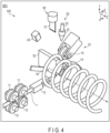
- FIG. 4 is a schematic perspective view of the coiling machine 100 showing a specific example of the helix forming step S01.
- the helix forming unit 10 makes the wire 1 move straight in the X-direction by means of the driving rollers 11 and driven rollers 12 to thereby lead the wire 1 to the wire guide 13.
- the wire 1 output from the wire guide 13 is formed into an arc-like shape by the first forming roller 14 and second forming roller 15.
- the wire 1 formed into the arc-like shape is guided by the pitch tool 16 in such a manner as to be formed into a helical shape having a predetermined pitch. Owing to such an operation, the helical wire 1 is gradually elongated in the Z-direction.
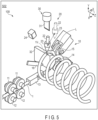
- FIG. 5 is a schematic perspective view of the coiling machine 100 showing a specific example of the heating step S02.
- the laser heating machine 20 directly irradiates, for example, the portion of the wire 1 formed into the helical shape positioned above (below the cutter 31) the end part of the mandrel 32 with laser light.
- the base material of the wire 1 is heated and a softened heated portion 1V is formed.
- the laser heating machine 20 is fixedly arranged at, for example, a predetermined position, and radiates laser light from this position toward a part of the stopped wire 1.
- the laser heating machine 20 may radiate laser light after making the beam spot regulator 23 close to the wire 1 as shown in FIG. 5 .
- the action of the laser heating machine 20 may also be controlled in such a manner that while the heating step S02 is executed, feeding of the wire 1 carried out by the helix forming unit 10 is not stopped, and the laser light irradiation position moves to follow the movement of the cutting position resulting from the coiling operation.
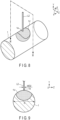
- FIG. 6 is a perspective view showing a first example of the method of softening a part of the wire 1 by heating.
- the laser heating machine 20 irradiates the surface of the wire 1 with laser light L1.
- the laser light L1 has a beam profile elongated in the width direction of the wire 1.
- a heated portion 1V is formed in the irradiated area 1a of the wire 1 irradiated with the laser light L1 and surrounding part thereof.
- FIG. 7 is a cross-sectional view of the wire 1 along line VII-VII in FIG. 6 .
- the heated portion 1V extends not only to the surrounding part of the irradiated area 1a on the surface of the wire 1, but also to the inside of the wire 1.
- the width WD1 of the laser light L1 in the width direction of the wire 1 is less than the diameter R of the wire 1. Accordingly, the most part of the laser light L1 is applied to the wire 1.
- FIG. 8 is a perspective view of the wire 1 showing a second example of the method of softening a part of the wire 1 by heating.
- the laser heating machine 20 irradiates the surface of the wire 1 with laser light L2.
- the laser light L2 has a beam profile of, for example, a circular shape.
- a heated portion 1V is formed as in the case of the first example.
- FIG. 9 is a cross-sectional view of the wire 1 along line IX-IX in FIG. 8 .
- the heated portion 1V extends not only to the surrounding part of the irradiated area 1a on the surface of the wire 1, but also to the inside of the wire 1.
- the width WD2 of the laser light L2 is sufficiently less than the diameter R of the wire 1. Accordingly, the most part of the laser light L2 is applied to the wire 1.
- the laser light L1 or L2 parallel to the Y-direction is applied to the top surface of the wire 1 in the Y-direction
- the irradiation direction of the laser light L1 or L2 is not limited to this.
- the laser light L1 or L2 may also be applied to the wire 1 from the direction intersecting the Y-direction.
- the laser light L1 or L2 may also be applied to the undersurface of the wire 1 in the Y-direction.
- the heated portion 1V may extend to a position deeper inside the wire 1 than the examples shown in FIG. 7 and FIG. 9 .
- the shape of the laser light emitted from the laser heating machine 20 is not limited to the first example and second example.
- the laser light may be applied to only one portion of the wire 1 or may be applied to a plurality of portions thereof.
- the heated portion 1V may include a melt pool formed by melting the base material of the wire 1 by the energy of the laser light.
- the melt pool may spread not only to parts inside the irradiated area 1a but also to the surrounding part thereof.
- FIG. 10 is a schematic perspective view of the coiling machine 100 showing a specific example of the cutting step S03.
- the cutting step S03 is executed after the laser light irradiation is stopped.
- the heated portion 1V of the wire 1 the temperature of which has become higher than before being irradiated with the laser light is cut by the cutting unit 30. Thereby, the coil spring 2 is manufactured.
- the cutter 31 is made to descend toward the vicinity of the part of the wire 1 supported on the mandrel 32. At this time, the wire 1 is cut by the impact applied thereto by the cutter 31.
- the melt pool may solidify within the time when the laser light irradiation is stopped to the time when the cutter 31 operates. Further, the melt pool may solidify after the cutter starts to operate, and when the cutter 31 comes into contact with the surface of the wire 1 to thereby draw heat from the heated portion 1V. As described above, the melt pool solidifies before or during the operation of the cutter 31, whereby it is possible to prevent the molten metal from adhering to the cutter 31.
- the cutter 31 may operate after the laser light irradiation is stopped and, when the temperature of the heated portion 1V lowers to a predetermined target temperature.
- the above-described target temperature may be, for example, the temperature at which the molten base material solidifies.
- the heated portion 1V may be cut without using the measuring instrument 24 by determining in advance a delay time from the stop of laser light irradiation to the start of the operation of the cutter 31.
- the cut-off coil spring 2 has a first end 51 including a first end face 51a, and second end 52 including a second end face 52a. After one coil spring 2 is manufactured, the above-described helix forming step S01, heating step S02, and cutting step S03 are executed again, and then the next coil spring 2 is manufactured. Accordingly, both the first end 51 and second end 52 are formed by cutting after the above-described steps are carried out.
- the shearing force required to cut the wire decreases with the raise in temperature of the wire resulting from heating. Further, even when the temperature of the wire does not reach the melting point, it is possible to reduce the shearing force. Furthermore, such a tendency described above is independent of the diameter of the wire. As one example, it is desirable that when the wire 1 is about to be cut by the cutter 31, the temperature of at least a part of the heated portion 1V be higher than or equal to 500°C.
- a part of the wire 1 formed into a helical shape is heated by laser light, and the portion (heated portion 1V) the temperature of which is higher than before being irradiated with the laser light after the irradiation of the laser light is stopped is cut by the cutting components (cutter 31 and mandrel 32).
- the cutting components cutter 31 and mandrel 32.
- the laser heating machine 20 When the laser heating machine 20 is used as in the case of this embodiment, it is possible to selectively and rapidly heat the portion to be cut by means of laser light.
- the laser heating machine 20 When the laser heating machine 20 is used, it is possible to arbitrarily set the heat input amount of heat to be input to the portion to be irradiated with laser light by adjusting the drive current of the laser oscillator 21. Further, it is possible to increase/decrease the output of the laser light by making a quick response to the adjustment of the drive current. Furthermore, it is possible to make the heated portion 1V carry out rapid self-cooling by stopping the laser light irradiation carried out by the laser heating machine 20.
- the term 'rapid self-cooling' implies that the heated portion 1V is rapidly cooled without aggressively cooling the heated portion 1V by using members and devices for cooling.
- the laser heating machine 20 it is possible for the laser heating machine 20 to arbitrarily set the irradiated area 1a to be irradiated with the laser light and heated portion 1V of the wire 1 by adjusting the irradiation angle of the laser light relative to the wire 1 or by using a lens or mirror. Accordingly, it is possible for the laser heating machine 20 to heat an arbitrary area of the wire 1 to an arbitrary temperature with a high degree of responsiveness in accordance with the thickness of the wire 1, material for the wire 1, required takt time (cycle time), and the like.
- the heated portion 1V in the state where the portion 1V is softened by the high temperature is cut, whereby the reaction force received by the cutter 31 and mandrel 32 from the wire 1 at the time of cutting is reduced. Accordingly, it is possible to suppress wear and tear of the cutter 31 and mandrel 32, and damage to these members. As a result, it is possible to make the replacement cycle of the cutter 31 or mandrel 32 longer than ever before and thereby reduce the running cost, and to lower the specification of abrasion resistance property or the like required of the materials for the cutter 31 and mandrel 32 and thereby form these members at lower costs than ever before. Further, it is possible to suppress lowering of the operating rate of the coiling machine 100 concomitant with the replacement of the cutter 31 and mandrel 32.
- the wire 1 is not cut by using only the laser light irradiation, the wire 1 is cut by further using the cutter 31.
- the laser heating machine 20 radiates laser light not for the purpose of cutting the wire 1 but for the purpose of softening the wire 1, whereby it is possible to make the intensity of the laser light lower as compared with the case where the wire 1 is cut by only the laser light.
- the laser heating machine 20 radiates laser light not for the purpose of cutting the wire 1 but for the purpose of softening the wire 1, and hence the laser heating machine 20 need not necessarily irradiate the entire area of the position scheduled to be cut and, it is sufficient if the laser heating machine 20 can irradiate a part of the wire 1 in the width direction with laser light as shown in, for example, FIGS. 6 to 9 . More specifically, it is possible for the laser heating machine 20 to irradiate the central part of the wire 1 with laser light while avoiding both the end parts of the wire 1 in the width direction thereof.
- the laser heating machine 20 radiates laser light not for the purpose of cutting the wire 1 but for the purpose of softening the wire 1, and hence the laser heating machine 20 need not radiate laser light in such a manner as to penetrate and split up the wire 1. Accordingly, it is possible to largely simplify or decommission the configuration for shielding the laser light as compared with the conventional coiling machine configured to cut the wire by means of laser light.
- the wire 1 is cut by only laser light, it is necessary to relatively enhance the intensity of the laser light, and hence it is difficult to form the first end face 51a and second end face 52a flat. Further, when the wire 1 is cut by only the cutter without using laser light, it is necessary to apply strong shearing force to the wire 1, and hence large unevenness is liable to occur on each of the end faces 51a and 52a. Conversely, in this embodiment, the wire 1 is cut not only by means of laser light irradiation, but also by means of the cutter 31, and thus it is possible to make the intensity of the laser light lower, and make the shearing force of the cutter 31 less, whereby it becomes possible to form the end faces 51a and 52a flat. As a result, it is possible to obtain a coil spring 2 excellent in quality.
- the heated portion 1V when the heated portion 1V is at least partially heated to a temperature higher than or equal to 500°C at the time of cutting by the cutter 31, it is possible to cut the wire 1 in the high-temperature solid state where the heated portion 1V is sufficiently softened (working resistance of the wire 1 is sufficiently reduced).
- carbon steel to be generally used as a material for the wire 1, by heating the steel to a temperature higher than or equal to about 500°C, the tensile strength (TS) thereof becomes about half the TS at normal temperature or less, and it is possible to easily cut the steel by the cutter 31.
- the heated portion 1V when a melt pool is formed at the heated portion 1V, it is possible to make the heated portion 1V extend to a position deep inside the wire 1. Thereby, the wire 1 is softened up to the part thereof deep inside, and cutting of the wire 1 by the cutter 31 is further facilitated.
- a second embodiment will be described below.
- appropriate conditions for cutting the wire 1 by using the above-described coiling machine 100 will mainly be disclosed.
- the configuration of the coiling machine and flow of the manufacturing method of the coil spring using the coiling machine 100 are identical to the first embodiment.
- FIG. 11 is a schematic cross-sectional view of the wire 1 irradiated with laser light.
- the surface of the wire 1 is irradiated with laser light (L2) having a shape shown in FIG. 8 , and melt pool is formed is assumed.
- O in FIG. 11 indicates the center of the irradiated area irradiated with the laser light on the outer circumferential surface of the wire 1.
- this irradiation center O corresponds to a position irradiated with the peak part of the beam profile of the laser light having the highest intensity. Further, it is also possible to consider the irradiation center O as the center of the melt pool.
- the heated portion 1V is formed.
- a melt pool is formed around the irradiation center O .
- the melt pool is solidified by subsequent cooling and a quench-hardened zone 1C is formed.
- a heat-affected zone (HAZ) 1H which is not melted but is changed to be different in characteristics from the base material of the wire 1 by the heat at the time of laser light irradiation is formed.
- the heated portion 1V includes the quench-hardened zone 1C and heat affected zone 1H.
- FIG. 11 a result of measuring the Vickers hardness as to each of the quench-hardened zone 1C, heat affected zone 1H, and base material of the wire 1 is shown.
- the quench-hardened zone 1C as a whole has higher hardness as compared with the base material.
- the heat affected zone 1H as a whole has lower hardness as compared with the base metal. The hardness of the heat affected zone 1H gradually becomes higher from the vicinity of the quench-hardened zone 1C toward the base material.
- the distribution of hardness is not uniform. Accordingly, it is necessary to appropriately determine the positional relationships between the positions of the cutter 31 and mandrel 32, and irradiated area irradiated with laser light.
- FIG. 12 is cross-sectional view showing an example of appropriate positional relationships between the cutter 31, mandrel 32, and irradiated area irradiated with laser light.
- the wire 1 formed into the helical shape is fed to a position between the cutter 31 and mandrel 32.
- a clearance G is provided in the feed direction ( ⁇ -direction) of the wire 1, between the end part 31a of the cutter and end part 32a of the mandrel 32.
- the center of the clearance G in the ⁇ -direction is referred to as the clearance center C.
- the clearance center C and irradiation center O are shifted from each other in the ⁇ -direction. More specifically, the irradiation center O is positioned on the cutter 31 side (downstream side in the ⁇ -direction) of the clearance center C.
- the heated portion 1V includes the melt pool 1P which becomes the quench-hardened zone 1C after solidification.
- the melt pool 1P and clearance center C are overlapped with each other. Further, the melt pool 1P is overlapped with the end part 31a of the cutter 31 when viewed from the Y-direction.
- the melt pool 1P is not overlapped with the end part 32a of the mandrel 32 when viewed from the Y-direction.
- the end part 32a of the mandrel 32 and a part of the heat affected zone 1H positioned on the upstream side of the melt pool 1P overlap each other when viewed from the Y-direction.
- FIG. 13 is a cross-sectional view showing a state where the wire 1 is cut by lowering the cutter 31 in the Y-direction from the state shown in FIG. 12 .
- the melt pool 1P is already solidified or the melt pool 1P is solidified by being deprived of heat thereof by the contact with the cutter 31. Accordingly, while the wire 1 is cut, the quench-hardened zone 1C is already formed. It should be noted that when the wire 1 to be cut, part of the melt pool 1P may remain inside the heated portion 1V.
- the tip part of the cutter 31 applies an impact to the outer circumferential surface of a part of the wire 1 protruding from the end part 32a of the mandrel 32, shearing force is applied to the heated portion 1V and surrounding par thereof, whereby the wire 1 is broken at around the portion 1V.
- the cutter lowers to, for example, a position close to the axis of the wire 1 at the maximum.
- a dent B attributable to the cutter 31 is formed on the cut wire 1, i.e., on the coil spring 2, a dent B attributable to the cutter 31 is formed.
- the quench-hardened zone 1C and heat affected zone are overlapped with the dent B, they may be shifted from each other.
- the heat affected zone 1H is lower in hardness than the quench-hardened zone 1C and base material of the wire 1. Accordingly, when the cutter 31 applies an impact to the wire 1, in the heated portion 1V, the heat affected zone 1H is susceptible to fracture. In particular, when the irradiation center O is shifted from the clearance center C to the cutter 31 side as shown in FIG. 12 , it is possible to effectively apply the burden to a part of the heat affected zone 1H positioned on the upstream side of the melt pool 1P in the ⁇ -direction and thereby fracture the wire 1 at this part.
- FIG. 14 is a schematic side view of the coil spring 2 cut off from the wire 1 by the method shown in FIG. 12 and FIG. 13 .
- the coil spring 2 has the first end 51 including the first end face 51a, and second end 52 including the second end face 52a.
- the first end face 51a corresponds to a fracture surface of the coil spring 2 cut off from the wire 1 in FIG. 13 .
- the first end 51 includes a first irradiation scar M1 of the laser light and dent B of the cutter 31.
- the first irradiation scar M1 includes the quench-hardened zone 1C and heat affected zone 1H (first heat affected zone).
- the second end face 52a corresponds to the fracture surface of the wire 1 left on the mandrel 32 when the coil spring 2 manufactured before the current coil spring 2 is cut off from the wire 1.
- the second end 52 includes a second irradiation scar M2 of the laser light.
- the second irradiation scar M2 includes the heat affected zone 1H (second heat affected zone).
- the second irradiation scar M2 includes no quench-hardened zone 1C.
- the second irradiation scar M2 may include, for example, a quench-hardened zone 1C less than the first irradiation scar M1.
- the heat affected zone 1H included in the first irradiation scar M1 extends to at least a part of the first end face 51a. Further, the heat affected zone 1H included in the second irradiation scar M2 extends to at least a part of the second end face 52a.
- the quench-hardened zone 1C included in the first irradiation scar M1 does not extend to the first end face 51a. However, a part of the quench-hardened zone 1C may extend to the first end face 51a. In this case, it is desirable that the area of the quench-hardened zone 1C be less than the area of the heat affected zone 1H in the first end face 51a.
- FIG. 15 shows a first example of the first irradiation scar M1, second irradiation scar M2, and dent B, and shows a schematic cross-sectional view of the coil spring 2 at each of the first end 51 and second end 52.
- the cross section shown on the left side in FIG. 15 corresponds to the cross section of the first end 51 along line CA-CA in FIG. 14 .
- the cross section shown on the right side in FIG. 15 corresponds to the cross section of the second end 52 along line CB-CB in FIG. 14 .
- the upper surface in FIG. 15 is the outer circumferential surface 2a of the coil spring 2
- lower surface in FIG. 15 is the inner circumferential surface 2b of the coil spring 2.
- the broken line arrow in FIG. 15 indicates the irradiation direction D1 of the laser light at the time of heating.
- the solid line arrow indicates the moving direction D2 of the cutter 31 at the time of cutting.
- each of the irradiation direction D1 and moving direction D2 is the direction from the upper part in FIG. 15 to each end 51, 52. However, when the ends 51 and 52 are viewed from a direction different from the direction of the cross sections shown in FIG. 15 , these directions D1 and D2 may intersect each other.
- the first irradiation scar M1 includes the quench-hardened zone 1C and heat affected zone 1H. Further, the whole surface of the first irradiation scar M1 is overlapped with the dent B.
- the second irradiation scar M2 includes the heat affected zone 1H, and includes no quench-hardened zone 1C. Further, on the second end 52, no dent B is formed.
- Each of the first irradiation scar M1, second irradiation scar M2, and dent B is formed on the outer circumferential surface.
- FIG. 16 shows a second example of the first irradiation scar M1, second irradiation scar M2, and dent B, and shows a schematic cross-sectional view of the coil spring 2 at each of the first end 51 and second end 52 as in the case of FIG. 15 .
- the irradiation direction D1 forms an acute angle (for example 40°) with the moving direction D2.
- the first irradiation scar M1 includes a part thereof overlapping the dent B and part thereof not overlapping the dent B.
- the cutter 31 comes into contact with a hard part (base material) other than the heated portion 1V at the time of cutting, and hence it is possible to make the dent B less as compared with the first example.
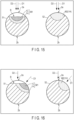
- FIG. 17 shows a third example of the first irradiation scar M1, second irradiation scar M2, and dent B, and shows a schematic cross-sectional view of the coil spring 2 at each of the first end 51 and second end 52 as in the case of FIG. 15 .
- the irradiation direction D1 and moving direction D2 are directions opposite to each other.
- the first irradiation scar M1 and second irradiation scar M2 are formed on the inner circumferential surface 2b.
- the dent B is formed on the outer circumferential surface 2a.
- the cutter 31 does not come into contact with the heated portion 1V at the time of cutting, and hence the dent can be made further less as compared with the second example.
- the first irradiation scar M1, second irradiation scar M2, and dent B can be formed in various aspects.
- the dent B may be formed not only at the first end 51 but also at the second end 52.
- the dent B of the second end 52 may be less than the dent B of the first end 51.
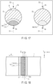
- FIG. 18 is a schematic plan view of the wire 1 after being irradiated with the laser light having the shape shown in FIG. 6 .
- the irradiation center O of the laser light extends in the direction orthogonal to the axial direction of the wire 1. Accordingly, in the heated portion 1V formed by the irradiation of this laser light, the melt pool 1P (or quench-hardened zone 1C after solidification) has a shape elongated in the width direction of the wire 1.
- the heat affected zone 1H around the quench-hardened zone 1C has a shape elongated in the width direction of the wire 1.
- the heat affected zone 1H extends from one end to the other end of the wire 1 in the width direction thereof, the example is not limited to this.
- a distance D is provided between the irradiation center O and clearance center C by shifting the irradiation center O from the clearance center C to the cutter 31 side (left side in FIG. 18 ).
- the clearance center C is overlapped with the melt pool 1P.
- the end part 32a of the mandrel 32 is overlapped with a part of the heat affected zone 1H positioned on the upstream side of the melt pool 1P in the ⁇ -direction.
- the inventors of the present invention have carried out, a plurality of times, the experiment of cutting the wire 1 for each of the case where the irradiation center O and clearance center C are made overlapped with each other, case where the irradiation center O is shifted from the clearance center C to the cutter 31 side, and case where the irradiation center O is shifted from the clearance center C to the mandrel 32 side.
- the fracture surface of the case where the irradiation center O is shifted from the clearance center C to the cutter 31 side is the flattest
- fracture surface of the case where the irradiation center O and clearance center C are made overlapped with each other is the second flattest. From this result, it can be seen that by shifting the irradiation center O from the clearance center C to the cutter 31 side as in the case of this embodiment, the coil spring 2 having the flatter first end face 51a and flatter second end face 52a can be obtained.
- the heat affected zone 1H in the coil spring 2 manufactured by cutting the wire 1 under the condition of this embodiment, the heat affected zone 1H widely spreads in each of the first end face 51a and second end face 52a. In this case, the hardness of the heat affected zone 1H is lower as compared with the other parts, and hence the residual stress is reduced in this zone. Further, the above-described process of removing the residual stress can be omitted.
- the heat affected zone 1H spreads from one end of the wire 1 in the width direction thereof to the other end thereof.
- the heat affected zone 1H spreads over a wider range of the fracture surface. Accordingly, it is possible to more obviously obtain the effect of suppressing breakage of the end faces 51a and 52a.
- the configuration in which the coiling machine 100 cuts the heated portion 1V by means of the cutter 31 is exemplified.
- the coiling machine 100 is not limited to the configuration described above, and may cut the heated portion 1V of the wire 1 by a cutting operation using a rotary saw.
- the aspects of the coil springs 2 to be manufactured by the coiling machine 100 widely vary and, for example, the coil diameter and pitch may change in the axial direction of the coil spring. That is, the coil springs 2 to be manufactured by the coiling machine 100 may include coil springs of various aspects such as a cylindrical coil spring, barrel-type coil spring, hourglass-type coil spring, tapered coil spring, irregular-pitch coil spring, and coil spring including a negative-pitch part, and the like.
Landscapes
- Engineering & Computer Science (AREA)
- Mechanical Engineering (AREA)
- Physics & Mathematics (AREA)
- Optics & Photonics (AREA)
- Plasma & Fusion (AREA)
- Wire Processing (AREA)
- Particle Accelerators (AREA)
- Springs (AREA)
Claims (5)
- Wickelmaschine (100), die Folgendes umfasst:eine Spiralformungseinheit (10), die dazu eingerichtet ist, einen Draht (1) in eine Spiralform zu formen, während der Draht ihr zugeführt wird;eine Laserheizmaschine (20), die dazu eingerichtet ist, den Draht (1) mit Laserlicht zu bestrahlen, um dadurch einen Abschnitt (1V) des Drahts (1) zu erhitzen; undSchneidkomponenten (31, 32), die einen Wickeldorn (32), der dazu eingerichtet ist, eine innere Umfangsfläche des in eine Spiralform geformten Drahts (1) darauf zu tragen, und eine Schneidvorrichtung (31) enthalten, die dazu eingerichtet ist, einen Schlag auf eine äußere Umfangsfläche eines Teils des Drahts (1) aufzubringen, der aus einem Endteil (32a) des Wickeldorns (32) hervorsteht, um dadurch den Draht (1) zu schneiden, und eine Steuereinheit (40), die eine Steuerung (41) umfasst, die dazu eingerichtet ist, die Spiralformungseinheit (10), die Laserheizmaschine (20) und die Schneidkomponenten (31, 32) zu steuern,wobei in einer Zuführrichtung des Drahts (1) zwischen der Schneidvorrichtung (31) und dem Endteil (32a) des Wickeldorns (32) ein Zwischenraum (G) vorgesehen ist,dadurch gekennzeichnet, dass die Steuerung (41) dazu eingerichtet ist, die Spiralformungseinheit (10), die Laserheizmaschine (20) und die Schneidkomponenten (31, 32) zu steuern, um den Abschnitt (1V) des Drahts (1), der auf eine Temperatur von mehr als oder gleich 500 °C erhitzt ist, nachdem die Bestrahlung mit dem Laserlicht gestoppt wurde, zu schneiden, so dass, wenn die Schneidvorrichtung (31) einen Schlag auf den Draht (1) aufbringt, eine Mitte (C) des Zwischenraums (G) und eine Mitte (O) eines bestrahlten Bereichs (1a), der mit dem Laserlicht auf dem Draht (1) bestrahlt wird, in der Zuführrichtung voneinander verschoben werden und so dass die Mitte (O) des bestrahlten Bereichs (1a) auf der Seite der Schneidvorrichtung (31) der Mitte (C) des Zwischenraums (G) in der Zuführrichtung positioniert wird.
- Wickelmaschine (100) nach Anspruch 1, wobeidie Laserheizmaschine (20) dazu eingerichtet ist, den Draht (1) mit dem Laserlicht zu bestrahlen, um dadurch ein Schmelzbad und eine Wärmeeinflusszone (1H) um das Schmelzbad herum im Draht (1) zu bilden, unddie Schneidkomponenten (31, 32) dazu eingerichtet sind, die Wärmeeinflusszone (1H) des Drahts (1) zu schneiden.
- Wickelmaschine (100) nach Anspruch 1, wobeidie Laserheizmaschine (20) den Draht (1) mit dem Laserlicht bestrahlt, um dadurch ein Schmelzbad und eine Wärmeeinflusszone (1H) um das Schmelzbad herum im Draht (1) zu bilden, undwenn die Schneidvorrichtung (31) einen Schlag auf den Draht (1) aufbringt, sich bei Betrachtung aus einer Bewegungsrichtung der Schneidvorrichtung (31) der Endteil des Wickeldorns (32) und ein Teil der Wärmeeinflusszone (1H), die auf der stromaufwärtigen Seite des Schmelzbads in der Zuführrichtung positioniert ist, miteinander überschneiden.
- Herstellungsverfahren für eine Spiralfeder (2), das mit einer Wickelmaschine (100) nach einem der Ansprüche 1 bis 3 durchgeführt wird und die folgenden Schritte umfasst:Bestrahlen des in die Spiralform geformten Drahts (1) mit dem Laserlicht mit der Laserheizmaschine (20), um dadurch einen Abschnitt (1V) des Drahts (1) zu erhitzen;Zuführen des in eine Spiralform geformten Drahts (1) zu einer Position zwischen einem Wickeldorn (32), der dazu eingerichtet ist, eine innere Umfangsfläche des in die Spiralform geformten Drahts (1) darauf zu tragen, und der Schneidvorrichtung (31),Schneiden des Abschnitts (1V) des Drahts (1), der auf eine Temperatur von mehr als oder gleich 500 °C erhitzt ist, nachdem die Bestrahlung mit dem Laserlicht gestoppt wurde, mit den Schneidkomponenten (31, 32),wobei der Schritt des Schneidens des Abschnitts (1V) des Drahts (1), wenn der Draht geschnitten werden soll, das Aufbringen eines Schlags auf eine äußere Umfangsfläche eines Teils des Drahts (1) umfasst, der aus einem Endteil (32a) des Wickeldorns (32) hervorsteht,wobei in einer Zuführrichtung des Drahts (1) zwischen der Schneidvorrichtung (31) und dem Endteil (32a) des Wickeldorns (32) ein Zwischenraum (G) vorgesehen ist, undwenn die Schneidvorrichtung (31) einen Schlag auf den Draht (1) aufbringt, eine Mitte (C) des Zwischenraums (G) und eine Mitte (O) eines bestrahlten Bereichs (1a), der mit dem Laserlicht auf dem Draht (1) bestrahlt wird, in der Zuführrichtung voneinander verschoben werden, undwobei die Mitte (O) des bestrahlten Bereichs (1a) auf der Seite der Schneidvorrichtung (31) der Mitte (C) des Zwischenraums (G) in der Zuführrichtung positioniert wird.
- Herstellungsverfahren für eine Spiralfeder (2) nach Anspruch 4, wobei der Draht (1) mit dem Laserlicht bestrahlt wird, wodurch ein Schmelzbad und eine Wärmeeinflusszone (1H) um das Schmelzbad herum im Draht (1) gebildet werden, und
wenn die Schneidvorrichtung (31) einen Schlag auf den Draht (1) aufbringt, sich bei Betrachtung aus einer Bewegungsrichtung der Schneidvorrichtung (31) der Endteil (32a) des Wickeldorns (32) und ein Teil der Wärmeeinflusszone (1H), die auf der stromaufwärtigen Seite des Schmelzbads in der Zuführrichtung positioniert ist, miteinander überschneiden.
Applications Claiming Priority (2)
| Application Number | Priority Date | Filing Date | Title |
|---|---|---|---|
| JP2019019754 | 2019-02-06 | ||
| PCT/JP2019/046219 WO2020161998A1 (ja) | 2019-02-06 | 2019-11-26 | コイリングマシン、コイルばねの製造方法およびコイルばね |
Publications (3)
| Publication Number | Publication Date |
|---|---|
| EP3922377A1 EP3922377A1 (de) | 2021-12-15 |
| EP3922377A4 EP3922377A4 (de) | 2022-10-26 |
| EP3922377B1 true EP3922377B1 (de) | 2025-01-22 |
Family
ID=71947068
Family Applications (1)
| Application Number | Title | Priority Date | Filing Date |
|---|---|---|---|
| EP19914558.2A Active EP3922377B1 (de) | 2019-02-06 | 2019-11-26 | Wickelmaschine, verfahren zur herstellung einer schraubenfeder und schraubenfeder |
Country Status (7)
| Country | Link |
|---|---|
| US (1) | US20210362274A1 (de) |
| EP (1) | EP3922377B1 (de) |
| JP (3) | JP7066880B2 (de) |
| CN (1) | CN113365755B (de) |
| HU (1) | HUE070750T2 (de) |
| MX (1) | MX2021008990A (de) |
| WO (1) | WO2020161998A1 (de) |
Families Citing this family (6)
| Publication number | Priority date | Publication date | Assignee | Title |
|---|---|---|---|---|
| JP7203910B1 (ja) * | 2021-07-01 | 2023-01-13 | 日本発條株式会社 | コイルばね、懸架装置およびコイルばねの製造方法 |
| CN113857394B (zh) * | 2021-09-22 | 2024-10-15 | 安徽环新集团股份有限公司 | 活塞环坯料绕环机 |
| CN114898947B (zh) * | 2022-05-10 | 2024-02-09 | 江苏欣达通信科技股份有限公司 | 一种弹簧式跳线加工设备及加工方法 |
| JP7840815B2 (ja) | 2022-08-15 | 2026-04-06 | 日本発條株式会社 | コイリングマシンおよびコイルばねの製造方法 |
| JP7840814B2 (ja) | 2022-08-15 | 2026-04-06 | 日本発條株式会社 | コイリングマシンおよびコイルばねの製造方法 |
| JP7749872B1 (ja) * | 2025-04-10 | 2025-10-06 | 日本発條株式会社 | コイリングマシンおよびコイルばねの製造方法 |
Family Cites Families (19)
| Publication number | Priority date | Publication date | Assignee | Title |
|---|---|---|---|---|
| US2995648A (en) * | 1958-08-11 | 1961-08-08 | Staples & Company Ltd | Spring coiling apparatus |
| GB1374915A (en) * | 1971-03-08 | 1974-11-20 | Hattan M Green W P | Formation of nuts |
| JPS6250028A (ja) | 1985-08-27 | 1987-03-04 | High Frequency Heattreat Co Ltd | 高強度太径線材使用冷間成形コイルばね成形時の切断方法 |
| JPH0729164B2 (ja) * | 1993-01-27 | 1995-04-05 | 株式会社板屋製作所 | バネ製造装置 |
| JP3324078B2 (ja) * | 1996-12-19 | 2002-09-17 | 旭精機工業株式会社 | コイルばねの切断方法 |
| JP2000107827A (ja) * | 1998-10-07 | 2000-04-18 | Toshikazu Okuno | 線材加工機における加熱切断方法及び装置 |
| JP3854242B2 (ja) * | 2003-04-30 | 2006-12-06 | 株式会社板屋製作所 | スプリング製造装置及び当該装置を用いたワイヤの切断方法 |
| JP4685981B2 (ja) * | 2004-07-22 | 2011-05-18 | 新興機械工業株式会社 | ばね製造機の線材切断装置 |
| JP2005138284A (ja) | 2005-02-07 | 2005-06-02 | Matsushita Electric Works Ltd | プリプレグの切断方法 |
| US8136379B2 (en) * | 2007-06-05 | 2012-03-20 | Kabushiki Kaisha Itaya Seisaku Sho | Helical part manufacturing apparatus and control method thereof |
| JP2009012037A (ja) * | 2007-07-04 | 2009-01-22 | Nippon Bane Kogaku Kenkyusho:Kk | コイルバネ用レーザマーキング装置、コイルバネ製造装置およびレーザマーキングを施されたコイルバネ |
| JP5064590B1 (ja) | 2011-08-11 | 2012-10-31 | 日本発條株式会社 | 圧縮コイルばねおよびその製造方法 |
| DE102012204513B3 (de) * | 2012-03-21 | 2013-09-19 | Wafios Ag | Verfahren und Vorrichtung zur Herstellung von Schraubenfedern durch Federwinden |
| JP5361098B1 (ja) * | 2012-09-14 | 2013-12-04 | 日本発條株式会社 | 圧縮コイルばねおよびその製造方法 |
| DE102013207028B3 (de) * | 2013-04-18 | 2014-06-26 | Wafios Ag | Federwindemaschine mit einstellbarer Schnitteinrichtung |
| DE102013214161B4 (de) * | 2013-07-18 | 2015-05-07 | Wafios Ag | Verfahren und Vorrichtung zur Herstellung von Schraubenfedern durch Federwinden |
| CN103753223A (zh) * | 2013-12-11 | 2014-04-30 | 广州中国科学院先进技术研究所 | 一种激光辅助钻孔方法及装置 |
| JP6359904B2 (ja) | 2014-07-18 | 2018-07-18 | 日立Geニュークリア・エナジー株式会社 | 切断装置及び切断方法並びに切断装置を用いた解体システム |
| CN106040920B (zh) * | 2016-08-22 | 2018-03-09 | 陶胜治 | 弹簧钢丝自动卷簧机应力折断工艺 |
-
2019
- 2019-11-26 WO PCT/JP2019/046219 patent/WO2020161998A1/ja not_active Ceased
- 2019-11-26 JP JP2020570383A patent/JP7066880B2/ja active Active
- 2019-11-26 CN CN201980090847.4A patent/CN113365755B/zh active Active
- 2019-11-26 MX MX2021008990A patent/MX2021008990A/es unknown
- 2019-11-26 HU HUE19914558A patent/HUE070750T2/hu unknown
- 2019-11-26 EP EP19914558.2A patent/EP3922377B1/de active Active
-
2021
- 2021-08-06 US US17/395,684 patent/US20210362274A1/en active Pending
-
2022
- 2022-04-27 JP JP2022073234A patent/JP7497386B2/ja active Active
- 2022-04-27 JP JP2022073233A patent/JP7225457B2/ja active Active
Also Published As
| Publication number | Publication date |
|---|---|
| JP2022097584A (ja) | 2022-06-30 |
| EP3922377A1 (de) | 2021-12-15 |
| JP7066880B2 (ja) | 2022-05-13 |
| JPWO2020161998A1 (ja) | 2021-11-11 |
| EP3922377A4 (de) | 2022-10-26 |
| CN113365755A (zh) | 2021-09-07 |
| CN113365755B (zh) | 2023-05-05 |
| JP7225457B2 (ja) | 2023-02-20 |
| JP7497386B2 (ja) | 2024-06-10 |
| WO2020161998A1 (ja) | 2020-08-13 |
| JP2022109282A (ja) | 2022-07-27 |
| MX2021008990A (es) | 2021-09-08 |
| HUE070750T2 (hu) | 2025-07-28 |
| US20210362274A1 (en) | 2021-11-25 |
Similar Documents
| Publication | Publication Date | Title |
|---|---|---|
| EP3922377B1 (de) | Wickelmaschine, verfahren zur herstellung einer schraubenfeder und schraubenfeder | |
| TWI483801B (zh) | 鋼板之雷射熔接方法及雷射熔接裝置 | |
| EP3332904B1 (de) | Laserschweissverfahren | |
| US20250178069A1 (en) | Coiling machine and production method for coil springs | |
| US20250178068A1 (en) | Coiling machine and coil spring manufacturing method | |
| EP3525972B1 (de) | Verfahren zur herstellung einer verzahnten klinge und vorrichtung zur herstellung solch einer klinge | |
| JP2006347168A (ja) | レーザによって脆性材料の平坦な加工物を複数回割断するための装置 | |
| US10638544B2 (en) | Heating method, heating apparatus and method of manufacturing press-molded article | |
| US10092976B2 (en) | Machining metal removal control | |
| JP6535478B2 (ja) | レーザ光によるワークの前処理方法及びレーザ加工機 | |
| US11772144B2 (en) | Process for the production of thin-walled hollow profiles which are composed of nonferrous metals and have small diameters | |
| JPH05185174A (ja) | 細線切断方法 | |
| JP7749872B1 (ja) | コイリングマシンおよびコイルばねの製造方法 | |
| JP2021089284A (ja) | 穿孔された金属製中空形状物内に取り付けられた光ファイバ導波路センサの連続製造の方法 | |
| WO1999036200A1 (en) | A welding method, a heat exchanger tube, and an apparatus for the manufacturing of a heat exchanger tube | |
| CN120985074A (zh) | 一种激光软化装置、钢带加工系统与方法 |
Legal Events
| Date | Code | Title | Description |
|---|---|---|---|
| STAA | Information on the status of an ep patent application or granted ep patent |
Free format text: STATUS: THE INTERNATIONAL PUBLICATION HAS BEEN MADE |
|
| PUAI | Public reference made under article 153(3) epc to a published international application that has entered the european phase |
Free format text: ORIGINAL CODE: 0009012 |
|
| STAA | Information on the status of an ep patent application or granted ep patent |
Free format text: STATUS: REQUEST FOR EXAMINATION WAS MADE |
|
| 17P | Request for examination filed |
Effective date: 20210805 |
|
| AK | Designated contracting states |
Kind code of ref document: A1 Designated state(s): AL AT BE BG CH CY CZ DE DK EE ES FI FR GB GR HR HU IE IS IT LI LT LU LV MC MK MT NL NO PL PT RO RS SE SI SK SM TR |
|
| DAV | Request for validation of the european patent (deleted) | ||
| DAX | Request for extension of the european patent (deleted) | ||
| A4 | Supplementary search report drawn up and despatched |
Effective date: 20220927 |
|
| RIC1 | Information provided on ipc code assigned before grant |
Ipc: B21F 35/00 20060101ALI20220921BHEP Ipc: B21F 11/00 20060101AFI20220921BHEP |
|
| STAA | Information on the status of an ep patent application or granted ep patent |
Free format text: STATUS: EXAMINATION IS IN PROGRESS |
|
| 17Q | First examination report despatched |
Effective date: 20230601 |
|
| GRAP | Despatch of communication of intention to grant a patent |
Free format text: ORIGINAL CODE: EPIDOSNIGR1 |
|
| STAA | Information on the status of an ep patent application or granted ep patent |
Free format text: STATUS: GRANT OF PATENT IS INTENDED |
|
| INTG | Intention to grant announced |
Effective date: 20240925 |
|
| GRAS | Grant fee paid |
Free format text: ORIGINAL CODE: EPIDOSNIGR3 |
|
| GRAA | (expected) grant |
Free format text: ORIGINAL CODE: 0009210 |
|
| STAA | Information on the status of an ep patent application or granted ep patent |
Free format text: STATUS: THE PATENT HAS BEEN GRANTED |
|
| P01 | Opt-out of the competence of the unified patent court (upc) registered |
Free format text: CASE NUMBER: APP_61027/2024 Effective date: 20241113 |
|
| AK | Designated contracting states |
Kind code of ref document: B1 Designated state(s): AL AT BE BG CH CY CZ DE DK EE ES FI FR GB GR HR HU IE IS IT LI LT LU LV MC MK MT NL NO PL PT RO RS SE SI SK SM TR |
|
| REG | Reference to a national code |
Ref country code: GB Ref legal event code: FG4D |
|
| REG | Reference to a national code |
Ref country code: CH Ref legal event code: EP |
|
| REG | Reference to a national code |
Ref country code: IE Ref legal event code: FG4D |
|
| REG | Reference to a national code |
Ref country code: DE Ref legal event code: R096 Ref document number: 602019065269 Country of ref document: DE |
|
| REG | Reference to a national code |
Ref country code: NL Ref legal event code: MP Effective date: 20250122 |
|
| PG25 | Lapsed in a contracting state [announced via postgrant information from national office to epo] |
Ref country code: NL Free format text: LAPSE BECAUSE OF FAILURE TO SUBMIT A TRANSLATION OF THE DESCRIPTION OR TO PAY THE FEE WITHIN THE PRESCRIBED TIME-LIMIT Effective date: 20250122 |
|
| PG25 | Lapsed in a contracting state [announced via postgrant information from national office to epo] |
Ref country code: RS Free format text: LAPSE BECAUSE OF FAILURE TO SUBMIT A TRANSLATION OF THE DESCRIPTION OR TO PAY THE FEE WITHIN THE PRESCRIBED TIME-LIMIT Effective date: 20250422 |
|
| PG25 | Lapsed in a contracting state [announced via postgrant information from national office to epo] |
Ref country code: FI Free format text: LAPSE BECAUSE OF FAILURE TO SUBMIT A TRANSLATION OF THE DESCRIPTION OR TO PAY THE FEE WITHIN THE PRESCRIBED TIME-LIMIT Effective date: 20250122 |
|
| PG25 | Lapsed in a contracting state [announced via postgrant information from national office to epo] |
Ref country code: PL Free format text: LAPSE BECAUSE OF FAILURE TO SUBMIT A TRANSLATION OF THE DESCRIPTION OR TO PAY THE FEE WITHIN THE PRESCRIBED TIME-LIMIT Effective date: 20250122 |
|
| PG25 | Lapsed in a contracting state [announced via postgrant information from national office to epo] |
Ref country code: ES Free format text: LAPSE BECAUSE OF FAILURE TO SUBMIT A TRANSLATION OF THE DESCRIPTION OR TO PAY THE FEE WITHIN THE PRESCRIBED TIME-LIMIT Effective date: 20250122 |
|
| REG | Reference to a national code |
Ref country code: LT Ref legal event code: MG9D |
|
| PG25 | Lapsed in a contracting state [announced via postgrant information from national office to epo] |
Ref country code: IS Free format text: LAPSE BECAUSE OF FAILURE TO SUBMIT A TRANSLATION OF THE DESCRIPTION OR TO PAY THE FEE WITHIN THE PRESCRIBED TIME-LIMIT Effective date: 20250522 Ref country code: NO Free format text: LAPSE BECAUSE OF FAILURE TO SUBMIT A TRANSLATION OF THE DESCRIPTION OR TO PAY THE FEE WITHIN THE PRESCRIBED TIME-LIMIT Effective date: 20250422 |
|
| REG | Reference to a national code |
Ref country code: AT Ref legal event code: MK05 Ref document number: 1761096 Country of ref document: AT Kind code of ref document: T Effective date: 20250122 |
|
| PG25 | Lapsed in a contracting state [announced via postgrant information from national office to epo] |
Ref country code: HR Free format text: LAPSE BECAUSE OF FAILURE TO SUBMIT A TRANSLATION OF THE DESCRIPTION OR TO PAY THE FEE WITHIN THE PRESCRIBED TIME-LIMIT Effective date: 20250122 |
|
| PG25 | Lapsed in a contracting state [announced via postgrant information from national office to epo] |
Ref country code: LV Free format text: LAPSE BECAUSE OF FAILURE TO SUBMIT A TRANSLATION OF THE DESCRIPTION OR TO PAY THE FEE WITHIN THE PRESCRIBED TIME-LIMIT Effective date: 20250122 Ref country code: PT Free format text: LAPSE BECAUSE OF FAILURE TO SUBMIT A TRANSLATION OF THE DESCRIPTION OR TO PAY THE FEE WITHIN THE PRESCRIBED TIME-LIMIT Effective date: 20250522 |
|
| PG25 | Lapsed in a contracting state [announced via postgrant information from national office to epo] |
Ref country code: BG Free format text: LAPSE BECAUSE OF FAILURE TO SUBMIT A TRANSLATION OF THE DESCRIPTION OR TO PAY THE FEE WITHIN THE PRESCRIBED TIME-LIMIT Effective date: 20250122 Ref country code: GR Free format text: LAPSE BECAUSE OF FAILURE TO SUBMIT A TRANSLATION OF THE DESCRIPTION OR TO PAY THE FEE WITHIN THE PRESCRIBED TIME-LIMIT Effective date: 20250423 |
|
| PG25 | Lapsed in a contracting state [announced via postgrant information from national office to epo] |
Ref country code: AT Free format text: LAPSE BECAUSE OF FAILURE TO SUBMIT A TRANSLATION OF THE DESCRIPTION OR TO PAY THE FEE WITHIN THE PRESCRIBED TIME-LIMIT Effective date: 20250122 |
|
| REG | Reference to a national code |
Ref country code: HU Ref legal event code: AG4A Ref document number: E070750 Country of ref document: HU |
|
| PG25 | Lapsed in a contracting state [announced via postgrant information from national office to epo] |
Ref country code: SE Free format text: LAPSE BECAUSE OF FAILURE TO SUBMIT A TRANSLATION OF THE DESCRIPTION OR TO PAY THE FEE WITHIN THE PRESCRIBED TIME-LIMIT Effective date: 20250122 |
|
| PG25 | Lapsed in a contracting state [announced via postgrant information from national office to epo] |
Ref country code: SM Free format text: LAPSE BECAUSE OF FAILURE TO SUBMIT A TRANSLATION OF THE DESCRIPTION OR TO PAY THE FEE WITHIN THE PRESCRIBED TIME-LIMIT Effective date: 20250122 |
|
| PG25 | Lapsed in a contracting state [announced via postgrant information from national office to epo] |
Ref country code: DK Free format text: LAPSE BECAUSE OF FAILURE TO SUBMIT A TRANSLATION OF THE DESCRIPTION OR TO PAY THE FEE WITHIN THE PRESCRIBED TIME-LIMIT Effective date: 20250122 |
|
| PG25 | Lapsed in a contracting state [announced via postgrant information from national office to epo] |
Ref country code: IT Free format text: LAPSE BECAUSE OF FAILURE TO SUBMIT A TRANSLATION OF THE DESCRIPTION OR TO PAY THE FEE WITHIN THE PRESCRIBED TIME-LIMIT Effective date: 20250122 |
|
| PG25 | Lapsed in a contracting state [announced via postgrant information from national office to epo] |
Ref country code: CZ Free format text: LAPSE BECAUSE OF FAILURE TO SUBMIT A TRANSLATION OF THE DESCRIPTION OR TO PAY THE FEE WITHIN THE PRESCRIBED TIME-LIMIT Effective date: 20250122 Ref country code: EE Free format text: LAPSE BECAUSE OF FAILURE TO SUBMIT A TRANSLATION OF THE DESCRIPTION OR TO PAY THE FEE WITHIN THE PRESCRIBED TIME-LIMIT Effective date: 20250122 |
|
| REG | Reference to a national code |
Ref country code: DE Ref legal event code: R097 Ref document number: 602019065269 Country of ref document: DE |
|
| PG25 | Lapsed in a contracting state [announced via postgrant information from national office to epo] |
Ref country code: RO Free format text: LAPSE BECAUSE OF FAILURE TO SUBMIT A TRANSLATION OF THE DESCRIPTION OR TO PAY THE FEE WITHIN THE PRESCRIBED TIME-LIMIT Effective date: 20250122 |
|
| PG25 | Lapsed in a contracting state [announced via postgrant information from national office to epo] |
Ref country code: SK Free format text: LAPSE BECAUSE OF FAILURE TO SUBMIT A TRANSLATION OF THE DESCRIPTION OR TO PAY THE FEE WITHIN THE PRESCRIBED TIME-LIMIT Effective date: 20250122 |
|
| PLBE | No opposition filed within time limit |
Free format text: ORIGINAL CODE: 0009261 |
|
| STAA | Information on the status of an ep patent application or granted ep patent |
Free format text: STATUS: NO OPPOSITION FILED WITHIN TIME LIMIT |
|
| PGFP | Annual fee paid to national office [announced via postgrant information from national office to epo] |
Ref country code: HU Payment date: 20251008 Year of fee payment: 7 |
|
| 26N | No opposition filed |
Effective date: 20251023 |
|
| PGFP | Annual fee paid to national office [announced via postgrant information from national office to epo] |
Ref country code: DE Payment date: 20251016 Year of fee payment: 7 |