EP3918347B1 - Stromwandler mit magnetfelddetektormodul - Google Patents
Stromwandler mit magnetfelddetektormodul Download PDFInfo
- Publication number
- EP3918347B1 EP3918347B1 EP20702764.0A EP20702764A EP3918347B1 EP 3918347 B1 EP3918347 B1 EP 3918347B1 EP 20702764 A EP20702764 A EP 20702764A EP 3918347 B1 EP3918347 B1 EP 3918347B1
- Authority
- EP
- European Patent Office
- Prior art keywords
- magnetic field
- magnetic
- circuit board
- core
- detector module
- Prior art date
- Legal status (The legal status is an assumption and is not a legal conclusion. Google has not performed a legal analysis and makes no representation as to the accuracy of the status listed.)
- Active
Links
Images


Classifications
-
- G—PHYSICS
- G01—MEASURING; TESTING
- G01R—MEASURING ELECTRIC VARIABLES; MEASURING MAGNETIC VARIABLES
- G01R1/00—Details of instruments or arrangements of the types included in groups G01R5/00 - G01R13/00 and G01R31/00
- G01R1/02—General constructional details
- G01R1/04—Housings; Supporting members; Arrangements of terminals
-
- G—PHYSICS
- G01—MEASURING; TESTING
- G01R—MEASURING ELECTRIC VARIABLES; MEASURING MAGNETIC VARIABLES
- G01R1/00—Details of instruments or arrangements of the types included in groups G01R5/00 - G01R13/00 and G01R31/00
- G01R1/02—General constructional details
- G01R1/04—Housings; Supporting members; Arrangements of terminals
- G01R1/0408—Test fixtures or contact fields; Connectors or connecting adaptors; Test clips; Test sockets
- G01R1/0416—Connectors, terminals
-
- G—PHYSICS
- G01—MEASURING; TESTING
- G01R—MEASURING ELECTRIC VARIABLES; MEASURING MAGNETIC VARIABLES
- G01R15/00—Details of measuring arrangements of the types provided for in groups G01R17/00 - G01R29/00, G01R33/00 - G01R33/26 or G01R35/00
- G01R15/14—Adaptations providing voltage or current isolation, e.g. for high-voltage or high-current networks
- G01R15/18—Adaptations providing voltage or current isolation, e.g. for high-voltage or high-current networks using inductive devices, e.g. transformers
- G01R15/183—Adaptations providing voltage or current isolation, e.g. for high-voltage or high-current networks using inductive devices, e.g. transformers using transformers with a magnetic core
-
- G—PHYSICS
- G01—MEASURING; TESTING
- G01R—MEASURING ELECTRIC VARIABLES; MEASURING MAGNETIC VARIABLES
- G01R15/00—Details of measuring arrangements of the types provided for in groups G01R17/00 - G01R29/00, G01R33/00 - G01R33/26 or G01R35/00
- G01R15/14—Adaptations providing voltage or current isolation, e.g. for high-voltage or high-current networks
- G01R15/20—Adaptations providing voltage or current isolation, e.g. for high-voltage or high-current networks using galvano-magnetic devices, e.g. Hall-effect devices, i.e. measuring a magnetic field via the interaction between a current and a magnetic field, e.g. magneto resistive or Hall effect devices
- G01R15/202—Adaptations providing voltage or current isolation, e.g. for high-voltage or high-current networks using galvano-magnetic devices, e.g. Hall-effect devices, i.e. measuring a magnetic field via the interaction between a current and a magnetic field, e.g. magneto resistive or Hall effect devices using Hall-effect devices
-
- G—PHYSICS
- G01—MEASURING; TESTING
- G01R—MEASURING ELECTRIC VARIABLES; MEASURING MAGNETIC VARIABLES
- G01R15/00—Details of measuring arrangements of the types provided for in groups G01R17/00 - G01R29/00, G01R33/00 - G01R33/26 or G01R35/00
- G01R15/14—Adaptations providing voltage or current isolation, e.g. for high-voltage or high-current networks
- G01R15/20—Adaptations providing voltage or current isolation, e.g. for high-voltage or high-current networks using galvano-magnetic devices, e.g. Hall-effect devices, i.e. measuring a magnetic field via the interaction between a current and a magnetic field, e.g. magneto resistive or Hall effect devices
- G01R15/207—Constructional details independent of the type of device used
-
- G—PHYSICS
- G01—MEASURING; TESTING
- G01R—MEASURING ELECTRIC VARIABLES; MEASURING MAGNETIC VARIABLES
- G01R19/00—Arrangements for measuring currents or voltages or for indicating presence or sign thereof
- G01R19/0092—Measuring current only
-
- H—ELECTRICITY
- H01—ELECTRIC ELEMENTS
- H01F—MAGNETS; INDUCTANCES; TRANSFORMERS; SELECTION OF MATERIALS FOR THEIR MAGNETIC PROPERTIES
- H01F27/00—Details of transformers or inductances, in general
- H01F27/24—Magnetic cores
-
- H—ELECTRICITY
- H01—ELECTRIC ELEMENTS
- H01F—MAGNETS; INDUCTANCES; TRANSFORMERS; SELECTION OF MATERIALS FOR THEIR MAGNETIC PROPERTIES
- H01F27/00—Details of transformers or inductances, in general
- H01F27/28—Coils; Windings; Conductive connections
-
- H—ELECTRICITY
- H05—ELECTRIC TECHNIQUES NOT OTHERWISE PROVIDED FOR
- H05K—PRINTED CIRCUITS; CASINGS OR CONSTRUCTIONAL DETAILS OF ELECTRIC APPARATUS; MANUFACTURE OF ASSEMBLAGES OF ELECTRICAL COMPONENTS
- H05K1/00—Printed circuits
- H05K1/18—Printed circuits structurally associated with non-printed electric components
- H05K1/181—Printed circuits structurally associated with non-printed electric components associated with surface mounted components
-
- H—ELECTRICITY
- H05—ELECTRIC TECHNIQUES NOT OTHERWISE PROVIDED FOR
- H05K—PRINTED CIRCUITS; CASINGS OR CONSTRUCTIONAL DETAILS OF ELECTRIC APPARATUS; MANUFACTURE OF ASSEMBLAGES OF ELECTRICAL COMPONENTS
- H05K2201/00—Indexing scheme relating to printed circuits covered by H05K1/00
- H05K2201/10—Details of components or other objects attached to or integrated in a printed circuit board
- H05K2201/10007—Types of components
- H05K2201/1003—Non-printed inductor
-
- H—ELECTRICITY
- H05—ELECTRIC TECHNIQUES NOT OTHERWISE PROVIDED FOR
- H05K—PRINTED CIRCUITS; CASINGS OR CONSTRUCTIONAL DETAILS OF ELECTRIC APPARATUS; MANUFACTURE OF ASSEMBLAGES OF ELECTRICAL COMPONENTS
- H05K2201/00—Indexing scheme relating to printed circuits covered by H05K1/00
- H05K2201/10—Details of components or other objects attached to or integrated in a printed circuit board
- H05K2201/10007—Types of components
- H05K2201/10151—Sensor
Definitions
- the present invention relates to an electric current transducer comprising a magnetic core and a magnetic field detector in an air-gap of the magnetic core, for measuring an electrical current flowing in a primary conductor extending through a central passage of the magnetic core.
- Electrical current sensors are used in a large variety of applications for monitoring or controlling electrical devices and system and in many applications there is an important advantage in reducing the manufacturing cost of such components and in particular the cost of assembling the components of the sensor.
- many electrical current transducers for current sensing applications comprise a magnetic core made of a high permeability magnetic material, surrounding a central aperture through which passes a primary conductor carrying the current to be measured.
- the current transducer is mounted on a circuit board, for interconnecting the magnetic field detector signal and power supply contacts to control circuitry of an electrical device, for instance of an electrical motor.
- the primary conductor comprises a rigid conductive bar that is integrated in the current transducer and presents connection ends for connection to a primary conductor connected to the electrical device.
- the primary conductor may typically be a plurality of current transducers and associated primary conductor bars mounted on a circuit board, for instance for connection to a plurality of electrical phases of the electrical device.
- EP2530475A2 discloses a current transducer.
- An object of the invention is to provide an electrical current transducer for mounting on a circuit board, with integrated magnetic field detector and magnetic core for mounting around a primary conductor, which is accurate, reliable and robust, yet compact and cost effective to manufacture, in particular that is easy and cost effective to assemble.
- an electrical current transducer comprising a magnetic core and a magnetic field detector module, the magnetic core and magnetic field detector module each forming a single unit separably mountable around a primary conductor and to a circuit board, the magnetic core having a general U shape comprising an end branch and lateral branches extending the end branch to respective free ends, the magnetic field detector module being positioned between the lateral branches and extending across a whole width of a gap formed between the lateral branches such that the magnetic field detector module contacts opposed inner sides of said lateral branches, said inner sides arranged substantially orthogonally to the circuit board.
- the magnetic field detector module comprises at least one magnetic field sensing cell, a pair of magnetic concentrators arranged in mirror opposition forming a magnetic field gap therebetween, the at least one sensing cell being positioned inside the magnetic field gap, and an insulating body supporting the magnetic concentrators and at least one sensing cell.
- the primary conductor is positioned adjacent a first magnetic side of the circuit board and the magnetic field detector module is mounted on a second side of the circuit board.
- the magnetic field detector module is mounted principally on a first side of the circuit board and the primary conductor is positioned adjacent the magnetic field detector module on said first side of the circuit board.
- the lateral branches of the magnetic core are substantially parallel to each other.
- the lateral branches are substantially orthogonal to the end branch of the magnetic core.
- each magnetic concentrator extends from a core branch end adjacent a respective lateral branch, to a detector end forming a face of the magnetic field gap, a ratio of a surface area Ab of the detector end divided by a surface area Aa of the core branch end being less than 80% ( Ab / Aa ⁇ 80% ), preferably in a range of 50% to 80 % ( 50% ⁇ Ab / Aa ⁇ 80% ).
- each magnetic concentrator extends from a core branch end adjacent a respective lateral branch, to a detector end forming a face of the magnetic field gap, the core branch end being in direct contact with a respective said lateral branch of the magnetic core.
- the direct contact may also include a direct electrical contact, for instance for grounding of the magnetic core whereby the magnetic concentrators may be connected to a terminal for connection to ground.
- the lateral branches of the magnetic core may be coupled, for instance by soldering, to the circuit board provided with a metal layer on the edges of the orifices.
- the conductive interconnection may also serve as a ground connection in an embodiment.
- the at least one sensing cell is in a form of an application specific integrated circuit (ASIC) having terminals for power and signal transmission.
- ASIC application specific integrated circuit
- the ASIC comprises a Hall Effect detector.
- the terminals either form connection terminals for direct connection to the circuit board or are connected to terminals formed from a stamped lead frame and supported within the insulating body.
- the insulating body comprises a polymer material overmolded over the magnetic concentrators and the at least one sensing cell.
- the insulating body does not cover core branch ends of the pair of opposed magnetic concentrators such that the core branch ends may be in direct contact with inner sides of the lateral branches of the magnetic core.
- the transducer comprises two said sensing cells adjacently mounted in the magnetic field gap.
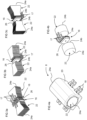
- an electrical current transducer 2 comprises a magnetic core 6, a magnetic field detector module 8, a circuit board 10 and a primary conductor 4 for carrying a primary current to be measured by the electrical current transducer 2.
- the magnetic core 6 has a general U shape comprising an end branch 14a and lateral branches 14b extending from ends of the end branch 14a to respective free ends 14c.
- the lateral branches 14b are substantially parallel to each other.
- the lateral branches are substantially orthogonal to the end branch 14a.
- the magnetic field detector module 8 is positioned between the lateral branches 14b and extends across the whole width of a gap formed between the lateral branches 14b.
- the magnetic core 6 and magnetic field detector module 8 surround a passage 12 through which the primary conductor 4 extends.
- the primary conductor 4 may be in the form of a rigid bar shaped conductor.
- the primary conductor 4 may comprise other configurations for instance in the form of a dielectric material supporting one or more conductors thereon, for instance in a form of a circuit board having a primary conductor printed or otherwise positioned thereon.
- the primary conductor bar has a rectangular shape, other profiles such as square, polygonal, elliptical, circular and irregular bar shapes may be provided.
- the primary conductor bar 4 may have a substantially constant cross section over the length of the transducer or may have a non-constant cross section, for instance a smaller width along a section extending through the passage 12 formed by the magnetic core 6.
- Ends of the conductor bus bar may have various configurations for interconnection to a primary conductor supplying the current to be measured.
- the primary conductor bar may also be interconnected by soldering, welding, clamping or other means to conductive tracks formed on the circuit board 10 or to connection ends of a primary conductor.
- the free ends 14c of the lateral branches 14b of the magnetic core 6 may be inserted through orifices 30 extending through the circuit board 10 between a first side 28a and a second side 28b of the circuit board.
- the primary conductor 4 is positioned adjacent the first side of the circuit board 10, and the magnetic field detector module 8 is mounted on the second side 28b of the circuit board 10.
- the free ends 14c of the lateral branches 14b of the magnetic core 6 extend through the orifices 30 to a height H from the second side 28b, the height being sufficient for positioning the magnetic field detector module 8 between the lateral branches 14b.
- the magnetic field detector module comprises connection terminals 18 that interconnect to conductive circuit traces formed on the circuit board 10 the circuit traces are interconnected to control electronics of an electrical device connected to the primary conductor 4 in which the current to be measured flows.
- the primary conductor 4 is positioned facing the first side 28a of the circuit board 10, and the magnetic field detector module 8 is positioned principally on the first side 28a.
- the magnetic field detector module is mounted on the first side 28a, the magnetic core 6 being mounted over both the primary conductor 4 and the magnetic field detector module 6 on the first side 28a of the circuit board.
- the circuit board 10 comprises an orifice 32 for the magnetic field detector module inserted through the circuit board from the second side 28b.
- the magnetic core 6 is made of a soft magnetic material as per se well known in the field of magnetic cores for current transducers, and forms a path of low magnetic resistance to capture the magnetic flux generated by the primary current flowing in the primary conductor 4.
- the magnetic field detector module 8 is magnetically coupled to the lateral branches of the magnetic core.
- the magnetic field detector module 8 comprises at least one magnetic field sensing cell 16, a pair of magnetic concentrators 22 arranged in mirror opposition forming a magnetic field gap 26 therebetween in which the one or more sensing cells 16 is/are positioned, and an insulating body 20 supporting the magnetic concentrators 22 and sensing cell(s) 16.
- Each magnetic concentrator extends from a core branch end 24a adjacent respective lateral branches 14b, either in direct contact with the lateral branches 14b or in close proximity thereto, to a detector end 24b forming a face of the magnetic field gap 26.
- Magnetic concentrators 22 thus concentrate the magnetic flux circulating in the U shaped magnetic core through the magnetic field gap 26.
- the magnetic concentrators may be made of a ferrite material with a high magnetic permeability the geometry of the ferrite material being selected such that the flux density inside the ferrite is less than a half the saturation flux density of the material. This allows the ferrite properties to be preserved up to a temperature exceeding half of its Curie temperature. In an advantageous embodiment, the ferrite properties are preserved up to a temperature of at least 120 degrees centigrade preferably up to 125 degrees centigrade.
- the magnetic concentrators 22 may be formed of an iron silicon material FeSi that may be formed of stamped metal sheets, a plurality being stacked to form a laminated structure. Laminated structures are per se well known in the art of magnetic armatures.
- the core branch end 24a has a surface area facing the lateral branch that is greater than a surface area of the detector end 24b facing the magnetic field gap. This allows the magnetic field detector module 8 to concentrate magnetic flux through the sensing cell(s) 16 positioned in the magnetic field gap 26 while at the same time reducing the risk of saturation in the magnetic core, and in particular at the interfaces between the magnetic core 6 and the magnetic concentrators 22.
- the ratio of the surface area A b of the detector end face 24b over the surface area A a of the core branch interface 24a is preferably less than 80% ( A b / A a ⁇ 80% ), preferably in a range of 50 to 80 % ( 50% ⁇ A b / A a ⁇ 80% ).
- the sensing cell 16 may advantageously be in a form of an application specific integrated circuit (ASIC) having terminals 17 for connection to conductive circuit traces on the circuit board 10 for power and signal transmission.
- ASIC application specific integrated circuit
- the ASIC may comprise a Hall effect detector, however the sensing cell may comprise other per se well known magnetic field detectors.
- the terminals 17 either form connection terminals for direct connection to the circuit board 10 or may be connected to terminals 18 supported in an insulating body 20 of the magnetic field detector module 8.
- the terminals 18 may advantageously be formed from a stamped lead frame and supported within the insulating body 20.
- two sensing cells 16 may be adjacently mounted in the magnetic field gap. This allows to provide a redundant magnetic field detector for applications requiring increased safety or reliability.
- the sensing cells may advantageously be identical and mounted in mirror image symmetry.
- the two sensing cells may also be connected to control electronics in a manner to sum or to average the output signal of the sensing cells.
- the insulating body may for instance comprise a polymer material overmolded over the magnetic concentrators 22 and the sensing cell 16.
- the insulating body 20 may also be formed of one or more housing parts that are assembled and fixed around the magnetic concentrator and sensing cell(s).
- the insulating body 20 does not cover the core branch ends 24a of the pair of opposed magnetic concentrators 22 such that the core branch ends may be in direct contact with the inner sides of the lateral branches 14b of the magnetic core 6.
- the small magnetic field gap formed therebetween thus improves magnetic flux conduction between the magnetic core and the magnetic field concentrators.
- this direct contact may also provide electrical interconnection between the magnetic core 6 and the magnetic concentrators 22 to provide a ground connection for the magnetic field concentrators 22 by interconnecting the magnetic core 6 to conductive circuit traces on the circuit board connected to electrical ground.
- the lateral branches 14b may advantageously be inserted through the orifices 30 and soldered, welded, bonded by adhesive or fixed by mechanical means to the circuit board.
- conductive pads or circuit traces lining the orifices 30 may be provided for mechanical and optionally electric coupling of the magnet core 6 to the circuit board 10.
- other interconnection means would be possible within the scope of the invention, for instance by providing elastic contacts on the circuit board for clamping the lateral branches of the magnetic core or other mechanical fixing means such as with screws or rivets.
- the magnetic field detector module comprising magnetic field concentrators and a magnetic sensing cell held in an insulating body as a separate and single unit mountable between lateral branches of a simple U shaped magnetic core, allows easy assembly and direct integration of the current transducer on a circuit board and around a primary conductor bar, as well as a compact configuration.
- the separately formed magnetic field detector module 8 increases flexibility of the configuration, in particular for placing the primary conductor bar on a same side of the circuit board or on an opposite side of the circuit board with respect to the magnetic field detector module.
- the formation of the magnetic field gap between magnetic field concentrators within which the sensing cell 16 is positioned, held in an insulating body, in particular an insulating body 20 that may be overmolded over the aforesaid components, ensures an accurate and stable magnetic field gap while allowing great flexibility in assembly around a primary conductor bar in a cost effective manner.
- the invention thus facilitates assembly and increases mounting possibilities while ensuring accurate and stable measurement in a robust configuration.
Landscapes
- Physics & Mathematics (AREA)
- General Physics & Mathematics (AREA)
- Engineering & Computer Science (AREA)
- Power Engineering (AREA)
- Microelectronics & Electronic Packaging (AREA)
- Measuring Instrument Details And Bridges, And Automatic Balancing Devices (AREA)
Claims (15)
- Elektrischer Stromwandler (2), der einen Magnetkern (6) und ein Magnetfeld-Detektormodul (8) umfasst, wobei der Magnetkern und das Magnetfeld-Detektormodul jeweils eine einzelne Einheit bilden, die trennbar um einen Hauptleiter (4) und an eine Leiterplatte (10) montierbar ist, wobei der Magnetkern eine allgemeine Form eines U aufweist, die einen Endschenkel (14a) und seitliche Schenkel (14b) umfasst, die sich von dem Endschenkel zu jeweiligen freien Enden (14c) erstrecken, wobei das Magnetfeld-Detektormodul zwischen den seitlichen Schenkeln positioniert ist und sich über eine gesamte Breite eines Spalts erstreckt, der derart zwischen den seitlichen Schenkeln gebildet ist, dass das Magnetfeld-Detektormodul entgegengesetzte innere Seiten der seitlichen Schenkel kontaktiert, wobei die inneren Seiten im Wesentlichen orthogonal zur Leiterplatte angeordnet sind, wobei das Magnetfeld-Detektormodul mindestens eine Magnetfeld-Sensorzelle (16), ein Paar Magnetkonzentratoren (22), die spiegelverkehrt angeordnet sind und einen Magnetfeldspalt (26) dazwischen bilden, wobei die mindestens eine Sensorzelle im Inneren des Magnetfeldspalts positioniert ist, und einen isolierenden Körper (20) umfasst, der die Magnetkonzentratoren und mindestens eine Sensorzelle stützt.
- Stromwandler nach dem vorhergehenden Anspruch, wobei die seitlichen Schenkel des Magnetkerns im Wesentlichen parallel zueinander sind.
- Stromwandler nach einem der vorhergehenden Ansprüche, wobei die seitlichen Schenkel im Wesentlichen orthogonal zum Endschenkel des Magnetkerns sind.
- Stromwandler nach einem der vorhergehenden Ansprüche, wobei jeder Magnetkonzentrator sich von einem Kernschenkelende (24a), das benachbart zu einem jeweiligen seitlichen Schenkel ist, zu einem Detektorende (24b) erstreckt, das eine Seite des Magnetfeldspalts bildet, wobei ein Verhältnis eines Flächeninhalts Ab des Detektorendes, geteilt durch einen Flächeninhalt Aa des Kernschenkelendes, kleiner als 80 % (Ab /Aa < 80 %) ist, vorzugsweise in einem Bereich von 50 % bis 80 % (50 % < Ab /Aa < 80 %) liegt.
- Stromwandler nach einem der vorhergehenden Ansprüche, wobei jeder Magnetkonzentrator sich von einem Kernschenkelende (24a) benachbart zu einem jeweiligen seitlichen Schenkel zu einem Detektorende (24b) erstreckt, das eine Seite des Magnetfeldspalts bildet, wobei das Kernschenkelende in direktem Kontakt mit einem entsprechenden seitlichen Schenkel des Magnetkerns steht.
- Stromwandler nach dem vorhergehenden Anspruch, wobei der direkte Kontakt eine elektrische Zusammenschaltung zwischen den Magnetfeldkonzentratoren und dem Magnetkern bereitstellt.
- Stromwandler nach einem der vorhergehenden Ansprüche, wobei die seitlichen Schenkel des Magnetkerns durch Öffnungen (30) in der Leiterplatte eingesetzt sind.
- Stromwandler nach dem vorhergehenden Anspruch, wobei die seitlichen Schenkel des Magnetkerns durch Löten an eine Metallschicht auf den Rändern der Öffnungen der Leiterplatte gekoppelt sind.
- Stromwandler nach einem der vorhergehenden Ansprüche, wobei die mindestens eine Sensorzelle in einer Form einer anwendungsspezifischen integrierten Schaltung (ASIC) vorliegt, zum Beispiel einen Hall-Effekt-Detektor umfasst, mit Anschlüssen (17) zur Leistungs- und Signalübertragung, wobei die Anschlüsse (17) entweder Verbindungsanschlüsse zur direkten Verbindung mit der Leiterplatte bilden oder mit Anschlüssen (18) verbunden sind, die aus einem gestanzten Leiterrahmen gebildet sind und innerhalb des isolierenden Körpers gestützt werden.
- Stromwandler nach einem der vorhergehenden Ansprüche, wobei der isolierende Körper ein Polymermaterial umfasst, das über den Magnetkonzentratoren und der mindestens einen Sensorzelle überspritzt ist.
- Stromwandler nach einem der vorhergehenden Ansprüche, wobei der isolierende Körper Kernschenkelenden (24a) des Paares entgegengesetzter Magnetkonzentratoren nicht bedeckt, derart dass die Kernschenkelenden in direktem Kontakt mit inneren Seiten der seitlichen Schenkel des Magnetkerns stehen können.
- Stromwandler nach einem der vorhergehenden Ansprüche, der zwei der Sensorzellen umfasst, die benachbart in dem Magnetfeldspalt montiert sind.
- Verfahren zum Zusammenbauen eines elektrischen Stromwandlers (2), der einen Magnetkern (6), der eine allgemeine Form eines U aufweist, die einen Endschenkel (14a) und seitliche Schenkel (14b) umfasst, die sich vom Endschenkel zu jeweiligen freien Enden (14c) erstrecken, eine Hautleiterschiene (4), eine Leiterplatte (10), die Öffnungen (30) zum Aufnehmen der seitlichen Schenkel umfasst, und ein Magnetfeld-Detektormodul (8) umfasst, das mindestens eine Magnetfeld-Sensorzelle (16), ein Paar Magnetkonzentratoren (22), die spiegelverkehrt angeordnet sind und einen Magnetfeldspalt (26) dazwischen bilden, in dem die mindestens eine Sensorzelle positioniert wird, einen isolierenden Körper (20), der die Magnetkonzentratoren und Sensorzelle/n stützt, und Anschlüsse (18) zur Verbindung mit der Leiterplatte umfasst, wobei das Verfahren Folgendes umfasst: (a) Montieren des Magnetfeld-Detektormoduls an der Leiterplatte, (b) Montieren des Magnetkerns um den Hauptleiter und Einsetzen der freien Enden des Magnetkerns durch die Öffnungen (30) der Leiterplatte, wodurch das Magnetfeld-Detektormodul zwischen den seitlichen Schenkeln positioniert wird und sich über eine gesamte Breite eines Spalts erstreckt, der zwischen den seitlichen Schenkeln gebildet ist, derart dass das Magnetfeld-Detektormodul entgegengesetzte innere Seiten der seitlichen Schenkel kontaktiert, wobei die inneren Seiten im Wesentlichen orthogonal zur Leiterplatte angeordnet sind.
- Verfahren nach dem vorhergehenden Anspruch, wobei der Hauptleiter benachbart zu einer ersten magnetischen Seite (28a) der Leiterplatte positioniert ist und das Magnetfeld-Detektormodul auf einer zweiten Seite (28b) der Leiterplatte montiert ist.
- Verfahren nach dem vorhergehenden Anspruch 13, wobei das Magnetfeld-Detektormodul hauptsächlich auf einer ersten Seite (28a) der Leiterplatte montiert ist und der Hauptleiter benachbart zu dem Magnetfeld-Detektormodul auf der ersten Seite (28a) der Leiterplatte positioniert ist.
Applications Claiming Priority (2)
| Application Number | Priority Date | Filing Date | Title |
|---|---|---|---|
| EP19154562.3A EP3690450A1 (de) | 2019-01-30 | 2019-01-30 | Stromwandler mit magnetfelddetektormodul |
| PCT/EP2020/051956 WO2020157019A1 (en) | 2019-01-30 | 2020-01-27 | Current transducer with magnetic field detector module |
Publications (3)
| Publication Number | Publication Date |
|---|---|
| EP3918347A1 EP3918347A1 (de) | 2021-12-08 |
| EP3918347B1 true EP3918347B1 (de) | 2025-04-02 |
| EP3918347C0 EP3918347C0 (de) | 2025-04-02 |
Family
ID=65268841
Family Applications (2)
| Application Number | Title | Priority Date | Filing Date |
|---|---|---|---|
| EP19154562.3A Withdrawn EP3690450A1 (de) | 2019-01-30 | 2019-01-30 | Stromwandler mit magnetfelddetektormodul |
| EP20702764.0A Active EP3918347B1 (de) | 2019-01-30 | 2020-01-27 | Stromwandler mit magnetfelddetektormodul |
Family Applications Before (1)
| Application Number | Title | Priority Date | Filing Date |
|---|---|---|---|
| EP19154562.3A Withdrawn EP3690450A1 (de) | 2019-01-30 | 2019-01-30 | Stromwandler mit magnetfelddetektormodul |
Country Status (6)
| Country | Link |
|---|---|
| US (1) | US12078661B2 (de) |
| EP (2) | EP3690450A1 (de) |
| JP (1) | JP7225420B2 (de) |
| KR (1) | KR102644470B1 (de) |
| CN (1) | CN113366322B (de) |
| WO (1) | WO2020157019A1 (de) |
Families Citing this family (7)
| Publication number | Priority date | Publication date | Assignee | Title |
|---|---|---|---|---|
| DE102019214416A1 (de) * | 2019-09-23 | 2021-03-25 | Aktiebolaget Skf | Kabellose Maschinenzustandsüberwachungsvorrichtung |
| JP6914395B1 (ja) * | 2020-04-23 | 2021-08-04 | 三菱電機株式会社 | 電力変換装置 |
| EP4235193B1 (de) * | 2022-02-28 | 2024-05-01 | LEM International SA | Magnetfelddetektormodul |
| CN119563113A (zh) * | 2022-08-10 | 2025-03-04 | 阿尔卑斯阿尔派株式会社 | 电流传感器 |
| DE112023006465T5 (de) * | 2023-06-06 | 2026-03-26 | Mitsubishi Electric Mobility Corporation | Leistungsumwandlungsvorrichtung und elektrofahrzeug |
| WO2025059178A1 (en) * | 2023-09-12 | 2025-03-20 | Fluke Corporation | Transducer having magnetic flux concentrator |
| KR102878137B1 (ko) * | 2024-03-26 | 2025-10-30 | 아사히 가세이 일렉트로닉스 가부시끼가이샤 | 전류 센서 및 전자 디바이스 |
Family Cites Families (28)
| Publication number | Priority date | Publication date | Assignee | Title |
|---|---|---|---|---|
| JPH0552872A (ja) * | 1991-08-26 | 1993-03-02 | Mitsubishi Electric Corp | 実効値レベル検出装置 |
| JPH09129944A (ja) * | 1995-10-31 | 1997-05-16 | Hitachi Ltd | 磁電変換素子 |
| JPH09127159A (ja) * | 1995-11-02 | 1997-05-16 | Hinode Denki Seisakusho:Kk | 電流検出器 |
| JPH11261131A (ja) * | 1998-03-13 | 1999-09-24 | Yazaki Corp | 磁電変換素子及びその製造方法 |
| CN100516907C (zh) * | 2003-07-25 | 2009-07-22 | 功率测量有限公司 | 用于高压线路的由体电容电场激励的装置 |
| CN100520252C (zh) | 2004-12-28 | 2009-07-29 | 利勃海尔-家用电器奥克森豪森有限责任公司 | 冷藏和冷冻单元 |
| FR2891917B1 (fr) * | 2005-10-07 | 2008-01-11 | Billanco | Capteurs de champ magnetique et de courant, procede de commande et noyau magnetique pour ces capteurs |
| EP1811311B1 (de) * | 2006-01-19 | 2016-08-31 | Melexis Technologies NV | Vorrichtung zur Strommessung |
| US20070279053A1 (en) * | 2006-05-12 | 2007-12-06 | Taylor William P | Integrated current sensor |
| EP2073025B1 (de) * | 2007-12-18 | 2010-11-03 | Liaisons Electroniques-Mecaniques Lem S.A. | Stromsensor mit laminiertem Magnetkern |
| JP5666192B2 (ja) * | 2010-08-03 | 2015-02-12 | 愛三工業株式会社 | 電流センサ |
| EP2423693B1 (de) * | 2010-08-24 | 2020-02-26 | LEM International SA | Ringförmiger Stromwandler |
| CH705027A1 (de) * | 2011-05-30 | 2012-11-30 | Melexis Technologies Nv | Vorrichtung zur Messung eines durch ein elektrisches Kabel fliessenden Stroms. |
| EP2587268A1 (de) * | 2011-10-26 | 2013-05-01 | LEM Intellectual Property SA | Elektrischer Stromwandler |
| JP2013148512A (ja) * | 2012-01-20 | 2013-08-01 | Aisin Seiki Co Ltd | 電流センサ |
| EP2660611A1 (de) * | 2012-04-30 | 2013-11-06 | LEM Intellectual Property SA | Elektrisches Stromtransformatormodul |
| EP2682762A1 (de) * | 2012-07-06 | 2014-01-08 | Senis AG | Stromwandler zum Messen von Strom, magnetischer Wandler und Stromleckagenerkennungssystem und -verfahren |
| JP6059476B2 (ja) * | 2012-09-20 | 2017-01-11 | 富士通コンポーネント株式会社 | 電力センサ |
| CN103185435A (zh) | 2013-03-18 | 2013-07-03 | 海尔集团公司 | 直冷冰箱 |
| EP2924451B1 (de) * | 2014-03-24 | 2019-01-09 | LEM Intellectual Property SA | Stromwandler |
| EP2942631B1 (de) * | 2014-04-28 | 2024-03-06 | TYCO ELECTRONICS AMP KOREA Co., Ltd. | Hybridstromsensoranordnung |
| JP2016099320A (ja) * | 2014-11-26 | 2016-05-30 | アイシン精機株式会社 | 電流センサ |
| EP3093672B1 (de) | 2015-05-09 | 2020-08-12 | LEM International SA | Stromwandler mit integrierter primärer leiterschiene |
| US9810722B2 (en) | 2015-09-23 | 2017-11-07 | Faraday & Future Inc. | Dual gap current sensor for multi phase conduction system |
| EP3159705A1 (de) * | 2015-10-23 | 2017-04-26 | LEM Intellectual Property SA | Stromwandler mit integriertem primärem leiter |
| EP3306325B1 (de) * | 2016-10-05 | 2021-07-21 | Fico Triad, S.A. | Strommessvorrichtung |
| DE112017007752B4 (de) * | 2017-07-17 | 2025-02-13 | Maglab Ag | Kombinationsstromerfassungseinrichtung |
| US11067606B2 (en) * | 2018-08-21 | 2021-07-20 | Cyntec Co., Ltd. | Current sensing module |
-
2019
- 2019-01-30 EP EP19154562.3A patent/EP3690450A1/de not_active Withdrawn
-
2020
- 2020-01-27 JP JP2021544380A patent/JP7225420B2/ja active Active
- 2020-01-27 WO PCT/EP2020/051956 patent/WO2020157019A1/en not_active Ceased
- 2020-01-27 CN CN202080011383.6A patent/CN113366322B/zh active Active
- 2020-01-27 US US17/426,393 patent/US12078661B2/en active Active
- 2020-01-27 KR KR1020217025656A patent/KR102644470B1/ko active Active
- 2020-01-27 EP EP20702764.0A patent/EP3918347B1/de active Active
Also Published As
| Publication number | Publication date |
|---|---|
| KR20210116535A (ko) | 2021-09-27 |
| EP3918347A1 (de) | 2021-12-08 |
| CN113366322B (zh) | 2024-05-14 |
| JP2022519060A (ja) | 2022-03-18 |
| EP3690450A1 (de) | 2020-08-05 |
| US12078661B2 (en) | 2024-09-03 |
| WO2020157019A1 (en) | 2020-08-06 |
| US20220099708A1 (en) | 2022-03-31 |
| JP7225420B2 (ja) | 2023-02-20 |
| CN113366322A (zh) | 2021-09-07 |
| KR102644470B1 (ko) | 2024-03-07 |
| EP3918347C0 (de) | 2025-04-02 |
Similar Documents
| Publication | Publication Date | Title |
|---|---|---|
| EP3918347B1 (de) | Stromwandler mit magnetfelddetektormodul | |
| EP4212887B1 (de) | Stromwandler | |
| EP2732294B1 (de) | Stromsensor mit geerdetem magnetkern | |
| US9714959B2 (en) | Current sensor and electronic device incorporating the same | |
| EP2835655B1 (de) | Stromsensor | |
| EP2845016B1 (de) | Elektrisches stromtransformatormodul | |
| US6769166B1 (en) | Method of making an electrical current sensor | |
| JP2009270910A (ja) | 電流検出装置 | |
| US11994538B2 (en) | Current transducer with magnetic core on primary conductor bar | |
| JP4891217B2 (ja) | 電流センサ | |
| WO2018010746A1 (en) | Electricity meter | |
| CN112272853A (zh) | 分流电阻器以及分流电阻器的安装结构 | |
| JP2012058080A (ja) | 電流検出装置 | |
| JP2012141262A (ja) | 電流検出装置 | |
| CN120826613A (zh) | 具有差分磁场换能器的电流传感器 | |
| EP4703734A1 (de) | Kernloser stromwandler | |
| JP2005147755A (ja) | 電流検出装置 | |
| WO2025131825A1 (en) | Coreless current transducer | |
| JP2017199474A (ja) | 電流センサ付き端子台 | |
| JP2013024571A (ja) | バスバー |
Legal Events
| Date | Code | Title | Description |
|---|---|---|---|
| STAA | Information on the status of an ep patent application or granted ep patent |
Free format text: STATUS: UNKNOWN |
|
| STAA | Information on the status of an ep patent application or granted ep patent |
Free format text: STATUS: THE INTERNATIONAL PUBLICATION HAS BEEN MADE |
|
| PUAI | Public reference made under article 153(3) epc to a published international application that has entered the european phase |
Free format text: ORIGINAL CODE: 0009012 |
|
| STAA | Information on the status of an ep patent application or granted ep patent |
Free format text: STATUS: REQUEST FOR EXAMINATION WAS MADE |
|
| 17P | Request for examination filed |
Effective date: 20210802 |
|
| AK | Designated contracting states |
Kind code of ref document: A1 Designated state(s): AL AT BE BG CH CY CZ DE DK EE ES FI FR GB GR HR HU IE IS IT LI LT LU LV MC MK MT NL NO PL PT RO RS SE SI SK SM TR |
|
| DAV | Request for validation of the european patent (deleted) | ||
| DAX | Request for extension of the european patent (deleted) | ||
| RAP3 | Party data changed (applicant data changed or rights of an application transferred) |
Owner name: LEM INTERNATIONAL SA |
|
| STAA | Information on the status of an ep patent application or granted ep patent |
Free format text: STATUS: EXAMINATION IS IN PROGRESS |
|
| 17Q | First examination report despatched |
Effective date: 20240103 |
|
| GRAP | Despatch of communication of intention to grant a patent |
Free format text: ORIGINAL CODE: EPIDOSNIGR1 |
|
| STAA | Information on the status of an ep patent application or granted ep patent |
Free format text: STATUS: GRANT OF PATENT IS INTENDED |
|
| INTG | Intention to grant announced |
Effective date: 20250113 |
|
| GRAS | Grant fee paid |
Free format text: ORIGINAL CODE: EPIDOSNIGR3 |
|
| GRAA | (expected) grant |
Free format text: ORIGINAL CODE: 0009210 |
|
| STAA | Information on the status of an ep patent application or granted ep patent |
Free format text: STATUS: THE PATENT HAS BEEN GRANTED |
|
| AK | Designated contracting states |
Kind code of ref document: B1 Designated state(s): AL AT BE BG CH CY CZ DE DK EE ES FI FR GB GR HR HU IE IS IT LI LT LU LV MC MK MT NL NO PL PT RO RS SE SI SK SM TR |
|
| REG | Reference to a national code |
Ref country code: GB Ref legal event code: FG4D |
|
| REG | Reference to a national code |
Ref country code: CH Ref legal event code: EP |
|
| REG | Reference to a national code |
Ref country code: DE Ref legal event code: R096 Ref document number: 602020048663 Country of ref document: DE |
|
| REG | Reference to a national code |
Ref country code: IE Ref legal event code: FG4D |
|
| U01 | Request for unitary effect filed |
Effective date: 20250402 |
|
| U07 | Unitary effect registered |
Designated state(s): AT BE BG DE DK EE FI FR IT LT LU LV MT NL PT RO SE SI Effective date: 20250409 |
|
| PG25 | Lapsed in a contracting state [announced via postgrant information from national office to epo] |
Ref country code: ES Free format text: LAPSE BECAUSE OF FAILURE TO SUBMIT A TRANSLATION OF THE DESCRIPTION OR TO PAY THE FEE WITHIN THE PRESCRIBED TIME-LIMIT Effective date: 20250402 |
|
| PG25 | Lapsed in a contracting state [announced via postgrant information from national office to epo] |
Ref country code: NO Free format text: LAPSE BECAUSE OF FAILURE TO SUBMIT A TRANSLATION OF THE DESCRIPTION OR TO PAY THE FEE WITHIN THE PRESCRIBED TIME-LIMIT Effective date: 20250702 Ref country code: GR Free format text: LAPSE BECAUSE OF FAILURE TO SUBMIT A TRANSLATION OF THE DESCRIPTION OR TO PAY THE FEE WITHIN THE PRESCRIBED TIME-LIMIT Effective date: 20250703 |
|
| PG25 | Lapsed in a contracting state [announced via postgrant information from national office to epo] |
Ref country code: PL Free format text: LAPSE BECAUSE OF FAILURE TO SUBMIT A TRANSLATION OF THE DESCRIPTION OR TO PAY THE FEE WITHIN THE PRESCRIBED TIME-LIMIT Effective date: 20250402 |
|
| PG25 | Lapsed in a contracting state [announced via postgrant information from national office to epo] |
Ref country code: HR Free format text: LAPSE BECAUSE OF FAILURE TO SUBMIT A TRANSLATION OF THE DESCRIPTION OR TO PAY THE FEE WITHIN THE PRESCRIBED TIME-LIMIT Effective date: 20250402 |
|
| PG25 | Lapsed in a contracting state [announced via postgrant information from national office to epo] |
Ref country code: RS Free format text: LAPSE BECAUSE OF FAILURE TO SUBMIT A TRANSLATION OF THE DESCRIPTION OR TO PAY THE FEE WITHIN THE PRESCRIBED TIME-LIMIT Effective date: 20250702 |
|
| PG25 | Lapsed in a contracting state [announced via postgrant information from national office to epo] |
Ref country code: IS Free format text: LAPSE BECAUSE OF FAILURE TO SUBMIT A TRANSLATION OF THE DESCRIPTION OR TO PAY THE FEE WITHIN THE PRESCRIBED TIME-LIMIT Effective date: 20250802 |
|
| PG25 | Lapsed in a contracting state [announced via postgrant information from national office to epo] |
Ref country code: SM Free format text: LAPSE BECAUSE OF FAILURE TO SUBMIT A TRANSLATION OF THE DESCRIPTION OR TO PAY THE FEE WITHIN THE PRESCRIBED TIME-LIMIT Effective date: 20250402 |
|
| PG25 | Lapsed in a contracting state [announced via postgrant information from national office to epo] |
Ref country code: CZ Free format text: LAPSE BECAUSE OF FAILURE TO SUBMIT A TRANSLATION OF THE DESCRIPTION OR TO PAY THE FEE WITHIN THE PRESCRIBED TIME-LIMIT Effective date: 20250402 |
|
| U20 | Renewal fee for the european patent with unitary effect paid |
Year of fee payment: 7 Effective date: 20251218 |
|
| PG25 | Lapsed in a contracting state [announced via postgrant information from national office to epo] |
Ref country code: SK Free format text: LAPSE BECAUSE OF FAILURE TO SUBMIT A TRANSLATION OF THE DESCRIPTION OR TO PAY THE FEE WITHIN THE PRESCRIBED TIME-LIMIT Effective date: 20250402 |
|
| PLBE | No opposition filed within time limit |
Free format text: ORIGINAL CODE: 0009261 |
|
| STAA | Information on the status of an ep patent application or granted ep patent |
Free format text: STATUS: NO OPPOSITION FILED WITHIN TIME LIMIT |
|
| REG | Reference to a national code |
Ref country code: CH Ref legal event code: L10 Free format text: ST27 STATUS EVENT CODE: U-0-0-L10-L00 (AS PROVIDED BY THE NATIONAL OFFICE) Effective date: 20260211 |
|
| 26N | No opposition filed |
Effective date: 20260105 |