EP3916751A1 - Lichtbogenlöschdüse und lastschalter mit der lichtbogenlöschdüse - Google Patents
Lichtbogenlöschdüse und lastschalter mit der lichtbogenlöschdüse Download PDFInfo
- Publication number
- EP3916751A1 EP3916751A1 EP21176393.3A EP21176393A EP3916751A1 EP 3916751 A1 EP3916751 A1 EP 3916751A1 EP 21176393 A EP21176393 A EP 21176393A EP 3916751 A1 EP3916751 A1 EP 3916751A1
- Authority
- EP
- European Patent Office
- Prior art keywords
- rotary blade
- arc
- arc extinguishing
- load switch
- nozzle
- Prior art date
- Legal status (The legal status is an assumption and is not a legal conclusion. Google has not performed a legal analysis and makes no representation as to the accuracy of the status listed.)
- Granted
Links
Images



Classifications
-
- H—ELECTRICITY
- H01—ELECTRIC ELEMENTS
- H01H—ELECTRIC SWITCHES; RELAYS; SELECTORS; EMERGENCY PROTECTIVE DEVICES
- H01H33/00—High-tension or heavy-current switches with arc-extinguishing or arc-preventing means
- H01H33/70—Switches with separate means for directing, obtaining, or increasing flow of arc-extinguishing fluid
- H01H33/7015—Switches with separate means for directing, obtaining, or increasing flow of arc-extinguishing fluid characterised by flow directing elements associated with contacts
-
- H—ELECTRICITY
- H01—ELECTRIC ELEMENTS
- H01H—ELECTRIC SWITCHES; RELAYS; SELECTORS; EMERGENCY PROTECTIVE DEVICES
- H01H1/00—Contacts
- H01H1/12—Contacts characterised by the manner in which co-operating contacts engage
- H01H1/36—Contacts characterised by the manner in which co-operating contacts engage by sliding
- H01H1/42—Knife-and-clip contacts
-
- H—ELECTRICITY
- H01—ELECTRIC ELEMENTS
- H01H—ELECTRIC SWITCHES; RELAYS; SELECTORS; EMERGENCY PROTECTIVE DEVICES
- H01H31/00—Air-break switches for high tension without arc-extinguishing or arc-preventing means
- H01H31/003—Earthing switches
-
- H—ELECTRICITY
- H01—ELECTRIC ELEMENTS
- H01H—ELECTRIC SWITCHES; RELAYS; SELECTORS; EMERGENCY PROTECTIVE DEVICES
- H01H33/00—High-tension or heavy-current switches with arc-extinguishing or arc-preventing means
- H01H33/70—Switches with separate means for directing, obtaining, or increasing flow of arc-extinguishing fluid
- H01H33/88—Switches with separate means for directing, obtaining, or increasing flow of arc-extinguishing fluid the flow of arc-extinguishing fluid being produced or increased by movement of pistons or other pressure-producing parts
- H01H33/886—Switches with separate means for directing, obtaining, or increasing flow of arc-extinguishing fluid the flow of arc-extinguishing fluid being produced or increased by movement of pistons or other pressure-producing parts by movement of rotating pistons
-
- H—ELECTRICITY
- H01—ELECTRIC ELEMENTS
- H01H—ELECTRIC SWITCHES; RELAYS; SELECTORS; EMERGENCY PROTECTIVE DEVICES
- H01H33/00—High-tension or heavy-current switches with arc-extinguishing or arc-preventing means
- H01H33/70—Switches with separate means for directing, obtaining, or increasing flow of arc-extinguishing fluid
- H01H33/88—Switches with separate means for directing, obtaining, or increasing flow of arc-extinguishing fluid the flow of arc-extinguishing fluid being produced or increased by movement of pistons or other pressure-producing parts
- H01H33/90—Switches with separate means for directing, obtaining, or increasing flow of arc-extinguishing fluid the flow of arc-extinguishing fluid being produced or increased by movement of pistons or other pressure-producing parts this movement being effected by or in conjunction with the contact-operating mechanism
- H01H33/91—Switches with separate means for directing, obtaining, or increasing flow of arc-extinguishing fluid the flow of arc-extinguishing fluid being produced or increased by movement of pistons or other pressure-producing parts this movement being effected by or in conjunction with the contact-operating mechanism the arc-extinguishing fluid being air or gas
-
- H—ELECTRICITY
- H01—ELECTRIC ELEMENTS
- H01H—ELECTRIC SWITCHES; RELAYS; SELECTORS; EMERGENCY PROTECTIVE DEVICES
- H01H9/00—Details of switching devices, not covered by groups H01H1/00 - H01H7/00
- H01H9/30—Means for extinguishing or preventing arc between current-carrying parts
- H01H9/34—Stationary parts for restricting or subdividing the arc, e.g. barrier plate
- H01H9/342—Venting arrangements for arc chutes
Definitions
- the present invention relates to the technical field of electrical apparatuses, and in particular, to an arc extinguishing nozzle and a load switch having the same.
- a load switch is a switching apparatus for turning on, carrying, and cutting off current under normal conductive loop conditions or specified overload conditions, and an arc extinguishing device is disposed therein.
- a rotary pressure-operated load switch generally includes an insulating housing filled with an arc extinguishing gas and a rotary piston rotatably connected to the insulating housing and provided with an arc extinguishing nozzle thereon.
- the rotary piston compresses the arc extinguishing gas in the insulating housing to eject the compressed gas from the arc extinguishing nozzle, so as to extinguish an arc generated when the load switch is switched from an on state to an isolated state.
- the arc extinguishing nozzle in the prior art is usually simply designed as an opening formed by making a hole or a groove on the rotary piston, and a length dimension of the arc extinguishing nozzle is determined by a thickness dimension of the rotary piston.
- the rotary piston is generally designed as a thin-plate structure, and so the length of the arc extinguishing nozzle is small.
- the present invention aims to provide an arc extinguishing nozzle capable of solving at least part of the aforementioned problems.
- the present invention further aims to provide a load switch to which the improved arc extinguishing nozzle described above is applied.
- an arc extinguishing nozzle which is used for a rotary pressure-operated load switch
- the load switch comprises an insulating housing filled with an arc extinguishing gas and a rotary blade capable of pivotally rotating with respect to the insulating housing
- the load switch is capable of being in at least an on state and an isolated state according to rotation of the rotary blade
- the arc extinguishing nozzle comprises: an opening portion, configured as an opening formed on the rotary blade and extending in a direction tangential to the rotary blade; and an arc confining portion, disposed on an inner surface and/or outer surface of the rotary blade and designed as a hollow shape protruding inward and/or outward for a certain length in the direction tangential to the rotary blade, wherein the arc confining portion and the opening portion are in communication to form a nozzle channel, so that the arc extinguishing gas compressed by the rotary blade in the insulating housing
- the arc extinguishing nozzle in the present invention is provided with the arc confining portion and the opening portion that communicate with each other to form a nozzle channel, thereby greatly extending the length of the nozzle channel in the limited space of the load switch.
- the flow rate of the arc extinguishing gas flow passing through the nozzle channel is ensured within at least a certain length of the nozzle channel greater than the thickness of the rotary blade, thereby improving the arc extinguishing effect of the arc extinguishing nozzle in this embodiment and the reliability thereof.
- the arc extinguishing nozzle in the present invention is simple in structure and easy to manufacture and produce.
- the opening portion is configured as a four-sided closed opening formed on the rotary blade and extending in the direction tangential to the rotary blade.
- the opening portion is configured as a top-side-open opening formed on the rotary blade and extending in the direction tangential to the rotary blade, and a top end of the rotary blade abuts against an inner side wall of the insulating housing such that the opening portion has a four-sided closed shape.
- the arc confining portion has a four-sided closed hollow shape.
- the arc confining portion has a top-side-open hollow shape.
- the opening portion and the arc confining portion are designed as separate structures.
- the opening portion and the arc confining portion are designed to be integrally formed.
- a load switch which comprises the aforementioned arc extinguishing nozzle, wherein the load switch further comprises an upper static contact incapable of moving with respect to the insulating housing and connected to the insulating housing, and a moving contact capable of moving along with the rotary blade and connected to the rotary blade so as to be conductively connected to or separated from the upper static contact, wherein the upper static contact is configured to move away from the moving contact and along the nozzle channel when changing from a conductively connected state to a separated state with respect to the moving contact.
- an arc is generated between the moving contact and the upper static contact when they are mechanically separated, and since the upper static contact moves along the nozzle channel away from the moving contact and the nozzle channel has a certain length, at least part of an arc column of the arc generated between the upper static contact and the moving contact is confined in the nozzle channel, and meanwhile, the cold arc extinguishing gas in the insulating housing can be ejected toward the upper static contact along the nozzle channel at a high flow rate, so as to facilitate cooling and de-ionization of the arc column confined in the nozzle channel to extinguish the arc.
- the upper static contact is configured to extend along the nozzle channel from an outer side of the rotary blade so as to be conductively connected to the moving contact.
- the upper static contact is configured to extend downward from an upper side of the rotary blade so as to be conductively connected to the moving contact.
- join and "connect” and similar terms used in the present invention refer to two components being indirectly connected to each other by an intermediate layer (such as an adhesive or a solder) or an intermediate member (such as a connection member or a transition member), and also refer to two components being directly connected to each other without any intermediate layer (such as an adhesive or a solder) or any intermediate member (such as a connection member or a transition member).
- an intermediate layer such as an adhesive or a solder
- intermediate member such as a connection member or a transition member
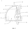
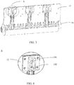
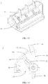
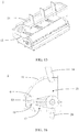
- FIG. 1 to FIG. 16 illustrate, by way of example, an arc extinguishing nozzle 10 in the present invention and a rotary pressure-operated load switch 1 to which the arc extinguishing nozzle 10 is applied.
- the load switch 1 is generally used for breaking a load current or a certain overload current.
- the arc extinguishing nozzle 10 is used for providing an ejection path of an arc extinguishing gas in the load switch 1, so as to extinguish an arc generated when the load switch 1 changes from an on state to an isolated state.
- the load switch 1 may include an insulating housing 11, a rotary blade 12, a moving contact 13, an upper static contact 14, a grounding contact 15, an insulating spindle 16, and a lower static contact 20.
- the insulating housing 11 may include a bottom plate 111, a front fan-shaped side plate and a rear fan-shaped side plate 113 disposed opposite to each other on the bottom plate 111, and an arc-shaped cover plate 112 connecting the bottom plate 111, the front fan-shaped side plate and the rear fan-shaped side plate 113.
- An inner space formed by the bottom plate 111, the front fan-shaped side plate and the rear fan-shaped side plate 113, and the arc-shaped cover plate 112 is filled with an arc extinguishing gas, for example, including but not limited to, sulfur hexafluoride, carbon dioxide, air, and other mixed arc extinguishing media.
- Two ends of the insulating spindle 16 may be mounted on the front fan-shaped side plate and the rear fan-shaped side plate 113 of the insulating housing 11 so as to rotate, in combination with an external operating mechanism and in a controlled manner, with respect to the insulating housing 11.
- the rotary blade 12 may be mounted on the insulating spindle 16 and extend toward the arc-shaped cover plate 112 to abut against the inner side of the arc-shaped cover plate 112, so as to move with respect to the insulating housing 11 along with the insulating spindle 16.
- the moving contact 13 may be connected to the insulating spindle 16, and thus may be considered connected to the rotary blade 12 via the insulating spindle 16.
- the insulating spindle 16 drives the moving contact 13 and the rotary blade 12 to synchronously rotate with respect to the insulating housing 11.
- the upper static contact 14 cannot be connected to the arc-shaped cover plate 112 by moving relative to the arc-shaped cover plate 112; the upper static contact 14 may be directly and fixedly connected to the arc-shaped cover plate 112 by means of a fastener, for example, a bolt, or may be indirectly and fixedly connected to the arc-shaped cover plate 112 by connecting to another structure that is located on the outer side of the insulating housing 11 and has no relative movement with respect to the insulating housing 11.
- the lower static contact 20 is rotatably connected to the moving contact 13 and extends through the insulating spindle 16 and the bottom plate 111.
- the grounding contact 15 may be disposed fixedly with respect to the arc-shaped cover plate 112 and pass through a side wall of the arc-shaped cover plate 112 to enter into the insulating housing 11. It can be understood that the manner of connection between the lower static contact 20 and the bottom plate 111, and that between the grounding contact 15 and the arc-shaped cover plate 112, may be similar to the manner of connection between the upper static contact 14 and the arc-shaped cover plate 112.
- the insulating spindle 16 moves in a controlled manner under the control of the external operating mechanism, so as to drive the rotary blade 12 and the moving contact 13 to rotate with respect to the insulating housing 11, that is, rotate with respect to the upper static contact 14 and the grounding contact 15.
- the moving contact 13 can switch in turn between an on state of being conductively connected to the upper static contact 14 shown in FIG. 1 and FIG. 2 or FIG. 9 and FIG. 10 , an isolated state of being separated from both the upper static contact 14 and the grounding contact 15 shown in FIG. 5 and FIG. 6 or FIG. 13 and FIG. 14 , and a grounded state of being conductively connected to the grounding contact 15 shown in FIG. 7 and FIG. 8 or FIG. 15 and FIG.
- the closed insulating housing 11 may be filled with an arc extinguishing gas, and is divided into a first chamber 17 and a second chamber 18 with variable volumes by the insulating spindle 16 and the rotary blade 12 pivotally mounted on the insulating housing 11.
- the side of the rotary blade 12 facing the interior of the insulating housing 11 is referred to as the inner side
- the first chamber 17 is the chamber that the inner side of the rotary blade 12 faces
- the second chamber 18 is the chamber that the outer side of the rotary blade 12 faces.
- the arc extinguishing nozzle 10 may include an opening portion 101 and an arc confining portion 102.
- the opening portion 101 may be configured as an opening located at the top of the rotary blade 12 and passing through the thickness of the rotary blade 12 in a direction tangential to the rotary blade 12.
- the arc confining portion 102 may be disposed on an inner surface and/or outer surface of the rotary blade 12 and designed as a hollow shape protruding inward and/or outward for a certain length, that is, disposed on a side surface of the rotary blade 12 facing the first chamber 17 and/or a side surface facing the second chamber 18 and protruding toward the first chamber 17 and/or the second chamber 18 for a certain length, so as to expand the application range thereof.
- users can make selections according to actual needs.
- a free end of the moving contact 13 may be located on the inner side of the nozzle channel or accommodated within the nozzle channel or partially accommodated within the nozzle channel.
- the arc confining portion 102 may be located on the inner surface and/or outer surface of the rotary blade 12.
- the spacing between the moving contact 13 and the rotary blade 12 may be properly increased to satisfy the desired length of the arc confining portion 102 in the tangential direction.
- the free end of the moving contact 13 occupies part of the nozzle channel, that is, the free end of the moving contact 13 is located within the opening portion 101 and/or within the arc confining portion 102.
- the free end of the moving contact 13 may be partially accommodated within the nozzle channel and partially extend inward to the inner side of the nozzle channel.
- the position of the moving contact 13 in the present invention with respect to the nozzle channel only needs to meet the requirement that, after the moving contact 13 mechanically separates from the upper static contact 14, the upper static contact 14 should travel through a length of the nozzle channel on the rotary blade 12 that is at least greater than the length of the opening portion 101.
- the shapes and configurations of the rotary blade 12, the moving contact 13, and the upper static contact 14 are not limited.
- the arc confining portion 102 is formed on the side surface of the rotary blade 12 facing the second chamber 18 and protrudes toward the second chamber 18 for a certain length, and the moving contact 13 is located on the inner side of the nozzle channel, namely, the inner side of the rotary blade 12.
- the arc confining portion 102, the opening portion 101, and the free end of the moving contact 13 are located approximately in the same direction tangential to the rotary blade 12, so that the arc confining portion 102 and the moving contact 13 are respectively located on the outer side and the inner side of the rotary blade 12 and the arc confining portion 102 extends away from the moving contact 13, and the arc confining portion 102 and the opening portion 101 may form a tangential-direction communicating nozzle channel.
- the arc confining portion 102 may be designed to extend for at least the thickness of the rotary blade 12, so that the length of the nozzle channel, namely, the length of the nozzle channel in the tangential direction, may be designed to be at least twice the thickness of the rotary blade 12 to confine and extinguish the arc between the moving contact 13 and the upper static contact 14.
- the moving contact 13 is usually configured as a pair of axially opposed blades for elastically clamping the upper static contact 14 therebetween, and then the space between the pair of blades of the moving contact 13 can communicate with the nozzle channel to form a static contact moving path.
- the insulating spindle 16 rotates with respect to the insulating housing 11 so that the moving contact 13, the rotary blade 12, the opening portion 101, and the arc confining portion 102 all rotate with respect to the upper static contact 14.
- the upper static contact 14 is first mechanically separated from the moving contact 13, and then moves away from the moving contact 13 along the nozzle channel, namely, the opening portion 101 and the arc confining portion 102. Since the nozzle channel has a certain length, the arc generated after the upper static contact 14 and the moving contact 13 are mechanically separated is confined within the opening portion 101 and the arc confining portion 102.
- the compressed arc extinguishing gas in the first chamber 17 is ejected toward the upper static contact 14 away from the moving contact 13 via the nozzle channel, thus facilitating extinguishing of the arc confined in the nozzle channel.
- the nozzle channel extends for a certain length, and thus can restrict the cross section of the ejected arc extinguishing gas flow within a certain length range. In this way, for the same arc extinguishing gas flow quantity, the flow rate of the arc extinguishing gas flow can be maintained at a high level to extinguish the arc within the certain length range, so as to improve the cut-off capability and reliability of the load switch 1 to which the nozzle channel is applied.
- the size of an opening cross section of the nozzle channel of the rotary blade 12 should be larger than the size of a cross section of the upper static contact 14 coinciding with the opening cross section to facilitate entrance and exit of the upper static contact 14.
- the minimum opening cross section of the nozzle channel may be designed to be smaller than three times the opening cross section of the upper static contact 14, so as to avoid decrease in flow rate of the arc extinguishing gas flow ejected along the nozzle channel while facilitating entrance and exit of the upper static contact 14.
- FIG. 1 to FIG. 8 illustrate, by way of example, an arc extinguishing nozzle 10 according to a first embodiment of the present invention and a load switch 1 to which the arc extinguishing nozzle 10 is applied.
- the opening portion 101 may be configured as a four-sided closed rectangular opening formed on the top of the rotary blade 12 and extending through the thickness of the rotary blade 12 in a direction tangential to the rotary blade 12.
- the arc confining portion 102 has a four-sided closed hollow rectangular shape.
- the shape of the opening cross section of the opening portion 101 and/or the arc confining portion 102 may also be configured as a trapezoid, a parallelogram, a square, or another shape.
- the opening cross sections of the opening portion 101 and the arc confining portion 102 may be configured to have the same shape and size to form a nozzle channel having a constant shape and size.
- the opening cross sections of the opening portion 101 and the arc confining portion 102 may have different shapes and sizes and only need to be configured to communicate with each other to facilitate passage of the compressed arc extinguishing gas.
- the shape of the opening cross section of the nozzle channel may be configured to be the same as or different from the shape of the cross section of the upper static contact 14.
- Such a design scheme can use a rotary blade 12 in the prior art and only the arc confining portion 102 needs to be designed, so as to greatly reduce the manufacturing cost of the nozzle channel in this embodiment and improve production efficiency.
- the length of the upper static contact 14 in the direction tangential to the rotary blade 12 may be 40 millimeters, and the length of the nozzle channel through which the upper static contact 14 passes after being separated from the moving contact 13 may be designed as any value in the range from 6 millimeters to 70 millimeters.
- the upper static contact 14 of the load switch 1 to which the arc extinguishing nozzle 10 is applied is configured, when in the conductively connected state with respect to the moving contact 13, to be connected to the top of the arc-shaped cover plate 112 via a connecting arm 19, and the upper static contact 14 is conductively connected to the moving contact 13 through the nozzle channel, namely, the arc confining portion 102 and the opening portion 101, from the outer side of the rotary blade 12, making it convenient for the upper static contact 14 to move when being separated from the moving contact 13 to avoid obstruction thereof.
- the rotary blade 12 and the arc confining portion 102 may be configured to be integrally formed; that is, the opening portion 101 and the arc confining portion 102 are integrally formed to increase the manufacturing speed of the load switch in this embodiment.
- the rotary blade 12 and the arc confining portion 102 may also be configured as separate structures.
- the manner of connection between the rotary blade 12 and the arc confining portion 102 may be designed, shown in FIG. 1 to FIG. 8 , as a bolt connection or any other connection means capable of connecting the rotary blade 12 and the arc confining portion 102 without relative movement therebetween.
- the rotary blade 12 and the arc confining portion 102 may use different materials.
- the arc confining portion 102 may use a non-metal material that is more ablation-resistant than the rotary blade 12.
- the insulating spindle 16 and the rotary blade 12 may be configured to be integrally formed or may be configured as separate structures.
- the arc confining portion 102 may be integrally formed with the aforementioned structure or may be manufactured in a separated manner and connected by a bolt or be assembled to the aforementioned structure by any other means capable of connecting the arc confining portion 102 and the aforementioned structure without relative movement therebetween.
- FIG. 9 to FIG. 16 illustrate an arc extinguishing nozzle 10 according to a second embodiment of the present invention and a load switch 1 to which the arc extinguishing nozzle 10 is applied.
- the structures are basically the same except that the arc extinguishing nozzle 10 and the upper static contact 14 have different configurations.
- the opening portion 101 may be configured as a top-side-open opening formed on the rotary blade 12 and extending through the thickness of the rotary blade 12 in a direction tangential to the rotary blade 12.
- a top end of the rotary blade 12 tightly abuts against the inner side of the arc-shaped cover plate 112 such that the opening has a four-sided closed shape.
- the rotary blade 12 may be configured to remain tightly abutted against an inner side wall of the insulating housing 11 in at least the first half of the movement from an on position to an isolated position.
- the rotary blade 12 and the inner side wall of the insulating housing 11 may be designed to be hermetically connected, or such that a minimum gap between the rotary blade 12 and the inner side wall of the insulating housing 11 is less than a predetermined gap value, for example, 3 millimeters.
- the arc confining portion 102 has a top-side-open hollow shape.
- the upper static contact 14 of the load switch 1 to which the arc extinguishing nozzle 10 is applied may be configured, when conductively connected to the moving contact 13, to extend downward from the upper side of the rotary blade 12 into the first chamber 17 so as to be conductively connected to the moving contact 13.
- the upper static contact 14 and the moving contact 13 change from the conductively connected state to the separated state, the upper static contact 14 moves through the nozzle channel, namely, the opening portion 101 and the arc confining portion 102, and the compressed arc extinguishing gas extinguishes the arc between the upper static contact 14 and the moving contact 13 along the nozzle channel.
- the opening portion 101 has a four-sided closed shape or a top-side-open shape, which may arbitrary match the four-sided closed hollow shape or top-side-open hollow shape of the arc confining portion 102 according to needs.
- the upper static contact 14 of the load switch 1 should correspondingly be arranged to extend through the arc confining portion 102 and/or the opening portion 101 from the second chamber 18 so as to be conductively connected to the moving contact 13.
- the upper static contact 14 of the load switch 1 can be arranged to extend downward from the upper side of the rotary blade 12 so as to be conductively connected to the moving contact 13 only when the opening portion 101 and the arc confining portion 102 both have the top-side-open shape.
- each embodiment does not necessarily include only one independent technical solution.
- the presentation manner of the description is merely for clearness, and those skilled in the art should regard the description as a whole, and the technical solutions in the embodiments can also be appropriately combined to form other implementations comprehensible by those skilled in the art.
Landscapes
- Circuit Breakers (AREA)
- Arc-Extinguishing Devices That Are Switches (AREA)
Applications Claiming Priority (1)
| Application Number | Priority Date | Filing Date | Title |
|---|---|---|---|
| CN202010459975.6A CN111524744B (zh) | 2020-05-27 | 2020-05-27 | 灭弧喷口及具有其的负荷开关 |
Publications (3)
| Publication Number | Publication Date |
|---|---|
| EP3916751A1 true EP3916751A1 (de) | 2021-12-01 |
| EP3916751C0 EP3916751C0 (de) | 2023-08-02 |
| EP3916751B1 EP3916751B1 (de) | 2023-08-02 |
Family
ID=71912905
Family Applications (1)
| Application Number | Title | Priority Date | Filing Date |
|---|---|---|---|
| EP21176393.3A Active EP3916751B1 (de) | 2020-05-27 | 2021-05-27 | Lichtbogenlöschdüse und lastschalter mit der lichtbogenlöschdüse |
Country Status (4)
| Country | Link |
|---|---|
| EP (1) | EP3916751B1 (de) |
| CN (1) | CN111524744B (de) |
| ES (1) | ES2957834T3 (de) |
| PT (1) | PT3916751T (de) |
Cited By (1)
| Publication number | Priority date | Publication date | Assignee | Title |
|---|---|---|---|---|
| CN119601415A (zh) * | 2024-12-27 | 2025-03-11 | 广东电网有限责任公司 | 具有灭弧功能的高压刀闸及其操作方法 |
Families Citing this family (1)
| Publication number | Priority date | Publication date | Assignee | Title |
|---|---|---|---|---|
| EP4560676A1 (de) * | 2023-11-27 | 2025-05-28 | Abb Schweiz Ag | Elektrischer strommesserschalter mit einem pufferfreigabemechanismus |
Citations (3)
| Publication number | Priority date | Publication date | Assignee | Title |
|---|---|---|---|---|
| EP0281817A1 (de) * | 1987-03-11 | 1988-09-14 | AEG Sachsenwerk GmbH | Lichtbogenlöscheinrichtung für Lastschalter |
| DE3803117A1 (de) * | 1988-02-03 | 1989-08-17 | Sachsenwerk Ag | Stromunterbrecher fuer mit einem isoliergas gefuellte, gekapselte schaltanlagen |
| JP2008071708A (ja) * | 2006-09-15 | 2008-03-27 | Chubu Electric Power Co Inc | 配電機器の消弧方法及び配電機器 |
Family Cites Families (7)
| Publication number | Priority date | Publication date | Assignee | Title |
|---|---|---|---|---|
| FR2606209B1 (fr) * | 1986-11-03 | 1994-05-20 | Merlin Et Gerin | Interrupteur rotatif multipolaire a isolement gazeux |
| US5153399A (en) * | 1990-11-06 | 1992-10-06 | G&W Electric Company | Rotary puffer switch |
| CN201655650U (zh) * | 2010-01-25 | 2010-11-24 | 刘坚钢 | 高压负荷开关 |
| CN102629530B (zh) * | 2012-03-30 | 2014-01-15 | 厦门华电开关有限公司 | 灭弧负荷开关及开关设备 |
| CN104616928B (zh) * | 2015-02-04 | 2017-06-06 | 中骏电气(厦门)有限公司 | 一种负荷开关 |
| CN207319990U (zh) * | 2017-10-29 | 2018-05-04 | 默飓电气有限公司 | 一种高压负荷开关 |
| CN107706037B (zh) * | 2017-10-29 | 2020-11-03 | 默飓电气有限公司 | 一种高压负荷开关 |
-
2020
- 2020-05-27 CN CN202010459975.6A patent/CN111524744B/zh active Active
-
2021
- 2021-05-27 ES ES21176393T patent/ES2957834T3/es active Active
- 2021-05-27 PT PT211763933T patent/PT3916751T/pt unknown
- 2021-05-27 EP EP21176393.3A patent/EP3916751B1/de active Active
Patent Citations (3)
| Publication number | Priority date | Publication date | Assignee | Title |
|---|---|---|---|---|
| EP0281817A1 (de) * | 1987-03-11 | 1988-09-14 | AEG Sachsenwerk GmbH | Lichtbogenlöscheinrichtung für Lastschalter |
| DE3803117A1 (de) * | 1988-02-03 | 1989-08-17 | Sachsenwerk Ag | Stromunterbrecher fuer mit einem isoliergas gefuellte, gekapselte schaltanlagen |
| JP2008071708A (ja) * | 2006-09-15 | 2008-03-27 | Chubu Electric Power Co Inc | 配電機器の消弧方法及び配電機器 |
Cited By (1)
| Publication number | Priority date | Publication date | Assignee | Title |
|---|---|---|---|---|
| CN119601415A (zh) * | 2024-12-27 | 2025-03-11 | 广东电网有限责任公司 | 具有灭弧功能的高压刀闸及其操作方法 |
Also Published As
| Publication number | Publication date |
|---|---|
| ES2957834T3 (es) | 2024-01-26 |
| PT3916751T (pt) | 2023-10-03 |
| EP3916751C0 (de) | 2023-08-02 |
| CN111524744B (zh) | 2023-03-31 |
| EP3916751B1 (de) | 2023-08-02 |
| CN111524744A (zh) | 2020-08-11 |
Similar Documents
| Publication | Publication Date | Title |
|---|---|---|
| US4562323A (en) | Switch device having an insulating screen inserted between the contacts during breaking and means for shearing the arc between this screen and an insulating wall | |
| KR100439389B1 (ko) | 회로 차단기 | |
| CN101064226B (zh) | 吹气型气体断路器 | |
| EP3916751B1 (de) | Lichtbogenlöschdüse und lastschalter mit der lichtbogenlöschdüse | |
| EP3631829B1 (de) | Elektrisches kontaktsystem | |
| CN112017908A (zh) | 一种分断器件 | |
| CN112289635B (zh) | 一种真空断路器 | |
| US4218597A (en) | Gas-blast type circuit interrupter | |
| CN220020919U (zh) | 一种开关 | |
| EP0430189B1 (de) | Druckgaslastschalter | |
| JPS6118290B2 (de) | ||
| CN222146083U (zh) | 一种带有灭弧室的负荷开关 | |
| CN223771041U (zh) | 继电器 | |
| CN217306428U (zh) | 一种挡气密封结构及断路器 | |
| CN223941731U (zh) | 一种开关单元及隔离开关 | |
| JPH0367431A (ja) | パッファ形ガス遮断器 | |
| KR200402394Y1 (ko) | 부하개폐기의 소호부 | |
| JP2008091274A (ja) | ガス遮断器 | |
| JPH0286023A (ja) | パッファ型ガス遮断器 | |
| CN119230314A (zh) | 一种开关 | |
| JP2000182486A (ja) | ガス開閉器 | |
| JPH0210618A (ja) | ガス遮断器 | |
| JPH079780B2 (ja) | ガスしや断器 | |
| JP3432234B2 (ja) | ガス遮断器 | |
| JP2859357B2 (ja) | 投入抵抗体付きパッファ形ガス遮断器 |
Legal Events
| Date | Code | Title | Description |
|---|---|---|---|
| PUAI | Public reference made under article 153(3) epc to a published international application that has entered the european phase |
Free format text: ORIGINAL CODE: 0009012 |
|
| STAA | Information on the status of an ep patent application or granted ep patent |
Free format text: STATUS: THE APPLICATION HAS BEEN PUBLISHED |
|
| AK | Designated contracting states |
Kind code of ref document: A1 Designated state(s): AL AT BE BG CH CY CZ DE DK EE ES FI FR GB GR HR HU IE IS IT LI LT LU LV MC MK MT NL NO PL PT RO RS SE SI SK SM TR |
|
| B565 | Issuance of search results under rule 164(2) epc |
Effective date: 20211007 |
|
| STAA | Information on the status of an ep patent application or granted ep patent |
Free format text: STATUS: REQUEST FOR EXAMINATION WAS MADE |
|
| 17P | Request for examination filed |
Effective date: 20220601 |
|
| RBV | Designated contracting states (corrected) |
Designated state(s): AL AT BE BG CH CY CZ DE DK EE ES FI FR GB GR HR HU IE IS IT LI LT LU LV MC MK MT NL NO PL PT RO RS SE SI SK SM TR |
|
| GRAP | Despatch of communication of intention to grant a patent |
Free format text: ORIGINAL CODE: EPIDOSNIGR1 |
|
| STAA | Information on the status of an ep patent application or granted ep patent |
Free format text: STATUS: GRANT OF PATENT IS INTENDED |
|
| RIC1 | Information provided on ipc code assigned before grant |
Ipc: H01H 33/70 20060101AFI20230301BHEP |
|
| INTG | Intention to grant announced |
Effective date: 20230403 |
|
| GRAS | Grant fee paid |
Free format text: ORIGINAL CODE: EPIDOSNIGR3 |
|
| P01 | Opt-out of the competence of the unified patent court (upc) registered |
Effective date: 20230521 |
|
| GRAA | (expected) grant |
Free format text: ORIGINAL CODE: 0009210 |
|
| STAA | Information on the status of an ep patent application or granted ep patent |
Free format text: STATUS: THE PATENT HAS BEEN GRANTED |
|
| AK | Designated contracting states |
Kind code of ref document: B1 Designated state(s): AL AT BE BG CH CY CZ DE DK EE ES FI FR GB GR HR HU IE IS IT LI LT LU LV MC MK MT NL NO PL PT RO RS SE SI SK SM TR |
|
| REG | Reference to a national code |
Ref country code: GB Ref legal event code: FG4D |
|
| REG | Reference to a national code |
Ref country code: CH Ref legal event code: EP |
|
| REG | Reference to a national code |
Ref country code: DE Ref legal event code: R096 Ref document number: 602021003902 Country of ref document: DE |
|
| REG | Reference to a national code |
Ref country code: IE Ref legal event code: FG4D |
|
| REG | Reference to a national code |
Ref country code: PT Ref legal event code: SC4A Ref document number: 3916751 Country of ref document: PT Date of ref document: 20231003 Kind code of ref document: T Free format text: AVAILABILITY OF NATIONAL TRANSLATION Effective date: 20230928 |
|
| REG | Reference to a national code |
Ref country code: NL Ref legal event code: FP |
|
| P04 | Withdrawal of opt-out of the competence of the unified patent court (upc) registered |
Effective date: 20230905 |
|
| U01 | Request for unitary effect filed |
Effective date: 20230901 |
|
| U07 | Unitary effect registered |
Designated state(s): AT BE BG DE DK EE FI FR IT LT LU LV MT NL PT SE SI Effective date: 20230908 |
|
| PG25 | Lapsed in a contracting state [announced via postgrant information from national office to epo] |
Ref country code: GR Free format text: LAPSE BECAUSE OF FAILURE TO SUBMIT A TRANSLATION OF THE DESCRIPTION OR TO PAY THE FEE WITHIN THE PRESCRIBED TIME-LIMIT Effective date: 20231103 |
|
| PG25 | Lapsed in a contracting state [announced via postgrant information from national office to epo] |
Ref country code: IS Free format text: LAPSE BECAUSE OF FAILURE TO SUBMIT A TRANSLATION OF THE DESCRIPTION OR TO PAY THE FEE WITHIN THE PRESCRIBED TIME-LIMIT Effective date: 20231202 |
|
| REG | Reference to a national code |
Ref country code: ES Ref legal event code: FG2A Ref document number: 2957834 Country of ref document: ES Kind code of ref document: T3 Effective date: 20240126 |
|
| PG25 | Lapsed in a contracting state [announced via postgrant information from national office to epo] |
Ref country code: RS Free format text: LAPSE BECAUSE OF FAILURE TO SUBMIT A TRANSLATION OF THE DESCRIPTION OR TO PAY THE FEE WITHIN THE PRESCRIBED TIME-LIMIT Effective date: 20230802 Ref country code: NO Free format text: LAPSE BECAUSE OF FAILURE TO SUBMIT A TRANSLATION OF THE DESCRIPTION OR TO PAY THE FEE WITHIN THE PRESCRIBED TIME-LIMIT Effective date: 20231102 Ref country code: IS Free format text: LAPSE BECAUSE OF FAILURE TO SUBMIT A TRANSLATION OF THE DESCRIPTION OR TO PAY THE FEE WITHIN THE PRESCRIBED TIME-LIMIT Effective date: 20231202 Ref country code: HR Free format text: LAPSE BECAUSE OF FAILURE TO SUBMIT A TRANSLATION OF THE DESCRIPTION OR TO PAY THE FEE WITHIN THE PRESCRIBED TIME-LIMIT Effective date: 20230802 Ref country code: GR Free format text: LAPSE BECAUSE OF FAILURE TO SUBMIT A TRANSLATION OF THE DESCRIPTION OR TO PAY THE FEE WITHIN THE PRESCRIBED TIME-LIMIT Effective date: 20231103 |
|
| PG25 | Lapsed in a contracting state [announced via postgrant information from national office to epo] |
Ref country code: PL Free format text: LAPSE BECAUSE OF FAILURE TO SUBMIT A TRANSLATION OF THE DESCRIPTION OR TO PAY THE FEE WITHIN THE PRESCRIBED TIME-LIMIT Effective date: 20230802 |
|
| PG25 | Lapsed in a contracting state [announced via postgrant information from national office to epo] |
Ref country code: SM Free format text: LAPSE BECAUSE OF FAILURE TO SUBMIT A TRANSLATION OF THE DESCRIPTION OR TO PAY THE FEE WITHIN THE PRESCRIBED TIME-LIMIT Effective date: 20230802 Ref country code: RO Free format text: LAPSE BECAUSE OF FAILURE TO SUBMIT A TRANSLATION OF THE DESCRIPTION OR TO PAY THE FEE WITHIN THE PRESCRIBED TIME-LIMIT Effective date: 20230802 Ref country code: CZ Free format text: LAPSE BECAUSE OF FAILURE TO SUBMIT A TRANSLATION OF THE DESCRIPTION OR TO PAY THE FEE WITHIN THE PRESCRIBED TIME-LIMIT Effective date: 20230802 Ref country code: SK Free format text: LAPSE BECAUSE OF FAILURE TO SUBMIT A TRANSLATION OF THE DESCRIPTION OR TO PAY THE FEE WITHIN THE PRESCRIBED TIME-LIMIT Effective date: 20230802 |
|
| REG | Reference to a national code |
Ref country code: DE Ref legal event code: R097 Ref document number: 602021003902 Country of ref document: DE |
|
| U20 | Renewal fee for the european patent with unitary effect paid |
Year of fee payment: 4 Effective date: 20240418 |
|
| PLBE | No opposition filed within time limit |
Free format text: ORIGINAL CODE: 0009261 |
|
| STAA | Information on the status of an ep patent application or granted ep patent |
Free format text: STATUS: NO OPPOSITION FILED WITHIN TIME LIMIT |
|
| 26N | No opposition filed |
Effective date: 20240503 |
|
| PGFP | Annual fee paid to national office [announced via postgrant information from national office to epo] |
Ref country code: PT Payment date: 20240423 Year of fee payment: 4 |
|
| REG | Reference to a national code |
Ref country code: CH Ref legal event code: PL |
|
| P05 | Withdrawal of opt-out of the competence of the unified patent court (upc) changed |
Free format text: CASE NUMBER: APP_569954/2023 Effective date: 20230908 |
|
| PG25 | Lapsed in a contracting state [announced via postgrant information from national office to epo] |
Ref country code: MC Free format text: LAPSE BECAUSE OF FAILURE TO SUBMIT A TRANSLATION OF THE DESCRIPTION OR TO PAY THE FEE WITHIN THE PRESCRIBED TIME-LIMIT Effective date: 20230802 |
|
| PG25 | Lapsed in a contracting state [announced via postgrant information from national office to epo] |
Ref country code: MC Free format text: LAPSE BECAUSE OF FAILURE TO SUBMIT A TRANSLATION OF THE DESCRIPTION OR TO PAY THE FEE WITHIN THE PRESCRIBED TIME-LIMIT Effective date: 20230802 Ref country code: CH Free format text: LAPSE BECAUSE OF NON-PAYMENT OF DUE FEES Effective date: 20240531 |
|
| PG25 | Lapsed in a contracting state [announced via postgrant information from national office to epo] |
Ref country code: IE Free format text: LAPSE BECAUSE OF NON-PAYMENT OF DUE FEES Effective date: 20240527 |
|
| U20 | Renewal fee for the european patent with unitary effect paid |
Year of fee payment: 5 Effective date: 20250423 |
|
| PGFP | Annual fee paid to national office [announced via postgrant information from national office to epo] |
Ref country code: ES Payment date: 20250602 Year of fee payment: 5 |
|
| PG25 | Lapsed in a contracting state [announced via postgrant information from national office to epo] |
Ref country code: HU Free format text: LAPSE BECAUSE OF FAILURE TO SUBMIT A TRANSLATION OF THE DESCRIPTION OR TO PAY THE FEE WITHIN THE PRESCRIBED TIME-LIMIT; INVALID AB INITIO Effective date: 20210527 |
|
| PG25 | Lapsed in a contracting state [announced via postgrant information from national office to epo] |
Ref country code: CY Free format text: LAPSE BECAUSE OF FAILURE TO SUBMIT A TRANSLATION OF THE DESCRIPTION OR TO PAY THE FEE WITHIN THE PRESCRIBED TIME-LIMIT; INVALID AB INITIO Effective date: 20210527 |
|
| GBPC | Gb: european patent ceased through non-payment of renewal fee |
Effective date: 20250527 |
|
| PG25 | Lapsed in a contracting state [announced via postgrant information from national office to epo] |
Ref country code: GB Free format text: LAPSE BECAUSE OF NON-PAYMENT OF DUE FEES Effective date: 20250527 |