EP3915646B1 - Gebläsevorrichtung für ein atemschutzsystem - Google Patents
Gebläsevorrichtung für ein atemschutzsystem Download PDFInfo
- Publication number
- EP3915646B1 EP3915646B1 EP20176882.7A EP20176882A EP3915646B1 EP 3915646 B1 EP3915646 B1 EP 3915646B1 EP 20176882 A EP20176882 A EP 20176882A EP 3915646 B1 EP3915646 B1 EP 3915646B1
- Authority
- EP
- European Patent Office
- Prior art keywords
- unit
- ventilation
- housing
- air
- blower device
- Prior art date
- Legal status (The legal status is an assumption and is not a legal conclusion. Google has not performed a legal analysis and makes no representation as to the accuracy of the status listed.)
- Active
Links
Images

Classifications
-
- A—HUMAN NECESSITIES
- A62—LIFE-SAVING; FIRE-FIGHTING
- A62B—DEVICES, APPARATUS OR METHODS FOR LIFE-SAVING
- A62B9/00—Component parts for respiratory or breathing apparatus
- A62B9/04—Couplings; Supporting frames
-
- A—HUMAN NECESSITIES
- A62—LIFE-SAVING; FIRE-FIGHTING
- A62B—DEVICES, APPARATUS OR METHODS FOR LIFE-SAVING
- A62B18/00—Breathing masks or helmets, e.g. affording protection against chemical agents or for use at high altitudes or incorporating a pump or compressor for reducing the inhalation effort
- A62B18/006—Breathing masks or helmets, e.g. affording protection against chemical agents or for use at high altitudes or incorporating a pump or compressor for reducing the inhalation effort with pumps for forced ventilation
-
- A—HUMAN NECESSITIES
- A62—LIFE-SAVING; FIRE-FIGHTING
- A62B—DEVICES, APPARATUS OR METHODS FOR LIFE-SAVING
- A62B18/00—Breathing masks or helmets, e.g. affording protection against chemical agents or for use at high altitudes or incorporating a pump or compressor for reducing the inhalation effort
- A62B18/08—Component parts for gas-masks or gas-helmets, e.g. windows, straps, speech transmitters, signal-devices
-
- F—MECHANICAL ENGINEERING; LIGHTING; HEATING; WEAPONS; BLASTING
- F04—POSITIVE - DISPLACEMENT MACHINES FOR LIQUIDS; PUMPS FOR LIQUIDS OR ELASTIC FLUIDS
- F04D—NON-POSITIVE-DISPLACEMENT PUMPS
- F04D17/00—Radial-flow pumps, e.g. centrifugal pumps; Helico-centrifugal pumps
- F04D17/08—Centrifugal pumps
- F04D17/16—Centrifugal pumps for displacing without appreciable compression
-
- F—MECHANICAL ENGINEERING; LIGHTING; HEATING; WEAPONS; BLASTING
- F04—POSITIVE - DISPLACEMENT MACHINES FOR LIQUIDS; PUMPS FOR LIQUIDS OR ELASTIC FLUIDS
- F04D—NON-POSITIVE-DISPLACEMENT PUMPS
- F04D25/00—Pumping installations or systems
- F04D25/02—Units comprising pumps and their driving means
- F04D25/06—Units comprising pumps and their driving means the pump being electrically driven
- F04D25/0673—Battery powered
-
- F—MECHANICAL ENGINEERING; LIGHTING; HEATING; WEAPONS; BLASTING
- F04—POSITIVE - DISPLACEMENT MACHINES FOR LIQUIDS; PUMPS FOR LIQUIDS OR ELASTIC FLUIDS
- F04D—NON-POSITIVE-DISPLACEMENT PUMPS
- F04D25/00—Pumping installations or systems
- F04D25/02—Units comprising pumps and their driving means
- F04D25/08—Units comprising pumps and their driving means the working fluid being air, e.g. for ventilation
-
- A—HUMAN NECESSITIES
- A62—LIFE-SAVING; FIRE-FIGHTING
- A62B—DEVICES, APPARATUS OR METHODS FOR LIFE-SAVING
- A62B7/00—Respiratory apparatus
- A62B7/12—Respiratory apparatus with fresh-air hose
Definitions
- the invention relates to a blower device for a respiratory protection system, comprising at least one ventilation unit which is provided for supplying air to a breathing mask unit, and comprising a transfer unit for transferring air from the ventilation unit to the breathing mask unit according to the preamble of claim 1.
- Such a breathing mask unit is, for example, from the WO 98/41306 A1 known.
- the object of the invention is, in particular, to provide a generic device with improved mobility properties. This object is achieved according to the invention by the features of patent claim 1, while advantageous embodiments and further developments of the invention can be found in the subclaims.
- the invention relates to a blower device for a respiratory protection system, comprising at least one ventilation unit which is provided for supplying air to a breathing mask unit, and comprising a transfer unit for transferring air from the ventilation unit to the breathing mask unit.
- the blower device has a connecting unit which is mounted at least partially movably on the ventilation unit and which connects the transfer unit to the ventilation unit, in particular at least substantially airtight, and which is arranged at least partially in the ventilation unit.
- a "blower device” is understood to mean, in particular, a device that is intended for actively generating an air flow to supply a user with breathing air.
- the blower device is particularly formed by a compact blower device.
- the blower device is particularly intended for wearing on the body, such as on the back and/or hip.
- the blower device is particularly intended to supply the air flow to the breathing mask unit of the respiratory protection system.
- the blower device is intended to draw in air from an environment, purify the air, in particular to filter it, and actively supply the purified air to a user via the transfer unit, in particular via the breathing mask unit.
- the ventilation unit is connected to the breathing mask unit of the respiratory protection system via the at least one transfer unit.
- the transfer unit is designed as a breathing air supply line, such as a hose, preferably a bellows hose.
- the ventilation unit is intended to generate an active air flow.
- the ventilation unit is particularly intended for generating a positive pressure air flow.
- the ventilation unit has, in particular, a fan for actively generating the air flow.
- the fan is particularly intended for actively generating the air flow.
- the fan is particularly intended for actively drawing in air from an environment and actively transporting the air to the breathing mask unit of the respiratory protection system.
- the fan is, in particular, formed by an axial fan and/or radial fan.
- “Provided” is to be understood, in particular, as being specially programmed, designed, and/or equipped.
- the fact that an object is intended for a specific function is to be understood, in particular, as meaning that the object fulfills and/or performs this specific function in at least one application and/or operating state.
- the ventilation unit has a ventilation housing.
- the connecting unit is preferably designed as an adapter unit for connecting the transfer unit to the ventilation housing.
- the connecting unit is preferably designed as a hose-to-housing adapter.
- the connecting unit is preferably fixedly, in particular immovably, preferably inseparably, connected to the transfer unit.
- the connecting unit can be formed integrally with the transfer unit.
- the connecting unit preferably connects the transfer unit, designed as a breathing air supply line, to the ventilation housing, preferably at least substantially airtight.
- the connecting unit connects the transfer unit to the ventilation unit at least substantially airtight
- the air flow defines a defined air flow axis, which is defined in particular by an orientation of the fan.
- the air flow axis is preferably aligned from the fan to the transfer unit, in particular to the connecting unit.
- a longitudinal axis of the connecting unit is aligned at least substantially parallel to the airflow axis.
- a "longitudinal axis of an object or a unit” is preferably understood to mean an axis that runs parallel to a longest outer edge of a smallest imaginary cuboid that just completely encloses the object or unit.
- At least “substantially parallel” is understood here to mean, in particular, an alignment of a direction relative to a reference direction, in particular in a plane, wherein the direction has a deviation from the reference direction, in particular less than 8°, advantageously less than 5°, and particularly advantageously less than 2°.
- substantially perpendicular is understood to mean, in particular, an alignment of a direction relative to a reference direction, wherein the Direction and the reference direction, in particular viewed in a plane, enclose an angle of 90° and the angle has a maximum deviation of in particular less than 8°, advantageously less than 5° and particularly advantageously less than 2°.
- the connecting unit is mounted at least partially movably on the ventilation housing.
- the term "the connecting unit is mounted at least partially movably on the ventilation unit, in particular on the ventilation housing,” should be understood in particular to mean that the connecting unit is mounted on the ventilation unit, in particular on the ventilation housing, so as to be rotatable about the airflow axis.
- the connecting unit is mounted immovably, in particular, at least substantially parallel to the airflow direction, except for a deviation of a maximum of 2 mm, preferably a maximum of 1 mm, and the connecting unit is mounted immovably, in particular, at least substantially perpendicular to the airflow direction, except for a deviation of a maximum of 2 mm, preferably a maximum of 1 mm.
- the connecting unit is at least partially arranged in the ventilation unit
- the ventilation housing has a connection interface through which the at least one connecting unit can be arranged at least partially in the ventilation housing.
- the inventive design of the blower device allows for an advantageously movable connection of the transfer unit to the ventilation unit.
- an advantageously robust connection of the transfer unit to the ventilation unit can be provided.
- an advantageously compact connection of the transfer unit to the ventilation unit can be provided.
- the connecting unit be detachably connected to the ventilation unit.
- the connecting unit is detachably connected to the ventilation housing.
- the connecting unit is designed to be at least partially inserted into the connecting housing.
- the connecting unit is detachably connected to the ventilation unit in the ventilation housing. This allows for advantageous detachability of the connection between the transfer unit and the ventilation unit, in particular the ventilation housing.
- the connecting unit be mounted on the ventilation unit, in particular on the ventilation housing, so as to be at least partially rotatable about an air flow axis of the connecting unit, in particular the one already mentioned.
- rotation of the connecting unit about the air flow axis of the connecting unit is limited by the elasticity of the transfer unit.
- the rotation of the connecting unit about the air flow axis of the connecting unit can alternatively or additionally be limited by the ventilation unit, in particular the fixing plate and/or the ventilation housing, and/or the connecting unit.
- rotation of the connecting unit about the air flow axis of the connecting unit is limited to a rotation angle of a maximum of 270°, preferably a maximum of 180°, particularly preferably a maximum of 120°, and most particularly preferably a maximum of 90°.
- a connection of the transfer unit to the ventilation unit that advantageously follows a user movement.
- an advantageously robust connection unit, in particular a transfer unit can be achieved.
- an advantageously durable, particularly robust, connection of the transfer unit to the ventilation unit can be achieved.
- the at least one connecting unit be permanently connected to the at least one ventilation unit.
- the connecting unit can be permanently connected to the ventilation housing.
- the connecting unit can be arranged, preferably around the air flow axis, be rotatably and permanently connected to the ventilation housing.
- a fixing element of the ventilation unit can be permanently connected to the ventilation housing for fixing the connecting unit to the ventilation unit. This allows for an advantageously robust connection of the connecting unit to the ventilation unit, preferably in the ventilation housing.
- the connecting unit can be connected to the ventilation housing by means of the fixing element, preferably the fixing plate, preferably by displacing the fixing plate.
- the fixing element preferably the fixing plate
- the fixing element preferably the fixing plate
- the connecting unit is provided for at least partial insertion into the connecting housing.
- the connecting unit have a locking groove for at least partially receiving the at least one fixing element.
- the at least one locking groove is preferably arranged on an outer side of the connecting unit.
- the at least one locking groove is preferably arranged on a side of the connecting unit facing the ventilation unit, in particular along the air flow axis.
- the at least one locking groove preferably extends in a plane perpendicular to the air flow axis around the entire circumference of the connecting unit.
- the locking groove is provided to at least partially receive the at least one fixing element, preferably a rounded outer edge of the at least one fixing element, in particular at least substantially completely.
- Advantageous interlocking of the connecting unit and the ventilation unit can be achieved for advantageously secure fixing of the connecting unit to the ventilation unit.
- the at least one connecting unit has at least one valve element for air flow regulation.
- the at least one valve element is preferably arranged in an interior of the connecting unit.
- the at least one valve element is preferably arranged detachably, in particular replaceably, in the interior of the connecting unit.
- the valve element can comprise a filter element.
- the valve element is preferably designed as a return valve element.
- the valve element can in particular be provided to guide the air flow to the breathing mask unit into a partial air channel of the transfer unit.
- the transfer unit can have two partial channels, one each for transporting air to the breathing mask unit and one for transporting air away from the breathing mask unit to an air outlet, which is arranged in particular at an end of the transfer unit facing the ventilation unit.
- An advantageously directed air flow can be achieved.
- a The risk of low-oxygen air returning to the ventilation unit can be advantageously reduced.
- a favorable safety standard can be achieved.
- the ventilation unit comprise a ventilation housing and a connection interface for receiving the at least one connection unit, and that the connection interface be formed integrally with the ventilation housing.
- "Integral” is understood to mean, in particular, at least materially connected, for example, by a welding process, an adhesive process, an injection molding process, and/or another process deemed appropriate by a person skilled in the art, and/or advantageously formed in one piece, such as by production from a single casting and/or by production using a single- or multi-component injection molding process, and advantageously from a single blank.
- a transfer unit is proposed with a connection unit, wherein the connection unit and the transfer unit are formed integrally.
- the transfer unit is preferably designed as a flexible air hose, in particular as a bellows air hose.
- the transfer unit is formed at least partially from a synthetic or natural elastomer.
- the air guide length of the transfer unit is variable, in particular by at least 10% of the air guide length in a force-free state of the transfer unit. This allows for advantageous combinability of the transfer unit with the ventilation unit and/or the breathing mask unit.
- a respiratory protection system is proposed with at least one, in particular the already mentioned, breathing mask unit and with a blower device according to one of the preceding claims.
- the breathing mask unit is detachable from the transfer unit for air conduction or permanently connected.
- the respiratory protection system can include a control unit.
- the respiratory protection system can include a vest.
- the transfer unit can be advantageously combined with the breathing mask unit.
- blower device according to the invention, the transfer unit according to the invention, and/or the respiratory protection system according to the invention are not intended to be limited to the application and embodiment described above.
- the blower device according to the invention, the transfer unit according to the invention, and/or the respiratory protection system according to the invention can have a number of individual elements, components, and units that differs from the number stated herein in order to fulfill a function described herein.
- the Figure 1 shows a respiratory protection system 50.
- the respiratory protection system 50 is formed by a blower respiratory protection system.
- the respiratory protection system 50 is formed, in particular, by a blower respiratory protection system of safety class TH3.
- the respiratory protection system 50 is intended to protect a user 48 from particles such as smoke, aerosols, and/or dust. Furthermore, the respiratory protection system 50 can additionally protect against unpleasant odors and harmful ozone. In particular, it is conceivable that the respiratory protection system 50 protects the user 48 from organic, inorganic, and/or acidic gases in environments with harmful or even toxic gases.
- the respiratory protection system 50 comprises a blower device 10.
- the blower device 10 is provided for the respiratory protection system 50.
- the respiratory protection system 50 has a breathing mask unit 12.
- the blower device 10 has a ventilation unit 14.
- the blower device 10 has a transfer unit 16.
- the blower device 10 has a connecting unit 44.
- the connecting unit 44 is provided for connecting the transfer unit 16 to the ventilation unit 14.
- the ventilation unit 14 is provided for generating an air flow 54.
- the ventilation unit 14 is provided for generating the air flow 54 for the breathing mask unit 12.
- the ventilation unit 14 has a fan 56 for generating the air flow 54.
- the ventilation unit 14 is provided for supplying air to the breathing mask unit 12.
- the transfer unit 16 is partially configured as a flexible air hose.
- the transfer unit 16 is intended for air transfer from the ventilation unit 14 to the breathing mask unit 12.
- the transfer unit 16 includes a Y-mask coupling air hose 38.
- the transfer unit 16 includes a ventilation coupling air hose 40.
- the Y-mask coupling air hose 38 is less flexible than the ventilation coupling air hose 40.
- the ventilation coupling air hose 40 is configured as a bellows hose.
- the breathing mask unit 12 has a mask base body 30.
- the mask base body 30 is intended to cover a mouth and nose area of the user 48. Furthermore, the mask base body 30 is intended to at least partially delimit a breathing area 32.
- the breathing mask unit 12 further comprises two fastening straps 34, 34' for securing the mask base body 30 to a head 52 of the user 48.
- the fastening straps 34, 34' are formed from an elastic band, such as, in particular, a rubber band.
- the fastening strap 34 is designed to be guided around a crown, in particular over the head 52.
- the fastening strap 34' is designed to be guided around the back of the head, in particular in a neck area.
- the breathing mask unit 12, in particular the mask base body 30, is connected to the transfer unit 16.
- the breathing mask unit 12, in particular the mask base body 30, is connected to the transfer unit 16 via two snap buckles 36.
- the mask base body 30 is connected to the Y-mask coupling air hose 38 via the snap buckles 36.
- the connection between the mask base body 30 and the Y-mask coupling air hose 38 is airtight to ambient air.
- the Y-mask coupling air hose 38 is connected to the fastening strap 34' for stabilization in the neck area.
- the Y-mask coupling air hose 38 is permanently connected to the ventilation coupling air hose 40.
- the Y-mask coupling air hose 38 has a Y-end piece 42.
- the Y-mask coupling air hose 38 could also have a T-end piece instead of the Y-end piece 42.
- the ventilation coupling air hose 40 connects the transfer unit 16 to the connecting unit 44 in an air-conducting manner.
- the connecting unit 44 connects the transfer unit 16 to the ventilation unit 14 in an air-conducting manner.
- the connecting unit 44 connects the ventilation coupling air hose 40 to the with the ventilation unit 14.
- the air flow 54 is guided from the ventilation unit 14 through the connecting unit 44 and through the transfer unit 16 to the breathing mask unit 12.
- the connecting unit 44 and the transfer unit 16 are formed integrally.
- the ventilation coupling air hose 40 is formed integrally with the connecting unit 44.
- the ventilation unit 14 has a ventilation housing 18.
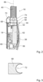
- Figure 2 shows, in particular, an interior of the ventilation housing 18.
- the ventilation housing 18 is made of plastic.
- the ventilation housing 18 has two interconnected housing shells, namely a first housing shell and a second housing shell. A curvature of the ventilation housing 18 is adapted to the curvature of a person's back.
- the ventilation housing 18 has a thickness d of less than 70 mm.
- the ventilation housing 18 has a thickness d of less than 50 mm.
- the ventilation housing 18 has a plurality of air inlet openings.
- the air inlet openings are formed by slots in one of the housing shells. During operation, the air inlet openings serve to draw in ambient air by means of an intake air flow, in particular through the fan 56.
- the fan 56 is arranged in the ventilation housing 18.
- the ventilation unit 14 is provided for generating an overpressure in the breathing mask unit 12.
- the fan 56 is provided for generating the overpressure in the breathing mask unit 12.
- the fan 56 is provided for generating a volume flow of the air flow 54 of at least 50 l/min and a maximum of 250 l/min.
- the fan 56 is provided for generating a volume flow of the air flow 54 of at least 80 l/min and a maximum of 120 l/min.
- the ventilation unit 14, by means of the fan 56 is provided for generating a relative overpressure compared to the surroundings in the breathing mask unit 12.
- the fan 56 is formed by an electric radial fan. In principle, however, another design that would appear expedient to a person skilled in the art would also be conceivable.
- the fan 56 is arranged on an outlet side of the ventilation housing 18. At the An air outlet opening 58 is arranged on the output side of the ventilation housing 18.
- the ventilation unit 14 further comprises a control and/or regulating unit 60, in particular a processor with a memory module, for controlling and/or regulating the fan 56 during operation.
- the control and/or regulating unit 60 is provided, in particular, for automatically adjusting a power level of the fan 56.
- the ventilation unit 14 has an energy storage device 62.
- the energy storage device 62 is formed by an accumulator.
- the energy storage device 62 serves to supply energy to the fan 56.
- the energy storage device 62 is arranged in the ventilation housing 18.
- the ventilation housing 18 accommodates the fan 56, partially the connecting unit 44, and the energy storage device 62.
- the ventilation housing 18 serves to protect and align the fan 56 and the energy storage device 62.
- the energy storage device 62 is designed to be replaceable.
- the ventilation unit 14 has a connection interface 64 for receiving the at least one connection unit 44.
- the connection interface 64 is formed integrally with the ventilation housing 18.
- the connection interface 64 is arranged at the air outlet opening 58. During operation, the air flow 54 is forwarded from the air outlet opening 58 to the breathing mask unit 12 (see FIG. Fig. 1 and Fig. 2 ).
- the connecting unit 44 connects the transfer unit 16 to the ventilation unit 14.
- the connecting unit 44 connects the transfer unit 16 to the ventilation unit 14 in an airtight manner with respect to the ambient air.
- the connecting unit 44 is largely formed by a cylindrical hose-housing adapter.
- the connecting unit 44 is intended to be arranged in the connection interface 64.
- the connection interface 64 has a cylindrical outer contour.
- the connecting unit 44 is partially arranged in the ventilation unit 14, in particular in the ventilation housing 18.
- the connecting unit 44 is partially arranged in the ventilation unit 14, in particular in the ventilation housing 18, through the connection interface 64.
- the connecting unit 44 is detachably connected to the ventilation unit 14.
- the ventilation unit 14 has a displaceable fixing element 68 (see Fig. 2 and Fig. 3 ).
- the at least one connecting unit 44 can be at least partially fixed in the ventilation unit 14 by means of the displaceable fixing element 68.
- the connecting unit 44 has a locking groove 70.
- the locking groove 70 is provided for at least partially receiving the at least one fixing element 68.
- the locking groove 70 extends completely around a circular circumference of the connecting unit 44.
- the connecting unit 44 is designed to be invariant with respect to rotation about an air flow axis 66.
- the connecting unit 44 can be inserted into the connection interface 64 in any rotation about the air flow axis 66.
- the fixing element 68 is in Figure 3 shown.
- the fixing element 68 is designed as a fixing plate.
- the fixing element 68 has a rounded fixing edge 72, which is intended to encompass the cylindrical connecting unit 44 along the locking groove 70.
- the fixing element 68 is intended to encompass at least 50%, in particular at least 60%, of a circumference of the connecting unit 44.
- the fixing element 68 limits the mobility of the connecting unit 44 in the connecting interface 64 along the air flow axis 66 to a maximum of 1 mm.
- the connecting interface 64 and the fixing element 68 limit the mobility of the connecting unit 44 in the connecting interface 64 perpendicular to the air flow axis 66 to a maximum of 0.5 mm.
- the fixing edge 72 is intended to bear against the connecting unit 44.
- a curvature of the fixing edge 72 corresponds to a circular curvature along the locking groove 70 around the cylindrical Connecting unit 44, in particular to enable rotation of the connecting unit 44 in the connecting interface 64.
- the connecting unit 44 is movably mounted on the ventilation unit 14.
- the connecting unit 44 is mounted on the ventilation unit 14 so as to be at least partially rotatable about an air flow axis 66 of the connecting unit 44.
- the connecting unit 44 is mounted on the ventilation unit 14 so as to be rotatable by 360° about the air flow axis 66 of the connecting unit 44. Rotation of the transfer unit 16 and the connecting unit 44 is limited by the flexibility of the transfer unit 16.
- the at least one connecting unit 44 has a valve element 74 for air flow regulation.
- the valve element 74 is designed as a return valve element.
- the at least one connecting unit 44 can be permanently connected to the at least one ventilation unit 14.
- the fixing element 68 can be welded to the ventilation housing 18 in a safety state.
- the connecting unit 44 is mounted on the ventilation unit 14 so as to be at least partially rotatable about the airflow axis 66 of the connecting unit 44.
- the respiratory protection system 50 has an external operating unit 20.
- the external operating unit 20 is formed by a remote control.
- the operating unit 20 has operating elements 22 and a control and/or regulating unit 24, which is provided for controlling and/or regulating the ventilation unit 14.
- the operating unit 20 has a battery element 26 for a power supply.
- the external operating unit 20 is connected to the ventilation unit 14, for example, by means of a cable 28.
- the control and/or regulating unit 24 of the external operating unit 20 is provided, in particular, to control the ventilation unit 14 depending on an input on the control elements 22.
- a power level of the fan 56 of the ventilation unit 14 can be set via the control elements 22.
- the fan 56 can be activated or deactivated via the control elements 22.
- the respiratory protection system 50 has a vest 46 for wear by a user 48.
- the vest 46 is formed from a fabric vest.
- the ventilation unit 14 is arranged on a back of the vest 46.
- the ventilation unit 14 is detachably connected to the vest 46.
- the ventilation unit 14 is worn on the back by a user 48 during operation using the vest 46.
- the external control unit 20 is intended to be worn by a user 48 on a chest.
- the external control unit 20 is arranged on a front of the vest 46.
Landscapes
- Engineering & Computer Science (AREA)
- Health & Medical Sciences (AREA)
- Mechanical Engineering (AREA)
- General Engineering & Computer Science (AREA)
- Pulmonology (AREA)
- General Health & Medical Sciences (AREA)
- Business, Economics & Management (AREA)
- Emergency Management (AREA)
- Respiratory Apparatuses And Protective Means (AREA)
Description
- Die Erfindung betrifft eine Gebläsevorrichtung für ein Atemschutzsystem, mit zumindest einer Ventilationseinheit, welche zu einer Luftzufuhr zu einer Atemmaskeneinheit vorgesehen ist, und mit einer Transfereinheit zu einem Lufttransfer von der Ventilationseinheit zu der Atemmaskeneinheit nach dem Oberbegriff des Anspruchs 1.
- Eine solche Atemmaskeneinheit ist beispielsweise aus der
WO 98/41306 A1 - Die Erfindung geht aus von einer Gebläsevorrichtung für ein Atemschutzsystem, mit zumindest einer Ventilationseinheit, welche zu einer Luftzufuhr zu einer Atemmaskeneinheit vorgesehen ist, und mit einer Transfereinheit zu einem Lufttransfer von der Ventilationseinheit zu der Atemmaskeneinheit.
- Es wird vorgeschlagen, dass die Gebläsevorrichtung eine zumindest teilweise beweglich an der Ventilationseinheit gelagerte Verbindungseinheit aufweist, welche die Transfereinheit mit der Ventilationseinheit, insbesondere zumindest im Wesentlichen luftdicht, verbindet und welche zumindest teilweise in der Ventilationseinheit angeordnet ist.
- Unter einer "Gebläsevorrichtung" soll in diesem Zusammenhang insbesondere eine Vorrichtung verstanden werden, die zu einer aktiven Erzeugung eines Luftstroms zu einer Atemluftversorgung eines Benutzers vorgesehen ist. Die Gebläsevorrichtung ist insbesondere von einer kompakten Gebläsevorrichtung gebildet. Die Gebläsevorrichtung ist insbesondere zu einem Tragen an dem Körper, wie beispielsweise auf dem Rücken und/oder an der Hüfte, vorgesehen. Die Gebläsevorrichtung ist in einem Betrieb insbesondere dazu vorgesehen, der Atemmaskeneinheit des Atemschutzsystems den Luftstrom zuzuführen. Vorzugsweise ist die Gebläsevorrichtung in einem Betrieb dazu vorgesehen, Luft aus einer Umgebung anzusaugen, die Luft zu reinigen, insbesondere zu filtern, und die gereinigte Luft einem Benutzer aktiv über die Transfereinheit, insbesondere über die Atemmaskeneinheit, zuzuführen. Vorzugsweise ist die Ventilationseinheit über die zumindest eine Transfereinheit mit der Atemmaskeneinheit des Atemschutzsystems verbunden. Vorzugsweise ist die Transfereinheit als eine Atemluftversorgungsleitung, wie beispielsweise ein Schlauch, bevorzugt ein Faltenbalgschlauch, ausgebildet. Bevorzugt ist die Ventilationseinheit zu einer Erzeugung eines aktiven Luftstroms vorgesehen. Die Ventilationseinheit ist insbesondere zu einer Erzeugung eines Überdruckluftstroms vorgesehen. Die Ventilationseinheit weist insbesondere einen Lüfter zu einer aktiven Erzeugung des Luftstroms auf. Der Lüfter ist in einem Betrieb insbesondere zu einer aktiven Erzeugung des Luftstroms vorgesehen. Der Lüfter ist insbesondere zu einem aktiven Ansaugen einer Luft aus einer Umgebung sowie zu einem aktiven Transport der Luft zu der Atemmaskeneinheit des Atemschutzsystems vorgesehen. Der Lüfter ist insbesondere von einem Axiallüfter und/oder Radiallüfter gebildet. Unter "vorgesehen" soll insbesondere speziell programmiert, ausgelegt und/oder ausgestattet verstanden werden. Darunter, dass ein Objekt zu einer bestimmten Funktion vorgesehen ist, soll insbesondere verstanden werden, dass das Objekt diese bestimmte Funktion in zumindest einem Anwendungs- und/oder Betriebszustand erfüllt und/oder ausführt.
- Die Ventilationseinheit weist ein Ventilationsgehäuse auf.
- Vorzugsweise ist die Verbindungseinheit als eine Adaptereinheit zu einer Verbindung der Transfereinheit mit dem Ventilationsgehäuse ausgebildet. Vorzugsweise ist die Verbindungseinheit als ein Schlauch-Gehäuse-Adapter ausgebildet. Vorzugsweise ist die Verbindungseinheit fest, insbesondere unbeweglich, bevorzugt untrennbar, mit der Transfereinheit verbunden. Die Verbindungseinheit kann einstückig mit der Transfereinheit ausgebildet sein. Vorzugsweise verbindet die Verbindungseinheit die als Atemluftversorgungsleitung ausgebildete Transfereinheit, bevorzugt zumindest im Wesentlichen luftdicht, mit dem Ventilationsgehäuse. Darunter, dass "die Verbindungseinheit die Transfereinheit mit der Ventilationseinheit zumindest im Wesentlichen luftdicht verbindet" soll insbesondere verstanden werden, dass der Luftstrom zwischen der Ventilationseinheit und der Transfereinheit durch die Verbindung ermöglicht ist, wobei die Verbindungseinheit einen Luftaustausch zwischen einer außerhalb der Transfereinheit und außerhalb der Ventilationseinheit angeordneten Umgebungsluft und dem Luftstrom unterbindet. Insbesondere definiert der Luftstrom eine definierte Luftstromachse, welche insbesondere durch eine Ausrichtung des Lüfters definiert ist. Vorzugsweise ist die Luftstromachse von dem Lüfter zu der Transfereinheit, insbesondere zu der Verbindungseinheit, ausgerichtet. Vorzugsweise ist eine Längsachse der Verbindungseinheit zumindest im Wesentlichen parallel zu der Luftstromachse ausgerichtet. Unter einer "Längsachse eines Objekts oder einer Einheit" soll vorzugsweise eine Achse verstanden werden, welche parallel zu einer längsten Außenkante eines kleinsten gedachten Quaders verläuft, welcher das Objekt oder die Einheit gerade noch vollständig umschließt. Unter zumindest "im Wesentlichen parallel" soll hier insbesondere eine Ausrichtung einer Richtung relativ zu einer Bezugsrichtung, insbesondere in einer Ebene, verstanden werden, wobei die Richtung gegenüber der Bezugsrichtung eine Abweichung insbesondere kleiner als 8°, vorteilhaft kleiner als 5° und besonders vorteilhaft kleiner als 2° aufweist. Unter zumindest "im Wesentlichen senkrecht" soll insbesondere eine Ausrichtung einer Richtung relativ zu einer Bezugsrichtung verstanden werden, wobei die Richtung und die Bezugsrichtung, insbesondere in einer Ebene betrachtet, einen Winkel von 90° einschließen und der Winkel eine maximale Abweichung von insbesondere kleiner als 8°, vorteilhaft kleiner als 5° und besonders vorteilhaft kleiner als 2° aufweist.
- Die Verbindungseinheit ist zumindest teilweise beweglich an dem Ventilationsgehäuse gelagert. Darunter, dass "die Verbindungseinheit zumindest teilweise beweglich an der Ventilationseinheit, insbesondere an dem Ventilationsgehäuse," gelagert ist soll insbesondere verstanden werden, dass die Verbindungseinheit um die Luftstromachse drehbar an der Ventilationseinheit, insbesondere an dem Ventilationsgehäuse gelagert ist, wobei die Verbindungseinheit insbesondere zumindest im Wesentlichen parallel der Luftstromrichtung bis auf eine Abweichung von maximal 2 mm, bevorzugt maximal 1 mm, unbeweglich gelagert ist und wobei die Verbindungseinheit insbesondere zumindest im Wesentlichen senkrecht zu der Luftstromrichtung bis auf eine Abweichung von maximal 2 mm, bevorzugt maximal 1 mm, unbeweglich gelagert ist.
- Darunter, dass "die Verbindungseinheit zumindest teilweise in der Ventilationseinheit angeordnet ist" soll insbesondere verstanden werden, dass die Verbindungseinheit zumindest teilweise in dem Ventilationsgehäuse angeordnet ist. Erfindungsgemäß weist das Ventilationsgehäuse eine Verbindungsschnittstelle auf, durch welche die zumindest eine Verbindungseinheit zumindest teilweise in dem Ventilationsgehäuse angeordnet werden kann.
- Durch die erfindungsgemäße Ausgestaltung der Gebläsevorrichtung kann eine vorteilhaft bewegliche Verbindung der Transfereinheit mit der Ventilationseinheit erreicht werden. Es kann insbesondere eine vorteilhaft robuste Verbindung der Transfereinheit mit der Ventilationseinheit bereitgestellt werden. Es kann insbesondere eine vorteilhaft kompakte Verbindung der Transfereinheit mit der Ventilationseinheit bereitgestellt werden.
- Des Weiteren wird vorgeschlagen, dass die Verbindungseinheit trennbar mit der Ventilationseinheit verbunden ist. Vorzugsweise ist die Verbindungseinheit trennbar mit dem Ventilationsgehäuse verbunden. Bevorzugt ist die Verbindungseinheit zu einem zumindest teilweisen Einstecken in das Verbindungsgehäuse vorgesehen. Bevorzugt ist die Verbindungseinheit in dem Ventilationsgehäuse trennbar mit der Ventilationseinheit verbunden. Es kann eine vorteilhafte Lösbarkeit der Verbindung der Transfereinheit mit der Ventilationseinheit, insbesondere dem Ventilationsgehäuse, erreicht werden.
- Ferner wird vorgeschlagen, dass die Verbindungseinheit zumindest teilweise um eine, insbesondere die bereits genannte, Luftstromachse der Verbindungseinheit drehbar an der Ventilationseinheit, insbesondere an dem Ventilationsgehäuse, gelagert ist. Vorzugsweise ist eine Verdrehung der Verbindungseinheit um die Luftstromachse der Verbindungseinheit durch eine Elastizität der Transfereinheit begrenzt. Die Verdrehung der Verbindungseinheit um die Luftstromachse der Verbindungseinheit kann alternativ oder zusätzlich durch die Ventilationseinheit, insbesondere die Fixierplatte und/oder das Ventilationsgehäuse, und/oder die Verbindungseinheit begrenzt sein. Vorzugsweise ist eine Verdrehung der Verbindungseinheit um die Luftstromachse der Verbindungseinheit auf einen Drehwinkel von maximal 270°, bevorzugt von maximal 180°, besonders bevorzugt von maximal 120° und ganz besonders bevorzugt von maximal 90°, begrenzt. Es kann eine vorteilhaft einer Nutzerbewegung folgende Verbindung der Transfereinheit mit der Ventilationseinheit erreicht werden. Insbesondere kann eine vorteilhaft unanfällige Verbindungseinheit, insbesondere Transfereinheit, erreicht werden. Insbesondere kann eine vorteilhaft langlebige, insbesondere robuste, Verbindung der Transfereinheit mit der Ventilationseinheit erreicht werden.
- Des Weiteren wird vorgeschlagen, dass die zumindest eine Verbindungseinheit mit der zumindest einen Ventilationseinheit unlösbar verbunden ist. Die Verbindungseinheit kann unlösbar mit dem Ventilationsgehäuse verbunden sein. Insbesondere kann die Verbindungseinheit, bevorzugt um die Luftstromachse, drehbar und unlösbar mit dem Ventilationsgehäuse verbunden sein. Insbesondere kann ein Fixierelement der Ventilationseinheit zu einem Fixieren der Verbindungseinheit an der Ventilationseinheit unlösbar mit dem Ventilationsgehäuse verbunden sein. Es kann eine vorteilhaft robuste Verbindung der Verbindungseinheit mit der Ventilationseinheit, bevorzugt in dem Ventilationsgehäuse, erreicht werden.
- Ferner wird vorgeschlagen, dass die Ventilationseinheit ein verschiebbares Fixierelement aufweist, durch welches die zumindest eine Verbindungseinheit zumindest teilweise in der Ventilationseinheit fixierbar ist. Erfindungsgemäß umfasst die Ventilationseinheit ein Fixierelement, bevorzugt eine Fixierplatte, welche insbesondere dazu vorgesehen ist, die Verbindungseinheit an dem Ventilationsgehäuse zu fixieren. Erfindungsgemäß vorzugsweise ist das Fixierelement, bevorzugt die Fixierplatte, zu einem Verschieben in dem Ventilationsgehäuse vorgesehen. Vorzugsweise ist das Fixierelement, bevorzugt die Fixierplatte, zu einem teilweisen Umgreifen der Verbindungseinheit vorgesehen. Vorzugsweise ist das Fixierelement, bevorzugt die Fixierplatte, dazu vorgesehen, die Verbindungseinheit, insbesondere durch ein Verschieben der Fixierplatte, trennbar mit dem Ventilationsgehäuse zu verbinden. Insbesondere kann die Verbindungseinheit durch das Fixierelement, bevorzugt die Fixierplatte, bevorzugt ein Verschieben der Fixierplatte, mit dem Ventilationsgehäuse verbunden werden. Das Fixierelement, bevorzugt die Fixierplatte, kann als Rastplatte ausgebildet sein, insbesondere zu einer Rastverbindung mit der Verbindungseinheit. Vorzugsweise blockiert das Fixierelement, bevorzugt die Fixierplatte, bei einem teilweisen Umgreifen der Verbindungseinheit eine Bewegung der Verbindungseinheit zumindest im Wesentlichen parallel zu der Luftstromachse, insbesondere zumindest bis auf eine Abweichung von maximal 2 mm, bevorzugt maximal 1 mm. Bevorzugt ist die Verbindungseinheit zu einem zumindest teilweisen Einstecken in das Verbindungsgehäuse vorgesehen. Es kann eine vorteilhaft unkomplizierte und stabile Verbindung der Verbindungseinheit mit dem Verbindungsgehäuse erreicht werden. Insbesondere kann ein vorteilhaft unkompliziertes Lösen und/oder Herstellen der Verbindung der Verbindungseinheit mit dem Verbindungsgehäuse erreicht werden.
- Des Weiteren wird vorgeschlagen, dass die Verbindungseinheit eine Rastnut zu einer zumindest teilweisen Aufnahme des zumindest einen Fixierelements aufweist. Vorzugsweise ist die zumindest eine Rastnut an einer Außenseite der Verbindungseinheit angeordnet. Vorzugsweise ist die zumindest eine Rastnut an einer der Ventilationseinheit zugewandten Seite, insbesondere entlang der Luftstromachse, der Verbindungseinheit angeordnet. Vorzugsweise erstreckt sich die zumindest eine Rastnut in einer Ebene senkrecht zur Luftstromachse um den gesamten Umfang der Verbindungseinheit. Insbesondere ist die Rastnut dazu vorgesehen, das zumindest eine Fixierelement zumindest teilweise, bevorzugt eine abgerundete Außenkante des zumindest einen Fixierelements, insbesondere zumindest im Wesentlichen vollständig, aufzunehmen. Es kann ein vorteilhaftes Ineinandergreifen der Verbindungseinheit und der Ventilationseinheit zu einem vorteilhaft sicheren Fixieren der Verbindungseinheit an der Ventilationseinheit erreicht werden.
- Ferner wird vorgeschlagen, dass die zumindest eine Verbindungseinheit zumindest ein Ventilelement zu einer Luftstromregulation aufweist. Vorzugsweise ist das zumindest eine Ventilelement in einem Inneren der Verbindungseinheit angeordnet. Vorzugsweise ist das zumindest eine Ventilelement lösbar, insbesondere austauschbar, in dem Inneren der Verbindungseinheit angeordnet. Das Ventilelement kann ein Filterelement umfassen. Das Ventilelement ist vorzugsweise als ein Rücklaufventilelement ausgebildet. Das Ventilelement kann insbesondere dazu vorgesehen sein, den Luftstrom zu der Atemmaskeneinheit in einen Teilluftkanal der Transfereinheit zu leiten. Beispielsweise kann die Transfereinheit zwei Teilkanäle aufweisen, jeweils einen zu einem Hintransport von Luft zu der Atemmaskeneinheit und einen zu einem Abtransport von Luft von der Atemmaskeneinheit zu einem Luftausgang, welcher insbesondere an einem der Ventilationseinheit zugewandten Ende der Transfereinheit angeordnet ist. Es kann ein vorteilhaft gerichteter Luftstrom erreicht werden. Insbesondere kann ein Risiko eines Rücklaufs von sauerstoffarmer Luft zu der Ventilationseinheit vorteilhaft verringert werden. Es kann ein vorteilhafter Sicherheitsstandard erreicht werden.
- Des Weiteren wird vorgeschlagen, dass die Ventilationseinheit ein Ventilationsgehäuse und eine Verbindungsschnittstelle zu einer Aufnahme der zumindest einen Verbindungseinheit aufweist, und die Verbindungsschnittstelle einstückig mit dem Ventilationsgehäuse ausgebildet ist. Unter "einstückig" soll insbesondere zumindest stoff-schlüssig verbunden verstanden werden, beispielsweise durch einen Schweißprozess, einen Klebeprozess, einen Anspritzprozess und/oder einen anderen, dem Fachmann als sinnvoll erscheinenden Prozess, und/oder vorteilhaft in einem Stück geformt verstanden werden, wie beispielsweise durch eine Herstellung aus einem Guss und/oder durch eine Herstellung in einem Ein- oder Mehrkomponentenspritzverfahren und vorteilhaft aus einem einzelnen Rohling. Es kann eine vorteilhaft stabile Verbindungseinheit erreicht werden. Darüber hinaus wird eine Transfereinheit vorgeschlagen mit einer Verbindungseinheit, wobei die Verbindungseinheit und die Transfereinheit einstückig ausgebildet sind. Bevorzugt ist die Transfereinheit als ein flexibler Luftschlauch, insbesondere als ein Faltenbalgluftschlauch, ausgebildet. Besonders bevorzugt ist die Transfereinheit zumindest teilweise aus einem künstlichen oder natürlichen Elastomer ausgebildet. Insbesondere ist eine Luftleitlänge der Transfereinheit, insbesondere um zumindest 10% einer Luftleitlänge in einem kraftwirkungsfreien Zustand der Transfereinheit, variabel ausgebildet. Es kann eine vorteilhafte Kombinierbarkeit der Transfereinheit mit der Ventilationseinheit und/oder der Atemmaskeneinheit erreicht werden.
- Darüber hinaus wird ein Atemschutzsystem vorgeschlagen mit zumindest einer, insbesondere der bereits genannten, Atemmaskeneinheit und mit einer Gebläsevorrichtung nach einem der vorhergehenden Ansprüche. Vorzugsweise ist die Atemmaskeneinheit zu einem Luftleiten mit der Transfereinheit lösbar oder unlösbar verbunden. Das Atemschutzsystem kann eine Bedieneinheit umfassen. Das Atemschutzsystem kann eine Weste umfassen. Es kann eine vorteilhafte Kombinierfähigkeit der Transfereinheit mit der Atemmaskeneinheit erreicht werden.
- Die erfindungsgemäße Gebläsevorrichtung, die erfindungsgemäße Transfereinheit und/oder das erfindungsgemäße Atemschutzsystem sollen/soll hierbei nicht auf die oben beschriebene Anwendung und Ausführungsform beschränkt sein. Insbesondere können/kann die erfindungsgemäße Gebläsevorrichtung, die erfindungsgemäße Transfereinheit und/oder das erfindungsgemäße Atemschutzsystem zu einer Erfüllung einer hierin beschriebenen Funktionsweise eine von einer hierin genannten Anzahl von einzelnen Elementen, Bauteilen und Einheiten abweichende Anzahl aufweisen.
- Weitere Vorteile ergeben sich aus der folgenden Zeichnungsbeschreibung. In den Zeichnungen ist ein Ausführungsbeispiel der Erfindung dargestellt. Die Zeichnungen, die Beschreibung und die Ansprüche enthalten zahlreiche Merkmale in Kombination. Der Fachmann wird die Merkmale zweckmäßigerweise auch einzeln betrachten und zu sinnvollen weiteren Kombinationen zusammenfassen.
- Es zeigen:
- Fig. 1
- ein Atemschutzsystem mit einer erfindungsgemäßen Gebläsevorrichtung, mit einer Atemmaskeneinheit, mit einer Weste und mit einer externen Bedieneinheit und einen Benutzer in einer schematischen Darstellung,
- Fig. 2
- die erfindungsgemäße Gebläsevorrichtung des Atemschutzsystems in einer schematischen Schnittdarstellung entlang der Schnittlinie II-II und
- Fig. 3
- ein Fixierelement einer Ventilationseinheit der erfindungsgemäßen Gebläsevorrichtung in einer schematischen Darstellung.
- Die
Figur 1 zeigt ein Atemschutzsystem 50. Das Atemschutzsystem 50 ist von einem Gebläse-Atemschutzsystem gebildet. Das Atemschutzsystem 50 ist insbesondere von einem Gebläse-Atemschutzsystem der Sicherheitsklasse TH3 gebildet. Das Atemschutzsystem 50 ist zu einem Schutz eines Benutzers 48 vor Partikeln wie Rauch, Aerosolen und/oder Staub vorgesehen. Ferner kann das Atemschutzsystem 50 zusätzlich vor unangenehmen Gerüchen und schädlichem Ozon schützen. Insbesondere ist denkbar, dass das Atemschutzsystem 50 in Umgebungen mit gesundheitsschädlichen oder gar toxischen Gasen den Benutzer 48 vor organischen, anorganischen und/oder sauren Gasen schützt. Das Atemschutzsystem 50 umfasst eine Gebläsevorrichtung 10. Die Gebläsevorrichtung 10 ist für das Atemschutzsystem 50 vorgesehen. Das Atemschutzsystem 50 weist eine Atemmaskeneinheit 12 auf. Die Gebläsevorrichtung 10 weist eine Ventilationseinheit 14 auf. Die Gebläsevorrichtung 10 weist eine Transfereinheit 16 auf. Die Gebläsevorrichtung 10 weist eine Verbindungseinheit 44 auf. Die Verbindungseinheit 44 ist zu einer Verbindung der Transfereinheit 16 mit der Ventilationseinheit 14 vorgesehen. - Die Ventilationseinheit 14 ist zu einer Erzeugung eines Luftstroms 54 vorgesehen. Die Ventilationseinheit 14 ist zu der Erzeugung des Luftstroms 54 für die Atemmaskeneinheit 12 vorgesehen. Die Ventilationseinheit 14 weist einen Lüfter 56 zu der Erzeugung des Luftstroms 54 auf. Die Ventilationseinheit 14 ist zu einer Luftzufuhr zu der Atemmaskeneinheit 12 vorgesehen.
- Die Transfereinheit 16 ist teilweise als flexibler Luftschlauch ausgebildet. Die Transfereinheit 16 ist zu einem Lufttransfer von der Ventilationseinheit 14 zu der Atemmaskeneinheit 12 vorgesehen. Die Transfereinheit 16 umfasst einen Y-Maskenkoppelluftschlauch 38. Die Transfereinheit 16 umfasst einen Ventilationskoppelluftschlauch 40. Der Y-Maskenkoppelluftschlauch 38 ist weniger flexibel als der Ventilationskoppelluftschlauch 40 ausgebildet. Der Ventilationskoppelluftschlauch 40 ist als Faltenbalgschlauch ausgebildet.
- Die Atemmaskeneinheit 12 weist einen Maskengrundkörper 30 auf. Der Maskengrundkörper 30 ist dazu vorgesehen, eine Mund- und Nasenpartie des Benutzers 48 zu verdecken. Ferner ist der Maskengrundkörper 30 dazu vorgesehen, zumindest teilweise einen Atembereich 32 zu begrenzen.
- Die Atemmaskeneinheit 12 weist ferner zwei Befestigungsbänder 34, 34' zu einer Fixierung des Maskengrundkörpers 30 an einem Kopf 52 des Benutzers 48 auf. Die Befestigungsbänder 34, 34' sind von einem elastischen Band, wie insbesondere einem Gummiband, gebildet. Das Befestigungsband 34 ist in einem getragenen Zustand der Atemmaskeneinheit 12 dazu vorgesehen, um einen Scheitel, insbesondere über den Kopf 52, geführt zu werden. Das Befestigungsband 34' ist in einem getragenen Zustand der Atemmaskeneinheit 12 dazu vorgesehen, um einen Hinterkopf, insbesondere in einem Nackenbereich, geführt zu werden.
- Ferner ist die Atemmaskeneinheit 12, insbesondere der Maskengrundkörper 30, mit der Transfereinheit 16 verbunden. Die Atemmaskeneinheit 12, insbesondere der Maskengrundkörper 30, ist über zwei Rastschnallen 36 mit der Transfereinheit 16 verbunden. Der Maskengrundkörper 30 ist über die Rastschnallen 36 mit dem Y-Maskenkoppelluftschlauch 38 luftleitend verbunden. Die Verbindung des Maskengrundkörpers 30 mit dem Y-Maskenkoppelluftschlauch 38 ist luftdicht gegenüber einer Umgebungsluft. Der Y-Maskenkoppelluftschlauch 38 ist zu einer Stabilisierung in dem Nackenbereich mit dem Befestigungsband 34' verbunden.
- Der Y-Maskenkoppelluftschlauch 38 ist mit dem Ventilationskoppelluftschlauch 40 unlösbar verbunden. Insbesondere weist der Y-Maskenkoppelluftschlauch 38 ein Y-Endstück 42 auf. Alternativ könnte der Y-Maskenkoppelluftschlauch 38 auch ein T-Endstück anstelle des Y-Endstücks 42 aufweisen.
- Der Ventilationskoppelluftschlauch 40 verbindet die Transfereinheit 16 luftleitend mit der Verbindungseinheit 44. Die Verbindungseinheit 44 verbindet die Transfereinheit 16 luftleitend mit der Ventilationseinheit 14. Die Verbindungseinheit 44 verbindet den Ventilationskoppelluftschlauch 40 luftleitend mit der Ventilationseinheit 14. Der Luftstrom 54 ist von der Ventilationseinheit 14 durch die Verbindungseinheit 44 und durch die Transfereinheit 16 zu der Atemmaskeneinheit 12 geführt. Die Verbindungseinheit 44 und die Transfereinheit 16 sind einstückig ausgebildet. Der Ventilationskoppelluftschlauch 40 ist einstückig mit der Verbindungseinheit 44 ausgebildet.
- Die Ventilationseinheit 14 weist ein Ventilationsgehäuse 18 auf.
Figur 2 zeigt insbesondere einen Innenraum des Ventilationsgehäuses 18. Das Ventilationsgehäuse 18 ist aus Kunststoff ausgebildet. Das Ventilationsgehäuse 18 weist zwei miteinander verbundene Gehäuseschalen auf, und zwar eine erste Gehäuseschale und eine zweite Gehäuseschale. Eine Krümmung des Ventilationsgehäuses 18 ist an eine Rückenkrümmung eines Menschen angepasst. Das Ventilationsgehäuse 18 weist eine Dicke d von weniger als 70 mm auf. Das Ventilationsgehäuse 18 weist eine Dicke d von weniger als 50 mm auf. Ferner weist das Ventilationsgehäuses 18 mehrere Lufteinlassöffnungen auf. Die Lufteinlassöffnungen sind von Schlitzen in einer der Gehäuseschalen gebildet. Die Lufteinlassöffnungen dienen in einem Betrieb zu einem Ansaugen einer Umgebungsluft mittels eines Ansaugluftstroms, insbesondere durch den Lüfter 56. - In dem Ventilationsgehäuse 18 ist der Lüfter 56 angeordnet. Die Ventilationseinheit 14 ist zu einer Erzeugung eines Überdrucks in der Atemmaskeneinheit 12 vorgesehen. Der Lüfter 56 ist zu einer Erzeugung des Überdrucks in der Atemmaskeneinheit 12 vorgesehen. Der Lüfter 56 ist zu einer Erzeugung eines Volumenstroms des Luftstroms 54 von zumindest 50 I/min und maximal 250l/min vorgesehen. Der Lüfter 56 ist zu einer Erzeugung eines Volumenstroms des Luftstroms 54 von zumindest 80 I/min und maximal 120l/min vorgesehen. In einem Betrieb ist die Ventilationseinheit 14 mittels des Lüfters 56 zu einer Erzeugung eines relativen Überdrucks gegenüber einer Umgebung in der Atemmaskeneinheit 12 vorgesehen. Der Lüfter 56 ist von einem elektrischen Radiallüfter gebildet. Grundsätzlich wäre jedoch auch eine andere, einem Fachmann als sinnvoll erscheinende Ausgestaltung denkbar. Der Lüfter 56 ist an einer Ausgangsseite des Ventilationsgehäuses 18 angeordnet. An der Ausgangsseite des Ventilationsgehäuses 18 ist eine Luftauslassöffnung 58 angeordnet.
- Die Ventilationseinheit 14 weist ferner eine Steuer- und/oder Regeleinheit 60, insbesondere einen Prozessor mit Speichermodul, zu einer Steuerung und/oder Regelung des Lüfters 56 in einem Betrieb auf. Die Steuer- und/oder Regeleinheit 60 ist insbesondere zu einer automatischen Anpassung einer Leistungsstufe des Lüfters 56 vorgesehen.
- Des Weiteren weist die Ventilationseinheit 14 einen Energiespeicher 62 auf. Der Energiespeicher 62 ist von einem Akkumulator gebildet. Der Energiespeicher 62 dient zu einer Energieversorgung des Lüfters 56. Der Energiespeicher 62 ist in dem Ventilationsgehäuse 18 angeordnet. Das Ventilationsgehäuse 18 nimmt den Lüfter 56, teilweise die Verbindungseinheit 44 und den Energiespeicher 62, auf. Das Ventilationsgehäuse 18 dient zu einem Schutz und einer Ausrichtung des Lüfters 56 und des Energiespeichers 62. Ferner ist der Energiespeicher 62 auswechselbar ausgebildet.
- Die Ventilationseinheit 14 weist eine Verbindungsschnittstelle 64 zu einer Aufnahme der zumindest einen Verbindungseinheit 44 auf. Die Verbindungsschnittstelle 64 ist einstückig mit dem Ventilationsgehäuse 18 ausgebildet. Die Verbindungsschnittstelle 64 ist an der Luftauslassöffnung 58 angeordnet. Der Luftstrom 54 wird in einem Betrieb von der Luftauslassöffnung 58 an die Atemmaskeneinheit 12 weitergeleitet (vgl.
Fig. 1 undFig. 2 ). - Die Verbindungseinheit 44 verbindet die Transfereinheit 16 mit der Ventilationseinheit 14. Die Verbindungseinheit 44 verbindet die Transfereinheit 16 mit der Ventilationseinheit 14 luftdicht in Bezug auf die Umgebungsluft.
- Die Verbindungseinheit 44 ist zum Großteil von einem zylinderförmigen Schlauch-Gehäuse-Adapter gebildet. Die Verbindungseinheit 44 ist dazu vorgesehen, in der Verbindungsschnittstelle 64 angeordnet zu werden. Die Verbindungsschnittstelle 64 weist eine zylinderförmige Außenkontur auf. Die Verbindungseinheit 44 ist teilweise in der Ventilationseinheit 14, insbesondere in dem Ventilationsgehäuse 18, angeordnet. Die Verbindungseinheit 44 ist durch die Verbindungsschnittstelle 64 teilweise in der Ventilationseinheit 14, insbesondere in dem Ventilationsgehäuse 18, angeordnet.
- Die Verbindungseinheit 44 ist trennbar mit der Ventilationseinheit 14 verbunden. Die Ventilationseinheit 14 weist ein verschiebbares Fixierelement 68 auf (vgl.
Fig. 2 und Fig. 3 ). Durch das verschiebbare Fixierelement 68 ist die zumindest eine Verbindungseinheit 44 zumindest teilweise in der Ventilationseinheit 14 fixierbar. Die Verbindungseinheit 44 weist eine Rastnut 70 auf. Die Rastnut 70 ist zu einer zumindest teilweisen Aufnahme des zumindest einen Fixierelements 68 vorgesehen. Die Rastnut 70 erstreckt sich vollständig um einen kreisförmigen Umfang der Verbindungseinheit 44. Die Verbindungseinheit 44 ist in Bezug auf eine Verdrehung um eine Luftstromachse 66 invariant ausgebildet. Die Verbindungseinheit 44 kann in jeglicher Verdrehung um die Luftstromachse 66 in die Verbindungsschnittstelle 64 eingesteckt werden. - Das Fixierelement 68 ist in
Figur 3 gezeigt. Das Fixierelement 68 ist als eine Fixierplatte ausgebildet. Das Fixierelement 68 weist eine abgerundete Fixierkante 72 auf, welche dazu vorgesehen ist, die zylinderförmige Verbindungseinheit 44 entlang der Rastnut 70 zu umgreifen. Das Fixierelement 68 ist zu einem Umgreifen von zumindest 50%, insbesondere von zumindest 60%, eines Umfangs der Verbindungseinheit 44 vorgesehen. Das Fixierelement 68 begrenzt eine Beweglichkeit der Verbindungseinheit 44 in der Verbindungsschnittstelle 64 entlang der Luftstromachse 66 auf maximal 1 mm. Die Verbindungsschnittstelle 64 und das Fixierelement 68 begrenzen eine Beweglichkeit der Verbindungseinheit 44 in der Verbindungsschnittstelle 64 senkrecht zu der Luftstromachse 66 auf maximal 0,5 mm. Die Fixierkante 72 ist dazu vorgesehen, an der Verbindungseinheit 44 anzuliegen. Eine Krümmung der Fixierkante 72 entspricht einer kreisförmigen Krümmung entlang der Rastnut 70 um die zylinderförmige Verbindungseinheit 44, insbesondere um ein Verdrehen der Verbindungseinheit 44 in der Verbindungsschnittstelle 64 zu ermöglichen. - Die Verbindungseinheit 44 ist beweglich an der Ventilationseinheit 14 gelagert. Die Verbindungseinheit 44 ist zumindest teilweise um eine Luftstromachse 66 der Verbindungseinheit 44 drehbar an der Ventilationseinheit 14 gelagert. Die Verbindungseinheit 44 ist um 360° um die Luftstromachse 66 der Verbindungseinheit 44 drehbar an der Ventilationseinheit 14 gelagert. Eine Verdrehung der Transfereinheit 16 und der Verbindungseinheit 44 ist durch eine Flexibilität der Transfereinheit 16 begrenzt.
- Die zumindest eine Verbindungseinheit 44 weist ein Ventilelement 74 zu einer Luftstromregulation auf. Insbesondere ist das Ventilelement 74 als ein Rücklaufventilelement ausgebildet.
- Die zumindest eine Verbindungseinheit 44 kann mit der zumindest einen Ventilationseinheit 14 unlösbar verbunden sein. Beispielsweise kann das Fixierelement 68 mit dem Ventilationsgehäuse 18 in einem Sicherheitszustand verschweißt sein. In dem Sicherheitszustand ist die Verbindungseinheit 44 zumindest teilweise um die Luftstromachse 66 der Verbindungseinheit 44 drehbar an der Ventilationseinheit 14 gelagert.
- Ferner weist das Atemschutzsystem 50 eine externe Bedieneinheit 20 auf. Die externe Bedieneinheit 20 ist von einer Fernbedienung gebildet. Die Bedieneinheit 20 weist Bedienelemente 22 und eine Steuer- und/oder Regeleinheit 24 auf, welche zu einer Steuerung und/oder Regelung der Ventilationseinheit 14 vorgesehen ist. Die Bedieneinheit 20 weist ein Akkuelement 26 zu einer Energieversorgung auf. Die externe Bedieneinheit 20 ist beispielhaft mittels eines Kabels 28 mit der Ventilationseinheit 14 verbunden. Die Steuer- und/oder Regeleinheit 24 der externen Bedieneinheit 20 ist insbesondere dazu vorgesehen, die Ventilationseinheit 14 abhängig von einer Eingabe an den Bedienelementen 22 anzusteuern. Über die Bedienelemente 22 lässt sich beispielsweise eine Leistungsstufe des Lüfters 56 der Ventilationseinheit 14 einstellen. Ferner lässt sich über die Bedienelemente 22 der Lüfter 56 aktivieren oder deaktivieren.
- Des Weiteren weist das Atemschutzsystem 50 eine Weste 46 zu einem Tragen durch einen Benutzer 48 auf. Die Weste 46 ist von einer Stoffweste gebildet. Auf einer Rückseite der Weste 46 ist die Ventilationseinheit 14 angeordnet. Die Ventilationseinheit 14 ist lösbar mit der Weste 46 verbunden. Die Ventilationseinheit 14 wird von einem Benutzer 48 in einem Betrieb mittels der Weste 46 auf dem Rücken getragen. Ferner ist die externe Bedieneinheit 20 dazu vorgesehen, von einem Benutzer 48 an einer Brust getragen zu werden. Die externe Bedieneinheit 20 ist auf einer Vorderseite der Weste 46 angeordnet.
-
- 10
- Gebläsevorrichtung
- 12
- Atemmaskeneinheit
- 14
- Ventilationseinheit
- 16
- Transfereinheit
- 18
- Ventilationsgehäuse
- 20
- Bedieneinheit
- 22
- Bedienelement
- 24
- Steuer- und/oder Regeleinheit
- 26
- Akkuelement
- 28
- Kabel
- 30
- Maskengrundkörper
- 32
- Atembereich
- 34
- Befestigungsband
- 36
- Rastschnalle
- 38
- Y-Maskenkoppelluftschlauch
- 40
- Ventilationskoppelluftschlauch
- 42
- Y-Endstück
- 44
- Verbindungseinheit
- 46
- Weste
- 48
- Benutzer
- 50
- Atemschutzsystem
- 52
- Kopf
- 54
- Luftstrom
- 56
- Lüfter
- 58
- Luftauslassöffnung
- 60
- Steuer- und/oder Regeleinheit
- 62
- Energiespeicher
- 64
- Verbindungsschnittstelle
- 66
- Luftstromachse
- 68
- Fixierelement
- 70
- Rastnut
- 72
- Fixierkante
- 74
- Ventilelement
- d
- Dicke
Claims (8)
- Gebläsevorrichtung für ein Atemschutzsystem (50), mit zumindest einer Ventilationseinheit (14), welche zu einer Luftzufuhr zu einer Atemmaskeneinheit (12) vorgesehen ist, mit einer Transfereinheit (16) zu einem Lufttransfer von der Ventilationseinheit (14) zu der Atemmaskeneinheit (12), und mit einer zumindest teilweise beweglich an der Ventilationseinheit (14) gelagerten Verbindungseinheit (44), welche die Transfereinheit (16) mit der Ventilationseinheit (14), insbesondere zumindest im Wesentlichen luftdicht, verbindet und welche zumindest teilweise in der Ventilationseinheit (14) angeordnet, wobeidie Ventilationseinheit (14) ein Ventilationsgehäuse (18) und eine Verbindungsschnittstelle (64) zu einer Aufnahme der zumindest einen Verbindungseinheit (44) aufweist, wobei die Verbindungsschnittstelle (64) einstückig mit dem Ventilationsgehäuse (18) ausgebildet ist,dadurch gekennzeichnet, dassdie Ventilationseinheit (14) ein verschiebbares Fixierelement (68) aufweist, durch welches die zumindest eine Verbindungseinheit (44) zumindest teilweise in der Ventilationseinheit (14) fixierbar ist, wobei das Fixierelement (68) dazu vorgesehen ist, die Verbindungseinheit (44) an dem Ventilationsgehäuse (18) zu fixieren und wobei das Fixierelement (68) zu einem Verschieben in dem Ventilationsgehäuse (18) vorgesehen ist.
- Gebläsevorrichtung nach Anspruch 1, dadurch gekennzeichnet, dass die Verbindungseinheit (44) trennbar mit der Ventilationseinheit (14) verbunden ist.
- Gebläsevorrichtung nach Anspruch 1 oder 2, dadurch gekennzeichnet, dass die Verbindungseinheit (44) zumindest teilweise um eine Luftstromachse (66) der Verbindungseinheit (44) drehbar an der Ventilationseinheit (14) gelagert ist.
- Gebläsevorrichtung nach einem der vorhergehenden Ansprüche, dadurch gekennzeichnet, dass die zumindest eine Verbindungseinheit (44) mit der zumindest einen Ventilationseinheit (14) unlösbar verbunden ist.
- Gebläsevorrichtung nach einem der vorhergehenden Ansprüche, dadurch gekennzeichnet, dass die Verbindungseinheit (44) eine Rastnut (70) aufweist, zu einer zumindest teilweisen Aufnahme des zumindest einen Fixierelements (68).
- Gebläsevorrichtung nach einem der vorhergehenden Ansprüche, dadurch gekennzeichnet, dass die zumindest eine Verbindungseinheit (44) zumindest ein Ventilelement (74) zu einer Luftstromregulation aufweist.
- Transfereinheit mit einer Verbindungseinheit (44) nach einem der vorhergehenden Ansprüche, dadurch gekennzeichnet, dass die Verbindungseinheit (44) und die Transfereinheit (16) einstückig ausgebildet sind.
- Atemschutzsystem mit zumindest einer Atemmaskeneinheit (12) und mit einer Gebläsevorrichtung (10) nach einem der vorhergehenden Ansprüche.
Priority Applications (1)
| Application Number | Priority Date | Filing Date | Title |
|---|---|---|---|
| EP20176882.7A EP3915646B1 (de) | 2020-05-27 | 2020-05-27 | Gebläsevorrichtung für ein atemschutzsystem |
Applications Claiming Priority (1)
| Application Number | Priority Date | Filing Date | Title |
|---|---|---|---|
| EP20176882.7A EP3915646B1 (de) | 2020-05-27 | 2020-05-27 | Gebläsevorrichtung für ein atemschutzsystem |
Publications (3)
| Publication Number | Publication Date |
|---|---|
| EP3915646A1 EP3915646A1 (de) | 2021-12-01 |
| EP3915646B1 true EP3915646B1 (de) | 2025-04-23 |
| EP3915646C0 EP3915646C0 (de) | 2025-04-23 |
Family
ID=70861362
Family Applications (1)
| Application Number | Title | Priority Date | Filing Date |
|---|---|---|---|
| EP20176882.7A Active EP3915646B1 (de) | 2020-05-27 | 2020-05-27 | Gebläsevorrichtung für ein atemschutzsystem |
Country Status (1)
| Country | Link |
|---|---|
| EP (1) | EP3915646B1 (de) |
Family Cites Families (4)
| Publication number | Priority date | Publication date | Assignee | Title |
|---|---|---|---|---|
| DE3139198C1 (de) * | 1981-10-02 | 1983-03-10 | Daimler-Benz Ag, 7000 Stuttgart | Atemschutzhaube |
| US6186140B1 (en) * | 1997-03-14 | 2001-02-13 | 3M Innovative Properties Company | Respiratory filter element having a storage device for keeping track of filter usage and a system for use therewith |
| KR101038481B1 (ko) * | 2008-10-30 | 2011-06-01 | 유영민 | 호스 꼬임 방지 에어커플러 |
| GB2474917B (en) * | 2009-11-02 | 2015-12-23 | Scott Health & Safety Ltd | Improvements to powered air breathing apparatus |
-
2020
- 2020-05-27 EP EP20176882.7A patent/EP3915646B1/de active Active
Also Published As
| Publication number | Publication date |
|---|---|
| EP3915646C0 (de) | 2025-04-23 |
| EP3915646A1 (de) | 2021-12-01 |
Similar Documents
| Publication | Publication Date | Title |
|---|---|---|
| DE69624573T2 (de) | Schutzbrillen zum schnellen anlegen für die anwendung bei einer atemschutzmaske | |
| EP2913083B1 (de) | Atemschutzmaske mit Schiebesitzvorrichtung | |
| EP0420812B1 (de) | Tragbares Atemschutzgerät | |
| WO2020187433A1 (de) | Variabel anpassbare vorrichtung ausgebildet als muschelkopfhörer oder als gehörschutz mit integrierten ventilatoren | |
| EP4347054B1 (de) | Schutzhauben-anordnung | |
| DE10322505A1 (de) | Inhalationstherapiemaske und -vorrichtung für Tiere | |
| DE102015122316A1 (de) | Tragbares individuelles Luftreinigungssystem | |
| DE102018125228B4 (de) | Modulare Atemschutzvorrichtung | |
| DE102014009661B4 (de) | Arbeitsschutzhaube mit einer visiergrößenunabhängigen Befestigung an der Kopfbänderung | |
| DE68903934T2 (de) | Individuelle atemausruestung und gegen mit schadstoffen beladene atmosphaere schuetzende ausruestung. | |
| EP3838350B1 (de) | Gebläsevorrichtung für ein atemschutzsystem | |
| DE102021001500A1 (de) | Atemschutzmaske mit aktiver Belüftung | |
| EP3838348B1 (de) | Mundschutzvorrichtung für ein atemschutzsystem | |
| EP2838387B1 (de) | Schutzhaube für reinräume | |
| DE69603585T2 (de) | Schutzhelm | |
| EP3915646A1 (de) | Gebläsevorrichtung für ein atemschutzsystem | |
| EP3892338A1 (de) | Atemschutzmaske | |
| DE9300181U1 (de) | Atemschutz-Halbmaske | |
| DE102020114514B4 (de) | Atemschutzmaske mit austauschbaren Filterelementen | |
| DE19735553C1 (de) | Schutzhelm | |
| EP4653057A1 (de) | Gebläsevorrichtung, insbesondere für ein atemschutzsystem | |
| DE202020003040U1 (de) | Atemschutzmaske zum Bedecken von Mund und Nase | |
| DE202020003842U1 (de) | Mund- und Nasenschutz | |
| DE102021111850A1 (de) | Maske | |
| DE102020109503A1 (de) | Infektionsschutzmaske für Hygieneanwendungen |
Legal Events
| Date | Code | Title | Description |
|---|---|---|---|
| PUAI | Public reference made under article 153(3) epc to a published international application that has entered the european phase |
Free format text: ORIGINAL CODE: 0009012 |
|
| STAA | Information on the status of an ep patent application or granted ep patent |
Free format text: STATUS: THE APPLICATION HAS BEEN PUBLISHED |
|
| AK | Designated contracting states |
Kind code of ref document: A1 Designated state(s): AL AT BE BG CH CY CZ DE DK EE ES FI FR GB GR HR HU IE IS IT LI LT LU LV MC MK MT NL NO PL PT RO RS SE SI SK SM TR |
|
| B565 | Issuance of search results under rule 164(2) epc |
Effective date: 20201119 |
|
| STAA | Information on the status of an ep patent application or granted ep patent |
Free format text: STATUS: REQUEST FOR EXAMINATION WAS MADE |
|
| 17P | Request for examination filed |
Effective date: 20220527 |
|
| RBV | Designated contracting states (corrected) |
Designated state(s): AL AT BE BG CH CY CZ DE DK EE ES FI FR GB GR HR HU IE IS IT LI LT LU LV MC MK MT NL NO PL PT RO RS SE SI SK SM TR |
|
| GRAP | Despatch of communication of intention to grant a patent |
Free format text: ORIGINAL CODE: EPIDOSNIGR1 |
|
| STAA | Information on the status of an ep patent application or granted ep patent |
Free format text: STATUS: GRANT OF PATENT IS INTENDED |
|
| RIC1 | Information provided on ipc code assigned before grant |
Ipc: A62B 7/12 20060101ALN20241025BHEP Ipc: F04D 25/08 20060101ALI20241025BHEP Ipc: F04D 25/06 20060101ALI20241025BHEP Ipc: A62B 9/04 20060101ALI20241025BHEP Ipc: A62B 18/08 20060101AFI20241025BHEP |
|
| RIC1 | Information provided on ipc code assigned before grant |
Ipc: A62B 7/12 20060101ALN20241107BHEP Ipc: F04D 25/08 20060101ALI20241107BHEP Ipc: F04D 25/06 20060101ALI20241107BHEP Ipc: A62B 9/04 20060101ALI20241107BHEP Ipc: A62B 18/08 20060101AFI20241107BHEP |
|
| INTG | Intention to grant announced |
Effective date: 20241120 |
|
| GRAS | Grant fee paid |
Free format text: ORIGINAL CODE: EPIDOSNIGR3 |
|
| GRAA | (expected) grant |
Free format text: ORIGINAL CODE: 0009210 |
|
| STAA | Information on the status of an ep patent application or granted ep patent |
Free format text: STATUS: THE PATENT HAS BEEN GRANTED |
|
| AK | Designated contracting states |
Kind code of ref document: B1 Designated state(s): AL AT BE BG CH CY CZ DE DK EE ES FI FR GB GR HR HU IE IS IT LI LT LU LV MC MK MT NL NO PL PT RO RS SE SI SK SM TR |
|
| REG | Reference to a national code |
Ref country code: GB Ref legal event code: FG4D Free format text: NOT ENGLISH |
|
| REG | Reference to a national code |
Ref country code: CH Ref legal event code: EP |
|
| REG | Reference to a national code |
Ref country code: DE Ref legal event code: R096 Ref document number: 502020010873 Country of ref document: DE |
|
| REG | Reference to a national code |
Ref country code: IE Ref legal event code: FG4D Free format text: LANGUAGE OF EP DOCUMENT: GERMAN |
|
| U01 | Request for unitary effect filed |
Effective date: 20250522 |
|
| U07 | Unitary effect registered |
Designated state(s): AT BE BG DE DK EE FI FR IT LT LU LV MT NL PT RO SE SI Effective date: 20250530 |
|
| U20 | Renewal fee for the european patent with unitary effect paid |
Year of fee payment: 6 Effective date: 20250527 |
|
| PGFP | Annual fee paid to national office [announced via postgrant information from national office to epo] |
Ref country code: CH Payment date: 20250601 Year of fee payment: 6 |
|
| PG25 | Lapsed in a contracting state [announced via postgrant information from national office to epo] |
Ref country code: ES Free format text: LAPSE BECAUSE OF FAILURE TO SUBMIT A TRANSLATION OF THE DESCRIPTION OR TO PAY THE FEE WITHIN THE PRESCRIBED TIME-LIMIT Effective date: 20250423 |
|
| PG25 | Lapsed in a contracting state [announced via postgrant information from national office to epo] |
Ref country code: NO Free format text: LAPSE BECAUSE OF FAILURE TO SUBMIT A TRANSLATION OF THE DESCRIPTION OR TO PAY THE FEE WITHIN THE PRESCRIBED TIME-LIMIT Effective date: 20250723 Ref country code: GR Free format text: LAPSE BECAUSE OF FAILURE TO SUBMIT A TRANSLATION OF THE DESCRIPTION OR TO PAY THE FEE WITHIN THE PRESCRIBED TIME-LIMIT Effective date: 20250724 |
|
| PG25 | Lapsed in a contracting state [announced via postgrant information from national office to epo] |
Ref country code: PL Free format text: LAPSE BECAUSE OF FAILURE TO SUBMIT A TRANSLATION OF THE DESCRIPTION OR TO PAY THE FEE WITHIN THE PRESCRIBED TIME-LIMIT Effective date: 20250423 |
|
| PG25 | Lapsed in a contracting state [announced via postgrant information from national office to epo] |
Ref country code: HR Free format text: LAPSE BECAUSE OF FAILURE TO SUBMIT A TRANSLATION OF THE DESCRIPTION OR TO PAY THE FEE WITHIN THE PRESCRIBED TIME-LIMIT Effective date: 20250423 |
|
| PG25 | Lapsed in a contracting state [announced via postgrant information from national office to epo] |
Ref country code: RS Free format text: LAPSE BECAUSE OF FAILURE TO SUBMIT A TRANSLATION OF THE DESCRIPTION OR TO PAY THE FEE WITHIN THE PRESCRIBED TIME-LIMIT Effective date: 20250723 |
|
| PG25 | Lapsed in a contracting state [announced via postgrant information from national office to epo] |
Ref country code: IS Free format text: LAPSE BECAUSE OF FAILURE TO SUBMIT A TRANSLATION OF THE DESCRIPTION OR TO PAY THE FEE WITHIN THE PRESCRIBED TIME-LIMIT Effective date: 20250823 |
|
| PG25 | Lapsed in a contracting state [announced via postgrant information from national office to epo] |
Ref country code: SM Free format text: LAPSE BECAUSE OF FAILURE TO SUBMIT A TRANSLATION OF THE DESCRIPTION OR TO PAY THE FEE WITHIN THE PRESCRIBED TIME-LIMIT Effective date: 20250423 |
|
| PG25 | Lapsed in a contracting state [announced via postgrant information from national office to epo] |
Ref country code: CZ Free format text: LAPSE BECAUSE OF FAILURE TO SUBMIT A TRANSLATION OF THE DESCRIPTION OR TO PAY THE FEE WITHIN THE PRESCRIBED TIME-LIMIT Effective date: 20250423 |
|
| PG25 | Lapsed in a contracting state [announced via postgrant information from national office to epo] |
Ref country code: SK Free format text: LAPSE BECAUSE OF FAILURE TO SUBMIT A TRANSLATION OF THE DESCRIPTION OR TO PAY THE FEE WITHIN THE PRESCRIBED TIME-LIMIT Effective date: 20250423 |
|
| PG25 | Lapsed in a contracting state [announced via postgrant information from national office to epo] |
Ref country code: MC Free format text: LAPSE BECAUSE OF FAILURE TO SUBMIT A TRANSLATION OF THE DESCRIPTION OR TO PAY THE FEE WITHIN THE PRESCRIBED TIME-LIMIT Effective date: 20250423 |
|
| PLBE | No opposition filed within time limit |
Free format text: ORIGINAL CODE: 0009261 |
|
| STAA | Information on the status of an ep patent application or granted ep patent |
Free format text: STATUS: NO OPPOSITION FILED WITHIN TIME LIMIT |
|
| REG | Reference to a national code |
Ref country code: CH Ref legal event code: L10 Free format text: ST27 STATUS EVENT CODE: U-0-0-L10-L00 (AS PROVIDED BY THE NATIONAL OFFICE) Effective date: 20260304 |
|
| GBPC | Gb: european patent ceased through non-payment of renewal fee |
Effective date: 20250723 |
|
| 26N | No opposition filed |
Effective date: 20260126 |
|
| PG25 | Lapsed in a contracting state [announced via postgrant information from national office to epo] |
Ref country code: GB Free format text: LAPSE BECAUSE OF NON-PAYMENT OF DUE FEES Effective date: 20250723 |
|
| PG25 | Lapsed in a contracting state [announced via postgrant information from national office to epo] |
Ref country code: IE Free format text: LAPSE BECAUSE OF NON-PAYMENT OF DUE FEES Effective date: 20250527 |
|
| U20 | Renewal fee for the european patent with unitary effect paid |
Year of fee payment: 7 Effective date: 20260519 |
|
| PG25 | Lapsed in a contracting state [announced via postgrant information from national office to epo] |
Ref country code: CY Free format text: LAPSE BECAUSE OF FAILURE TO SUBMIT A TRANSLATION OF THE DESCRIPTION OR TO PAY THE FEE WITHIN THE PRESCRIBED TIME-LIMIT Effective date: 20250423 |