EP3914472B1 - Procede de diagnostic d'efficacite d'un circuit de refroidissement d'une batterie - Google Patents
Procede de diagnostic d'efficacite d'un circuit de refroidissement d'une batterie Download PDFInfo
- Publication number
- EP3914472B1 EP3914472B1 EP19842794.0A EP19842794A EP3914472B1 EP 3914472 B1 EP3914472 B1 EP 3914472B1 EP 19842794 A EP19842794 A EP 19842794A EP 3914472 B1 EP3914472 B1 EP 3914472B1
- Authority
- EP
- European Patent Office
- Prior art keywords
- temp
- temperature
- cooling circuit
- battery
- coolant
- Prior art date
- Legal status (The legal status is an assumption and is not a legal conclusion. Google has not performed a legal analysis and makes no representation as to the accuracy of the status listed.)
- Active
Links
Images

Classifications
-
- B—PERFORMING OPERATIONS; TRANSPORTING
- B60—VEHICLES IN GENERAL
- B60L—PROPULSION OF ELECTRICALLY-PROPELLED VEHICLES; SUPPLYING ELECTRIC POWER FOR AUXILIARY EQUIPMENT OF ELECTRICALLY-PROPELLED VEHICLES; ELECTRODYNAMIC BRAKE SYSTEMS FOR VEHICLES IN GENERAL; MAGNETIC SUSPENSION OR LEVITATION FOR VEHICLES; MONITORING OPERATING VARIABLES OF ELECTRICALLY-PROPELLED VEHICLES; ELECTRIC SAFETY DEVICES FOR ELECTRICALLY-PROPELLED VEHICLES
- B60L3/00—Electric devices on electrically-propelled vehicles for safety purposes; Monitoring operating variables, e.g. speed, deceleration or energy consumption
- B60L3/0023—Detecting, eliminating, remedying or compensating for drive train abnormalities, e.g. failures within the drive train
- B60L3/0046—Detecting, eliminating, remedying or compensating for drive train abnormalities, e.g. failures within the drive train relating to electric energy storage systems, e.g. batteries or capacitors
-
- B—PERFORMING OPERATIONS; TRANSPORTING
- B60—VEHICLES IN GENERAL
- B60L—PROPULSION OF ELECTRICALLY-PROPELLED VEHICLES; SUPPLYING ELECTRIC POWER FOR AUXILIARY EQUIPMENT OF ELECTRICALLY-PROPELLED VEHICLES; ELECTRODYNAMIC BRAKE SYSTEMS FOR VEHICLES IN GENERAL; MAGNETIC SUSPENSION OR LEVITATION FOR VEHICLES; MONITORING OPERATING VARIABLES OF ELECTRICALLY-PROPELLED VEHICLES; ELECTRIC SAFETY DEVICES FOR ELECTRICALLY-PROPELLED VEHICLES
- B60L1/00—Supplying electric power to auxiliary equipment of vehicles
- B60L1/003—Supplying electric power to auxiliary equipment of vehicles to auxiliary motors, e.g. for pumps, compressors
-
- B—PERFORMING OPERATIONS; TRANSPORTING
- B60—VEHICLES IN GENERAL
- B60L—PROPULSION OF ELECTRICALLY-PROPELLED VEHICLES; SUPPLYING ELECTRIC POWER FOR AUXILIARY EQUIPMENT OF ELECTRICALLY-PROPELLED VEHICLES; ELECTRODYNAMIC BRAKE SYSTEMS FOR VEHICLES IN GENERAL; MAGNETIC SUSPENSION OR LEVITATION FOR VEHICLES; MONITORING OPERATING VARIABLES OF ELECTRICALLY-PROPELLED VEHICLES; ELECTRIC SAFETY DEVICES FOR ELECTRICALLY-PROPELLED VEHICLES
- B60L1/00—Supplying electric power to auxiliary equipment of vehicles
- B60L1/02—Supplying electric power to auxiliary equipment of vehicles to electric heating circuits
-
- B—PERFORMING OPERATIONS; TRANSPORTING
- B60—VEHICLES IN GENERAL
- B60L—PROPULSION OF ELECTRICALLY-PROPELLED VEHICLES; SUPPLYING ELECTRIC POWER FOR AUXILIARY EQUIPMENT OF ELECTRICALLY-PROPELLED VEHICLES; ELECTRODYNAMIC BRAKE SYSTEMS FOR VEHICLES IN GENERAL; MAGNETIC SUSPENSION OR LEVITATION FOR VEHICLES; MONITORING OPERATING VARIABLES OF ELECTRICALLY-PROPELLED VEHICLES; ELECTRIC SAFETY DEVICES FOR ELECTRICALLY-PROPELLED VEHICLES
- B60L3/00—Electric devices on electrically-propelled vehicles for safety purposes; Monitoring operating variables, e.g. speed, deceleration or energy consumption
- B60L3/0023—Detecting, eliminating, remedying or compensating for drive train abnormalities, e.g. failures within the drive train
- B60L3/0061—Detecting, eliminating, remedying or compensating for drive train abnormalities, e.g. failures within the drive train relating to electrical machines
-
- B—PERFORMING OPERATIONS; TRANSPORTING
- B60—VEHICLES IN GENERAL
- B60L—PROPULSION OF ELECTRICALLY-PROPELLED VEHICLES; SUPPLYING ELECTRIC POWER FOR AUXILIARY EQUIPMENT OF ELECTRICALLY-PROPELLED VEHICLES; ELECTRODYNAMIC BRAKE SYSTEMS FOR VEHICLES IN GENERAL; MAGNETIC SUSPENSION OR LEVITATION FOR VEHICLES; MONITORING OPERATING VARIABLES OF ELECTRICALLY-PROPELLED VEHICLES; ELECTRIC SAFETY DEVICES FOR ELECTRICALLY-PROPELLED VEHICLES
- B60L3/00—Electric devices on electrically-propelled vehicles for safety purposes; Monitoring operating variables, e.g. speed, deceleration or energy consumption
- B60L3/12—Recording operating variables ; Monitoring of operating variables
-
- B—PERFORMING OPERATIONS; TRANSPORTING
- B60—VEHICLES IN GENERAL
- B60L—PROPULSION OF ELECTRICALLY-PROPELLED VEHICLES; SUPPLYING ELECTRIC POWER FOR AUXILIARY EQUIPMENT OF ELECTRICALLY-PROPELLED VEHICLES; ELECTRODYNAMIC BRAKE SYSTEMS FOR VEHICLES IN GENERAL; MAGNETIC SUSPENSION OR LEVITATION FOR VEHICLES; MONITORING OPERATING VARIABLES OF ELECTRICALLY-PROPELLED VEHICLES; ELECTRIC SAFETY DEVICES FOR ELECTRICALLY-PROPELLED VEHICLES
- B60L50/00—Electric propulsion with power supplied within the vehicle
- B60L50/50—Electric propulsion with power supplied within the vehicle using propulsion power supplied by batteries or fuel cells
- B60L50/60—Electric propulsion with power supplied within the vehicle using propulsion power supplied by batteries or fuel cells using power supplied by batteries
- B60L50/61—Electric propulsion with power supplied within the vehicle using propulsion power supplied by batteries or fuel cells using power supplied by batteries by batteries charged by engine-driven generators, e.g. series hybrid electric vehicles
-
- B—PERFORMING OPERATIONS; TRANSPORTING
- B60—VEHICLES IN GENERAL
- B60L—PROPULSION OF ELECTRICALLY-PROPELLED VEHICLES; SUPPLYING ELECTRIC POWER FOR AUXILIARY EQUIPMENT OF ELECTRICALLY-PROPELLED VEHICLES; ELECTRODYNAMIC BRAKE SYSTEMS FOR VEHICLES IN GENERAL; MAGNETIC SUSPENSION OR LEVITATION FOR VEHICLES; MONITORING OPERATING VARIABLES OF ELECTRICALLY-PROPELLED VEHICLES; ELECTRIC SAFETY DEVICES FOR ELECTRICALLY-PROPELLED VEHICLES
- B60L58/00—Methods or circuit arrangements for monitoring or controlling batteries or fuel cells, specially adapted for electric vehicles
- B60L58/10—Methods or circuit arrangements for monitoring or controlling batteries or fuel cells, specially adapted for electric vehicles for monitoring or controlling batteries
- B60L58/24—Methods or circuit arrangements for monitoring or controlling batteries or fuel cells, specially adapted for electric vehicles for monitoring or controlling batteries for controlling the temperature of batteries
- B60L58/26—Methods or circuit arrangements for monitoring or controlling batteries or fuel cells, specially adapted for electric vehicles for monitoring or controlling batteries for controlling the temperature of batteries by cooling
-
- H—ELECTRICITY
- H01—ELECTRIC ELEMENTS
- H01M—PROCESSES OR MEANS, e.g. BATTERIES, FOR THE DIRECT CONVERSION OF CHEMICAL ENERGY INTO ELECTRICAL ENERGY
- H01M10/00—Secondary cells; Manufacture thereof
- H01M10/60—Heating or cooling; Temperature control
- H01M10/61—Types of temperature control
- H01M10/613—Cooling or keeping cold
-
- H—ELECTRICITY
- H01—ELECTRIC ELEMENTS
- H01M—PROCESSES OR MEANS, e.g. BATTERIES, FOR THE DIRECT CONVERSION OF CHEMICAL ENERGY INTO ELECTRICAL ENERGY
- H01M10/00—Secondary cells; Manufacture thereof
- H01M10/60—Heating or cooling; Temperature control
- H01M10/62—Heating or cooling; Temperature control specially adapted for specific applications
- H01M10/625—Vehicles
-
- H—ELECTRICITY
- H01—ELECTRIC ELEMENTS
- H01M—PROCESSES OR MEANS, e.g. BATTERIES, FOR THE DIRECT CONVERSION OF CHEMICAL ENERGY INTO ELECTRICAL ENERGY
- H01M10/00—Secondary cells; Manufacture thereof
- H01M10/60—Heating or cooling; Temperature control
- H01M10/63—Control systems
-
- H—ELECTRICITY
- H01—ELECTRIC ELEMENTS
- H01M—PROCESSES OR MEANS, e.g. BATTERIES, FOR THE DIRECT CONVERSION OF CHEMICAL ENERGY INTO ELECTRICAL ENERGY
- H01M10/00—Secondary cells; Manufacture thereof
- H01M10/60—Heating or cooling; Temperature control
- H01M10/65—Means for temperature control structurally associated with the cells
- H01M10/656—Means for temperature control structurally associated with the cells characterised by the type of heat-exchange fluid
- H01M10/6567—Liquids
-
- H—ELECTRICITY
- H01—ELECTRIC ELEMENTS
- H01M—PROCESSES OR MEANS, e.g. BATTERIES, FOR THE DIRECT CONVERSION OF CHEMICAL ENERGY INTO ELECTRICAL ENERGY
- H01M10/00—Secondary cells; Manufacture thereof
- H01M10/60—Heating or cooling; Temperature control
- H01M10/66—Heat-exchange relationships between the cells and other systems, e.g. central heating systems or fuel cells
- H01M10/663—Heat-exchange relationships between the cells and other systems, e.g. central heating systems or fuel cells the system being an air-conditioner or an engine
-
- B—PERFORMING OPERATIONS; TRANSPORTING
- B60—VEHICLES IN GENERAL
- B60K—ARRANGEMENT OR MOUNTING OF PROPULSION UNITS OR OF TRANSMISSIONS IN VEHICLES; ARRANGEMENT OR MOUNTING OF PLURAL DIVERSE PRIME-MOVERS IN VEHICLES; AUXILIARY DRIVES FOR VEHICLES; INSTRUMENTATION OR DASHBOARDS FOR VEHICLES; ARRANGEMENTS IN CONNECTION WITH COOLING, AIR INTAKE, GAS EXHAUST OR FUEL SUPPLY OF PROPULSION UNITS IN VEHICLES
- B60K11/00—Arrangement in connection with cooling of propulsion units
- B60K11/02—Arrangement in connection with cooling of propulsion units with liquid cooling
-
- B—PERFORMING OPERATIONS; TRANSPORTING
- B60—VEHICLES IN GENERAL
- B60K—ARRANGEMENT OR MOUNTING OF PROPULSION UNITS OR OF TRANSMISSIONS IN VEHICLES; ARRANGEMENT OR MOUNTING OF PLURAL DIVERSE PRIME-MOVERS IN VEHICLES; AUXILIARY DRIVES FOR VEHICLES; INSTRUMENTATION OR DASHBOARDS FOR VEHICLES; ARRANGEMENTS IN CONNECTION WITH COOLING, AIR INTAKE, GAS EXHAUST OR FUEL SUPPLY OF PROPULSION UNITS IN VEHICLES
- B60K1/00—Arrangement or mounting of electrical propulsion units
- B60K2001/003—Arrangement or mounting of electrical propulsion units with means for cooling the electrical propulsion units
- B60K2001/005—Arrangement or mounting of electrical propulsion units with means for cooling the electrical propulsion units the electric storage means
-
- B—PERFORMING OPERATIONS; TRANSPORTING
- B60—VEHICLES IN GENERAL
- B60L—PROPULSION OF ELECTRICALLY-PROPELLED VEHICLES; SUPPLYING ELECTRIC POWER FOR AUXILIARY EQUIPMENT OF ELECTRICALLY-PROPELLED VEHICLES; ELECTRODYNAMIC BRAKE SYSTEMS FOR VEHICLES IN GENERAL; MAGNETIC SUSPENSION OR LEVITATION FOR VEHICLES; MONITORING OPERATING VARIABLES OF ELECTRICALLY-PROPELLED VEHICLES; ELECTRIC SAFETY DEVICES FOR ELECTRICALLY-PROPELLED VEHICLES
- B60L2240/00—Control parameters of input or output; Target parameters
- B60L2240/10—Vehicle control parameters
- B60L2240/34—Cabin temperature
-
- B—PERFORMING OPERATIONS; TRANSPORTING
- B60—VEHICLES IN GENERAL
- B60L—PROPULSION OF ELECTRICALLY-PROPELLED VEHICLES; SUPPLYING ELECTRIC POWER FOR AUXILIARY EQUIPMENT OF ELECTRICALLY-PROPELLED VEHICLES; ELECTRODYNAMIC BRAKE SYSTEMS FOR VEHICLES IN GENERAL; MAGNETIC SUSPENSION OR LEVITATION FOR VEHICLES; MONITORING OPERATING VARIABLES OF ELECTRICALLY-PROPELLED VEHICLES; ELECTRIC SAFETY DEVICES FOR ELECTRICALLY-PROPELLED VEHICLES
- B60L2240/00—Control parameters of input or output; Target parameters
- B60L2240/10—Vehicle control parameters
- B60L2240/36—Temperature of vehicle components or parts
-
- B—PERFORMING OPERATIONS; TRANSPORTING
- B60—VEHICLES IN GENERAL
- B60L—PROPULSION OF ELECTRICALLY-PROPELLED VEHICLES; SUPPLYING ELECTRIC POWER FOR AUXILIARY EQUIPMENT OF ELECTRICALLY-PROPELLED VEHICLES; ELECTRODYNAMIC BRAKE SYSTEMS FOR VEHICLES IN GENERAL; MAGNETIC SUSPENSION OR LEVITATION FOR VEHICLES; MONITORING OPERATING VARIABLES OF ELECTRICALLY-PROPELLED VEHICLES; ELECTRIC SAFETY DEVICES FOR ELECTRICALLY-PROPELLED VEHICLES
- B60L2240/00—Control parameters of input or output; Target parameters
- B60L2240/40—Drive Train control parameters
- B60L2240/54—Drive Train control parameters related to batteries
- B60L2240/545—Temperature
-
- B—PERFORMING OPERATIONS; TRANSPORTING
- B60—VEHICLES IN GENERAL
- B60L—PROPULSION OF ELECTRICALLY-PROPELLED VEHICLES; SUPPLYING ELECTRIC POWER FOR AUXILIARY EQUIPMENT OF ELECTRICALLY-PROPELLED VEHICLES; ELECTRODYNAMIC BRAKE SYSTEMS FOR VEHICLES IN GENERAL; MAGNETIC SUSPENSION OR LEVITATION FOR VEHICLES; MONITORING OPERATING VARIABLES OF ELECTRICALLY-PROPELLED VEHICLES; ELECTRIC SAFETY DEVICES FOR ELECTRICALLY-PROPELLED VEHICLES
- B60L2240/00—Control parameters of input or output; Target parameters
- B60L2240/60—Navigation input
- B60L2240/66—Ambient conditions
- B60L2240/662—Temperature
-
- B—PERFORMING OPERATIONS; TRANSPORTING
- B60—VEHICLES IN GENERAL
- B60L—PROPULSION OF ELECTRICALLY-PROPELLED VEHICLES; SUPPLYING ELECTRIC POWER FOR AUXILIARY EQUIPMENT OF ELECTRICALLY-PROPELLED VEHICLES; ELECTRODYNAMIC BRAKE SYSTEMS FOR VEHICLES IN GENERAL; MAGNETIC SUSPENSION OR LEVITATION FOR VEHICLES; MONITORING OPERATING VARIABLES OF ELECTRICALLY-PROPELLED VEHICLES; ELECTRIC SAFETY DEVICES FOR ELECTRICALLY-PROPELLED VEHICLES
- B60L2240/00—Control parameters of input or output; Target parameters
- B60L2240/80—Time limits
-
- Y—GENERAL TAGGING OF NEW TECHNOLOGICAL DEVELOPMENTS; GENERAL TAGGING OF CROSS-SECTIONAL TECHNOLOGIES SPANNING OVER SEVERAL SECTIONS OF THE IPC; TECHNICAL SUBJECTS COVERED BY FORMER USPC CROSS-REFERENCE ART COLLECTIONS [XRACs] AND DIGESTS
- Y02—TECHNOLOGIES OR APPLICATIONS FOR MITIGATION OR ADAPTATION AGAINST CLIMATE CHANGE
- Y02E—REDUCTION OF GREENHOUSE GAS [GHG] EMISSIONS, RELATED TO ENERGY GENERATION, TRANSMISSION OR DISTRIBUTION
- Y02E60/00—Enabling technologies; Technologies with a potential or indirect contribution to GHG emissions mitigation
- Y02E60/10—Energy storage using batteries
-
- Y—GENERAL TAGGING OF NEW TECHNOLOGICAL DEVELOPMENTS; GENERAL TAGGING OF CROSS-SECTIONAL TECHNOLOGIES SPANNING OVER SEVERAL SECTIONS OF THE IPC; TECHNICAL SUBJECTS COVERED BY FORMER USPC CROSS-REFERENCE ART COLLECTIONS [XRACs] AND DIGESTS
- Y02—TECHNOLOGIES OR APPLICATIONS FOR MITIGATION OR ADAPTATION AGAINST CLIMATE CHANGE
- Y02T—CLIMATE CHANGE MITIGATION TECHNOLOGIES RELATED TO TRANSPORTATION
- Y02T10/00—Road transport of goods or passengers
- Y02T10/60—Other road transportation technologies with climate change mitigation effect
- Y02T10/62—Hybrid vehicles
-
- Y—GENERAL TAGGING OF NEW TECHNOLOGICAL DEVELOPMENTS; GENERAL TAGGING OF CROSS-SECTIONAL TECHNOLOGIES SPANNING OVER SEVERAL SECTIONS OF THE IPC; TECHNICAL SUBJECTS COVERED BY FORMER USPC CROSS-REFERENCE ART COLLECTIONS [XRACs] AND DIGESTS
- Y02—TECHNOLOGIES OR APPLICATIONS FOR MITIGATION OR ADAPTATION AGAINST CLIMATE CHANGE
- Y02T—CLIMATE CHANGE MITIGATION TECHNOLOGIES RELATED TO TRANSPORTATION
- Y02T10/00—Road transport of goods or passengers
- Y02T10/60—Other road transportation technologies with climate change mitigation effect
- Y02T10/70—Energy storage systems for electromobility, e.g. batteries
-
- Y—GENERAL TAGGING OF NEW TECHNOLOGICAL DEVELOPMENTS; GENERAL TAGGING OF CROSS-SECTIONAL TECHNOLOGIES SPANNING OVER SEVERAL SECTIONS OF THE IPC; TECHNICAL SUBJECTS COVERED BY FORMER USPC CROSS-REFERENCE ART COLLECTIONS [XRACs] AND DIGESTS
- Y02—TECHNOLOGIES OR APPLICATIONS FOR MITIGATION OR ADAPTATION AGAINST CLIMATE CHANGE
- Y02T—CLIMATE CHANGE MITIGATION TECHNOLOGIES RELATED TO TRANSPORTATION
- Y02T10/00—Road transport of goods or passengers
- Y02T10/60—Other road transportation technologies with climate change mitigation effect
- Y02T10/72—Electric energy management in electromobility
-
- Y—GENERAL TAGGING OF NEW TECHNOLOGICAL DEVELOPMENTS; GENERAL TAGGING OF CROSS-SECTIONAL TECHNOLOGIES SPANNING OVER SEVERAL SECTIONS OF THE IPC; TECHNICAL SUBJECTS COVERED BY FORMER USPC CROSS-REFERENCE ART COLLECTIONS [XRACs] AND DIGESTS
- Y02—TECHNOLOGIES OR APPLICATIONS FOR MITIGATION OR ADAPTATION AGAINST CLIMATE CHANGE
- Y02T—CLIMATE CHANGE MITIGATION TECHNOLOGIES RELATED TO TRANSPORTATION
- Y02T90/00—Enabling technologies or technologies with a potential or indirect contribution to GHG emissions mitigation
- Y02T90/10—Technologies relating to charging of electric vehicles
- Y02T90/16—Information or communication technologies improving the operation of electric vehicles
Definitions
- the present invention relates to a method for diagnosing the efficiency of a cooling circuit of a battery.
- the invention finds a particularly advantageous application with control-command devices of hybrid or electric vehicles.
- Such vehicles include one or more rotating electrical machines used to provide propulsion for the vehicle operating in electric mode. These electrical machines are powered by at least one high-voltage battery via at least one inverter. As these electrical components are subject to high stress, the temperature increases due to the Joule effect, which requires the installation of a suitable cooling circuit.
- the cooling circuit comprises a heat exchanger coupled to an air conditioning circuit as well as a controlled pump to circulate the heat transfer fluid, such as water containing antifreeze, inside the power battery.
- the heat transfer fluid such as water containing antifreeze
- thermal state of these components has a direct role on the performance and availability of the propulsion system, electrical recovery, and electrical charging of the vehicle. There is therefore a need to resolve issues related to the overheating of the components of the very low temperature circuit making it impossible to use the electric machine in hybrid or electric mode.
- the invention thus makes it possible to monitor the cooling requirement of the power battery, in order to avoid a life situation in which the use of the electric operating mode of the motor vehicle is no longer possible.
- the invention thus makes it possible to increase the durability of the components by avoiding significant repeated overheating of the battery.
- the degraded operating mode is triggered if the coolant temperature remains above the temperature threshold for at least a predetermined duration. This duration makes it possible to confirm that the overheating is not a one-off and is indeed ongoing.
- the monitoring step is activated in the event that the preconditions are verified at least for a predetermined duration.
- said method further comprises a step of reporting a fault to a computer capable of controlling a triggering of the degraded operating mode.
- the invention also relates to a calculator comprising a memory storing software functions for implementing the method for diagnosing the operation of a cooling circuit as previously defined.
- the invention further relates to a motor vehicle comprising a computer as defined above.
- FIG. 1 shows a cooling circuit 10, called very low temperature, comprising a heat exchanger 11 coupled to an air conditioning circuit 12 as well as a controlled pump 13 for circulating the heat transfer fluid, such as water containing antifreeze, in the cooling circuit, in particular inside a battery 15 supplying a rotating electrical machine 17.
- the battery 15 may in particular have an operating voltage of 24 Volts or 48 Volts, or even a higher voltage.
- the battery 15 and the pump 13 are arranged in the rear zone Z_Ar of the vehicle, while the air conditioning circuit 12 as well as the heat exchanger 11 are arranged in the front zone Z_Av of the motor vehicle.
- the heat exchanger ensures a heat exchange between the coolant of the cooling circuit 10 and the heat transfer fluid of the air conditioning circuit 12.
- the air conditioning circuit 12 comprises an evaporator 18 in which a refrigerant absorbs the heat from the air in the passenger compartment by changing physical state, i.e. by passing completely into the gas phase.
- a refrigerant gas At the outlet of the evaporator 18, the refrigerant gas circulates in the pipes to a compressor 19 in which it is compressed.
- the high-pressure refrigerant gas at the outlet of the compressor 19 is introduced into a condenser 20 in which the refrigerant gas gives up its heat to the outside air passing through the condenser 20 thanks to the movement of the vehicle and/or the operation of a motor-fan unit. In doing so, the refrigerant fluid changes physical state again and returns completely to the liquid phase.
- a computer 21 which may be the engine computer or a dedicated computer, in particular a computer called “OBD” (for "On-Board Diagnostic”) is intended to return operating diagnostics of components of the engine and its ancillary circuits.
- the computer 21 comprises a memory 22 storing software functions for implementing the method according to the invention.
- GD diagnostic management module
- GAR reconfiguration action management module
- the computer 21 ensures, prior to activating the monitoring of the coolant temperature, that the conditions C1-C6 are verified via a logic gate PL of the "AND" type.
- Condition C1 corresponds to the fact that no fault of the controlled pump 13 has been reported.
- Condition C2 corresponds to the fact that no electrical fault on a coolant temperature sensor associated with battery 15 has been reported.
- Condition C3 corresponds to the fact that no coolant presence fault is reported by battery 15.
- Condition C4 corresponds to the fact that the air conditioning compressor 19 is activated, in particular with a positive speed.
- Condition C5 corresponds to the fact that the solenoid valve of heat exchanger 11 is activated without an electrical fault being detected.
- Condition C6 corresponds to the fact that the outside air temperature has been stable for a predetermined period.
- preconditions C1-C6 ensure robust diagnostic detection.
- the monitoring Surv_act of the cooling system efficiency diagnostic is activated if the preconditions are verified for at least a predetermined duration Tempo_1.
- the duration Tempo_1 is for example between 1 second and 2 seconds.
- the calculator 21 measures a coolant temperature Temp_liq_TBT in the cooling circuit 10, in particular near the battery 15.
- the calculator 21 also determines a temperature threshold S_temp.
- This temperature threshold is composed of a barycenter between an outside air temperature Temp_ext and a component temperature Temp_comp of the battery 15 making it possible to evaluate an ambient temperature at the level of the battery environment 15.
- the temperature threshold S_temp could be a predetermined fixed threshold.
- the computer 21 then monitors by comparison, via a comparator Comp, the coolant temperature Temp_liq_TBT with the temperature threshold S_temp. In the event that the coolant temperature Temp_liq_TBT exceeds the temperature threshold S_temp, the computer 21 triggers the degraded operating mode MF_Deg.
- the degraded operating mode MF_Deg is preferably only activated if the coolant temperature remains above this estimated threshold for at least a predetermined duration Tempo_2, in particular between 30s and 200s, and preferably of the order of 120s.
- This duration Tempo_2 makes it possible to confirm that the overheating is not punctual and is indeed part of the duration.
- the computer 21 must be able to verify that the activation conditions C1_C6 of the diagnostic monitoring have indeed been observed for the duration Tempo_1 to deduce that there is actually a fault in the cooling circuit 10.
- the monitoring Surv_act must be activated following the verification of the conditions C1-C6 for at least the duration Tempo_1 and an overheating Det_surch must be detected for at least the duration Tempo_2.
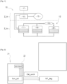
- FIG. 4 shows time graphs representing signals observable during the implementation of the cooling circuit operation diagnostic method 10.
- Graph G1 highlights an activation of diagnostic monitoring Surv_act at time t0 from the moment when all conditions C1-C6 prerequisites for activating the diagnostic were checked during the duration tempo_1.
- Graph G2 illustrates the evolution of the coolant temperature Temp_liq_TBT in the very low temperature circuit 10 compared to the barycentric temperature threshold S_temp.
- Graph G3 highlights the area between times t1 and t3, during which the coolant temperature Tem_liq_TBT exceeds the barycentric temperature threshold S_temp (the coolant temperature of the very low temperature circuit 10 remains high, although the high voltage battery 15 has become colder).
- the Tempo_2 timer starts to determine whether this situation is one-off or whether this situation will persist over time.
- Graph G4 shows that at the end of the Tempo_2 time delay of around 120s occurring at time t3, an overheating detection fault Det_surch is reported.
- the Tempo_2 time delay confirms that the coolant overheating problem is not a one-off and that a fault needs to be dealt with.
- Graph G5 illustrates the sending of a diagnostic signal to the GD-GAR modules which activates the degraded operating mode MF_Deg consisting of requesting a control of the pump 13 at its maximum flow rate, a stop of the electric machine 17, and a restart of the thermal engine.
- This degraded operating mode MF_Deg is thus triggered if the diagnostic monitoring is activated and if the fault is detected.
- the degraded operating mode MF_Deg is triggered when the temperature of the coolant Temp_liq_TBT exceeds a first temperature threshold and is cancelled when the temperature of the coolant Temp_liq_TBT falls below a second temperature threshold lower than the first threshold.
- the preconditions C1-C6 are not taken into account. The degraded operating mode MF_Deg is then triggered as soon as the coolant temperature Temp_liq_TBT exceeds the temperature threshold S_Temp.
Landscapes
- Engineering & Computer Science (AREA)
- Power Engineering (AREA)
- Mechanical Engineering (AREA)
- Transportation (AREA)
- Life Sciences & Earth Sciences (AREA)
- Sustainable Energy (AREA)
- Sustainable Development (AREA)
- Chemical & Material Sciences (AREA)
- General Chemical & Material Sciences (AREA)
- Electrochemistry (AREA)
- Chemical Kinetics & Catalysis (AREA)
- Manufacturing & Machinery (AREA)
- Automation & Control Theory (AREA)
- Electric Propulsion And Braking For Vehicles (AREA)
- Air-Conditioning For Vehicles (AREA)
Description
- La présente invention porte sur un procédé de diagnostic d'efficacité d'un circuit de refroidissement d'une batterie. L'invention trouve une application particulièrement avantageuse avec les dispositifs de contrôle-commande de véhicules hybrides ou électriques.
- De tels véhicules comportent une ou plusieurs machines électriques tournantes utilisées pour assurer la propulsion du véhicule fonctionnant en mode électrique. Ces machines électriques sont alimentées par au moins une batterie haute tension via au moins un onduleur. Ces composants électriques étant fortement sollicités, la température augmente par effet joule, ce qui nécessite la mise en place d'un circuit de refroidissement adapté.
- Le circuit de refroidissement, dit très basse température, comporte un échangeur thermique couplé à un circuit de climatisation ainsi qu'une pompe pilotée pour faire circuler le liquide caloporteur, tel que de l'eau contenant de l'antigel, à l'intérieur de la batterie d'alimentation.
- On connait par exemple des documents de brevet
DE-A1-102017217685 un procédé de diagnostic de fonctionnement d'un circuit de refroidissement d'au moins une batterie d'une machine électrique tournante- pour un véhicule automobile. - On connait en outre du document de brevet
DE-B3-102013008743 un procédé conforme au préambule de la revendication 1. - En effet, l'état thermique de ces composants a un rôle direct sur les performances et la disponibilité du système de propulsion, de récupération électrique, et de charge électrique du véhicule. Il existe donc le besoin de résoudre des problématiques liées à la surchauffe des composants du circuit très basse température rendant impossible l'utilisation de la machine électrique en mode hybride ou électrique.
- L'invention vise à combler efficacement ce besoin en proposant un procédé de diagnostic de fonctionnement d'un circuit de refroidissement d'au moins une batterie d'une machine électrique tournante pour un véhicule automobile, ledit circuit de refroidissement comportant notamment un échangeur thermique et une pompe pour faire circuler un liquide de refroidissement dans ledit circuit de refroidissement, ledit procédé comportant :
- une étape de mesure d'une température du liquide de refroidissement dans le circuit de refroidissement,
- une étape de détermination d'un seuil de température,
- une étape de surveillance par comparaison de la température du liquide de refroidissement avec le seuil de température,- et dans le cas où la température du liquide de refroidissement dépasse le seuil de température, ledit procédé comporte une étape d'enclenchement d'un mode de fonctionnement dégradé, le seuil de température étant estimé à partir d'un barycentre entre une température d'air extérieure et une température de composants de la batterie, et l'étape de surveillance étant enclenchée uniquement si les conditions suivantes préalables à sa réalisation sont vérifiées :
- aucune remontée de défaut de la pompe,
- aucune remontée de défaut électrique sur un capteur de liquide de refroidissement associé à la batterie,
- aucune remontée de défaut de présence de liquide de refroidissement par la batterie,
- un compresseur de climatisation est activé,
- une électrovanne de l'échangeur thermique est activée sans remontée de défaut électrique,
- une température d'air extérieur est stable depuis une durée prédéterminée.
- L'invention permet ainsi d'assurer une surveillance du besoin de refroidissement de la batterie de puissance, afin d'éviter une situation de vie dans laquelle l'utilisation du mode de fonctionnement électrique du véhicule automobile n'est plus possible. L'invention permet ainsi d'augmenter la durabilité des composants en évitant des surchauffes répétées importantes de la batterie.
- Selon une mise en oeuvre, le mode de fonctionnement dégradé est enclenché si la température du liquide de refroidissement reste supérieure au seuil de température au moins pendant une durée prédéterminée. Cette durée permet de confirmer que la surchauffe n'est pas ponctuelle et s'inscrit bien dans la durée.
- Selon une mise en oeuvre, le mode de fonctionnement dégradé consiste à réaliser au moins une opération, de préférence toutes les opérations, parmi:
- un redémarrage d'un moteur thermique dans le cas où le véhicule automobile est du type hybride,
- un arrêt de la machine électrique tournante,
- une demande de pilotage de la pompe à son débit maximum.
- Selon une mise en oeuvre, l'étape de surveillance est activée dans le cas où les conditions préalables sont vérifiées au moins pendant une durée prédéterminée.
- Selon une mise en oeuvre, ledit procédé comporte en outre une étape de remontée d'un défaut vers un calculateur apte à piloter un enclenchement du mode de fonctionnement dégradé.
- L'invention a également pour objet un calculateur comportant une mémoire stockant des fonctions logicielles pour la mise en oeuvre du procédé de diagnostic de fonctionnement d'un circuit de refroidissement tel que précédemment défini.
- L'invention concerne en outre un véhicule automobile comportant un calculateur tel que précédemment défini.
- L'invention sera mieux comprise à la lecture de la description qui suit et à l'examen des figures qui l'accompagnent. Ces figures ne sont données qu'à titre illustratif mais nullement limitatif de l'invention.
- [
Fig. 1 ] Lafigure 1 est une représentation schématique d'un circuit de refroidissement basse température avec lequel est mis en oeuvre le procédé de diagnostic selon la présente invention; - [
Fig. 2 ] Lafigure 2 est une représentation schématique d'une architecture fonctionnelle selon l'invention du diagnostic de fonctionnement du circuit très basse température; - [
Fig. 3 ] Lafigure 3 est une représentation schématique fonctionnelle des différentes étapes du procédé selon l'invention de diagnostic de fonctionnement du circuit très basse température; - [
Fig. 4 ] Lafigure 4 montre des graphiques temporels représentant des signaux observables lors de la mise en oeuvre du procédé de diagnostic de fonctionnement du circuit de refroidissement. - Les éléments identiques, similaires, ou analogues conservent la même référence d'une figure à l'autre.
- La
figure 1 montre un circuit de refroidissement 10, dit très basse température, comportant un échangeur thermique 11 couplé à un circuit de climatisation 12 ainsi qu'une pompe pilotée 13 pour faire circuler le liquide caloporteur, tel que de l'eau contenant de l'anti-gel, dans le circuit de refroidissement, notamment à l'intérieur d'une batterie 15 d'alimentation d'une machine électrique tournante 17. La batterie 15 pourra notamment présenter une tension de fonctionnement de 24 Volts ou de 48 Volts, voire une tension supérieure. La batterie 15 et la pompe 13 sont disposées dans la zone arrière Z_Ar du véhicule, tandis que le circuit de climatisation 12 ainsi que l'échangeur thermique 11 sont disposés dans la zone avant Z_Av du véhicule automobile. L'échangeur thermique assure un échange thermique entre le liquide de refroidissement du circuit de refroidissement 10 et le fluide caloporteur du circuit de climatisation 12. - Le circuit de climatisation 12 comporte un évaporateur 18 au sein duquel un fluide réfrigérant absorbe la chaleur de l'air de l'habitacle en changeant d'état physique, c'est-à-dire en passant totalement en phase gazeuse. En sortie de l'évaporateur 18, le gaz frigorigène circule dans les canalisations jusqu'à un compresseur 19 dans lequel il est comprimé. Le gaz frigorigène haute pression en sortie du compresseur 19 est introduit dans un condenseur 20 au sein duquel le gaz frigorigène cède sa chaleur à l'air extérieur traversant le condenseur 20 grâce à l'avancement du véhicule et/ou au fonctionnement d'un groupe moto-ventilateur. Ce faisant, le fluide frigorigène change à nouveau d'état physique et repasse totalement en phase liquide.
- On décrit ci-après, en référence avec les
figures 2 et3 , un procédé de diagnostic de fonctionnement du circuit de refroidissement 10 de la batterie 15. - A cet effet, un calculateur 21 qui pourra être le calculateur moteur ou un calculateur dédié, notamment un calculateur dit "OBD" (pour "On-Board Diagnostic") est destiné à retourner des diagnostics de fonctionnement de composants du moteur et de ses circuits annexes. Le calculateur 21 comporte une mémoire 22 stockant des fonctions logicielles pour la mise en oeuvre du procédé selon l'invention.
- En cas de remontée d'un défaut lié à une surchauffe de la batterie 15, un module de gestion de diagnostic (GD) confirme le diagnostic, tandis qu'un module de gestion d'actions de reconfiguration (GAR) est apte à piloter, suite à une détection Det_surch d'une surchauffe du liquide de refroidissement du circuit 10, l'enclenchement d'un mode de fonctionnement dégradé MF_Deg décrit plus en détails ci-après.
- Plus précisément, comme on peut le voir sur la
figure 3 , le calculateur 21 s'assure préalablement à l'activation de la surveillance de la température du liquide de refroidissement que les conditions C1-C6 sont vérifiées via une porte logique PL de type "ET". - La condition C1 correspond au fait qu'aucun défaut de la pompe pilotée 13 n'est remonté.
- La condition C2 correspond au fait qu'aucun défaut électrique sur un capteur de température du liquide de refroidissement associé à la batterie 15 n'est remonté.
- La condition C3 correspond au fait qu'aucun défaut de présence de liquide de refroidissement n'est remonté par la batterie 15.
- La condition C4 correspond au fait que le compresseur 19 de climatisation est activé, notamment avec un régime positif.
- La condition C5 correspond au fait que l'électrovanne de l'échangeur thermique 11 est activée sans remontée de défaut électrique.
- La condition C6 correspond au fait que la température d'air extérieur est stable depuis une durée prédéterminée.
- Ces conditions préalables C1-C6 permettent de garantir une détection de diagnostic robuste. La surveillance Surv_act du diagnostic d'efficacité du système de refroidissement est activée dans le cas où les conditions préalables sont vérifiées au moins pendant une durée prédéterminée Tempo_1. La durée Tempo_1 est par exemple comprise entre 1 seconde et 2 secondes.
- Le calculateur 21 mesure une température du liquide de refroidissement Temp_liq_TBT dans le circuit de refroidissement 10, notamment à proximité de la batterie 15.
- Le calculateur 21 détermine également un seuil de température S_temp. Ce seuil de température est composé d'un barycentre entre une température d'air extérieure Temp_ext et une température de composants Temp_comp de la batterie 15 permettant d'évaluer une température d'ambiance au niveau de l'environnement de la batterie 15. En variante, le seuil de température S_temp pourrait être un seuil fixe prédéterminé.
- Le calculateur 21 assure alors une surveillance par comparaison, via un comparateur Comp, de la température du liquide de refroidissement Temp_liq_TBT avec le seuil de température S_temp. Dans le cas où la température du liquide de refroidissement Temp_liq_TBT dépasse le seuil de température S_temp, le calculateur 21 enclenche le mode de fonctionnement dégradé MF_Deg.
- Le mode de fonctionnement dégradé MF_Deg consiste à réaliser au moins une opération, de préférence toutes les opérations, parmi:
- un redémarrage du moteur thermique dans le cas où le véhicule est du type hybride,
- un arrêt de la machine électrique tournante 17 afin de protéger la batterie 15 en évitant sa détérioration dans le cas d'un fonctionnement en surchauffe,
- une demande de pilotage de la pompe 13 à son débit maximum afin d'évacuer au maximum la chaleur générée par la batterie 15 et optimiser ainsi son refroidissement.
- Le mode de fonctionnement dégradé MF_Deg est enclenché de préférence uniquement si la température du liquide de refroidissement reste supérieure à ce seuil estimé au moins pendant une durée prédéterminée Tempo_2, notamment comprise entre 30s et 200s, et de préférence de l'ordre de 120s. Cette durée Tempo_2 permet de confirmer que la surchauffe n'est pas ponctuelle et s'inscrit bien dans la durée. En outre, le calculateur 21 doit pouvoir vérifier que les conditions d'activation C1_C6 de la surveillance du diagnostic ont bien été observées pendant la durée Tempo_1 pour en déduire qu'il existe réellement un défaut au niveau du circuit de refroidissement 10. Ainsi, pour que le mode de fonctionnement dégradé MF_Deg soit enclenché, il faut que la surveillance Surv_act soit activée suite à la vérification des conditions C1-C6 au moins pendant la durée Tempo_1 et qu'une surchauffe Det_surch soit détectée au moins pendant la durée Tempo_2.
- La
figure 4 montre des graphiques temporels représentant des signaux observables lors de la mise en oeuvre du procédé de diagnostic de fonctionnement du circuit de refroidissement 10. - Le graphique G1 met en évidence une activation de la surveillance du diagnostic Surv_act à l'instant t0 à partir du moment où toutes les conditions C1-C6 préalables à l'activation du diagnostic ont été vérifiées pendant la durée tempo_1.
- Le graphique G2 illustre l'évolution de la température du liquide de refroidissement Temp_liq_TBT dans le circuit très basse température 10 par rapport au seuil de température barycentrique S_temp.
- Le graphique G3 met en évidence la zone située entre les instants t1 et t3, pendant laquelle la température du liquide de refroidissement Tem_liq_TBT dépasse le seuil de température barycentrique S_temp (la température du liquide de refroidissement du circuit très basse température 10 reste élevée, bien que la batterie 15 haute tension soit devenue plus froide).
- A partir du moment où le dépassement du seuil S_temp est constaté à l'instant t1, la temporisation Tempo_2 s'enclenche pour déterminer si cette situation est ponctuelle ou si cette situation s'installe dans la durée.
- Le graphique G4 montre qu'à la fin de la durée de temporisation Tempo_2 de l'ordre de 120s se produisant à l'instant t3, un défaut de détection de surchauffe Det_surch est remonté. La temporisation Tempo_2 permet de confirmer que le problème de surchauffe du liquide de refroidissement n'est pas ponctuel et qu'un défaut est à traiter.
- Le graphique G5 illustre l'envoi d'un signal de diagnostic aux modules GD-GAR qui active le mode de fonctionnement dégradé MF_Deg consistant à demander un pilotage de la pompe 13 à son débit maximum, un arrêt de la machine électrique 17, et un redémarrage du moteur thermique. Ce mode de fonctionnement dégradé MF_Deg est ainsi déclenché si la surveillance du diagnostic est activée et si le défaut est détecté.
- Le diagnostic retombe et le mode de fonctionnement dégradé MF_Deg est arrêté à partir de l'instant t3 où le défaut n'est plus constaté, c'est-à-dire lorsque la température du liquide de refroidissement du circuit 10 repasse en-dessous du seuil de température barycentrique à l'instant t3.
- En variante, il aurait pu être possible d'embarquer un fonctionnement d'hystérésis sur la température du liquide de refroidissement du circuit 10 suivant lequel le mode de fonctionnement dégradé MF_Deg est enclenché lorsque la température du liquide de refroidissement Temp_liq_TBT dépasse un premier seuil de température et est annulé lorsque la température du liquide de refroidissement Temp_liq_TBT repasse sous un deuxième seuil de température inférieur au premier seuil.
En variante, dans une mise en oeuvre dégradée du procédé, on ne tient pas compte des conditions préalables C1-C6. Le mode de fonctionnement dégradé MF_Deg est alors enclenché dès que la température du liquide de refroidissement Temp_liq_TBT dépasse le seuil de température S_Temp.
Claims (7)
- Procédé de diagnostic de fonctionnement d'un circuit de refroidissement (10) d'au moins une batterie (15) d'une machine électrique tournante (17) pour un véhicule automobile, ledit circuit de refroidissement (10) comportant notamment un échangeur thermique (11) et une pompe (13) pour faire circuler un liquide de refroidissement dans ledit circuit de refroidissement, ledit procédé comportant:- une étape de mesure d'une température du liquide de refroidissement (Temp_liq_TBT) dans le circuit de refroidissement (10),- une étape de détermination d'un seuil de température (S_Temp),- une étape de surveillance (Surv_act) par comparaison de la température du liquide de refroidissement (Temp_liq_TBT) avec le seuil de température (S_temp),- et dans le cas où la température du liquide de refroidissement (Temp_liq_TBT) dépasse le seuil de température (S_temp), ledit procédé comporte une étape d'enclenchement d'un mode de fonctionnement dégradé (MF_Deg),caractérisé en ce que le seuil de température (S_temp) est estimé à partir d'un barycentre entre une température d'air extérieure (Temp_ext) et une température de composants (Temp_comp) de la batterie (15), et en ce que l'étape de surveillance (Surv_act) est enclenchée uniquement si les conditions suivantes préalables à sa réalisation sont vérifiées:- aucune remontée de défaut de la pompe (13),- aucune remontée de défaut électrique sur un capteur de liquide de refroidissement associé à la batterie (15),- aucune remontée de défaut de présence de liquide de refroidissement par la batterie (15),- un compresseur de climatisation (19) est activé,- une électrovanne de l'échangeur thermique (11) est activée sans remontée de défaut électrique,- une température d'air extérieur est stable depuis une durée prédéterminée.
- Procédé selon la revendication 1, caractérisé en ce que le mode de fonctionnement dégradé (MF_Deg) est enclenché si la température du liquide de refroidissement (Temp_liq_TBT) reste supérieure au seuil de température (S_temp) au moins pendant une durée prédéterminée (Tempo_2).
- Procédé selon la revendication 1 ou 2, caractérisé en ce que le mode de fonctionnement dégradé (MF_Deg) consiste à réaliser au moins une opération, de préférence toutes les opérations, parmi:- un redémarrage d'un moteur thermique dans le cas où le véhicule automobile est du type hybride,- un arrêt de la machine électrique tournante (17),- une demande de pilotage de la pompe (13) à son débit maximum.
- Procédé selon l'une quelconque des revendications 1 à 3, caractérisé en ce que l'étape de surveillance (Surv_act) est activée dans le cas où les conditions préalables sont vérifiées au moins pendant une durée prédéterminée (Tempo_1).
- Procédé selon l'une quelconque des revendications 1 à 4, caractérisé en ce qu'il comporte en outre une étape de remontée d'un défaut vers un calculateur (21) apte à piloter un enclenchement du mode de fonctionnement dégradé (MF_Deg).
- Calculateur (21) comportant une mémoire (22) stockant des fonctions logicielles pour la mise en oeuvre du procédé de diagnostic de fonctionnement d'un circuit de refroidissement (10) tel que défini selon l'une quelconque des revendications précédentes.
- Véhicule automobile caractérisé en ce qu'il comporte un calculateur (21) tel que défini selon la revendication 6
Applications Claiming Priority (2)
| Application Number | Priority Date | Filing Date | Title |
|---|---|---|---|
| FR1900515A FR3091839B1 (fr) | 2019-01-22 | 2019-01-22 | Procede de diagnostic d'efficacite d'un circuit de refroidissement d'une batterie |
| PCT/FR2019/052979 WO2020152404A1 (fr) | 2019-01-22 | 2019-12-09 | Procede de diagnostic d'efficacite d'un circuit de refroidissement d'une batterie |
Publications (2)
| Publication Number | Publication Date |
|---|---|
| EP3914472A1 EP3914472A1 (fr) | 2021-12-01 |
| EP3914472B1 true EP3914472B1 (fr) | 2024-08-14 |
Family
ID=67262453
Family Applications (1)
| Application Number | Title | Priority Date | Filing Date |
|---|---|---|---|
| EP19842794.0A Active EP3914472B1 (fr) | 2019-01-22 | 2019-12-09 | Procede de diagnostic d'efficacite d'un circuit de refroidissement d'une batterie |
Country Status (4)
| Country | Link |
|---|---|
| EP (1) | EP3914472B1 (fr) |
| CN (1) | CN113329905B (fr) |
| FR (1) | FR3091839B1 (fr) |
| WO (1) | WO2020152404A1 (fr) |
Families Citing this family (8)
| Publication number | Priority date | Publication date | Assignee | Title |
|---|---|---|---|---|
| FR3091839B1 (fr) * | 2019-01-22 | 2021-12-17 | Psa Automobiles Sa | Procede de diagnostic d'efficacite d'un circuit de refroidissement d'une batterie |
| CN113829960B (zh) * | 2021-09-07 | 2023-10-20 | 岚图汽车科技有限公司 | 一种电动汽车控制方法、装置、介质及电子设备 |
| CN114185374B (zh) * | 2021-11-26 | 2023-09-08 | 深圳市英维克信息技术有限公司 | 目标进液温度控制方法、系统、温度控制方法及相关设备 |
| CN114335817B (zh) * | 2021-12-30 | 2023-07-28 | 重庆金康动力新能源有限公司 | 一种电池包温度管理方法及相关设备 |
| CN114725569A (zh) * | 2022-05-07 | 2022-07-08 | 阳光储能技术有限公司 | 一种冷却控制系统及方法 |
| JP7694605B2 (ja) * | 2023-05-22 | 2025-06-18 | トヨタ自動車株式会社 | 加熱システムの制御装置、それを備える車両、および、熱媒体の管理方法 |
| CN116901709B (zh) * | 2023-08-23 | 2026-03-13 | 中国第一汽车股份有限公司 | 电池冷却能力的诊断方法、装置、存储介质及电子设备 |
| CN117656942B (zh) * | 2023-12-07 | 2024-08-06 | 汇工(河北)机械集团有限公司 | 电动矿卡的充电冷却控制方法、热管理系统及电动矿卡 |
Citations (2)
| Publication number | Priority date | Publication date | Assignee | Title |
|---|---|---|---|---|
| US5834132A (en) * | 1994-11-14 | 1998-11-10 | Honda Giken Kogyo Kabushiki Kaisha | Battery temperature regulating apparatus |
| FR3091839A1 (fr) * | 2019-01-22 | 2020-07-24 | Psa Automobiles Sa | Procede de diagnostic d'efficacite d'un circuit de refroidissement d'une batterie |
Family Cites Families (18)
| Publication number | Priority date | Publication date | Assignee | Title |
|---|---|---|---|---|
| DE3810174C2 (de) * | 1988-03-25 | 1996-09-19 | Hella Kg Hueck & Co | Einrichtung zur Regelung der Kühlmitteltemperatur einer Brennkraftmaschine, insbesondere in Kraftfahrzeugen |
| JP4977956B2 (ja) * | 2005-02-18 | 2012-07-18 | 日産自動車株式会社 | 燃料電池システムの冷却制御装置 |
| DE102007004979A1 (de) * | 2007-02-01 | 2008-08-07 | Daimler Ag | Vorrichtung zur Kühlung einer Hybridfahrzeugbatterie |
| JP2010104129A (ja) * | 2008-10-22 | 2010-05-06 | Sanyo Electric Co Ltd | 電源システム、電源側制御部及び電動車輌 |
| CN102315498B (zh) * | 2010-06-30 | 2014-08-20 | 上海汽车集团股份有限公司 | 电池热管理控制方法 |
| US9096134B2 (en) * | 2012-01-24 | 2015-08-04 | GM Global Technology Operations LLC | Enhanced HV pre-charge heater diagnostic detection system for liquid cooled HV battery packs |
| JP2013165041A (ja) * | 2012-02-13 | 2013-08-22 | Toyota Industries Corp | 電池温度制御装置 |
| FR3005374B1 (fr) * | 2013-05-02 | 2016-05-27 | Renault Sa | Procede de gestion du refroidissement d'une batterie a seuils de refroidissement ajustables |
| DE102013008743B3 (de) * | 2013-05-23 | 2014-10-16 | Audi Ag | Verfahren zur Steuerung eines Kühlmittelflusses in einem Kraftfahrzeug und Kraftfahrzeug |
| CN104716396A (zh) * | 2013-12-11 | 2015-06-17 | 观致汽车有限公司 | 一种车用动力电池组的冷却系统 |
| US20150291054A1 (en) * | 2014-04-15 | 2015-10-15 | Ford Global Technologies, Llc | Traction Battery Air Thermal Management Control System |
| KR101592720B1 (ko) * | 2014-07-02 | 2016-02-19 | 현대자동차주식회사 | 연료전지 시스템의 운전 제어 방법 |
| US20160031340A1 (en) * | 2014-07-30 | 2016-02-04 | Ford Global Technologies, Llc | Method to determine the running state of a coolant pump in a battery thermal management system for an electrified vehicle |
| FR3043604B1 (fr) * | 2015-11-13 | 2019-05-03 | Renault S.A.S | Systeme et procede de surveillance du couple moteur d'un vehicule electrique ou hybride |
| DE102017217685B4 (de) * | 2017-07-12 | 2021-10-14 | Ford Global Technologies, Llc | Anordnung zur Temperierung einer Batterie und weiterer elektrischer Komponenten eines Fahrzeugs, Fahrzeug sowie Verfahren zur Steuerung der Anordnung |
| CN107394308B (zh) * | 2017-07-17 | 2020-02-07 | 广州汽车集团股份有限公司 | 车辆电池充电冷却的系统及方法 |
| CN108482056A (zh) * | 2018-02-02 | 2018-09-04 | 东华大学 | 一种远程启动充电中电动汽车空调的节能装置及方法 |
| CN108631023A (zh) * | 2018-04-28 | 2018-10-09 | 吉林大学 | 一种精细化液流形式电池冷却方法 |
-
2019
- 2019-01-22 FR FR1900515A patent/FR3091839B1/fr not_active Expired - Fee Related
- 2019-12-09 EP EP19842794.0A patent/EP3914472B1/fr active Active
- 2019-12-09 WO PCT/FR2019/052979 patent/WO2020152404A1/fr not_active Ceased
- 2019-12-09 CN CN201980089915.5A patent/CN113329905B/zh active Active
Patent Citations (2)
| Publication number | Priority date | Publication date | Assignee | Title |
|---|---|---|---|---|
| US5834132A (en) * | 1994-11-14 | 1998-11-10 | Honda Giken Kogyo Kabushiki Kaisha | Battery temperature regulating apparatus |
| FR3091839A1 (fr) * | 2019-01-22 | 2020-07-24 | Psa Automobiles Sa | Procede de diagnostic d'efficacite d'un circuit de refroidissement d'une batterie |
Also Published As
| Publication number | Publication date |
|---|---|
| WO2020152404A1 (fr) | 2020-07-30 |
| EP3914472A1 (fr) | 2021-12-01 |
| CN113329905B (zh) | 2024-05-24 |
| FR3091839B1 (fr) | 2021-12-17 |
| FR3091839A1 (fr) | 2020-07-24 |
| CN113329905A (zh) | 2021-08-31 |
Similar Documents
| Publication | Publication Date | Title |
|---|---|---|
| EP3914472B1 (fr) | Procede de diagnostic d'efficacite d'un circuit de refroidissement d'une batterie | |
| US9631585B2 (en) | EGHR mechanism diagnostics | |
| EP2822788B1 (fr) | Procede de commande automatique destine au degivrage d'une pompe a chaleur pour vehicule | |
| EP3870818B1 (fr) | Procédé de refroidissement d'un équipement d'un véhicule et véhicule comprenant cet équipement | |
| EP3559426B1 (fr) | Procédé de pilotage d'un système de refroidissement pour un véhicule hybride comportant un circuit de transfert de liquide de refroidissement | |
| WO2011124847A1 (fr) | Dispositif de refroidissement pour vehicule automobile | |
| EP4088126B1 (fr) | Diagnostic d'état d'une batterie de servitude d'un véhicule par impulsions de courant | |
| CN114865126A (zh) | 一种动力电池冷却方法、装置、车辆和存储介质 | |
| FR3027259A1 (fr) | Procede de pilotage et de regulation thermique d'un systeme de prolongation d'autonomie d'un vehicule automobile | |
| FR3097172A1 (fr) | Procede de gestion thermique d’une batterie permettant d’adapter le seuil de declenchement de la regulation thermique en fonction de la puissance electrique transferee | |
| EP4500129B1 (fr) | Surveillance du bon fonctionnement d'un capteur de température du circuit caloporteur de la batterie de traction | |
| JP2007032534A (ja) | 熱発電装置 | |
| EP3947933B1 (fr) | Procede de diagnostic d'un systeme de refroidissement d'un circuit electrique de propulsion | |
| EP3747080B1 (fr) | Procédé de refroidissement d'un dispositif de stockage électrique équipant un véhicule | |
| EP4338252A1 (fr) | Procédé de protection thermique d'un dispositif de charge embarqué de vehicule électrifié | |
| WO2010116107A1 (fr) | Dispositif de refroidissement pour véhicule automobile | |
| FR3102718A1 (fr) | Procédé de refroidissement d’éléments d’un véhicule équipé d’un moteur électrique | |
| WO2020212127A1 (fr) | Procede de controle d'un dispositif de gestion thermique d'un vehicule automobile | |
| FR2820369A1 (fr) | Vehicule automobile equipe d'un systeme de climatisation et procede de commande d'un tel systeme | |
| FR3163902A1 (fr) | Procede de commande pour la regulation thermique d’un vehicule hybride | |
| FR3109432A1 (fr) | Traitement thermique apres mise a l’arret d’un vehicule automobile a traction electrique | |
| EP4601895A1 (fr) | Systeme de gestion thermique pour vehicule hybride ou electrique | |
| FR3163970A1 (fr) | Procede de detection d’une anomalie de pompe a eau et de reconfiguration d’un groupe electromoteur | |
| WO2014067836A1 (fr) | Gestion du refroidissement d'un systeme de moteur equipe d'un dispositif de recirculation partielle des gaz d'echappement | |
| CN116466681A (zh) | 一种混动车故障诊断方法、装置、存储介质及控制器 |
Legal Events
| Date | Code | Title | Description |
|---|---|---|---|
| STAA | Information on the status of an ep patent application or granted ep patent |
Free format text: STATUS: UNKNOWN |
|
| STAA | Information on the status of an ep patent application or granted ep patent |
Free format text: STATUS: THE INTERNATIONAL PUBLICATION HAS BEEN MADE |
|
| PUAI | Public reference made under article 153(3) epc to a published international application that has entered the european phase |
Free format text: ORIGINAL CODE: 0009012 |
|
| STAA | Information on the status of an ep patent application or granted ep patent |
Free format text: STATUS: REQUEST FOR EXAMINATION WAS MADE |
|
| 17P | Request for examination filed |
Effective date: 20210614 |
|
| AK | Designated contracting states |
Kind code of ref document: A1 Designated state(s): AL AT BE BG CH CY CZ DE DK EE ES FI FR GB GR HR HU IE IS IT LI LT LU LV MC MK MT NL NO PL PT RO RS SE SI SK SM TR |
|
| DAV | Request for validation of the european patent (deleted) | ||
| DAX | Request for extension of the european patent (deleted) | ||
| STAA | Information on the status of an ep patent application or granted ep patent |
Free format text: STATUS: EXAMINATION IS IN PROGRESS |
|
| RIC1 | Information provided on ipc code assigned before grant |
Ipc: B60K 1/00 20060101ALI20230217BHEP Ipc: B60L 1/00 20060101ALI20230217BHEP Ipc: B60H 1/00 20060101ALI20230217BHEP Ipc: B60L 1/02 20060101ALI20230217BHEP Ipc: B60L 3/00 20060101ALI20230217BHEP Ipc: B60L 3/12 20060101ALI20230217BHEP Ipc: B60L 50/60 20190101ALI20230217BHEP Ipc: B60L 50/61 20190101ALI20230217BHEP Ipc: H01M 10/613 20140101ALI20230217BHEP Ipc: H01M 10/625 20140101ALI20230217BHEP Ipc: H01M 10/66 20140101ALI20230217BHEP Ipc: B60K 11/02 20060101ALI20230217BHEP Ipc: H01M 10/63 20140101ALI20230217BHEP Ipc: H01M 10/6567 20140101ALI20230217BHEP Ipc: H01M 10/663 20140101ALI20230217BHEP Ipc: B60L 58/26 20190101AFI20230217BHEP |
|
| 17Q | First examination report despatched |
Effective date: 20230313 |
|
| RAP3 | Party data changed (applicant data changed or rights of an application transferred) |
Owner name: STELLANTIS AUTO SAS |
|
| GRAP | Despatch of communication of intention to grant a patent |
Free format text: ORIGINAL CODE: EPIDOSNIGR1 |
|
| STAA | Information on the status of an ep patent application or granted ep patent |
Free format text: STATUS: GRANT OF PATENT IS INTENDED |
|
| INTG | Intention to grant announced |
Effective date: 20240418 |
|
| GRAS | Grant fee paid |
Free format text: ORIGINAL CODE: EPIDOSNIGR3 |
|
| GRAA | (expected) grant |
Free format text: ORIGINAL CODE: 0009210 |
|
| STAA | Information on the status of an ep patent application or granted ep patent |
Free format text: STATUS: THE PATENT HAS BEEN GRANTED |
|
| AK | Designated contracting states |
Kind code of ref document: B1 Designated state(s): AL AT BE BG CH CY CZ DE DK EE ES FI FR GB GR HR HU IE IS IT LI LT LU LV MC MK MT NL NO PL PT RO RS SE SI SK SM TR |
|
| REG | Reference to a national code |
Ref country code: GB Ref legal event code: FG4D Free format text: NOT ENGLISH |
|
| REG | Reference to a national code |
Ref country code: CH Ref legal event code: EP |
|
| REG | Reference to a national code |
Ref country code: DE Ref legal event code: R096 Ref document number: 602019057124 Country of ref document: DE |
|
| REG | Reference to a national code |
Ref country code: IE Ref legal event code: FG4D Free format text: LANGUAGE OF EP DOCUMENT: FRENCH |
|
| REG | Reference to a national code |
Ref country code: DE Ref legal event code: R084 Ref document number: 602019057124 Country of ref document: DE |
|
| REG | Reference to a national code |
Ref country code: LT Ref legal event code: MG9D |
|
| REG | Reference to a national code |
Ref country code: NL Ref legal event code: MP Effective date: 20240814 |
|
| PG25 | Lapsed in a contracting state [announced via postgrant information from national office to epo] |
Ref country code: NO Free format text: LAPSE BECAUSE OF FAILURE TO SUBMIT A TRANSLATION OF THE DESCRIPTION OR TO PAY THE FEE WITHIN THE PRESCRIBED TIME-LIMIT Effective date: 20241114 |
|
| REG | Reference to a national code |
Ref country code: AT Ref legal event code: MK05 Ref document number: 1713000 Country of ref document: AT Kind code of ref document: T Effective date: 20240814 |
|
| PG25 | Lapsed in a contracting state [announced via postgrant information from national office to epo] |
Ref country code: FI Free format text: LAPSE BECAUSE OF FAILURE TO SUBMIT A TRANSLATION OF THE DESCRIPTION OR TO PAY THE FEE WITHIN THE PRESCRIBED TIME-LIMIT Effective date: 20240814 Ref country code: NL Free format text: LAPSE BECAUSE OF FAILURE TO SUBMIT A TRANSLATION OF THE DESCRIPTION OR TO PAY THE FEE WITHIN THE PRESCRIBED TIME-LIMIT Effective date: 20240814 Ref country code: PT Free format text: LAPSE BECAUSE OF FAILURE TO SUBMIT A TRANSLATION OF THE DESCRIPTION OR TO PAY THE FEE WITHIN THE PRESCRIBED TIME-LIMIT Effective date: 20241216 Ref country code: GR Free format text: LAPSE BECAUSE OF FAILURE TO SUBMIT A TRANSLATION OF THE DESCRIPTION OR TO PAY THE FEE WITHIN THE PRESCRIBED TIME-LIMIT Effective date: 20241115 Ref country code: PL Free format text: LAPSE BECAUSE OF FAILURE TO SUBMIT A TRANSLATION OF THE DESCRIPTION OR TO PAY THE FEE WITHIN THE PRESCRIBED TIME-LIMIT Effective date: 20240814 |
|
| PG25 | Lapsed in a contracting state [announced via postgrant information from national office to epo] |
Ref country code: BG Free format text: LAPSE BECAUSE OF FAILURE TO SUBMIT A TRANSLATION OF THE DESCRIPTION OR TO PAY THE FEE WITHIN THE PRESCRIBED TIME-LIMIT Effective date: 20240814 |
|
| PG25 | Lapsed in a contracting state [announced via postgrant information from national office to epo] |
Ref country code: LV Free format text: LAPSE BECAUSE OF FAILURE TO SUBMIT A TRANSLATION OF THE DESCRIPTION OR TO PAY THE FEE WITHIN THE PRESCRIBED TIME-LIMIT Effective date: 20240814 |
|
| PG25 | Lapsed in a contracting state [announced via postgrant information from national office to epo] |
Ref country code: IS Free format text: LAPSE BECAUSE OF FAILURE TO SUBMIT A TRANSLATION OF THE DESCRIPTION OR TO PAY THE FEE WITHIN THE PRESCRIBED TIME-LIMIT Effective date: 20241214 Ref country code: AT Free format text: LAPSE BECAUSE OF FAILURE TO SUBMIT A TRANSLATION OF THE DESCRIPTION OR TO PAY THE FEE WITHIN THE PRESCRIBED TIME-LIMIT Effective date: 20240814 |
|
| PG25 | Lapsed in a contracting state [announced via postgrant information from national office to epo] |
Ref country code: HR Free format text: LAPSE BECAUSE OF FAILURE TO SUBMIT A TRANSLATION OF THE DESCRIPTION OR TO PAY THE FEE WITHIN THE PRESCRIBED TIME-LIMIT Effective date: 20240814 |
|
| PG25 | Lapsed in a contracting state [announced via postgrant information from national office to epo] |
Ref country code: ES Free format text: LAPSE BECAUSE OF FAILURE TO SUBMIT A TRANSLATION OF THE DESCRIPTION OR TO PAY THE FEE WITHIN THE PRESCRIBED TIME-LIMIT Effective date: 20240814 Ref country code: RS Free format text: LAPSE BECAUSE OF FAILURE TO SUBMIT A TRANSLATION OF THE DESCRIPTION OR TO PAY THE FEE WITHIN THE PRESCRIBED TIME-LIMIT Effective date: 20241114 |
|
| PG25 | Lapsed in a contracting state [announced via postgrant information from national office to epo] |
Ref country code: RS Free format text: LAPSE BECAUSE OF FAILURE TO SUBMIT A TRANSLATION OF THE DESCRIPTION OR TO PAY THE FEE WITHIN THE PRESCRIBED TIME-LIMIT Effective date: 20241114 Ref country code: PT Free format text: LAPSE BECAUSE OF FAILURE TO SUBMIT A TRANSLATION OF THE DESCRIPTION OR TO PAY THE FEE WITHIN THE PRESCRIBED TIME-LIMIT Effective date: 20241216 Ref country code: PL Free format text: LAPSE BECAUSE OF FAILURE TO SUBMIT A TRANSLATION OF THE DESCRIPTION OR TO PAY THE FEE WITHIN THE PRESCRIBED TIME-LIMIT Effective date: 20240814 Ref country code: NO Free format text: LAPSE BECAUSE OF FAILURE TO SUBMIT A TRANSLATION OF THE DESCRIPTION OR TO PAY THE FEE WITHIN THE PRESCRIBED TIME-LIMIT Effective date: 20241114 Ref country code: NL Free format text: LAPSE BECAUSE OF FAILURE TO SUBMIT A TRANSLATION OF THE DESCRIPTION OR TO PAY THE FEE WITHIN THE PRESCRIBED TIME-LIMIT Effective date: 20240814 Ref country code: LV Free format text: LAPSE BECAUSE OF FAILURE TO SUBMIT A TRANSLATION OF THE DESCRIPTION OR TO PAY THE FEE WITHIN THE PRESCRIBED TIME-LIMIT Effective date: 20240814 Ref country code: IS Free format text: LAPSE BECAUSE OF FAILURE TO SUBMIT A TRANSLATION OF THE DESCRIPTION OR TO PAY THE FEE WITHIN THE PRESCRIBED TIME-LIMIT Effective date: 20241214 Ref country code: HR Free format text: LAPSE BECAUSE OF FAILURE TO SUBMIT A TRANSLATION OF THE DESCRIPTION OR TO PAY THE FEE WITHIN THE PRESCRIBED TIME-LIMIT Effective date: 20240814 Ref country code: GR Free format text: LAPSE BECAUSE OF FAILURE TO SUBMIT A TRANSLATION OF THE DESCRIPTION OR TO PAY THE FEE WITHIN THE PRESCRIBED TIME-LIMIT Effective date: 20241115 Ref country code: FI Free format text: LAPSE BECAUSE OF FAILURE TO SUBMIT A TRANSLATION OF THE DESCRIPTION OR TO PAY THE FEE WITHIN THE PRESCRIBED TIME-LIMIT Effective date: 20240814 Ref country code: ES Free format text: LAPSE BECAUSE OF FAILURE TO SUBMIT A TRANSLATION OF THE DESCRIPTION OR TO PAY THE FEE WITHIN THE PRESCRIBED TIME-LIMIT Effective date: 20240814 Ref country code: BG Free format text: LAPSE BECAUSE OF FAILURE TO SUBMIT A TRANSLATION OF THE DESCRIPTION OR TO PAY THE FEE WITHIN THE PRESCRIBED TIME-LIMIT Effective date: 20240814 Ref country code: AT Free format text: LAPSE BECAUSE OF FAILURE TO SUBMIT A TRANSLATION OF THE DESCRIPTION OR TO PAY THE FEE WITHIN THE PRESCRIBED TIME-LIMIT Effective date: 20240814 |
|
| PG25 | Lapsed in a contracting state [announced via postgrant information from national office to epo] |
Ref country code: DK Free format text: LAPSE BECAUSE OF FAILURE TO SUBMIT A TRANSLATION OF THE DESCRIPTION OR TO PAY THE FEE WITHIN THE PRESCRIBED TIME-LIMIT Effective date: 20240814 Ref country code: SM Free format text: LAPSE BECAUSE OF FAILURE TO SUBMIT A TRANSLATION OF THE DESCRIPTION OR TO PAY THE FEE WITHIN THE PRESCRIBED TIME-LIMIT Effective date: 20240814 Ref country code: RO Free format text: LAPSE BECAUSE OF FAILURE TO SUBMIT A TRANSLATION OF THE DESCRIPTION OR TO PAY THE FEE WITHIN THE PRESCRIBED TIME-LIMIT Effective date: 20240814 |
|
| PG25 | Lapsed in a contracting state [announced via postgrant information from national office to epo] |
Ref country code: EE Free format text: LAPSE BECAUSE OF FAILURE TO SUBMIT A TRANSLATION OF THE DESCRIPTION OR TO PAY THE FEE WITHIN THE PRESCRIBED TIME-LIMIT Effective date: 20240814 |
|
| PG25 | Lapsed in a contracting state [announced via postgrant information from national office to epo] |
Ref country code: CZ Free format text: LAPSE BECAUSE OF FAILURE TO SUBMIT A TRANSLATION OF THE DESCRIPTION OR TO PAY THE FEE WITHIN THE PRESCRIBED TIME-LIMIT Effective date: 20240814 |
|
| PG25 | Lapsed in a contracting state [announced via postgrant information from national office to epo] |
Ref country code: IT Free format text: LAPSE BECAUSE OF FAILURE TO SUBMIT A TRANSLATION OF THE DESCRIPTION OR TO PAY THE FEE WITHIN THE PRESCRIBED TIME-LIMIT Effective date: 20240814 Ref country code: SK Free format text: LAPSE BECAUSE OF FAILURE TO SUBMIT A TRANSLATION OF THE DESCRIPTION OR TO PAY THE FEE WITHIN THE PRESCRIBED TIME-LIMIT Effective date: 20240814 |
|
| REG | Reference to a national code |
Ref country code: DE Ref legal event code: R097 Ref document number: 602019057124 Country of ref document: DE |
|
| PLBE | No opposition filed within time limit |
Free format text: ORIGINAL CODE: 0009261 |
|
| STAA | Information on the status of an ep patent application or granted ep patent |
Free format text: STATUS: NO OPPOSITION FILED WITHIN TIME LIMIT |
|
| PG25 | Lapsed in a contracting state [announced via postgrant information from national office to epo] |
Ref country code: MC Free format text: LAPSE BECAUSE OF FAILURE TO SUBMIT A TRANSLATION OF THE DESCRIPTION OR TO PAY THE FEE WITHIN THE PRESCRIBED TIME-LIMIT Effective date: 20240814 |
|
| 26N | No opposition filed |
Effective date: 20250515 |
|
| REG | Reference to a national code |
Ref country code: CH Ref legal event code: PL |
|
| PG25 | Lapsed in a contracting state [announced via postgrant information from national office to epo] |
Ref country code: LU Free format text: LAPSE BECAUSE OF NON-PAYMENT OF DUE FEES Effective date: 20241209 |
|
| GBPC | Gb: european patent ceased through non-payment of renewal fee |
Effective date: 20241209 |
|
| PG25 | Lapsed in a contracting state [announced via postgrant information from national office to epo] |
Ref country code: SE Free format text: LAPSE BECAUSE OF FAILURE TO SUBMIT A TRANSLATION OF THE DESCRIPTION OR TO PAY THE FEE WITHIN THE PRESCRIBED TIME-LIMIT Effective date: 20240814 |
|
| REG | Reference to a national code |
Ref country code: BE Ref legal event code: MM Effective date: 20241231 |
|
| PG25 | Lapsed in a contracting state [announced via postgrant information from national office to epo] |
Ref country code: BE Free format text: LAPSE BECAUSE OF NON-PAYMENT OF DUE FEES Effective date: 20241231 Ref country code: GB Free format text: LAPSE BECAUSE OF NON-PAYMENT OF DUE FEES Effective date: 20241209 |
|
| PG25 | Lapsed in a contracting state [announced via postgrant information from national office to epo] |
Ref country code: CH Free format text: LAPSE BECAUSE OF NON-PAYMENT OF DUE FEES Effective date: 20241231 |
|
| PG25 | Lapsed in a contracting state [announced via postgrant information from national office to epo] |
Ref country code: IE Free format text: LAPSE BECAUSE OF NON-PAYMENT OF DUE FEES Effective date: 20241209 |
|
| PGFP | Annual fee paid to national office [announced via postgrant information from national office to epo] |
Ref country code: DE Payment date: 20251126 Year of fee payment: 7 |
|
| PGFP | Annual fee paid to national office [announced via postgrant information from national office to epo] |
Ref country code: FR Payment date: 20251120 Year of fee payment: 7 |